Article

Trajectory Tracking Control of a Skid-Steer Mobile Robot Based on Nonlinear Model Predictive Control with a Hydraulic Motor Velocity Mapping

1
School of Mechanical and Electrical Engineering, Central South University, Changsha 410083, China
2
State Key Laboratory of Precision Manufacturing for Extreme Service Performance, Changsha 410083, China
3
College of Mechanical and Electrical Engineering, Hunan Agricultural University, Changsha 410128, China
4
Sunward Intelligent Equipment Co., Ltd., Changsha 410100, China
*
Author to whom correspondence should be addressed.
Appl. Sci. 2024, 14(1), 122; https://doi.org/10.3390/app14010122
Submission received: 16 November 2023 / Revised: 10 December 2023 / Accepted: 18 December 2023 / Published: 22 December 2023
(This article belongs to the Special Issue Research and Development of Intelligent Robot)

Abstract

:
In this study, we address the trajectory tracking control problem of a hydraulic-driven skid-steer mobile robot. A hierarchical control strategy is proposed to simultaneously consider the robot’s position control and the velocity control of the hydraulic motors. At the upper level, a nonlinear model predictive control (NMPC) method is employed to control the position and heading of the mobile robot. The NMPC controller takes into account the robot’s physical constraints and generates the desired robot motion velocity. Then, to control the hydraulic drive system, a current–velocity mapping-based control method is introduced. By establishing the mapping relationship between the control current applied to the hydraulic motor and its corresponding output velocity, the dynamics of the hydraulic motors are characterized. Consequently, the lower-level controller can directly obtain the control signal for the hydraulic actuator through lookup mappings. Additionally, PID controllers are adopted to compensate for velocity tracking errors. The proposed hierarchical control strategy decouples the robot’s position control and the hydraulic system control, simplifying the overall controller design, leading to improved control performance. To validate the effectiveness of the proposed control strategy, several experiments were conducted on a hydraulic-driven skid-steer mobile robot, and the results demonstrate the effectiveness of the proposed approach.

1. Introduction

With the rapid development of robotics technology, the application of mobile robots has extended from indoor structured environments to unstructured operational settings [1]; typical applications include geological surveying, emergency rescue, military reconnaissance, and so on [2]. The increasing variability of external environments and the growing complexity of tasks pose higher demands on mobile robots [3]. On the one hand, robots operating in complex environments require high reliability and adaptability. Consequently, some robots have foregone traditional steering mechanisms and instead adopted differential steering, which simplifies the robot’s structure while enhancing its adaptability and reliability [4]. On the other hand, the escalating demand for carrying capacity has led to the adoption of hydraulics as the power source. Hydraulic systems offer advantages such as high power-to-weight ratio, low cost, and high reliability [5]. Considering these factors, hydraulic-driven skid-steer mobile robots have garnered significant attention in recent years [5,6,7]. These robots can undertake a variety of tasks in high-risk environments, effectively replacing human involvement. However, trajectory tracking control for mobile robots remains a challenge due to the nonholonomic constraints inherent in their motion and the physical constraints encountered by the actual systems [8]. Furthermore, the nonlinear characteristics of hydraulic-driven systems, parameter variations caused by leaks and friction, and external environmental disturbances make the control of hydraulic-driven mobile robots more intricate compared to motor-driven counterparts, especially when operating on unstructured terrains [9]. Therefore, conducting research on trajectory tracking control for hydraulic-driven skid-steer robots holds paramount importance in the field of robotics.
At present, there has been extensive research on trajectory tracking control methods for skid-steer mobile robots. Various control approaches, including PID control [10], linear quadratic regulator (LQR) [11], sliding mode control [12], robust control [13], and adaptive control [14], have been extensively studied to address the challenges posed by the nonlinearity, nonholonomic constraints, and robustness of mobile robots. However, these control methods have limitations in dealing with various physical constraints, such as actuator power constraints, velocity and acceleration limitations, and so on [15]. Neglecting these physical constraints in control strategies can potentially degrade control performance and even result in system instability [16].
Compared to these methods, Model Predictive Control (MPC) has garnered considerable interest in the field of trajectory tracking control for mobile robots. This is primarily due to its capacity to effectively address physical constraints and generate optimal control inputs [17]. Linearized MPC (LMPC) has been extensively studied in [18], demonstrating its simplicity, efficiency, and ease of solution. Nevertheless, it should be noted that LMPC lacks the capability to directly tackle the point stabilization problem. This limitation arises when the reference velocity of the robot reaches zero, rendering the robot uncontrollable [19]. In contrast, Nonlinear MPC (NMPC) can solve this issue and achieve better tracking accuracy [15]. In one study [20], the control performance of LMPC and NMPC on an articulated skid-steer unmanned vehicle was experimentally compared. Tube-based MPC was employed in [21] to solve the robust tracking control problem of skid-steer loading vehicles. A learning-based NMPC algorithm was proposed in [22] for trajectory tracking control of autonomous mobile robots, aiming to reduce tracking errors when repeatedly traversing along the reference path. Moreover, ref. [23] developed an NMPC based on the P3-AT small mobile robot, addressing the tracking control problem and estimating the robot’s state using the Moving Horizon Estimation (MHE) method.
In the existing literature, most of the MPC-based controllers for mobile robots are designed for electric motor-driven robots. These controllers typically employ kinematic models and adopt the desired velocity as the control output [18,24], which is then sent to the motors for execution. However, for the heavy-duty mobile robots driven by hydraulic systems studied in this research, controlling them is much more complex compared to electric motor-driven systems [25]. This increased difficulty stems from the fundamental nonlinearity of fluid dynamics, compounded by issues such as fluid leakage and friction [26]. When the hydraulic drive system fails to precisely follow the desired velocity, maintaining accurate trajectory tracking for the entire robot becomes a difficult task. Consequently, designing a velocity controller for a hydraulic-driven system is essential, and also a challenging problem. Directly applying nonlinear fluid dynamics for control often fails to meet real-time requirements; thus, some studies have used simplified linear models combined with adaptive mechanisms, such as sliding mode control [27] or backstepping control [9], to handle model uncertainties and improve tracking performance. Meanwhile, obtaining a simplified model of a hydraulic system is a difficult task. The process of parameter identification is often time-consuming and expensive [26]. Additionally, due to cost and installation constraints, there may not be enough sensors available on the actual system to collect the data required for parameter identification [16]. Therefore, there is a need for a control scheme that does not rely on an explicit mechanistic model. Recently, the nonlinear mapping method has been adopted in various fields, including control systems and machine learning. Instead of starting with equations that describe the physics of the hydraulic system, a nonlinear mapping approach would use data collected from the motor’s operation. These data include input variables (current in this study) and output variables (rotational speed in this study). And, by fitting these data into a function, the system can learn the relationship between inputs and outputs.
Motivated by the challenges mentioned above, the trajectory tracking of a hydraulic-driven skid-steer mobile robot requires simultaneous consideration of both the robot’s position control and the velocity control of the hydraulic motors. Due to the complexity of these two control tasks, this research proposes a hierarchical control strategy. The upper-level controller utilizes a nonlinear model predictive control method to track the desired pose while taking into account the physical constraints of the system. And, the lower-level controller is based on the nonlinear velocity mapping of the hydraulic motor. It obtains the reference control value through lookup mappings and employs the PID control method to compensate for errors. The main contributions of this study can be summarized as follows:
(1)
The hierarchical control strategy allows for the decoupling of position control and hydraulic control tasks, thereby simplifying the overall controller design and enhancing the system’s robustness and performance. By separating the control objectives and utilizing different control algorithms at each level, the system effectively addresses the complex dynamics and nonlinearity of the hydraulic-driven skid-steer mobile robot.
(2)
We propose a hydraulic motor control method based on nonlinear current–velocity mapping. By establishing the mapping relationship between the input (control current) and output (motor velocity) of the hydraulic motor, the dynamics are obtained, thus avoiding the need for complex mechanism modeling and parameter identification processes. By adopting this data-driven approach, the requirement for detailed knowledge of system dynamics and precise parameter identification is reduced, making the controller easier to apply in practical robot systems.
(3)
Experimental tests on a heavy-duty hydraulic-driven skid-steer mobile robot were conducted for both velocity tracking control and trajectory tracking control, and the results validate the effectiveness of the proposed control strategy.
The rest of this article is organized as follows. Section 2 introduces the structure of the hydraulic-driven skid-steer mobile robot and the mathematical model of the system. In Section 3, we present the proposed hierarchical control strategy. Section 4 presents the trajectory tracking control results of the mobile robot control experiments. The conclusions of this study are given in Section 5.

2. Problem Description and Modeling

As depicted in Figure 1, the mobile robot studied in this study is a four-wheel hydraulic-driven heavy-duty skid-steer vehicle. The driving system consists of four wheel-side hydraulic motors. Through the mechanical and hydraulic design, the angular velocity of the hydraulic motors on one side is the same. This mechanical connection mode brings great convenience to the control, making the controller similar to the two-wheeled mobile robot [28]. However, due to the large inertia of the heavy-duty robot and the limitations of the actuator power, the controller must consider the physical constraints of the robot. Meanwhile, the nonlinearity of the hydraulic-driven system, the parameter changes caused by leakage and friction, and the interference from the external environment make the control of the hydraulic-driven heavy-duty robot more difficult than that of the electric motor-driven robot, especially when the mobile robot is working on unstructured terrains [2]. Regrettably, the existing research offers few suitable solutions to address this challenge. Meanwhile, this is also the main motivation of this research.

2.1. Mobile Robot Kinematics

Ignoring the slip and deformation of the tires, the kinematic model of the skid-steer mobile robot is represented as follows:
X ˙ = [ x ˙ y ˙ θ ˙ ] = [ v cos θ v sin θ ω ] = [ cos θ 0 sin θ 0 0 1 ] u
where the state vector X = [ x , y , θ ] T is the Cartesian coordinate and the orientation angle, and the control vector u = [ v , ω ] T represents the linear and angle velocity.
According to Equation (1), the reference state vector X r = [ x r , y r , θ r ] T and the reference control vector u r = [ v r , ω r ] T have the following relationship:
X ˙ r = [ x ˙ r y ˙ r θ ˙ r ] = [ v r cos θ r v r sin θ r ω r ] = [ cos θ r 0 sin θ r 0 0 1 ] u r
Then, the kinematic errors can be computed as
X e = [ x e y e θ e ] = [ cos θ sin θ 0 sin θ cos θ 0 0 0 1 ] [ x r x y r y θ r θ ]
According to Equation (3), the error equation can be derived as
x ˙ e = ω y e v + v r cos θ e y e = ω x e + v r sin θ e θ ˙ e = ω r ω
Then, the control input is written as
u e = [ v r cos θ e v ω r ω ]
Substituting (5) to (4), the kinematic model about X e is written as
X ˙ e = [ x ˙ e y ˙ e θ ˙ e ] = [ 0 ω 0 ω 0 v r sin θ e θ e 0 0 0 ] [ x e y e θ e ] + [ 1 0 0 0 0 1 ] u e
In this study, the main purpose of introducing X e is to decouple the control variables u = [ v , ω ] T and state variables X = [ x , y , θ ] T , transforming the non-affine nonlinear model represented by Equation (1) into an affine nonlinear model represented by Equation (6), thereby simplifying the computation of NMPC. Similar approaches can be found in some references, such as [15,19]. By designing an appropriate controller, the state of the system (6) can be controlled to be zero, thereby ensuring that the mobile robot tracks the desired pose.

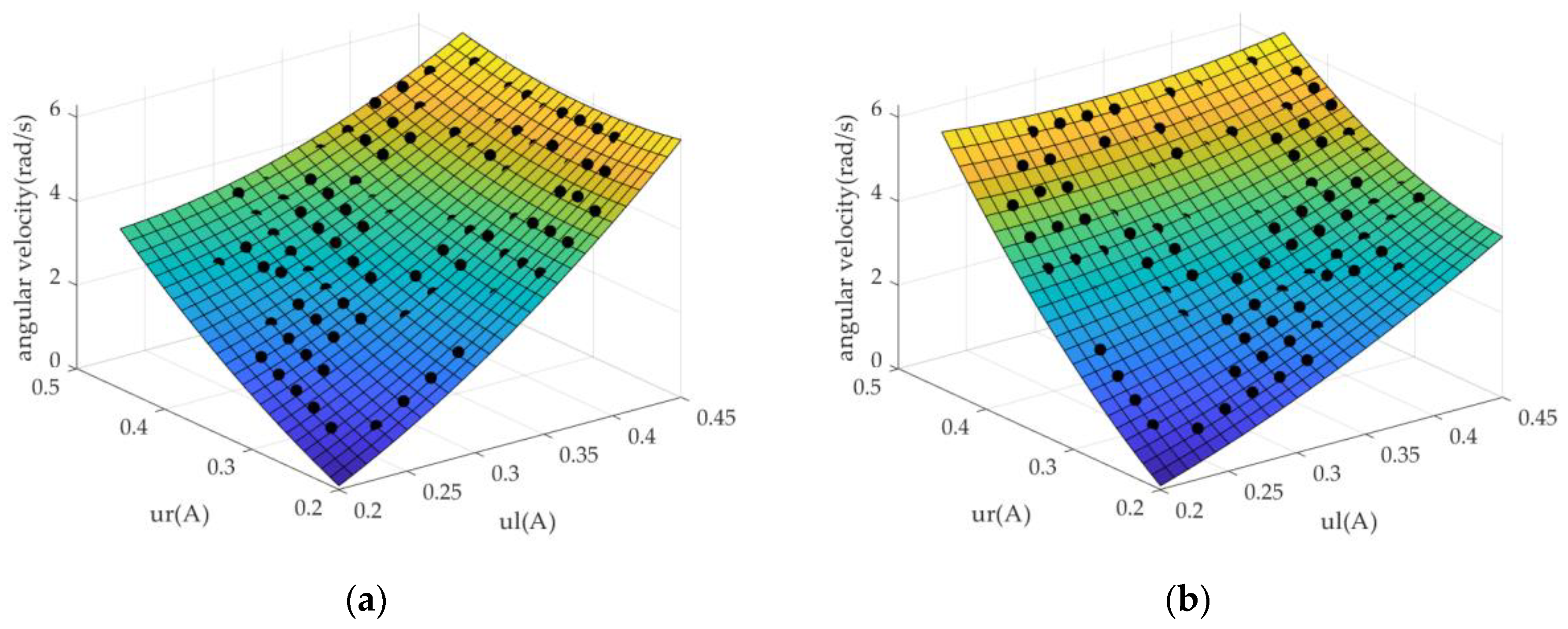
2.2. Nonlinear Velocity Mapping of Hydraulic Motor

As previously mentioned, acquiring the dynamic model of a hydraulic-driven system and accurately identifying its parameters can be a costly and time-consuming process [29]. Consequently, we have proposed hydraulic motor velocity mapping to describe the dynamic characteristics of the hydraulic motors. In order to render the velocity mapping sufficiently accurate and practical, we have assigned distinct control currents to the left and right actuator and tested the angular velocity of the motor under varying control currents. The process of data collection and development of the current–velocity mapping procedure is detailed in Algorithm 1.
According to the dynamics of skid-steer mobile robots, the angular velocity of each motor is not only related the its own control current, but also influenced by the control current of the other side motor, since the mobile robot is driven by actuators on both sides. Therefore, we need to obtain the following relationship as the current–speed mapping of each side hydraulic motor:
M a p p i n g l w m , l = f l ( u l , u r ) M a p p i n g r w m , r = f r ( u l , u r )
where w m , l and w m , r are the angular velocity of the left-side motor and right-side motor, u l and u r are the control current of each side motor, and f l and f r represent nonlinear functions.
The control current [ u l , u r ] and motor angular velocity of the left and right motors [ w m , l , w m , r ] were collected. To accurately fit the mappings, the spline interpolation method was employed; the result is illustrated in Figure 2.
Algorithm 1: Current–Velocity Mapping Building
Input: c m d (control current) [ u l , u r ]
Output: current–velocity mapping of the left and right motor [ M a p l , M a p r ]
Params: current range [ u min , u max ] , sampling step Δ u
1: for u l = u min : Δ u : u max do
2: for u r = u min : Δ u : u max do
3:   c m d = [ u l , u r ]
4:  send c m d to hydraulic system
5:  collect motor velocity [ ω m , l , ω m , r ]
6:  record c m d and [ ω m , l , ω m , r ] when the motor speed is stable
7: end for
8: end for
9: M a p p i n g l     c m d , left motor velocity ω m , l
10: M a p p i n g r     c m d , right motor velocity ω m , r

3. Controller Design

3.1. Overall Framework

In order to address the trajectory tracking control problem of a hydraulic-driven skid-steer mobile robot, a hierarchical control strategy is proposed in this study. This strategy aims to achieve accurate tracking control by considering both the robot’s motion control and the hydraulic drive system control. The overall control structure is depicted in Figure 3 and consists of two main layers: the motion control layer (upper-level controller) and the hydraulic control layer (lower-level controller).
The upper-level controller adopts the NMPC method, which controls the robot to track the desired trajectory, X r = [ x r , y r , θ r ] T . The output [ v d , ω d ] T is the desired linear velocity and angular velocity of the mobile robot. Then, the velocity decoupling module converts [ v d , ω d ] T into the angular velocity of hydraulic motors [ w m , l d , w m , r d ] T , which is the reference input of the lower-level controller. Based on nonlinear current–velocity mapping, a look-up method is adopted in the lower-level controller, which outputs the control current [ u l , u r ] T for hydraulic actuators. In addition, sensors, including RTK-GPS and encoders, are installed to measure the robot posture [ x , y , θ ] T and the angular velocity [ w m , l s , w m , r s ] T , and feedback for the upper-level controller and the lower-level controller, respectively.
The hierarchical control strategy allows for the decoupling of the motion control and hydraulic control tasks, which simplifies the overall controller design and improves the system’s robustness and performance. By separating the control objectives and utilizing different control algorithms at each layer, the system can effectively handle the complex dynamics and nonlinearities of the hydraulic-driven mobile robot.

3.2. The Upper-Level Controller

According to the analysis conducted in Section 2, it was determined that the tracking controller guarantees closed-loop stability as long as there is persistent excitation between the actual positions and the reference positions. In order to address the point stabilization problem while taking into account future movements and various constraints, an NMPC approach has been specifically developed in this section.
Based on the robot kinematic model (6), and using T as the sampling time, we obtain the discretized model as
X e ( k + 1 ) = f ( X e ( k ) ) + g u e ( k )
with
f ( X e ( k ) ) = [ 1 ω T 0 ω T 1 v r sin x 3 x 3 0 0 1 T ]
g = T [ 1 0 0 0 0 1 ]
The principle of the model predictive controller is shown in Figure 4; it employs an explicit model to predict the future outputs of the system and, at each sampling time, solves an optimization problem for the control input. This optimization process will take into consideration the constraints, ensuring that the generated control inputs adhere to the limitations imposed by the system’s dynamics and input boundaries.
The optimal control input is obtained by continuously solving the following optimization problem:
min Δ u e ( k ) J ( k ) = j = 1 N p X e ( k + j | k ) Q 2 + j = 0 N m 1 Δ u e ( k ) W 2
Subject to the constraints
X min X e ( k ) X max u min u e ( k ) u max Δ u min Δ u e ( k ) Δ u max
where N p and N m are the prediction horizon and the control horizon, respectively, and N m N p ; Q and W are weighting matrices for two optimization terms, and 2 denotes the Euclidean norms of vectors; the input increment is Δ u e ( k ) = u e ( k ) u e ( k 1 ) ; and [ u min , u max ] , [ u min , u max ] , and [ u min , u max ] are the boundaries of the control variable, the control increment variable, and the state variable, respectively.
According to the nonlinear affine model (8), we have
{ X e ( k + 1 | k ) = f [ X e ( k | k 1 ) ] + g ( u e ( k 1 ) + Δ u e ( k ) ) X e ( k + 2 | k ) = f [ X e ( k + 1 | k 1 ) ] + g ( u e ( k 1 ) + Δ u e ( k ) + Δ u e ( k + 1 ) ) X e ( k + N p | k ) = f [ X e ( k + N p 1 | k 1 ) ] + g ( u e ( k 1 ) + Δ u e ( k ) + Δ u e ( k + 1 ) + ... + Δ u e ( k + N m 1 ) )
Defining the following vectors:
X ¯ e = [ X e ( k + 1 | k ) ,   X e ( k + 2 | k )   ,   X e ( k + N p | k ) ] N p n x
Δ U = [ Δ u e ( k )   , Δ u e ( k + 1 ) ,     Δ u e ( k + N m 1 ) ] N m n u
Transforming (14) into matrix form, we obtain
X ¯ e = F + V + G Δ U
where
F i = [ f [ X e ( k ) ] f [ X e ( k + 1 | k ) ] f [ X e ( k + p 1 | k ) ] ] N p n x
V = [ g X e ( k 1 ) g X e ( k 1 ) g X e ( k 1 ) ] N p n x
G = [ g 0 0 g g 0 g g g ] N p n x × N m n u
Hence, the original optimization Problem (14) becomes
min Δ U J ( k ) = X ¯ e Q 2 + Δ U W 2 = F + V + G Δ U Q 2 + Δ U W 2 s . t . u m i n u e ( k 1 ) + Δ U u m a x Δ u m i n Δ U Δ u m a x X m i n ( F + V + G Δ U ) X m a x
The optimal control vector can be obtained by solving the above optimization problem, where the first element Δ U ( 1 ) = Δ u e ( k ) will be applied to the robot. Then, we have
u e ( k ) = u e ( k 1 ) + Δ u e ( k )
Based on Equation (5), the desired linear velocity and angular velocity are given as
v d ( k ) = v r ( k ) cos θ e ( k ) u e 1 ( k ) ω d ( k ) = ω r ( k ) u e 2 ( k )
Supposing B is the width of the mobile robot, then the linear velocities of the left and right wheels are v m , l = v d + ω d B 2 and v m , r = v d ω d B 2 , respectively. Accordingly, the desired angular velocity of the left and right wheels is presented as
w m , l = v m , l / R w w m , r = v m , r / R w
where R w is the radius of the wheels.

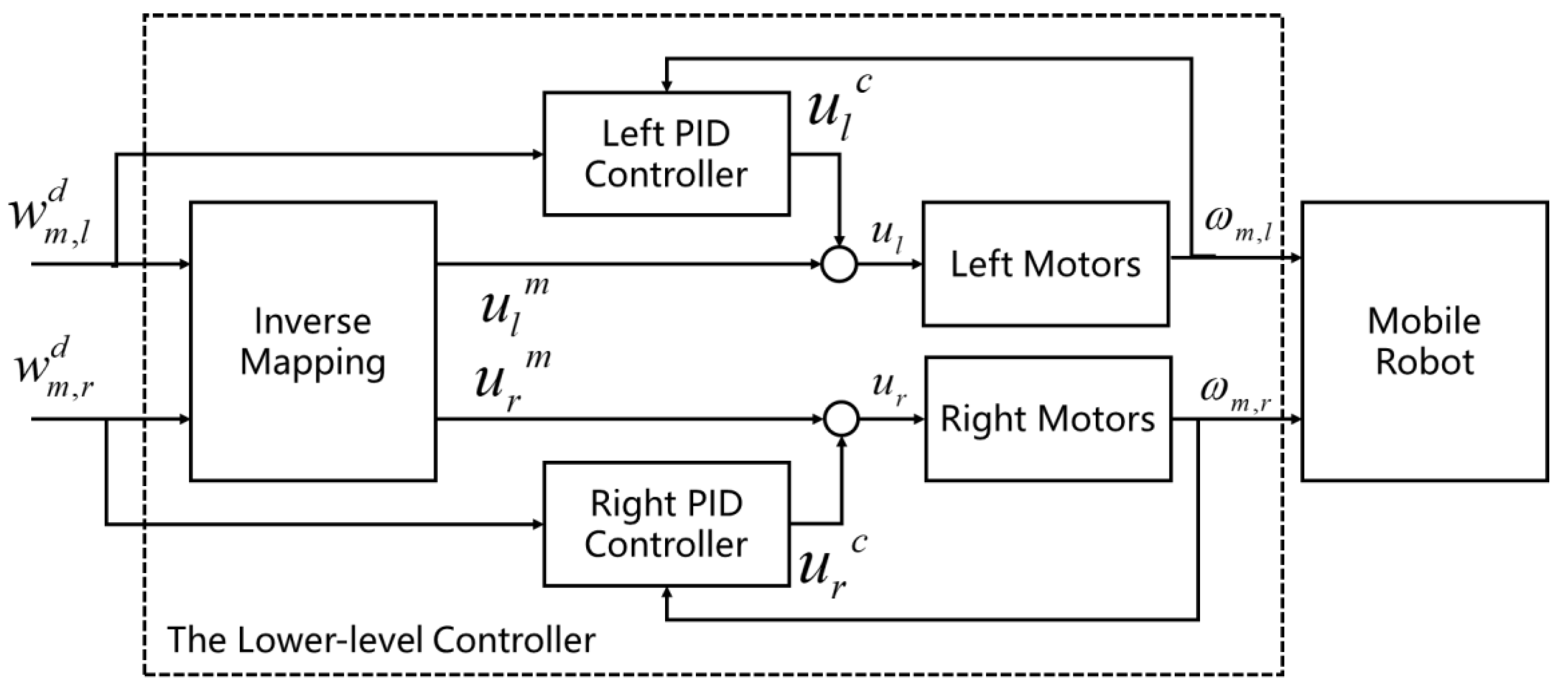
3.3. The Lower-Level Controller

Based on the nonlinear current–velocity mapping of the hydraulic motors, a look-up method is adopted to directly obtain the controller current corresponding to the desired angular velocity of motors. However, the current–velocity mapping can only reflect the static characteristics of the hydraulic system, while in reality, the robot wheel speed is dynamically changing. In addition, the variation of the road conditions and the accuracy of the current–velocity mapping can also lead to the degradation of the control accuracy, so we added PID controllers as compensation for the look-up table method to reduce the velocity tracking error.
According to the hydraulic motors mapping (7), we can define inverse mapping functions, which are given as
M a p p i n g l 1 u l = f l 1 ( w m , l , w m , r ) M a p p i n g r 1 u r = f r 1 ( w m , l , w m , r )
Then, we can obtain the motor current input value according to [ w m , l d , w m , r d ] T ,
u l m = f l 1 ( w m , l d , w m , r d ) u r m = f r 1 ( w m , l d , w m , r d )
where [ u l m , u r m ] are the control values according to inverse mapping functions.
Based on the actual velocity w m , i s and the desired velocity w m , i d , the PID controllers can be obtained with the following equation:
u i c ( t ) = k i , p e i ( t ) + k i , i 0 t e ( t ) d t + k i , d d e i ( t ) d t
where i = l e f t , r i g h t ; u i c is the control values of PID controller; e i = w m , i d w m , i s ; and k i , p , k i , i and k i , d are the controller parameters.
Combining (25) and (26), the controller output values of the lower-level controller are given as (27), and the overall framework of the lower-level controller is shown in Figure 5.
u i = u i m + u i c = f i 1 ( w m , l d , w m , r d ) + k i , p e i ( t ) + k i , i 0 t e ( t ) d t + k i , d d e i ( t ) d t

4. Experiment

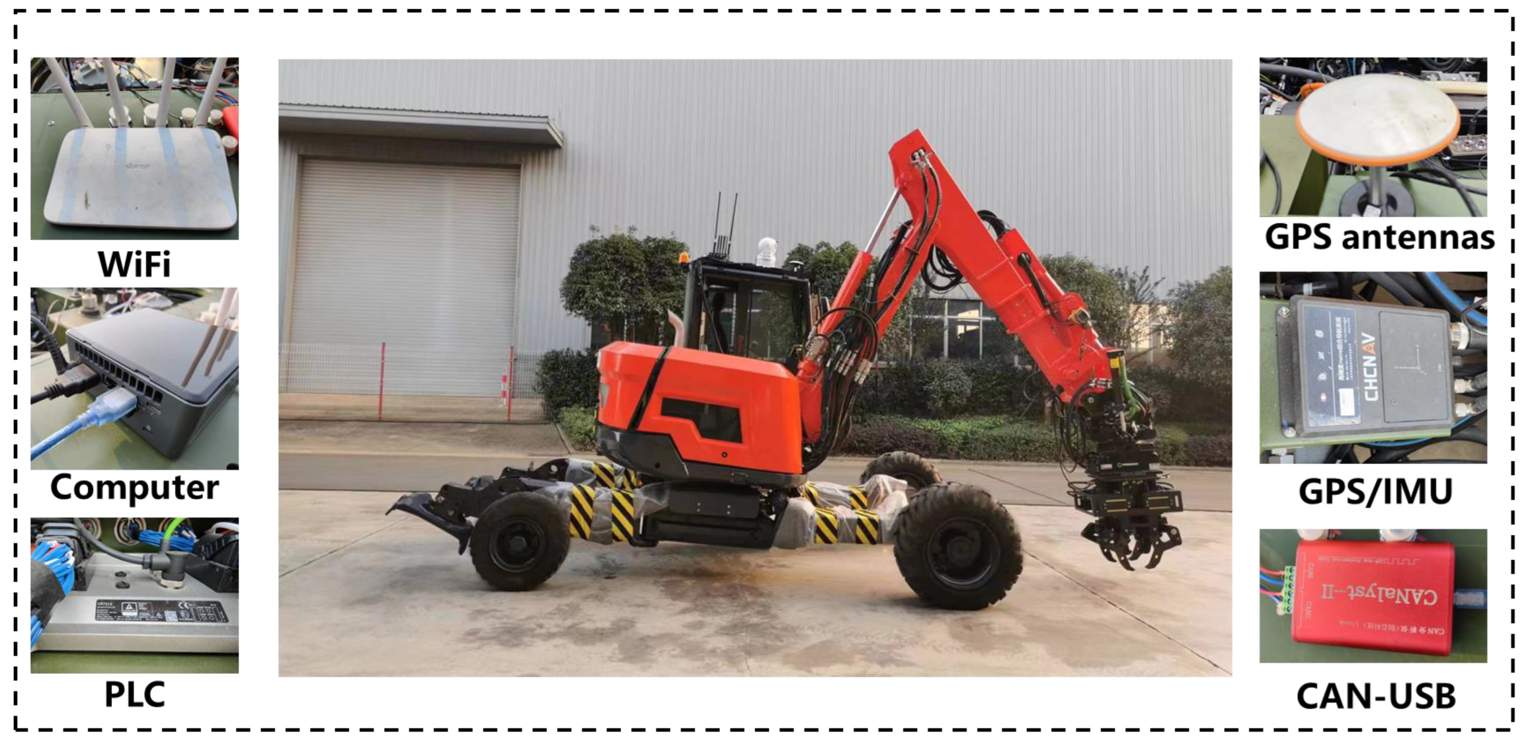
4.1. Experiment Platform

A skid-steer mobile robot was used for the validation of the control strategy. The robot adopted in the experiment is a large heavy-duty hydraulic-driven unmanned ground vehicle, with a width of 3.3 m, length of 6.2 m, and a weight of 6 tons. The configuration of the experimental robot is shown in Figure 6. The robot was equipped with an onboard computer (Intel-NUC) running the Robot Operating System (ROS) to receive the robot’s state and perform tracking control tasks. A combined navigation system, consisting of RTK-GPS and IMU, was used to obtain high-precision positioning and orientation information of the robot, and four wheel-side encoders were used to determine the wheel angular velocity. A Programmable Logic Controller (PLC) was applied for data acquisition and to control current generation, which communicated with the onboard computer through the CAN bus.

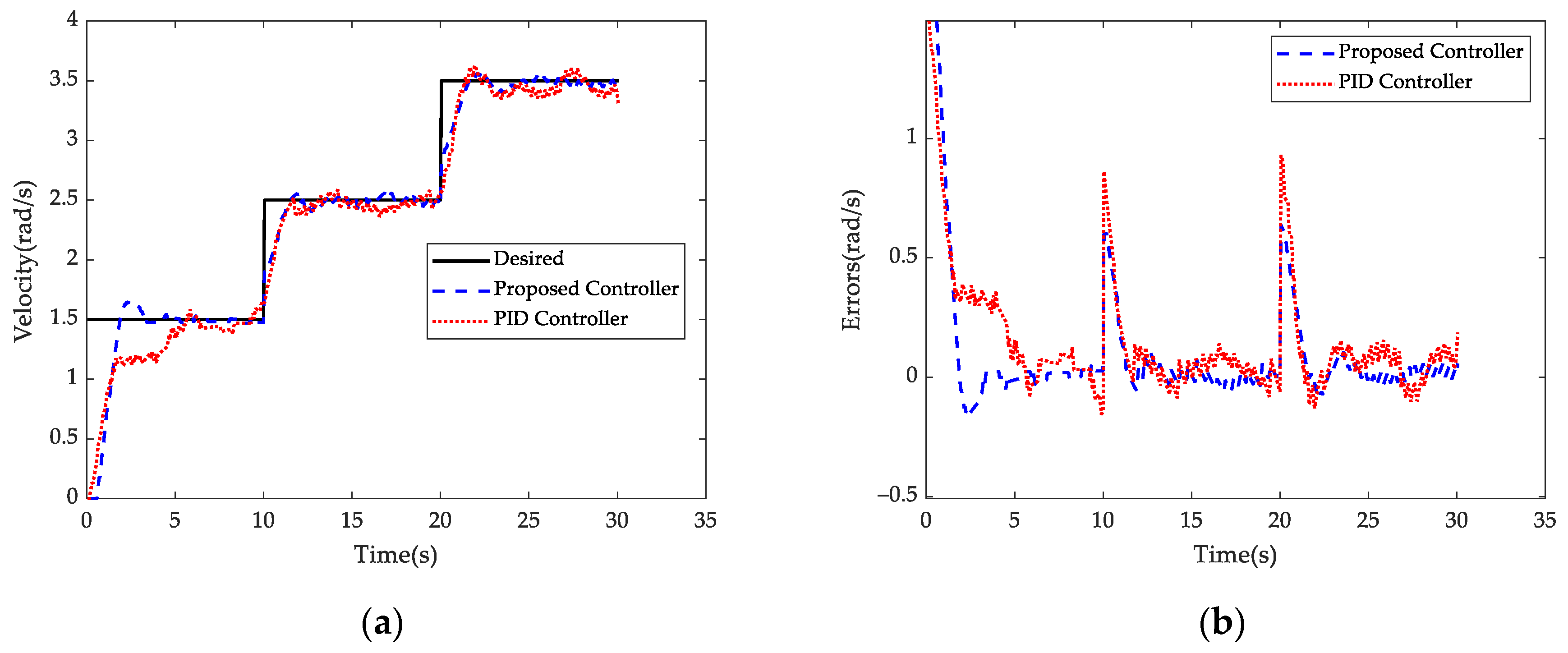
4.2. Verification of the Lower-Level Controller for Velocity Tracking

In this section, velocity tracking experiments were conducted to validate the proposed lower-level controller based on current–velocity mappings. Additionally, we conducted tests using a PID controller for comparative analysis. The target velocity was set to a step velocity represented by Equation (28), with both the left and right motors having the same desired velocity. The sampling time was set to 0.1 s. Detailed parameter settings for the controllers can be found in Table 1.
w i d = { 1.5   rad / s , 0   s < t 10   s 2.5   rad / s , 10   s < t 20   s 3.5   rad / s , 20   s < t 30   s
Figure 7 and Figure 8 present the tracking process for the left and right motors under different controllers, respectively. As depicted in Figure 7a and Figure 8a, it is evident from the results that the lower-level controller proposed in this study exhibits a significantly faster response compared to the traditional PID controllers. When the desired motor velocity changes, the lower-level controller is capable of quickly converging toward the desired velocity while minimizing overshoot. This notable improvement can be attributed to the controller’s ability to directly obtain the reference control values by looking up the nonlinear velocity mappings of the hydraulic motors. Figure 7b and Figure 8b display the tracking errors of the left-side motors and the right-side motors. These results clearly demonstrate the superior performance of the proposed velocity control method over traditional PID controllers.

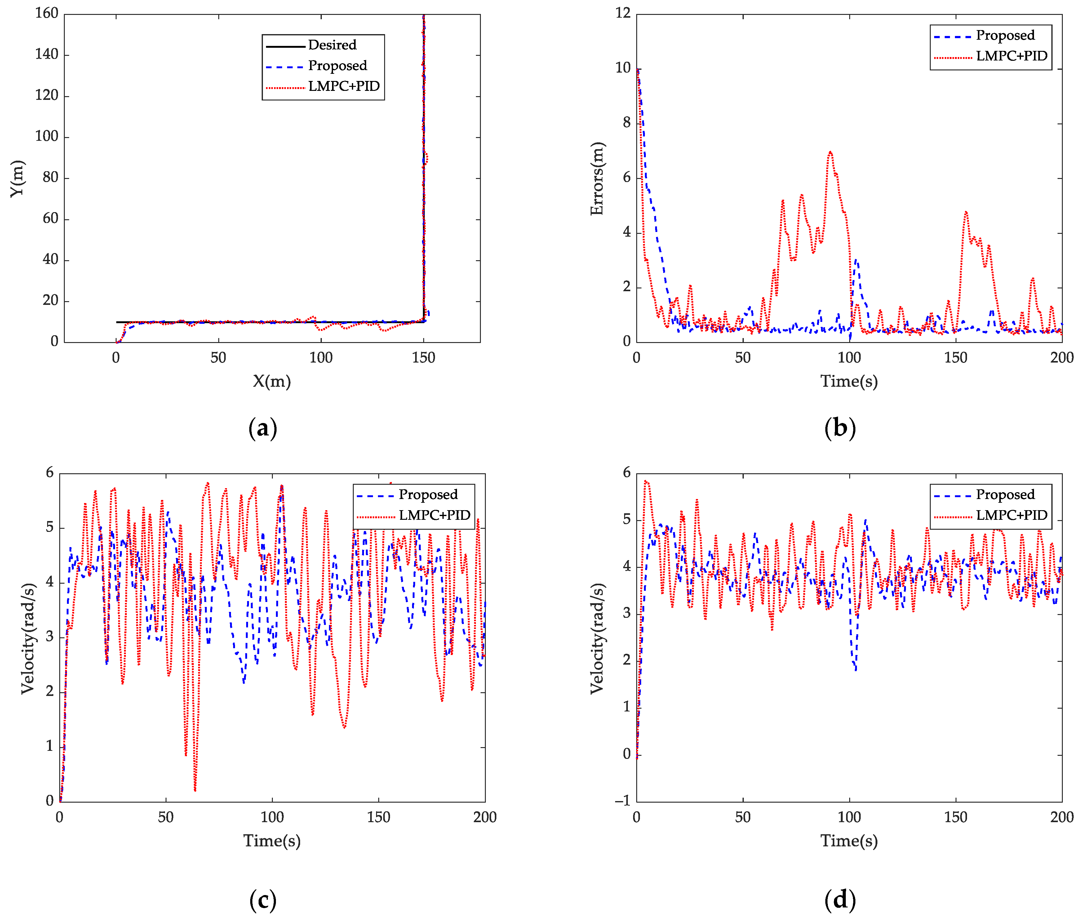
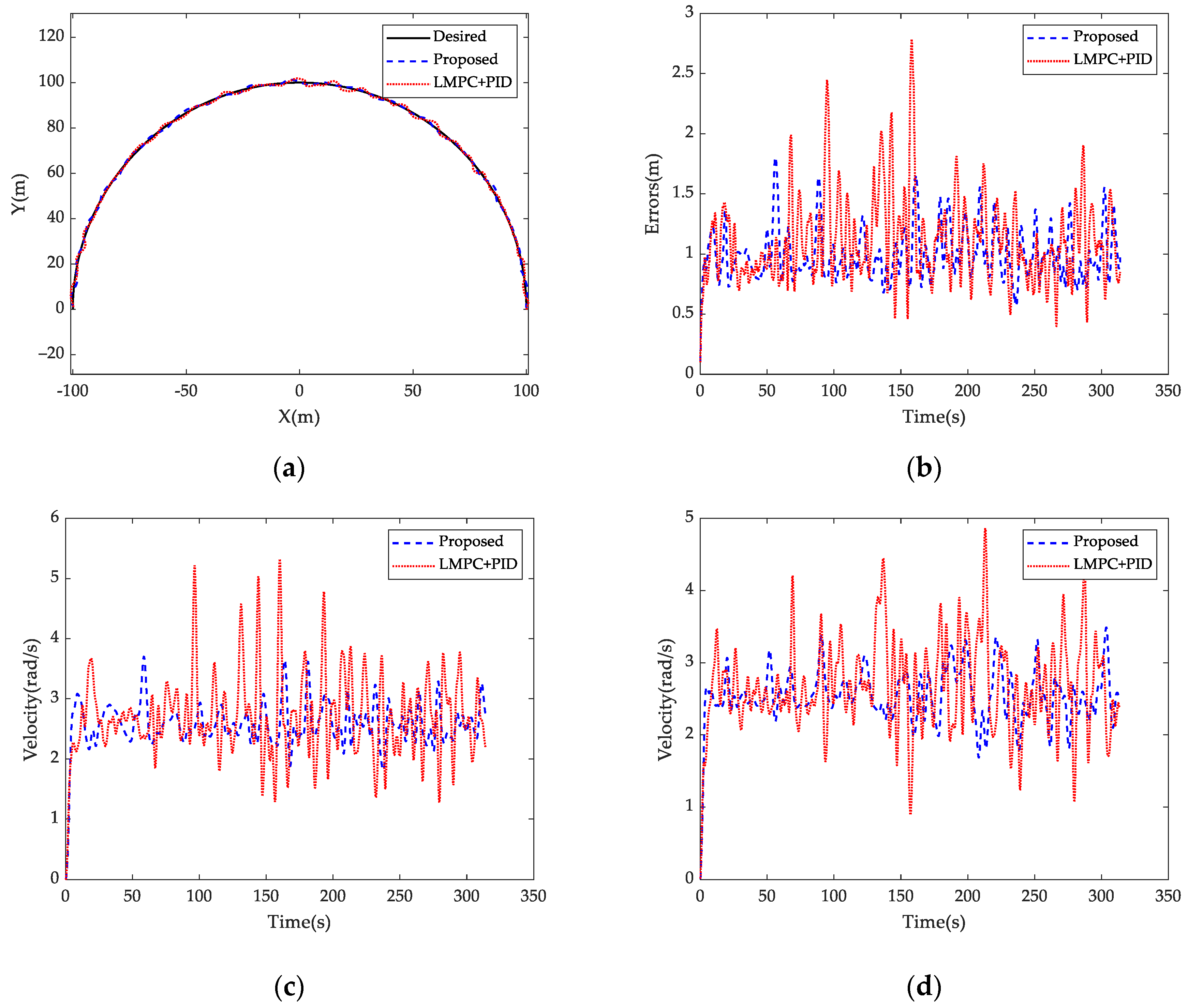
4.3. Verification of the Hierarchical Control Strategy for Trajectory Tracking

To verify the effectiveness of the proposed hierarchical control strategy in this research, we conducted trajectory tracking control experiments, with the contrast controller utilizing LMPC as the upper-level controller and PID as the lower-level controller. The parameters of the controllers are listed in Table 2.
During the experiments, we set different target trajectories, including a simple L-shaped trajectory and a more complex circle-shaped trajectory, in order to evaluate the tracking performance of the proposed control strategy.
Figure 9 depicts the results of the mobile robot tracking the L-shaped trajectory. The initial position and heading angle of the robot are [0, 0, 0]. From Figure 9a, it can be observed that the controller proposed in this study demonstrates better tracking performance compared to the comparative controller (LMPC + PID). The position tracking errors are shown in Figure 9b. Figure 9c,d illustrate the angular velocities of the left and right hydraulic motors during the motion of the robot. It can be observed that when adopting our control method, the velocity fluctuations are smaller, thereby resulting in better motion stability for the mobile robot.
Figure 10 presents the results of the mobile robot tracking the circle-shaped trajectory. The initial position and heading angle of the robot are [100, 0, 1.57]. As expected, we obtained results which are similar to the tracking of the L-shaped trajectory, even with the more complex trajectory. The position tracking errors are shown in Figure 10b. Similarly, Figure 10c,d demonstrate that our controller leads to smaller velocity fluctuations, thereby providing the mobile robot with better motion stability. The experimental results indicate that the hierarchical control strategy proposed in this study exhibits superior trajectory tracking control performance.
The tracking errors of different controllers are shown in Table 3. Due to the initial position of the robot being quite distant from the starting point of the L-shaped trajectory, error calculation was commenced after 20 s. The experimental results show that our proposed hierarchical control scheme exhibits better trajectory tracking control performance, whether it is following an L-shaped trajectory or a circular trajectory.

5. Conclusions

This study presents a novel hierarchical control strategy for trajectory tracking of a hydraulic-driven skid-steer mobile robot. Firstly, a mapping relationship between the control current of the hydraulic motor and its output velocity is established, enabling the acquisition of the motor’s dynamics through data modeling instead of complex mechanism modeling and parameter identification processes. Then, in the upper-level controller, the NMPC is employed to track the desired pose of the mobile robot, while considering the physical constraints of the system. The output of the upper-level controller is the desired velocity. Consequently, in the lower-level controller, the control signal for the hydraulic actuator is obtained directly from looking up the velocity mappings, and a PID controller is utilized to compensate for velocity tracking errors. This hierarchical control strategy effectively decouples the pose control of the robot from the velocity control of the hydraulic system, simplifying the overall controller design. Experimental validation was conducted on a heavy-duty skid-steer mobile robot, and the results demonstrate the superior trajectory tracking control performance achieved by the proposed control strategy.
Our future research will aim to create a more sophisticated, intelligent, and robust control system for skid-steer mobile robots, enabling them to operate efficiently in complex unstructured environments. Firstly, considering the issue of skidding in skid-steer mobile robots, machine learning techniques may be applied to help predict slip before it occurs by analyzing patterns from historical sensor data. Neural networks or support vector machines could be trained to identify the precursors of skidding events. Then, enhancements to the robot’s control algorithms will be crucial. This might involve the development of MPC schemes that can anticipate and adjust for slip, or adaptive control systems that can learn and compensate for the skidding behavior dynamically. Moreover, for SLAM to be effective in unstructured environments, a fusion of different types of sensors (e.g., LIDAR, RADAR, cameras) may be required to provide robust data under varying conditions, such as poor lighting or adverse weather. Meanwhile, developing or improving algorithms that can handle the uncertainty and variability in unstructured environments will be necessary.

Author Contributions

Conceptualization, J.W. and D.Z.; methodology, J.W. and Z.L.; formal analysis, Y.Z. and C.P.; data curation, H.C.; writing—original draft preparation, J.W.; writing—review and editing, D.Z. All authors have read and agreed to the published version of the manuscript.

Funding

This research received no external funding.

Institutional Review Board Statement

Not applicable.

Informed Consent Statement

Not applicable.

Data Availability Statement

The data are not publicly available due to privacy.

Conflicts of Interest

Authors Daqing Zhang and Changfeng Peng were employed by the company Sunward Intelligent Equipment Co., Ltd. The remaining authors declare that the research was conducted in the absence of any commercial or financial relationships that could be construed as a potential conflict of interest.

References

  1. Moysiadis, V.; Tsolakis, N.; Katikaridis, D.; Sørensen, C.G.; Pearson, S.; Bochtis, D. Mobile robotics in agricultural operations: A narrative review on planning aspects. Appl. Sci. 2020, 10, 3453. [Google Scholar] [CrossRef]
  2. Jiang, Y.; Meng, H.; Chen, G.; Yang, C.; Xu, X.; Zhang, L.; Xu, H. Differential-steering based path tracking control and energy-saving torque distribution strategy of 6WID unmanned ground vehicle. Energy 2022, 254, 124209. [Google Scholar] [CrossRef]
  3. Raj, R.; Kos, A. A comprehensive study of mobile robot: History, developments, applications, and future research perspectives. Appl. Sci. 2022, 12, 6951. [Google Scholar] [CrossRef]
  4. Wang, J.; Fader, M.T.H.; Marshall, J.A. Learning-based model predictive control for improved mobile robot path following using Gaussian processes and feedback linearization. J. Field Robot. 2023, 40, 1014–1033. [Google Scholar] [CrossRef]
  5. Zhou, X.; He, J.; He, Q.; Ren, C.; He, M. Motion kinematics analysis of a horse inspired terrain-adaptive unmanned vehicle with four hydraulic swing arms. IEEE Access 2020, 8, 194351–194362. [Google Scholar] [CrossRef]
  6. Wang, Y.; Zhang, Z.; Qin, X.-q. Modeling and control for hydraulic transmission of unmanned ground vehicle. J. Cent. South Univ. 2014, 21, 124–129. [Google Scholar] [CrossRef]
  7. Łopatka, M.J.; Cieślik, K.; Krogul, P.; Muszyński, T.; Przybysz, M.; Rubiec, A.; Spadło, K. Research on Terrain Mobility of UGV with Hydrostatic Wheel Drive and Slip Control Systems. Energies 2023, 16, 6938. [Google Scholar] [CrossRef]
  8. Yu, W.; Chuy, O.Y.; Collins, E.G.; Hollis, P. Analysis and experimental verification for dynamic modeling of a skid-steered wheeled vehicle. IEEE Trans. Robot. 2010, 26, 340–353. [Google Scholar] [CrossRef]
  9. Nakkarat, P.; Kuntanapreeda, S. Observer-based backstepping force control of an electrohydraulic actuator. Control Eng. Pract. 2009, 17, 895–902. [Google Scholar] [CrossRef]
  10. Tiep, D.K.; Lee, K.; Im, D.Y.; Kwak, B.; Ryoo, Y.J. Design of Fuzzy-PID Controller for Path Tracking of Mobile Robot with Differential Drive. Int. J. Fuzzy Log. Intell. Syst. 2018, 18, 220–228. [Google Scholar] [CrossRef]
  11. Xin, G.Y.; Xin, S.Y.; Cebe, O.; Pollayil, M.J.; Angelini, F.; Garabini, M.; Vijayakumar, S.; Mistry, M. Robust Footstep Planning and LQR Control for Dynamic Quadrupedal Locomotion. IEEE Robot. Autom. Lett. 2021, 6, 4488–4495. [Google Scholar] [CrossRef]
  12. Xie, Y.; Zhang, X.; Meng, W.; Zheng, S.; Jiang, L.; Meng, J.; Wang, S. Coupled fractional-order sliding mode control and obstacle avoidance of a four-wheeled steerable mobile robot. ISA Trans. 2021, 108, 282–294. [Google Scholar] [CrossRef] [PubMed]
  13. Ryu, J.C.; Agrawal, S.K. Differential flatness-based robust control of mobile robots in the presence of slip. Int. J. Robot. Res. 2011, 30, 463–475. [Google Scholar] [CrossRef]
  14. Liao, J.; Chen, Z.; Yao, B. Performance-oriented coordinated adaptive robust control for four-wheel independently driven skid steer mobile robot. IEEE Access 2017, 5, 19048–19057. [Google Scholar] [CrossRef]
  15. Zhang, Y.; Zhao, X.; Tao, B.; Ding, H. Point stabilization of nonholonomic mobile robot by Bézier smooth subline constraint nonlinear model predictive control. IEEE-ASME Trans. Mechatron. 2020, 26, 990–1001. [Google Scholar] [CrossRef]
  16. Wang, J.; Zhang, H.; Hao, P.; Deng, H. Observer-Based Approximate Affine Nonlinear Model Predictive Controller for Hydraulic Robotic Excavators with Constraints. Processes 2023, 11, 1918. [Google Scholar] [CrossRef]
  17. Worthmann, K.; Mehrez, M.W.; Zanon, M.; Mann, G.K.I.; Gosine, R.G.; Diehl, M. Model predictive control of nonholonomic mobile robots without stabilizing constraints and costs. IEEE Trans. Control Syst. Technol. 2015, 24, 1394–1406. [Google Scholar] [CrossRef]
  18. Li, Z.; Deng, J.; Lu, R.; Xu, Y.; Bai, J.; Su, C.-Y. Trajectory-tracking control of mobile robot systems incorporating neural-dynamic optimized model predictive approach. IEEE Trans. Syst. Man Cybern.-Syst. 2015, 46, 740–749. [Google Scholar] [CrossRef]
  19. Mehrez, M.W.; Mann, G.K.I.; Gosine, R.G. Stabilizing NMPC of wheeled mobile robots using open-source real-time software. In Proceedings of the 2013 16th International Conference on Advanced Robotics, Montevideo, Uruguay, 25–29 November 2013; pp. 1–6. [Google Scholar]
  20. Kayacan, E.; Saeys, W.; Ramon, H.; Belta, C.; Peschel, J.M. Experimental validation of linear and nonlinear MPC on an articulated unmanned ground vehicle. IEEE-ASME Trans. Mechatron. 2018, 23, 2023–2030. [Google Scholar] [CrossRef]
  21. Prado, Á.J.; Torres-Torriti, M.; Yuz, J.; Cheein, F.A. Tube-based nonlinear model predictive control for autonomous skid-steer mobile robots with tire–terrain interactions. Control Eng. Pract. 2020, 101, 104451. [Google Scholar] [CrossRef]
  22. Ostafew, C.J.; Schoellig, A.P.; Barfoot, T.D. Learning-based nonlinear model predictive control to improve vision-based mobile robot path-tracking in challenging outdoor environments. In Proceedings of the 2014 IEEE International Conference on Robotics and Automation, Hong Kong, China, 31 May–7 June 2014; pp. 4029–4036. [Google Scholar]
  23. Jayasiri, A.; Gros, S.; Mann, G.K.I. Tracking control and state estimation of a mobile robot based on NMPC and MHE. In Proceedings of the 2016 American Control Conference, Boston, MA, USA, 6–8 July 2016; pp. 1999–2004. [Google Scholar]
  24. Ostafew, C.J.; Schoellig, A.P.; Barfoot, T.D. Robust constrained learning-based NMPC enabling reliable mobile robot path tracking. Int. J. Robot. Res. 2016, 35, 1547–1563. [Google Scholar] [CrossRef]
  25. Zeng, X.; Li, L.; Song, D.; Li, L.; Li, G. Model predictive control based on time-varying efficiency for hydraulic hub-motor driving vehicle. Proc. Inst. Mech. Eng. Part D-J. Automob. Eng. 2021, 235, 2949–2963. [Google Scholar] [CrossRef]
  26. Park, J.; Cho, D.; Kim, S.; Kim, Y.B.; Kim, P.Y.; Kim, H.J. Utilizing online learning based on echo-state networks for the control of a hydraulic excavator. Mechatronics 2014, 24, 986–1000. [Google Scholar] [CrossRef]
  27. Yao, B.; Bu, F.; Reedy, J.; Chiu, G.-C. Adaptive robust motion control of single-rod hydraulic actuators: Theory and experiments. IEEE-ASME Trans. Mechatron. 2000, 5, 79–91. [Google Scholar]
  28. Liao, J.; Chen, Z.; Yao, B. Model-based coordinated control of four-wheel independently driven skid steer mobile robot with wheel–ground interaction and wheel dynamics. IEEE Trans. Ind. Inform. 2018, 15, 1742–1752. [Google Scholar] [CrossRef]
  29. Helian, B.; Chen, Z.; Yao, B. Precision motion control of a servomotor-pump direct-drive electrohydraulic system with a nonlinear pump flow mapping. IEEE Trans. Ind. Electron. 2019, 67, 8638–8648. [Google Scholar] [CrossRef]
Figure 1. Four-wheel skid-steer mobile robot driven by hydraulic system.
Applsci 14 00122 g001
Figure 2. Nonlinear velocity mappings: (a) left-side motors; (b) right-side motors.
Applsci 14 00122 g002
Figure 3. The overall control framework of this research.
Applsci 14 00122 g003
Figure 4. The block diagram of the model predictive controller.
Applsci 14 00122 g004
Figure 5. Block diagram of the lower-level controller.
Applsci 14 00122 g005
Figure 6. Experiment platform.
Applsci 14 00122 g006
Figure 7. Tracking result and errors of the left-side motors: (a) velocity; (b) errors.
Applsci 14 00122 g007
Figure 8. Tracking result and errors of the right-side motors: (a) velocity; (b) errors.
Applsci 14 00122 g008
Figure 9. Tracking result of the L-shaped trajectory: (a) trajectory; (b) errors; (c) left-side velocity; (d) right-side velocity.
Applsci 14 00122 g009
Figure 10. Tracking result of the circle-shaped trajectory: (a) trajectory; (b) errors; (c) left-side velocity; (d) right-side velocity.
Applsci 14 00122 g010
Table 1. Controller settings of the velocity tracking experiment.
ControllersSettings
Proposed ControllerMappings: Equation (7), k i , p = 4 , k i , i = 0.4 , k i , d = 0.5
PID Controller k i , p = 10 , k i , i = 0.5 , k i , d = 1
Table 2. Controller settings of the trajectory tracking experiment.
ParametersProposed ControllerLMPC + PID
Upper-levelNMPCLMPC
Sample time T 0.10.1
Prediction horizon N p 1010
Control horizon N m 1010
Weight Q d i a g ( [ 1 , 1 , 0.1 ] ) d i a g ( [ 1 , 1 , 0.1 ] )
Weight W d i a g ( [ 0.5 , 0.5 ] ) d i a g ( [ 0.5 , 0.5 ] )
Linear velocity constraints [ v min , v max ] (m/s)[−1.8, 1.8] [−1.8, 1.8]
Angular velocity constraints [ ω min , ω max ] (rad/s) [ π / 4 , π / 4 ] [ π / 4 , π / 4 ]
Lower-levelMapping + PIDPID
MappingsEquation (7)/
Proportional coefficient k i , p 410
Integral coefficient k i , i 0.40.5
Derivative coefficient k i , d 0.51
Dead zone of valve D z v a l v e , i (A)[−0.2, 0.2][−0.2, 0.2]
Table 3. Tracking errors of the trajectory tracking experiment.
Position Errors (m)L-Shaped TrajectoryCircle-Shaped Trajectory
Proposed ControllerMax3.071.80
RMSE0.721.02
LMPC + PIDMax6.992.78
RMSE2.491.26
Disclaimer/Publisher’s Note: The statements, opinions and data contained in all publications are solely those of the individual author(s) and contributor(s) and not of MDPI and/or the editor(s). MDPI and/or the editor(s) disclaim responsibility for any injury to people or property resulting from any ideas, methods, instructions or products referred to in the content.

