Article

Thermo-Mechanical Buckling and Non-Linear Free Oscillation of Functionally Graded Fiber-Reinforced Composite Laminated (FG-FRCL) Beams

by
Mehdi Alimoradzadeh
1,
Habib Heidari
2,
Francesco Tornabene
3,* and
Rossana Dimitri
3
1
Department of Mechanical Engineering, Najafabad Branch, Islamic Azad University, Najafabad 8514143131, Iran
2
Department of Electrical Engineering, Mahshahr Branch, Islamic Azad University, Mahshahr 1477893855, Iran
3
Department of Engineering for Innovation, Università del Salento, 73100 Lecce, Italy
*
Author to whom correspondence should be addressed.
Appl. Sci. 2023, 13(8), 4904; https://doi.org/10.3390/app13084904
Submission received: 5 March 2023 / Revised: 4 April 2023 / Accepted: 11 April 2023 / Published: 13 April 2023
(This article belongs to the Special Issue Latest Advances and Prospects of Functionally Graded Material)

Abstract

:
We investigated the thermal buckling temperature and nonlinear free vibration of functionally graded fiber-reinforced composite laminated (FG-FRCL) beams. The governing nonlinear partial differential equations were derived from the Euler–Bernoulli beam theory, accounting for the von Kármán geometrical nonlinearity. Such equations were then reduced to a single equation by neglecting the axial inertia. Thus, the Galerkin method was applied to discretize the governing nonlinear partial differential equation in the form of a nonlinear ordinary differential equation, which was then solved analytically according to the He’s variational method. Three different boundary conditions were selected, namely simply, clamped and clamped-free supports. We also investigated the effect of power-index, lay-ups, and uniform temperature rise on the nonlinear natural frequency, phase trajectory and thermal buckling of FG-FRCL beams. The results showed that FG-FRCL beams featured the highest fundamental frequency, whereas composite laminated beams were characterized by the lowest fundamental frequency. Such nonlinear frequencies increase for an increased power index and a decreased temperature. Finally, it was found that FG-FRCL beams with [0/0/0] lay-ups featured the highest nonlinear natural frequency and the highest thermal buckling temperature, followed by [0/90/0] and [90/0/90] lay-ups, while a [90/90/90] lay-up featured the lowest nonlinear natural frequency and critical buckling temperature.

1. Introduction

In recent decades, sandwich structures increasingly attracted the interest of most researchers and designers, because of their outstanding engineering performances, i.e., high flexural stiffness-to-weight ratio, corrosion resistance, thermal and acoustic insulation [1]. Sandwich structures are typically an assemblage of high strength layers, and low-density cores, that can be made of metals, composites, or fiber-metal-laminate, foam, honeycomb or functionally graded materials (FGMs) [2,3,4,5]. More specifically, FGM-based structures serve as bi-phase beams, plates and shells, whose properties vary continuously throughout their thickness or length, as observed in some natural FGMs, such as bamboo trees, teeth, bones and human skin. Nowadays, it is common to find many structural examples of straight and/or curved members with an optimized design and sustainable properties [6,7]. In such a context, the vibration and buckling behavior represents a double aspect to account for a proper selection of the reinforcement phase during a design process. From this perspective, a rapid development of advanced theoretical strategies and computational methods was observed in the literature to simulate the behavior of FGMs and sandwich structures, even considering the effect of different environmental conditions. Among some relevant works on the topic, Duc and Cong [8] studied the vibrational response of FGM plates using the Runge–Kutta method, whose model considered the possible effect of a thermomechanical coupled loading condition. A thermomechanical post-buckling study of simply supported FGM plates was performed by Shen [9], with the addition of piezoelectric fiber-reinforced composites for actuators, sensors and active damping devices. In line with the previous work, Kiani and Eslami [10] numerically studied the post-buckling behavior of sandwich plates with FGM skins, while determining the sensitivity of the global response to the power-law index, foundation parameters and imperfections. A homogenization technique based on a Mori–Tanaka scheme was recently combined to a first-order shear deformation theory by Lee and Kim [11] for an accurate evaluation of the thermal-dependent frequency and buckling response of FGM beams, accounting for the micro-mechanical interaction among particles within mixtures. An analytical formulation based on the first order beam approach was also proposed in [12] to investigate the thermal buckling resistance of simply supported FGM beams with a parabolic-concave thickness variation and temperature-dependent material properties, whose solution was determined numerically based on a finite difference method. A refined zigzag theory was proposed instead by Iurlaro et al. [13] to formulate reliable and computationally efficient finite elements suited for large-scale analyses of FG structures. In a further work, Li et al. [14] applied a three-dimensional linear theory of elasticity along with a series of Chebyshev polynomials multiplied by appropriate functions to study the free vibration of FGM sandwich rectangular plates with simple and clamped supports, while accurately solving the problem according to the Ritz method with a rapid rate of convergence.
Further efforts in the same direction can be found in Refs. [15,16,17,18,19,20,21,22,23,24,25,26], where different higher-order formulations and computational approaches were recently implemented to solve different vibration [15,16,17,18,19,20] and buckling [21,22,23,24,25,26] problems. More specifically, in Ref. [15], the authors focused on the size-dependent computation of the natural frequency in Euler–Bernoulli microbeams, as provided by a modified couple stress theory and Hamilton principle, accounting for simply supported and cantilever beams. A microscale geometrically nonlinear Timoshenko beam model was developed by Ramezani [16] based on a general form of strain gradient elasticity theory, noticing a relevant sensitivity of the natural frequency and nonlinear vibration to the geometric nonlinearity and size effect. A nonlinear finite strain and velocity gradient theory was proposed instead, in Ref. [17], to study the free and forced vibration of simply supported nanobeams for different values of static and kinetic length scales, while using the method of multiple scales to solve the problem. A large amount of attention was also paid to the thermal dependance of the mechanical response of FG beams, as found in Refs. [18,19,20], where higher order thermomechanical theories were proposed to study FG porous structures under different thermal loading profiles. A modified porosity model was proposed in [21] to study the static bending, the buckling and free vibrations of porous FG beams, where the material graduation was assumed to be a continuous power function distributed through the beam thickness.
Among some advanced computational approaches, a generalized differential quadrature method was proposed in [22] as an efficient and accurate tool to determine the vibration properties of conical shell members reinforced with agglomerated carbon nanotubes, whereas a DSC regularized Dirac-delta method was applied in [23] for the dynamic response of FG graphene platelet-reinforced porous beams on elastic foundations under a moving load. In line with this last work, Chen et al. [24] studied the nonlinear dynamic responses of fiber-metal laminated beams, under a moving harmonic load, as provided by a finite difference method, Newmark method and Newton–Raphson method. Some exact solutions for the buckling load of FG Timoshenko and Euler–Bernoulli beams with different boundary conditions were proposed in [25,26], that could serve as useful tools for an optimization design of affine structural elements, even from a computational perspective. A novel analytical solution was also provided in [27] for the buckling instability of Euler–Bernoulli columns with arbitrarily axial nonhomogeneity and/or varying cross sections. More specifically, the governing differential equation associated with the problem with variable coefficients was transformed in [27] to Fredholm integral equations by using various end supports that were reduced, in turn, to a system of algebraic equations in unknown coefficients, by expanding the mode shapes as power series.
Motivated by the above-mentioned studies, this work aims to further contribute to the thermomechanical buckling and nonlinear vibration response of FG-FRCL beams, accounting for different boundary conditions and von Kármán geometrical nonlinearities, as typically used to assess the load-carrying capability for isotropic or laminated composite structures in compression, in line with the experimental findings in [28,29]. The Galerkin’s method was applied to simplify the governing nonlinear partially differential equation of the problem to a nonlinear ordinary differential equation. In addition, a He’s semi-inverse method was employed, as a powerful tool to search for various variational principles for physical problems directly from field equations and boundary conditions. Compared to other approximate analytical methods, indeed, variational methods are capable of providing a physical insight into the nature of the problem solution, such that the obtained solutions are the best ones among all possible trial-functions. A large parametric investigation was performed herein for different power indexes, lay-ups, temperatures and boundary conditions, whose results could serve for further computational investigations on the topic, also from a practical design perspective. In further detail, the work is organized as follows: in the first part, the theoretical formulation is detailed in Section 2, followed by the numerical basics applied to solve the problem in Section 3, and the numerical investigation performed parametrically in Section 4. The main conclusions are finally summarized in Section 5.

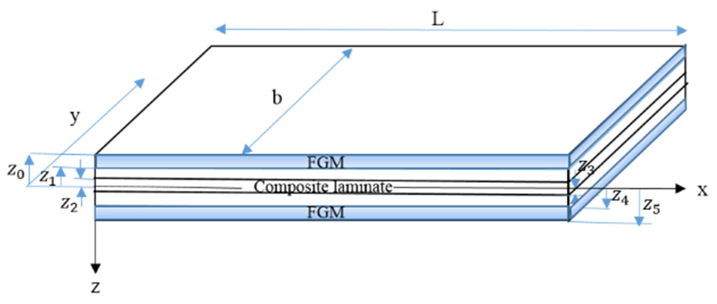
2. Theoretical Problem

Let us consider a straight composite laminated beam between two FG skins in a Cartesian coordinate system. The FG-FRCL beam has length L , uniform width b and total thickness H in x ,   y and z direction, respectively, as shown in Figure 1. The governing equations are derived under the following assumptions: (a) external layers made of FGMs with uniform thickness, h f , which are perfectly bonded on the top and bottom side of the composite laminated beam; (b) fiber-reinforced laminated core, with thickness, h c , made of n = 3 layers with the same material and different lay-ups. This means that the FG-FRCL beam is made of N = n + 2 layers; (c) Euler–Bernoulli beam assumption, thus neglecting the effect of shear deformation and rotary inertia; (d) geometric von Kármán nonlinearity; (e) uniform temperature rise Δ T . According to the Euler–Bernoulli beam theory, the cross-sections of the beam remain orthogonal to the mid-plane after beam along x ,   y and z directions, denoted by u x , u y and u z respectively.
u x x , z , t = u x , t z w x , t x
u y x , z , t = 0
u z x , z , t = w x , t
where u and w represent the displacement unknowns at the midplane along the x and z direction, respectively, w x , t x is the rotation angle of cross section about the y axis and t is the time. As mentioned before, in order to consider the geometric nonlinearity, the von Kármán strain tensor is here adopted. Based on the von Kármán strain tensor, the total nonlinear strain–displacement relationship can be defined in compact notation as follows [30,31]
ε i j = 1 2 u i x j + u j x i + u k x i · u k x j ,   i ,   j ,   k   ϵ   1 , 2 , 3
Using Equations (1)–(4), we obtain the following nonzero component of the strain tensor
ε x x = u x z 2 w x 2 + 1 2 w x 2
To model the distribution of ceramic and metal phases along the thickness of both FG layers (i.e., top and bottom layers), the rule of mixture is applied. The beam thickness is, thus, numbered from the top surface at z = z 0 , z 0 = H 2 ,   to the bottom surface at z = z 5 , z 5 = H 2 .   Based on the rule of mixture, the arbitrary Λ material properties of the FGM layers, primarily, density, ρ , modulus of elasticity, E and Poisson’s ratio, vary from pure ceramic to pure metal as follows [18]:
Λ 1 = Λ c   +   Λ m Λ c z z 5 z 4 z 5 p , z   z 4 ,   z 5 Λ 3 = Λ m   +   Λ c Λ m z z 1 z 0 z 1 p , z   z 0 ,   z 1
where Λ 1 and Λ 3 are the material properties at the bottom and top layer, respectively, indices c and m refer to the ceramic and metal phase, respectively, and p is the volume fraction exponent that indicates the material variation profile through the thickness of FG layers. In presence of a thermal load, the stress–strain relationship for the k -th layer in the axial direction is defined as
σ x k = Q 11 k ε x x α x k Δ T
In which Δ T   =   T     T 0 , is the temperature rise from the initial temperature T 0 , to temperature T. Moreover, Q 11 k and α x k represent the elastic stiffness coefficient and the thermal expansion coefficient of the k -th layer in the axial direction, respectively, and they are defined as [32].
Q 11 k = C 11 k c o s 4 ϕ + C 22 k s i n 4 ϕ + 2 C 12 k + 2 C 66 k s i n 2 ϕ c o s 2 ϕ
α x k = α 1 k c o s 2 ϕ + α 2 k s i n 2 ϕ
ϕ k being the angle of the fibers with respect to x -axis. Additionally, α 1 k and α 2 k represent the thermal expansion coefficients in the axial and lateral direction of the fibers, respectively. Moreover, C i j k , is defined as [32]
C 11 k = E 11 k 1 ϑ 12 k ϑ 21 k C 12 k = ϑ 12 k E 22 k 1 ϑ 12 k ϑ 21 k C 22 k = E 22 k 1 ϑ 12 k ϑ 21 k C 44 k = G 23 k C 55 k = G 13 k C 66 k = G 12 k ϑ 21 k = ϑ 12 k E 22 k E 11 k
where E 11 k and E 22 k stand for the modulus of elasticity, in the axial and lateral direction, G 12 k , G 13 k and G 23 k are three different shear moduli, ϑ 12 k and ϑ 21 k are two different Poisson’s ratios for the k-th ply.
For the FG layers (i.e., upper and lower layers), the normal stress σ x is defined as [33]
σ x = E z 1 ν 2 z ε x x α z Δ T
where E z , ν z and α z are defined in Equation (6). The first variation of the strain energy reads as
δ U s = V o l σ i j δ ε i j d V
Substituting Equations (5), (7) and (11) into Equation (12), we get
δ U s = b 0 L z 0 z 1 σ x δ ε x x d z d x U p p e r   l a y e r ( F G M ) + b 0 L k = 2 n = 4 z k 1 z k σ x x δ ε x x d z d x M i d d l e   l a y e r ( C o m p o s i t e   l a m i n a t e ) + b 0 L z 4 z 5 σ x δ ε x x d z d x L o w e r   l a y e r ( F G M ) = = 0 L A 11 u x + 1 2 w x 2 B 11 2 w x 2 + N T δ u x [ B 11 u x + 1 2 w x 2 D 11 2 w x 2 + M T ] δ 2 w x 2 + w x A 11 u x + 1 2 w x 2 B 11 2 w x 2 + N T δ w x d x = = 0 L { x A 11 u x + 1 2 w x 2 B 11 2 w x 2 + N T δ u + ( x A 11 u x + 1 2 w x 2 B 11 2 w x 2 + N T w x + 2 w x 2 A 11 u x + 1 2 w x 2 B 11 2 w x 2 + N T + 2 x 2 B 11 u x + 1 2 w x 2 D 11 2 w x 2 + M T δ w d x + A 11 u x + 1 2 w x 2 B 11 2 w x 2 + N T δ u | L 0 + D 11 2 w x 2 B 11 u x + 1 2 w x 2 M T δ w x | L 0 + w x A 11 u x + 1 2 w x 2 B 11 2 w x 2 + N T + x B 11 u x + 1 2 w x 2 D 11 2 w x 2 + M T δ w L 0
where
A 11 = b z 0 z 1 E ( z ) 1 ϑ 2 d z + b k = 2 n = 4 z k 1 z k Q 11 k d z + b z 4 z 5 E ( z ) 1 ϑ 2 d z             B 11 = b z 0 z 1 E ( z ) 1 ϑ 2 z d z + b k = 2 n = 4 z k 1 z k Q 11 k z d z + b z 4 z 5 E ( z ) 1 ϑ 2 z d z                       D 11 = b z 0 z 1 E ( z ) 1 ϑ 2 z 2 d z + b k = 2 n = 4 z k 1 z k Q 11 k z 2 d z + b z 4 z 5 E ( z ) 1 ϑ 2 z 2 d z                                                                                                   N T = b z 0 z 1 E z 1 ϑ 2 α z T d z b k = 2 n = 4 z k 1 z k Q 11 k α x k T d z b z 4 z 5 E ( z ) 1 ϑ 2 α z T d z                                                                                                             M T = b z 0 z 1 E z 1 ϑ 2 α z z T d z b k = 2 n = 4 z k 1 z k Q 11 k α x k z T d z b z 4 z 5 E ( z ) 1 ϑ 2 α z z T d z
The first variation of kinetic energy of the composite laminate beam is defined as [34]
δ K = 0 L b 2 b 2 k = 1 n Z k 1 Z k ρ ( k ) u t T δ u t d z d y d x
Using the displacement field in Equations (1)–(3),(15), the first variation of kinetic energy over the domain [0,T] is obtained as
0 T δ K d t = 0 T b 0 L z 0 z 1 ρ z u t T δ u t d z d x + b 0 L k = 2 n = 4 Z k 1 Z k ρ k u t T δ u t d z d x M i d d l e   l a y e r s C o m p o s i t e   l a m i n a t e U p p e r   l a y e r F G M + b 0 L z 4 z 5 ρ z u t T δ u t d z d x L o w e r   l a y e r F G M d t = = 0 T 0 L I 0 u t I 1 2 w x t δ u t I 1 u t I 2 2 w x t δ 2 w x t + I 0 w t δ w t d x d t = 0 T I 1 2 u t 2 I 2 3 w x t 2 δ w L 0 d t + 0 L I 0 u t I 1 2 w x t δ u + I 2 2 w x t I 1 u t δ w x + I 0 w t δ w T 0 d x 0 T 0 L I 0 2 u t 2 I 1 3 w x t 2 δ u + I 0 2 w t 2 + x I 1 2 u t 2 I 2 3 w x t 2 δ w d x d t
where
I 0 = b z 0 z 1 ρ z d z + b k = 2 n = 4 z k 1 z k ρ k d z + b z 4 z 5 ρ z d z
I 1 = b z 0 z 1 ρ z z d z + b k = 2 n = 4 z k 1 z k ρ k z d z + b z 4 z 5 ρ z z d z
I 2 = b z 0 z 1 ρ z z 2 d z + b k = 2 n = 4 z k 1 z k ρ k z 2 d z + b z 4 z 5 ρ z z 2 d z
The first variation of the virtual work carried out by the external forces takes the following form,
δ W E x t = 0 L F u x , t δ u + F w x , t δ w d x + N δ u + V δ w + M δ w x x = L x = 0
where F u and F w refer to the distributed external forces along x and z directions, respectively. Additionally, N , V and M stand for the axial force, transverse shear force, and bending moment, respectively, acting on the end sections of the beam. The governing equation of the system can be obtained based on the Hamiltonian principle as [35]
δ 0 T K U s + W E x t d t = 0
where δ is the variational symbol. Substituting Equations (13), (16) and (20) into Equation (21) leads to the following governing equations
x A 11 u x + 1 2 w x 2 B 11 2 w x 2 + N T + F u = I 0 2 u t 2 I 1 3 w x t 2
x A 11 u x + 1 2 w x 2 B 11 2 w x 2 + N T w x + 2 w x 2 A 11 u x + 1 2 w x 2 B 11 2 w x 2 + N T   + 2 x 2 B 11 u x + 1 2 w x 2 D 11 2 w x 2 + M T + F w = I 0 2 w t 2 + x I 1 2 u t 2 I 2 3 w x t 2
At the same time, the related boundary conditions at x = 0 and x = L are obtained as
A 11 u x + 1 2 w x 2 B 11 2 w x 2 + N T N = 0   or   δ u = 0
w x A 11 u x + 1 2 w x 2 B 11 2 w x 2 + N T + x B 11 u x + 1 2 w x 2 D 11 2 w x 2 + M T I 1 2 u t 2 I 2 3 w x t 2 V = 0   or   δ w = 0
D 11 2 w x 2 B 11 u x + 1 2 w x 2 M T M = 0   or   δ w x = 0
It is worth noticing that the differential governing equations of motion are coupled with respect to the displacement components u and w . Hence, in order to obtain a solitary equation in terms of the lateral displacement, the contribution of rotational and axial inertia is neglected [36]. Moreover, the axial and lateral loads are omitted for a free vibration analysis. Therefore, Equations (22) and (23) take the following form
x A 11 u x + 1 2 w x 2 B 11 2 w x 2 + N T = 0
x A 11 u x + 1 2 w x 2 B 11 2 w x 2 + N T w x + 2 w x 2 A 11 u x + 1 2 w x 2 B 11 2 w x 2 + N T + 2 x 2 B 11 u x + 1 2 w x 2 D 11 2 w x 2 + M T = I 0 2 w t 2
Integrating Equation (27) with respect to the x -axis gives
u x = 1 2 w x 2 + B 11 A 11 2 w x 2 1 A 11 N T + N 0 A 11
Integrating both side of Equation (29) with respect to x yields
u = 0 x 1 2 w x 2 d x + 1 A 11 N 0 N T x + B 11 A 11 w x + N 1 t
where N 0 and N 1 are two constants of integration with respect to x , that must be determined by means of different boundary conditions. In this study, we selected three types of boundary conditions, namely simply supported (S-S), clamped-clamped (C-C) and clamped-Free (C-F) boundary conditions. Thus, the boundary conditions associated with the axial displacement can be defined as [37]
u 0 , t = u L , t = 0   f o r   S S   a n d   C C   b e a m s
u 0 , t = u ( L , t ) x = 0   f o r   C F   B e a m
Using Equations (30)–(32) leads to the following expressions for S-S (or C-C) beam and C-F beam, respectively.
N 0 = A 11 L 0 L 1 2 w x 2 d x B 11 L w L , t x w 0 , t x + N T A 11 2 w L , t x 2 B 11 2 w L , t x 2 + N T N 1 = B 11 A 11 w 0 , t x   f o r   S - S ,   C - C   a n d   C - F   b e a m
By substitution of Equations (27) and (29) into Equation (28) the following differential equation for the free vibration in terms of lateral displacement, i.e., is obtained
2 x 2 B 11 2 A 11 D 11 2 w x 2 + B 11 A 11 N 0 N T + M T + N 0 2 w x 2 = I 0 2 w t 2
Since N 0 , N T and M T are constant values, Equation (37) takes the following form
I 0 2 w t 2 + D 11 B 11 2 A 11 4 w x 4 N 0 2 w x 2 = 0

3. Solution of the Nonlinear Problem

3.1. The Galerkin Method

In order to derive the ordinary differential equation of motion from the partial differential Equation (35), the Galerkin method was here adopted, according to which the displacement function w ( x , t ) can be expressed as [38]
w x , t = ψ x · ( t )
where q ( t ) is the unknown time dependent function and ψ x is the mode shape (test) function which must satisfy the kinematic boundary conditions. Based on the selected boundary conditions (S-S, C-C and C-F), the following admissible functions are considered [39,40]
ψ x = sin π x L       F o r   S - S   B e a m
ψ x = 1 2 1 c o s ( 2 π x L )       F o r   C - C   B e a m
ψ x = cos φ x L cosh φ x L κ sin φ x L sinh φ x L       F o r   C - F   B e a m
where
κ = cos φ + cosh φ sin φ + sinh φ , φ = 1.87510407
Substituting Equation (36) into Equation (35) yields
q ¨ ψ + a 1 q + a 2 q 2 + a 3 q 3 = 0
where q ¨ ( t ) is the second derivative of q ( t ) with respect to time, respectively. Additionally, the coefficients a 1 , a 2 and a 3 are defined as
a 1 = 1 I 0 D 11 B 11 2 A 11 ψ x x x x N T ψ x x ( x )
for S-S and C-C beam
a 2 = 1 I 0 B 11 L ψ x L ψ x 0 ψ x x ( x )
a 3 = 1 I 0 A 11 L 0 L 1 2 ψ x 2 d x ψ x x ( x )
and for C-F beam
a 2 = B 11 I 0 ψ x x L ψ x x x
a 3 = A 11 2 I 0 ψ x ( L ) 2 ψ x x ( x )
In which, ψ x , ψ x x , ψ x x x and ψ x x x x , are the first, second, third and fourth derivatives of ψ ( x ) with respect to x, respectively. Multiplying Equation (41) with ψ x and integrating over the domain (0,L) leads to the following nonlinear ordinary differential equation
q ¨ + ω 0 2 q + η 2 q 2 + η 3 q 3 = 0
where
ω 0 2 = 0 L a 1 ψ ( x ) d x 0 L ψ 2 ( x ) d x
η 2 = 0 L a 2 ψ ( x ) d x 0 L ψ 2 ( x ) d x
η 3 = 0 L a 3 ψ ( x ) d x 0 L ψ 2 ( x ) d x

3.2. Approximate Analytical Solution for Nonlinear Oscillation

Consider the general form of the nonlinear differential equation governing the nonlinear free oscillation as below
q ¨ + f q = 0
According to the He’s Method, the variational principle of Equation (51) can be defined by using the semi-inverse method as follows [41]
J q = 0 T 4 1 2 q ˙ 2 + F q d t
where q ˙ is the first derivative of q with respect to time, T is the period of the nonlinear oscillation and F q is a function of q . The relation between F q and f q can be defined as below [41]
F q = f ( q )
It is assumed that the approximate solution of Equation (51) can be expressed as follows
q t = A 0 cos ω n l t
where A 0 and ω n l are the amplitude and the nonlinear natural frequency of the oscillation, respectively. Substituting Equation (54) into Equation (52) and keeping in mind the transformation ω n l t = τ yields
J A 0 , ω n l = 1 ω n l 0 π 2 1 2 A 0 2 ω n l 2 s i n 2 τ + F A 0 cos τ d τ
In order to determine ω n l , the following stationary conditions based on the Ritz method should be satisfied [41]
J ω n l = 0
J A 0 = 0
It should be noted that for nonlinear oscillation, this approach will give inaccurate results. Hence, by modifying the conditions (56) and (57) into a simpler form as below, we will refer to the only condition (57).
In order to simplify the analysis, the governing Equation (48) was rewritten into the general form mentioned in Equation (51), in which, f q is
f q = ω 0 2 q + η 2 q 2 + η 3 q 3
Using of Equations (53), (54) and (58) together with the transformation ω n l t = τ leads to
F q = ω 0 2 2 A 0 2 cos 2 τ + η 2 3 A 0 3 cos 3 τ + η 3 4 A 0 4 cos 4 τ
Substituting Equation (59) into Equation (55) leads to the variational form of Equation (47) as follows
J A 0 , ω n l = 1 ω n l 0 π 2 1 2 A 0 2 ω n l 2 s i n 2 τ + ω 0 2 2 A 0 2 cos 2 τ + η 2 3 A 0 3 cos 3 τ + η 3 4 A 0 4 cos 4 τ d τ
Using Equations (57) and (60) leads to the stationary condition of Equation (60) with respect to A 0 as
J A 0 = 1 ω n l 0 π 2 A 0 ω n l 2 s i n 2 τ + ω 0 2 A 0 cos 2 τ + η 2 A 0 2 cos 3 τ + η 3 A 0 3 cos 4 τ d τ = 0
The nonlinear natural frequency of the system can be obtained from Equation (61) as follows
ω n l = ω 0 2 + 8 3 π A 0 η 2 + 3 4 A 0 2 η 3
Using Equations (36), (54) and (62) leads to the following approximate solution
w x , t = ψ x · A 0 cos ω 0 2 + 8 3 π A 0 η 2 + 3 4 A 0 2 η 3 t

3.3. Thermal Buckling Temperature

In thermoelasticity, the thermal stress occurs under the following conditions: (a) non-uniform temperature rise; (b) immovable boundary conditions even with uniform temperature rise; (c) anisotropic material, (i.e., for a plate made of several layers of different materials, even with a uniform heating) [42]. Based on these assumptions, the thermal buckling temperature, T b , of the FG-composite laminated beam with immovable boundary conditions in the axial direction (i.e., H-H and C-C) can be obtained by neglecting the contribution of ω 0 2 in Equation (48) ( ω 0 2 = 0 ) , together with the application of Equations (14), (42) and (48) as follows
T b = 0 L D 11 B 11 2 A 11 ψ x x x x ψ ( x ) d x Θ T 0 L ψ x x ψ ( x ) d x + T 0
where
Θ T = b z 0 z 1 E z 1 ϑ 2 α z d z b k = 2 n = 4 z k 1 z k Q 11 k α x k d z b z 4 z 5 E ( z ) 1 ϑ 2 α z d z

4. Numerical Results

In this section, we performed a large numerical investigation of the problem for an FG-FRCL beam subjected to a uniform temperature rise T = 50.0 , and made of five layers with width b = 0.40 m, length L = 4.0 m, total thickness H = 0.50 m, thickness of each FGM layer, h f = 0.10   m and thickness of the composite layer h c = 0.3   m . The upper and lower layers were made of an FGM varying through the thickness from a pure ceramic S i 3 N 4 to a pure metal (SUS304) with a volume fraction exponent, p = 0.40. The middle layers were made of three glass fiber-reinforced composite layers with [90/0/90] lay-ups. Additionally, the maximum amplitude of the nonlinear oscillation read as A 0 = 0.001   m . The material properties of the structure are presented in Table 1 and Table 2, in line with Refs. [18,43].
In order to validate the results of the current work, a comparison study was carried out against the available literature. The linear and nonlinear fundamental frequencies were, thus, determined from Equation (63), for simply supported composite laminated beams ( h F G = 0 ) and simply supported FGM beams ( h c = 0 ), by neglecting the thermal load. The results were obtained systematically for different values of slenderness ratio, in line with predictions by Chen and Li [34], Wang et al. [44] and Alimoradzadeh et al. [45], as reported in Table 3 and Table 4, respectively. Based on the results in these two tables, it is worth observing the high accuracy of our model against the literature due to the perfect correspondence with predictions from Refs. [34,44,45] for all slenderness ratios. It is worth observing, also, that the nonlinear fundamental frequencies were much lower that the corresponding linear ones for each slenderness ratio.
Figure 2 also plots the variation of the nonlinear natural frequency with the slenderness ratio for three different types of simply supported beams, i.e., an FGM beam (n = 1.0), an FG-FRCL beam (n = 1.0, and [90/0/90]), and a composite laminated beam ([90/0/90]). Based on these plots, the nonlinear natural frequency of the system seems to decrease for an increased slenderness ratio.
Based on the results, the FG-FRCL beams featured the highest nonlinear natural frequency, followed by FGM beams, while the composite laminated beams exhibited the lowest nonlinear natural frequency. The important point is that FG-FRCL beams are characterized by the highest nonlinear natural frequency compared with FGM beams and composite laminated beams, lighter than FGM beams and with a higher resistance against temperature rise (due to the presence of a ceramic phase) compared to composite laminated beams.
Figure 3 and Figure 4 show the effect of the power index and uniform temperature rise on the nonlinear fundamental frequency of simply supported FG-FRCL beams. As can be observed from the results, for an increased power index, the nonlinear fundamental frequency tended to increase, whose effect became more pronounced for lower slenderness ratios. At the same time, for an increased temperature, the fundamental frequency decreased, whose effect was more pronounced for increased slenderness ratios.
Figure 5 and Figure 6 represent the effect of the stacking sequence on the nonlinear natural frequency and thermal buckling temperature of simply supported FG-FRCL beams, respectively. The results demonstrate that FG-FRCL beams with [0/0/0] lay-ups exhibited the highest nonlinear natural frequency and the highest thermal buckling temperature, followed by [0/90/0] and [90/0/90] lay-ups, in sequence. A [90/90/90] lay-up, instead, provided the lowest nonlinear natural frequency and the lowest critical buckling temperature of the structure. Moreover, the results showed that the critical buckling temperature of the system increased significantly, for an increased power index.
Figure 7 represents the phase trajectory of three different types of simply supported beams including the FGM beam (n = 1.0), FG-FRCL beam (n = 1.0, and [90/0/90]) and composite laminated beam ([90/0/90]). As can be seen, the phase trajectory exhibited a limit cycle, denoting that the system was free from dynamic chaos. The results show that the velocity of the nonlinear oscillation of the FG-FRCL beams assumed the highest value, followed by FGM beams and composite laminated beams, in sequence.
Figure 8 and Figure 9 investigate the effect of the power index and temperature rise on the phase trajectory of the system with simply support boundary conditions, respectively. The results demonstrate that by increasing the power index, the phase trajectory tended to expand outward and the nonlinear oscillation velocity increased, whereas by increasing the temperature, the phase trajectory shrank inward and the nonlinear oscillation velocity decreased, while the system maintained its own stability.

5. Conclusions

This work focused on the nonlinear free vibration and thermal buckling temperature of functionally graded fiber-reinforced composite laminated (FG-FRCL) beams for three different types of boundary conditions, i.e., simply supports, clamped-clamped and clamped-free supports. The nonlinear partial differential equations associated with the problem were derived based on the Euler–Bernoulli beam theory and von Kármán geometrical nonlinearity. Such nonlinear equations were reduced to a single equation by neglecting the axial inertia. The Galerkin method was adopted to discretize the governing nonlinear partial differential equation in the form of nonlinear ordinary differential equation, which was solved analytically using a semi-inverse method to study the nonlinear free vibration time response of FG-FRCL beams. A parametric investigation focused on the effect of power-index, different lay-ups, uniform temperature rise and slenderness ratio on the nonlinear natural frequency and phase trajectory of the selected structural components. A further systematic investigation investigated the sensitivity of the thermal buckling response to different power-indexes and lay-ups. Based on such numerical investigations, the following final remarks can be summarized:
(1)
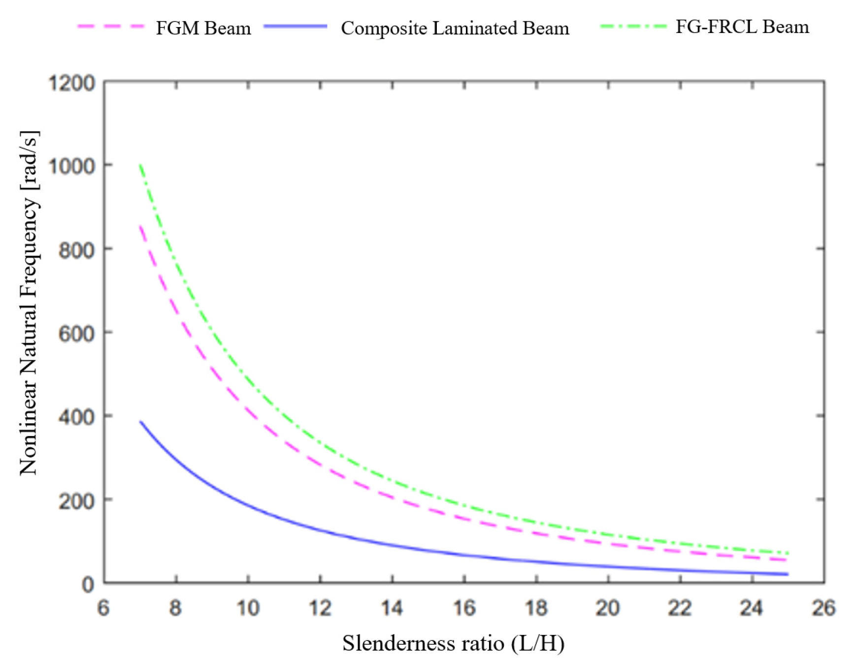
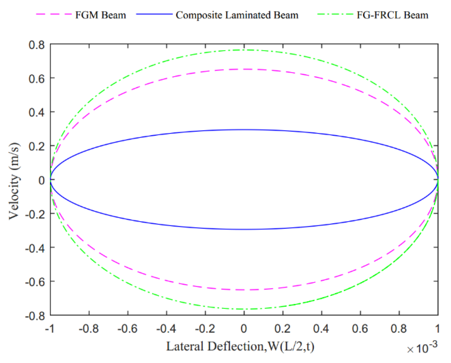
FG-FRCL beams showed the highest nonlinear natural frequency response, followed by FGM beams and composite laminated beams;
(2)
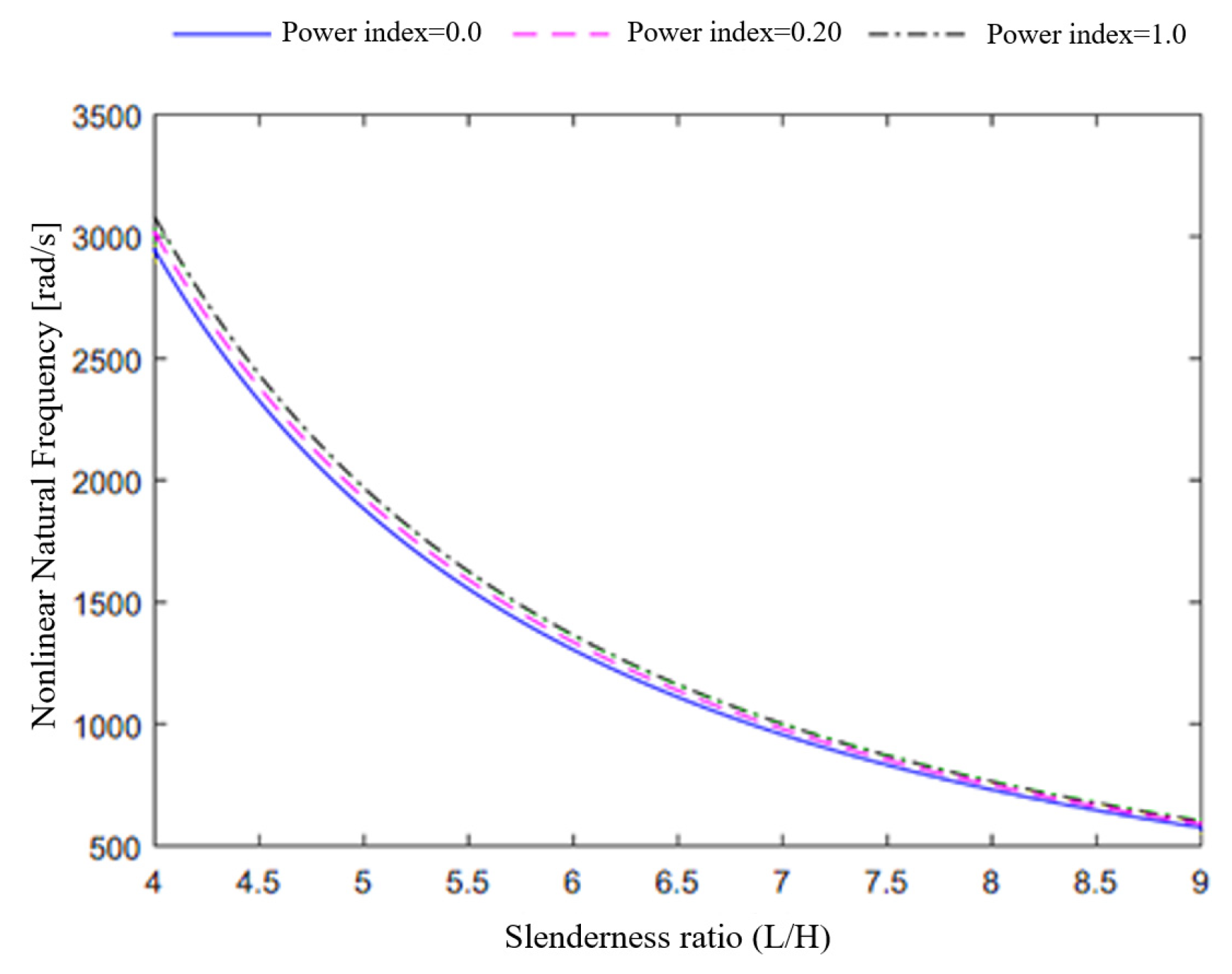
The nonlinear fundamental frequency increased for an increased power index, whose effect became more pronounced for lower slenderness ratios;
(3)
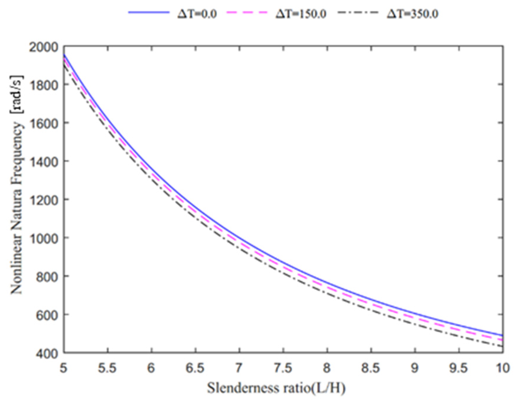
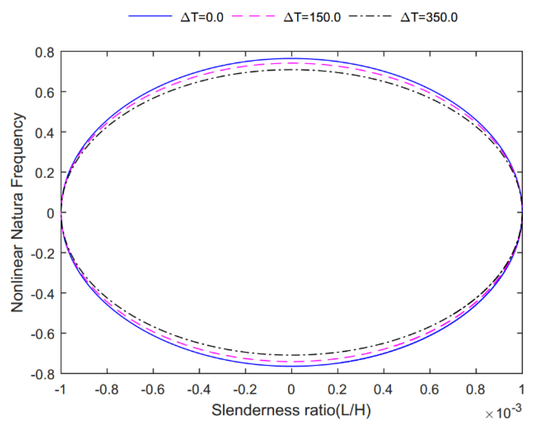
The fundamental frequency decreased for an increased temperature, especially for higher slenderness ratios;
(4)
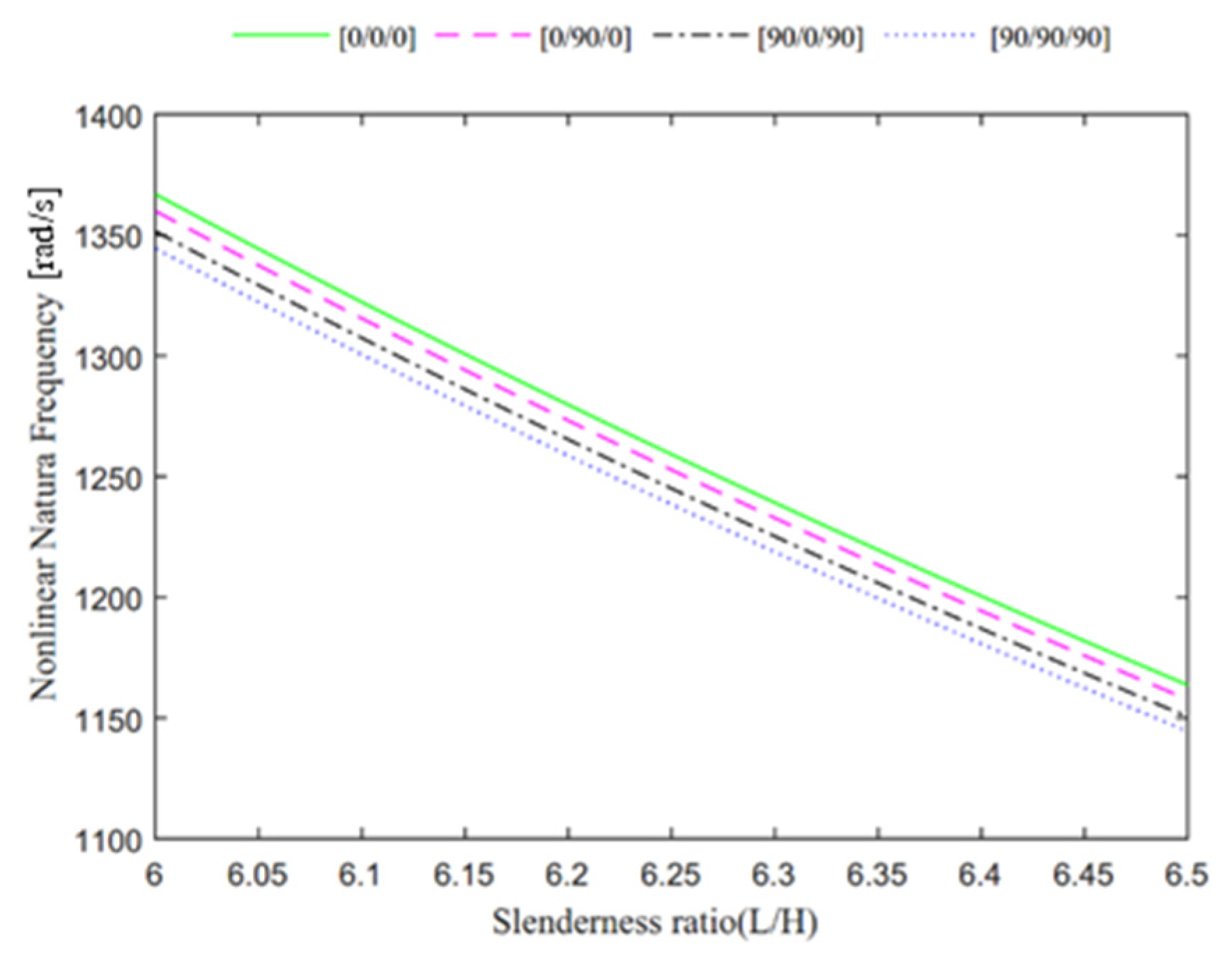
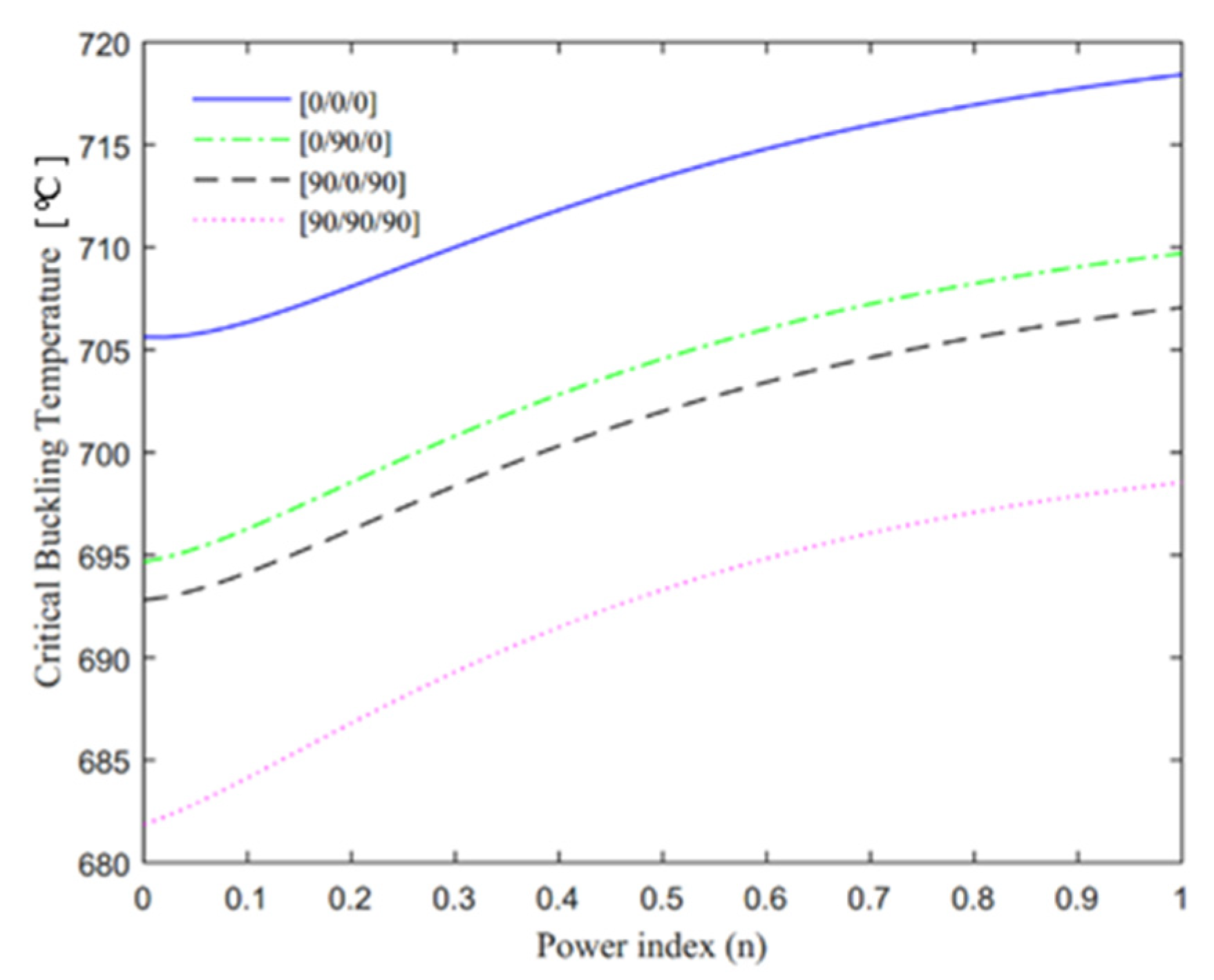
Based on a parametric evaluation of the response for different reinforcement lay-ups, FG-FRCL beams with [0/0/0] lay-ups showed the highest nonlinear natural frequency and thermal buckling temperature, followed by [0/90/0], [90/0/90] and [90/90/90] lay-ups, in sequence;
(5)
An increased power index provided an increased critical buckling temperature of the system, whereas the nonlinear oscillation velocity of FG-FRCL beams assumed the highest value followed by FGM beams and composite laminated beams, which, in turn, featured the lowest oscillation velocity;
(6)
An increased power index expanded outward the phase trajectory and yielded an increased oscillation velocity. At the same time, for an increased temperature, the phase trajectory shrank inward and the oscillation velocity decreased, while the system maintained its own stability.

Author Contributions

Conceptualization, M.A., H.H., F.T. and R.D.; Methodology, F.T. and R.D.; Validation, H.H., F.T. and R.D.; Formal analysis, M.A., F.T. and R.D.; Investigation, M.A., H.H. and R.D.; Resources, F.T.; Writing—original draft, M.A. and H.H.; Writing—review & editing, F.T. and R.D.; Supervision, F.T. and R.D. All authors have read and agreed to the published version of the manuscript.

Funding

This research received no external funding.

Conflicts of Interest

The authors declare no conflict of interest.

References

  1. Mohamed, M.; Hussein, R.; Abutunis, A.; Huo, Z.; Chandrashekhara, K.; Sneed, L.H. Manufacturing and evaluation of polyurethane composite structural insulated panels. J. Sandw. Struct. Mat. 2016, 18, 769–789. [Google Scholar] [CrossRef]
  2. Sobhani Aragh, B.; Yas, M.H. Effect of continuously grading fiber orientation face sheets on vibration of sandwich panels with FGM core. Int. J. Mech. Sci. 2011, 53, 628–638. [Google Scholar] [CrossRef]
  3. Feli, S.; Jafari, S. Analytical investigation of perforation of aluminum—Foam sandwich panels under ballistic impact. J. Modares Mech. Eng. 2013, 13, 52–59. [Google Scholar]
  4. Duc, N.D.; Seung-Eock, K.; DucTuan, N.; Tran, P.; DinhKhoa, N. New approach to study nonlinear dynamic response and vibration of sandwich composite cylindrical panels with auxetic honeycomb core layer. Aerosp. Sci. Technol. 2017, 70, 396–404. [Google Scholar] [CrossRef]
  5. Ameri, B.; Moradi, M.; Talebitooti, R. Effect of Honeycomb Core on Free Vibration Analysis of Fiber Metal Laminate (FML) Beams Compared to Conventional Composites. Compos. Struct. 2021, 261, 113281. [Google Scholar] [CrossRef]
  6. Arleo, L.; Bondì, G.; Albini, A.; Maselli, M.; Cianchetti, M. Design methodology for the development of variable stiffness devices based on layer jamming transition. Eng. Res. Express 2020, 2, 035033. [Google Scholar] [CrossRef]
  7. Tornabene, F.; Viscoti, M.; Dimitri, R.; Aiello, M.A. Higher order formulations for doubly-curved shell structures with a honeycomb core. Thin-Wall. Struct. 2021, 164, 107789. [Google Scholar] [CrossRef]
  8. Duc, N.D.; Cong, P.H. Nonlinear vibration of thick FGM plates on elastic foundation subjected to thermal and mechanical loads using the first-order shear deformation plate theory. Cogent Eng. 2015, 2, 1045222. [Google Scholar]
  9. Shen, H.-S. A comparison of buckling and postbuckling behavior of FGM plates with piezoelectric fiber reinforced composite actuators. Compos. Struct. 2009, 91, 375–384. [Google Scholar] [CrossRef]
  10. Kiani, Y.; Eslami, M.R. Thermal buckling and post-buckling response of imperfect temperature-dependent sandwich FGM plates resting on elastic foundation. Arch. Appl. Mech. 2012, 82, 891–905. [Google Scholar] [CrossRef]
  11. Lee, S.; Kim, J.H. Thermomechanical vibration and stability of effectively homogenized FGM beam with temperature-dependent shear correction factors. J. Compos. Mat. 2023, 57, 253–264. [Google Scholar] [CrossRef]
  12. Arioui, O.; Belakhdar, K.; Kaci, A.; Tounsi, A. Thermal buckling of FGM beams having parabolic thickness variation and temperature dependent materials. Steel Compos. Struct. 2018, 27, 777–788. [Google Scholar]
  13. Iurlaro, L.; Gherlone, M.; Di Sciuva, M. Bending and free vibration analysis of functionally graded sandwich plates using the Refined Zigzag Theory. J. Sandw. Struct. Mater. 2014, 16, 669–699. [Google Scholar] [CrossRef]
  14. Li, Q.; Iu, V.P.; Kou, K.P. Three-dimensional vibration analysis of functionally graded material sandwich plates. J. Sound Vibr. 2008, 311, 498–515. [Google Scholar] [CrossRef]
  15. Kong, S.; Zhou, S.; Nie, Z.; Wang, K. The size-dependent natural frequency of Bernoulli–Euler micro-beams. Int. J. Eng. Sci. 2008, 46, 427–437. [Google Scholar] [CrossRef]
  16. Shojaa, R. A micro scale geometrically non-linear Timoshenko beam model based on strain gradient elasticity theory. Int. J. Nonlinear Mech. 2012, 47, 863–873. [Google Scholar]
  17. Fernandes, R.; Mousavi, S.M.; El-Borgi, S. Free and forced vibration nonlinear analysis of a microbeam using finite strain and velocity gradients theory. Acta Mech. 2016, 227, 2657–2670. [Google Scholar] [CrossRef]
  18. Ebrahimi, F.; Jafari, A. A higher-order thermomechanical vibration analysis of temperature-dependent FGM beams with porosities. J. Eng. 2016, 2016, 9561504. [Google Scholar] [CrossRef] [Green Version]
  19. Dabbagh, A.; Rastgoo, A.; Ebrahimi, F. Thermal buckling analysis of agglomerated multiscale hybrid nanocomposites via a refined beam theory. Mech. Based Des. Struct. Mach. 2021, 49, 403–429. [Google Scholar] [CrossRef]
  20. Khorasani, M.; Lampani, L.; Dimitri, R.; Tornabene, F. Thermomechanical Buckling Analysis of the E&P-FGM Beams Integrated by Nanocomposite Supports Immersed in a Hygrothermal Environment. Molecules 2021, 26, 6594. [Google Scholar]
  21. Founda, N.; El-midany, T.; Sadoun, A.M. Bending, Buckling and Vibration of a Functionally Graded Porous Beam Using Finite Elements. J. Appl. Comput. Mech. 2017, 3, 274–282. [Google Scholar]
  22. Kamarian, S.; Salim, M.; Dimitri, R.; Tornabene, F. Free vibration analysis of conical shells reinforced with agglomerated Carbon Nanotubes. Int. J. Mech. Sci. 2016, 108–109, 157–165. [Google Scholar] [CrossRef]
  23. Zhang, L.; Lai, S.; Wang, C.; Yang, J. DSC regularized Dirac-delta method for dynamic analysis of FG graphene platelet-reinforced porous beams on elastic foundation under a moving load. Compos. Struct. 2021, 255, 112865. [Google Scholar] [CrossRef]
  24. Chen, Y.; Fu, Y.; Zhong, J.; Tao, C. Nonlinear dynamic responses of fiber-metal laminated beam subjected to moving harmonic loads resting on tensionless elastic foundation. Comp. Part B Eng. 2017, 15, 131, 253–259. [Google Scholar] [CrossRef]
  25. Xiao, B.J.; Li, X.F. Exact solution of buckling load of axially exponentially graded columns and its approximation. Mech. Res. Commun. 2019, 101, 103414. [Google Scholar] [CrossRef]
  26. Li, S.-R.; Batra, R.C. Relations between buckling loads of functionally graded Timoshenko and homogeneous Euler–Bernoulli beams. Compos. Struct. 2013, 95, 5–9. [Google Scholar] [CrossRef]
  27. Huang, Y.; Li, X.-F. Buckling Analysis of Nonuniform and Axially Graded Columns with Varying Flexural Rigidity. J. Eng. Mech. 2011, 137, 73–81. [Google Scholar] [CrossRef]
  28. von Kármán, T.; Dunn, L.G.; Tsien, H. The influence of curvature on the buckling characteristics of structures. J. Aeron. Sci. 1940, 7, 276–289. [Google Scholar] [CrossRef]
  29. von Kármán, T.; Tsien, H. The buckling of thin cylindrical shells under axial compression. J. Aeron. Sci. 1941, 8, 303–312. [Google Scholar] [CrossRef]
  30. Mandal, P.; Calladine, C.R. Buckling of thin cylindrical shells under axial compression. Int. J. Solids Struct. 2000, 37, 4509–4525. [Google Scholar] [CrossRef]
  31. Mahaffey, P.B. Bending, Vibration and Buckling Response of Conventional and Modified Euler-Bernoulli and Timoshenko Beam Theories Accounting for the von Karman Geometric Nonlinearity. Master’s Thesis, Texas A&M University, College Station, TX, USA, 2013. [Google Scholar]
  32. Daniel, I.M.; Ishai, O.; Daniel, I.M.; Daniel, I. Engineering Mechanics of Composite Materials; Oxford University Press: New York, NY, USA, 2006. [Google Scholar]
  33. Xiang, H.J.; Yang, J. Free and forced vibration of a laminated FGM Timoshenko beam of variable thickness under heat conduction. Comp. Part B Eng. 2008, 39, 292–303. [Google Scholar] [CrossRef]
  34. Chen, W.J.; Li, X.P. Size-dependent free vibration analysis of composite laminated Timoshenko beam based on new modified couple stress theory. Arch. Appl. Mech. 2013, 83, 431–444. [Google Scholar] [CrossRef]
  35. Mohammad-Abadi, M.; Daneshmehr, A.R. Modified couple stress theory applied to dynamic analysis of composite laminated beams by considering different beam theories. Int. J. Eng. Sci. 2015, 87, 83–102. [Google Scholar] [CrossRef]
  36. Samadpour, M.; Asadi, H.; Wang, Q. Nonlinear aero-thermal flutter postponement of supersonic laminated composite beams with shape memory alloys. Eur. J. Mech. A Solids. 2016, 57, 18–28. [Google Scholar] [CrossRef]
  37. Inman, D.J. Vibration with control. In Computational and Systems Oncology; John Wiley & Sons: Hoboken, NJ, USA, 2017. [Google Scholar]
  38. Norouzi, H.; Younesian, D. Chaotic vibrations of beams on nonlinear elastic foundations subjected to reciprocating loads. Mech. Res. Commun. 2015, 69, 121–128. [Google Scholar] [CrossRef]
  39. Şimşek, M. Nonlinear static and free vibration analysis of microbeams based on the nonlinear elastic foundation using modified couple stress theory and He’s variational method. Compos. Struct. 2014, 112, 264–272. [Google Scholar] [CrossRef]
  40. Laura, P.A.; Pombo, J.L.; Susemihl, E.A. A note on the vibrations of a clamped-free beam with a mass at the free end. J. Sound Vib. 1974, 37, 161–168. [Google Scholar] [CrossRef]
  41. He, J.-H. Variational approach for nonlinear oscillators. Chaos Solitons Fractals 2007, 34, 1430–1439. [Google Scholar] [CrossRef] [Green Version]
  42. Ventsel, E.; Krauthammer, T.; Carrera, E.J. Thin plates and shells: Theory, analysis, and applications. Appl. Mech. Rev. 2002, 55, B72–B73. [Google Scholar] [CrossRef]
  43. Tao, C.; Fu, Y.M.; Dai, H.L. Nonlinear dynamic analysis of fiber metal laminated beams subjected to moving loads in thermal environment. Compos. Struct. 2016, 140, 410–416. [Google Scholar] [CrossRef] [Green Version]
  44. Wang, C.M.; Ke, L.; Chowdhury, A.R.; Yang, J.; Kitipornchai, S.; Fernando, D. Critical examination of midplane and neutral plane formulations for vibration analysis of FGM beams. Eng. Struct. 2017, 130, 275–281. [Google Scholar] [CrossRef]
  45. Alimoradzadeh, M.; Akbas, S.D.; Esfrajani, S.M. Nonlinear dynamic and stability of a beam resting on the nonlinear elastic foundation under thermal effect based on the finite strain theory. Struct. Eng. Mech. 2021, 80, 275–284. [Google Scholar]
Figure 1. FG-Fiber-Reinforced Composite Laminated beam.
Applsci 13 04904 g001
Figure 2. Variation of nonlinear natural frequency versus slenderness ratio.
Applsci 13 04904 g002
Figure 3. Effect of the power index on the nonlinear fundamental frequency.
Applsci 13 04904 g003
Figure 4. Effect of the uniform temperature rise on the nonlinear fundamental frequency.
Applsci 13 04904 g004
Figure 5. Effect of stacking sequence on the nonlinear fundamental frequency.
Applsci 13 04904 g005
Figure 6. Variation of the critical buckling temperature versus power index.
Applsci 13 04904 g006
Figure 7. Phase trajectory of three different type of beams.
Applsci 13 04904 g007
Figure 8. Effect of power index on the phase trajectory.
Applsci 13 04904 g008
Figure 9. Effect of temperature rise on the phase trajectory.
Applsci 13 04904 g009
Table 1. Material properties of the FGM layers [18].
Material Properties
E(GPa) ρ ( K g m 3 ) ϑ α 1 k
Si 3 N 4 348.4323700.245.8723 × 10−6
SUS304201.0481660.326212.330 × 10−6
Table 2. Material properties of the composite layers [43].
Material Properties (Glass-Polymer Composite)
E 11 , E 22 GPa G 12 (GPa) ρ ( Kg m 3 ) ϑ 12 α 1 1 k α 2 1 k
50, 15.24.72000.00.2546.34 × 10−623.3 × 10⁻⁶
Table 3. Comparison of linear fundamental frequency.
Slenderness RatioLinear Fundamental Frequency (rad/s)
L h c Composite   Laminated   Beam   90 / 0 / 90
Present StudyReference [34]
5.01370.21370.2
10.0342.6342.6
20.085.685.6
30.038.138.1
40.021.421.4
50.013.713.7
Table 4. Comparison of linear and nonlinear fundamental frequency.
Slenderness RatioLinear Fundamental Frequency (rad/s)Nonlinear Fundamental Frequency (rad/s)
L h f FGM Beam (n = 1)FGM Beam (n = 0)
Present StudyRef. [44]Present StudyRef. [45]
5.08485.278485.35655.35655.6
10.02121.32121.31413.81413.9
20.0530.3530.3353.5353.5
30.0235.7235.7157.1157.1
40.0132.6132.688.488.4
50.084.984.956.656.6
Disclaimer/Publisher’s Note: The statements, opinions and data contained in all publications are solely those of the individual author(s) and contributor(s) and not of MDPI and/or the editor(s). MDPI and/or the editor(s) disclaim responsibility for any injury to people or property resulting from any ideas, methods, instructions or products referred to in the content.

