Abstract
Cleft lip and palate is a congenital maxillofacial deformity. Unilateral complete cleft lip and palate is one of the most common clinical types. Nasal alveolar molding (PNAM) is a recognized strategy for the treatment of cleft lip and palate. However, the current design of PNAM devices mainly relies on the subjective experience of doctors. The purpose of this paper is to describe the design and manufacture of a new computer-aided design appliance, which can be applied to the presurgical nasoalveolar molding of unilateral complete cleft lip and palate, eliminate individual differences, and improve production efficiency. In this paper, seven feature points on the healthy side and the affected side are extracted by the method of Gaussian curvature and ridge line extraction, and the healthy side rotation and built-in model are designed by using these seven feature points, which can quickly generate eight treatment stages of PNAM. The correction effects of the PNAM appliance designed in this paper were compared with the original maxillary model and the clinical PNAM appliance (hand-made by subjective experience) from the aspects of alveolar fissure width and symmetry. The PNAM appliance designed in this paper can effectively improve the symmetry of patients with unilateral complete cleft lip and palate (morphological similarity: t = 3.250, p ≤ 0.01; length similarity: t = 1.559, p = 0.150) and reduce the width of alveolar cleft (t = 8.330, p < 0.01). This can fully achieve the therapeutic effect of PNAM appliances prepared by experienced doctors and is more efficient. The method based on complex 3D surface feature point extraction can provide the basis for the design and evaluation of a unilateral complete PNAM correction model, improve the design and production efficiency of unilateral complete cleft lip and palate appliance, eliminate the design problems caused by individual differences, and reduce the burden of doctors.
1. Introduction
Cleft lip and palate is a congenital malformation of the maxillofacial region. The occurrence of congenital cleft lip and palate is affected by many factors, including heredity, environment, nutrition, and maternal infection [1]. However, the introduction, development, and application of preoperative correction techniques have effectively improved the maxillary and nasal deformities, making the dental arch and nose as normal as possible. The basic principle is that the cartilage of newborn children with cleft lip and palate has good plasticity. In 1984, Matsuo et al. [2] proposed that the high plasticity of infant cartilage is due to the high level of hyaluronic acid in infants. In infants at birth, the body’s estrogen levels are the highest, and elevated estrogen levels can increase the body hyaluronic acid content. Therefore, neonatal nasal cartilage, maxillary alveolar bone, and soft tissue around the nose and lips are highly plastic. A month after birth, the baby’s estrogen levels will gradually decline, resulting in a gradual decline in the plasticity of its cartilage. The mechanism of the PNAM appliance is based on this principle. During the period when the nasal cartilage and maxillary alveolar bone of newborn children with cleft lip and palate are highly plastic, the palatal plate is used to apply force to the displaced maxillary segment of the cleft palate. The growth of the displaced maxillary segment is guided, and the displaced maxillary segment on both sides of the cleft palate is restored to the ideal dental arch shape; we use the nasal brace on the palatal plate to guide the development of the nose, reduce the degree of external nose collapse and deflection, and try to restore the symmetry of the nose. According to the basic principle and mechanism of preoperative correction, the sooner the newborn children with cleft lip and palate are treated with PNAM after birth, the better. It is most appropriate to start PNAM treatment within 1–2 weeks after birth. Since surgical treatment cannot resolve unilateral and bilateral cleft lip and palate nasal cartilage deformities and nasal columella tissue defects in bilateral cleft lip and palate children, Grayson et al. [3,4,5] proposed PNAM in 1999 and effectively cooperated with conventional surgery to resolve nasal malformations. Kinouchi et al. [6,7,8,9,10] demonstrated that PNAM can effectively reduce the distance between the alveolar spaces and increase the height and symmetry of the nasal column. AlHayyan et al. [11] showed that PNAM did not affect the long-term midplane symmetry of the child.
PNAM has been proven to be effective in restoring normal alveolar bone structure, but the whole design process relies on the experience of physicians or operators. With the development of computer-aided technology, scholars increasingly use computer-aided technology in PNAM treatment. Schendel et al. [12] developed a computer simulation system to assist with cleft lip surgery. Wu et al. [13] used the Geomagic reverse-engineering software to arbitrarily modify and design the shape of the 3D outer nose model. Gong et al. [14,15] made the maxillary model of 10 unilateral complete cleft lip and palate children, scanned and reconstructed the model with a 3D laser scanner, and operated the maxillary 3D model by 3D diagnostic design software to simulate the whole maxillary correction process, and output the digital model for the production and processing of PNAM appliance. Shen et al. [16] presented a novel nasoalveolar molding protocol by prefabricating sets of nasoalveolar molding appliances using 3D technology. Ritschl et al. [17] integrated CAD/CAM technology for the continuous production of NAM plates for cleft palate patients. Bauer et al. [18] presented the automated RapidNAM concept that facilitates the design and manufacturing process of NAM appliances and that allows for the virtual modification and subsequent manufacture of the appliances in advance, with a growth prediction factor adapted to the patient’s natural growth. Grill et al. [19] presented a technique that combined intraoral molding with semi-automated plate generation and 3D printing. Mercan et al. [20] used computer vision to quantify the severity of nasal deformities in unilateral complete cleft lip and palate children and to compare the treatment of nasal deformities with optimal surgical outcomes. Shanbhag et al. [21] described in detail the use of dental scanners to obtain oral and maxillary models of cleft lip and palate children and the design and fabrication of PNAM orthodontics digitally using a combination of computer-aided design software and computer-aided machining. Schiebl et al. [22] revealed an algorithm for the automated generation of patient individual NAM appliances for neonates with bilateral cleft lip and palate (BCLP), and presented results of software validation. Zheng et al. [23] designed a sectional PNAM appliance using 3D printing technology and used a nasal hook simultaneously for treatment. They found that the sectional PNAM appliance can help reduce the alveolar gap, improve the shape of the nasal arch, approximate the lip segment, and significantly improve the shape of the nose by correcting flattened nasal wings. However, although the existing methods can solve the cost and time problems of NAM equipment production, they have not formed a quantifiable, automatic, and batch method system, which can only be realized by virtual modification or manual modification. Therefore, this paper is designed to find an automatic and quick computer method that can effectively reduce the burden of doctors and provide a new computer method for the study of cleft lip and palate appliances.
At present, most studies on the preoperative appliance for cleft lip and palate rely on the manual production of doctors or reverse-engineering software. The preoperative appliance for cleft lip and palate produced by these two methods shows the following shortcomings. (1) The production cycle of the appliance is long and requires the manufacturer to have certain medical experience. (2) The appliance has poor adaptability to different individuals and cannot form a quantifiable method for different individuals. The purpose of this study is to find out a quantitative and automatic design method for the preoperative appliance for unilateral complete cleft lip and palate, which is applicable to different individuals and does not depend on the experience of producers. This method relies on extracting the feature points in the cleft lip and palate model of patients to make adaptive appliances for different models. The structure of this experiment is shown in Figure 1.
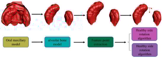
Figure 1.
Full-text structure diagram. Firstly, the alveolar bone model is extracted from the maxillary model, and then feature points are extracted from the alveolar bone model. The healthy side rotation and built-in algorithm are designed based on the extracted feature points.
2. Materials and Methods
The first part is the feature point extraction based on unilateral complete cleft lip and palate, and the second part is the design of PNAM corrector based on the feature point. All the experimental data and images are obtained through MATLAB. All procedures performed in studies involving human participants were in accordance with the Declaration of Helsinki (1964) and its later amendments or comparable ethical standards.
2.1. Data Source
The first step in both the traditional fabrication of PNAM and the computer-aided design of PNAM appliances is to obtain an oral maxillary model of the child with cleft lip and palate, which serves as the basis for designing the appliance. As the initial step in PNAM treatment for newborns with cleft lip and palate, this study elaborates on the method for preparing the maxillary model using a cooperating agency. To prepare the maxillary model for cleft lip and palate, the facebow and articulator tool depicted in Figure 2A is required. The facebow and articulator consists of external auditory canal supporting balls, nasal support, a frame adjustment frame, fixing screw, vertical connecting rod, and bite jaw fork. Its primary function is to transfer the positional relationship between the maxilla and mandible to the facebow and articulator, thereby ensuring that the oral maxillary model is fixed in the appropriate position. The specific procedure for preparing the maxillary model is as follows [24]: First, ensure that the child is fully awake. Second, insert the two external auditory canal support balls of the facebow and articulator into the child’s external auditory canal and support the nasal support at the root of the child’s nose, so that the plane composed of the external auditory canal support ball and frame adjustment frame is at the orbital ear plane. Third, apply an appropriate amount of silicone rubber to the bite jaw fork and place it in the child’s mouth, tilting the child’s head gently and allowing them to cry freely to ensure they maintain adequate breathing during the molding process. Fourth, adjust the vertical connecting rod to slowly move the bite jaw upward, ensuring to keep it parallel with the orbital plane. Finally, once the silicone rubber has solidified, remove the jaw fork to obtain the child’s oral maxillary model.
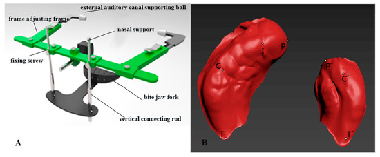
Figure 2.
(A) Schematic diagram of the facial arch. (B) Maxillary alveolar bone model feature point diagram.
The maxillary 3D model obtained in this paper was further processed by 3D design software to obtain the STL format file of the alveolar bone part in the oral maxillary 3D model of the child. STL (stereolithography) is an interface protocol developed by 3D SYSTEMS in 1988, which is a 3D graphics file format for rapid prototyping technology. The STL file is composed of the definition of multiple triangular facets. The definition of each triangular facet includes the 3D coordinates of each fixed point of the triangle and the normal vector of the triangular facet. The STL file consists of binary format or ASCII code format. The maxillary 3D models involved in this study were stored in STL files in binary format.
To read the coordinate data of the maxillary 3D model from the STL file, one must understand the form and composition of the data in the STL file. The specific composition of the STL file in binary format is as follows:
- (1)
- Part 1, 84 bytes:
The first 80 bytes are file headers, storing information such as file name; the last 4 bytes are integers describing the number of triangular patches of the model;
- (2)
- Part 2: The geometric information of all triangles is stored in order. Each triangle occupies 50 bytes, which also has its composition, followed by:
Part 1, three 4-byte floating point numbers, a total of 12 bytes, storing the x, y, and z coordinates of the triangle normal vector;
Part 2, three 4-byte floating point numbers, 12 bytes in total, storing the x, y, and z coordinates of vertex 1 of the triangle;
Part 3, three 4-byte floating point numbers, 12 bytes in total, storing the x, y, and z coordinates of vertex 2 of the triangle;
Part 4, three 4-byte floating point numbers, 12 bytes in total, storing the x, y, and z coordinates of vertex 3 of the triangle.
MATLAB is used to read the STL file of the alveolar bone part of the 3D maxillary model, read the data in the file byte by byte according to the composition of the binary STL file, and read the X, Y, and Z coordinates of vertex 1, vertex 2, and vertex 3 of each triangle surface, according to the storage order and byte length of the coordinates.
2.2. Calibration of Feature Points
Whether considering the traditional PNAM appliance or the computer-aided design PNAM appliance, the first step is to obtain the oral maxillary model of cleft lip and palate children. The 11 unilaterally intact oral maxillary model samples in this study came from STL files obtained by the partner’s 3Shape D800 3D scanner (3Shape A/S, Copenhagen, Denmark). Through the oral maxillary model, the alveolar bone of the oral maxillary model was separated by 3D Studio Max (Autodesk, San Rafael, CA, USA) drawing software. This paper mainly studies the design of an alveolar bone model appliance.
Based on these similarities, this study aims to develop a customized preoperative PNAM orthodontic device for patients with different oral structures. There are some special mark points in the alveolar bone of the unilateral complete cleft lip and palate model, which are an important basis for studying and describing the morphological characteristics of unilateral complete cleft lip and palate. For unilateral complete cleft lip and palate, after separating the alveolar bone part, the maxillary 3D model is mainly composed of the healthy side and the affected side of the alveolar cleft [25]. This mainly includes the following characteristic points:
- (1)
- Healthy side
- P: The cleft margin of the healthy side alveolar ridge;
- I: Crest of the ridge on the line drawn from the labial frenulum to the incisive papilla;
- C: The intersection point of the healthy lateral sulcus and the ridge top;
- T: The node of the healthy maxillary node is the last point of the healthy maxillary alveolus;
- (2)
- Affected sides
- P’: The cleft edge of the affected side alveolar ridge;
- C’: The location where the lateral sulcus of the affected side intersects the crest of the alveolar ridge;
- T’: The last dot of the maxillary alveolus of the affected side.
The specific locations of the feature points in the unilateral complete cleft lip and palate maxillary 3D model have been marked in the maxillary 3D model of the number sample shown in Figure 2B.
2.3. Feature Point Extraction
In the preoperative correction of unilateral complete cleft lip and palate, whether the traditional model or computer-aided design is used, each physiological feature point of the PNAM preoperative appliance needs to be marked to guide the subsequent digital design. Therefore, accurate labeling of each physiological feature point is crucial. The main features targeted in this article are T/T’, P/P’, C/C’, and I.
According to the definition of T and T’, the extraction of T and T’ can be divided into two steps:
- (1)
- Separation of the healthy side from the sick side;
- (2)
- The lowest point of the healthy side X is T, and the lowest point of the indexed side X is T’.
First of all, K-means [26] clustering is used to separate the healthy side from the sick side. The main principle of this method is to use similarity measurement to measure the relationship between all data in the data set, and to combine the closely related data into one set. The separation of the healthy side and the affected side of the 3D model is carried out by projecting the 3D data to the XOY plane and then separating them by K-means.
According to the definition of P, P’ in the previous section, point P is the cleft margin of the healthy-side alveolar ridge, and point P’ is the cleft margin of the affected side alveolar ridge. As can be seen in Figure 3A, if any point on the right side is M, the angle of sigma is MOT, and when δ is at its maximum, MOT = POT; that is, when point M is at point P, δ is at its maximum. One must find the maximum value in sigma, and then look for P, P’ values through the index of its coordinates.
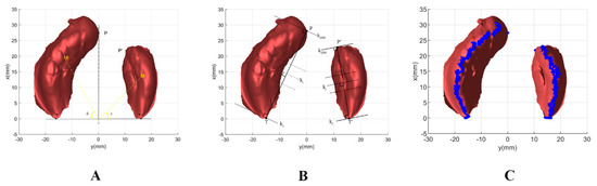
Figure 3.
(A) Extraction of feature points P and P’ diagram, based on angle method. (B) Sketch of crest line extraction from alveolar bone model of oral maxilla. (C) Results of from superimposing the extracted ridge lines onto the alveolar bone model of the oral maxilla.
According to the definition of C, I, and C’, point C is the intersection point of the healthy lateral sulcus and the ridge top, point C is the location where the lateral sulcus of the affected side intersects the crest of the alveolar ridge, and point I is the crest of the ridge on the line that is drawn from the labial frenulum to the incisive papilla. Both are concave on the alveolar ridge line, and point C’ is concave on the ridge line. Based on this, extraction of points C, I, and C’ includes the following steps:
(1) Separating the healthy side from the affected side; (2) Extracting the ridge line from the healthy side; (3) Curve fitting the points on the ridge line; and (4) Obtaining the Gaussian curvature of the points on the ridge line.
For the PNAM corrector, the method for extracting the healthy ridge is shown in Figure 3B. Make the points T and P points extracted in the previous section as H1 and H2, respectively, and then takes the vector as the normal vector to generate a set of planes. The coordinates are set as and . Then, the plane equation for the set of planes is Formula (1):
where the d of the plane set passing through the H1 coordinate point is d1 and the d of the plane set passing through the H2 coordinate point is d2. Then the di of the H1 and H2 intermediate plane set is shown in Formula (2).
where k is the number of H1, H2 intermediate plane sets, and ki the intermediate plane set i plane. The larger the size of k, the more generated planes, and the more points extracted from the ridge line, the more delicate this is; in this work, k is set to 2000. Since the ridge line is a point on the surface of the contralateral side, the above set of planes is used to intersect the contralateral side and to find the point at the top of the ridge line (i.e., the point with the smallest z coordinate). Because the model is a 3D scattered point data model, these points are not necessarily in the model, so the normal vector distance to the plane is used to determine a neighborhood, and the size of the neighborhood is slightly smaller than the normal distance between the various planes. T’, P’ is H1, H2, and the ridge line of the affected side is extracted. As shown in Figure 3C, the point set of ridges is superimposed onto the model.
This paper uses polynomial fitting to extract feature points, and the order of polynomial fitting is 5. To extract the coordinates of two points, I and C, from the ridge point set, we need to extract them according to the analysis of their morphological features.
Gaussian curvature in the discrete model is divided into two cases; internal point, and boundary point. The Gaussian curvature of the interior point is equal to 2π minus the sum of the adjacent angles of the vertex and divided by the area relative to the vertex.
The geometrical meaning of this formula is straightforward. 2π minus the angle sum of the triangle in the neighborhood of the point, then divided by the area of the corresponding region, describes the degree of curvature of the point surface. According to the definition of Gaussian curvature, the feature points extracted by the samples in this paper are all points where K(v) < 0, so the Gaussian curvature of the whole model can be solved.
Feature point C and feature point I are located in the area where the blue point is located, and points with low Gaussian curvature are more likely to be feature points. Point I is located above the highest point of the affected side, and point C is located below the affected side and above 1/3 of the height of the healthy side. Therefore, when extracting point C, we compare the Gaussian curvature of the points which are below the affected side and above 1/3 of the height of the healthy side. The smallest point is C; in the extraction of I, the points on the healthy side above the affected sideare compared, and the point with the lowest Gaussian curvature rate is I.
For the point C’, since the point C’ is located in the position of more than half of the x-coordinate of the affected side, the Gaussian curvature is calculated by the value of more than half of the x-coordinate of the affected side ridge, and the point with the minimum Gaussian curvature is obtained.
2.4. Design of PNAM Corrector Based on Feature Point
This section mainly uses the feature points extracted from the previous section to correct unilateral complete samples, mainly divided into the rotation of the healthy side and the internal construction of the healthy side. In the design of the PNAM appliance by the cooperating agency, the back end of the healthy side below point C is required to remain unchanged during the operation of the healthy side. The point I is required to be located on the median sagittal plane after rotation through the healthy side. At the same time, the front end of the healthy side above the point C has a relatively large degree of rotation and inward translation near the crack. Based on the above rules, this study achieved rotation and inward reconstruction of the healthy side.
The design scheme shown in Figure 4A takes the origin O in the XOY plane as the rotation center and the connecting line OC as the critical condition. The back end of the healthy side remains unchanged, and the front end of the healthy side rotates to the affected side and rebuilds inward. Letting M be the upper point of the healthy side, the length of the connection OM with the rotation center O is l, and the angle between OM and OT is α. It is assumed that the rotation of point M is θ, and the corresponding point of point M after rotation and inward reconstruction is M’. The length of the connection OM’ with the rotation center O is l’, and l and l’ satisfy Formula (4):
where k denotes the degree of inward modification of point M, called inward modification coefficient, and k ≤ 1. Due to the different design requirements between the front end of the healthy side and the back part and the closer the front end of the healthy side is to the crack, the greater the rotation strength and the degree of inward reconstruction—this study uses the angle α between OM and OT to control the rotation of angle θ point M and the inward reconstruction coefficient k, which follow the Formulas (5) and (6):
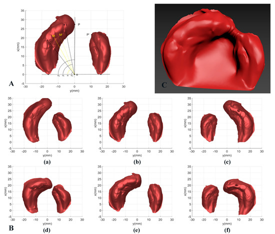
Figure 4.
(A) Schematic diagram of the sound side design of the PNAM appliance. (B) Three cases of unilateral complete sample before and after PNAM design. (a)NO. 5 (healthy side on the left) PNAM appliance before design. (b) NO. 7 (healthy side on the left) PNAM appliance before design. (c) NO. 11 (healthy side on the right) PNAM appliance before design. (d) NO. 5 (healthy side on the left) PNAM appliance after design. (e) NO. 7 (healthy side on the left) PNAM appliance after design. (f) NO. 11 (healthy side on the left) PNAM appliance after design. (C) Final PNAM appliance model of sample 7.
If we let the angle between OC and OT be αo, then the critical condition is αo. We also let the angle between OI and OT be αi, and the angle between OP and OT be αp.
According to the design requirements and the changing trend of rotation θ, f(α) should meet the following characteristics:
- (1)
- When 0 ≤ α ≤ αo, f(α) = 0 or f(α) ≈ 0, and in order to make the healthy side continuous at point C after rotation, f(α) should be derivative at α = αo;
- (2)
- When αo ˂ α ≤ αi, f(α) should be linearly or approximately linearly increasing, and at α = αi, f(α) reaches the maximum ; that is, the rotation of point I is the largest, so that I point is rotated and falls on the median sagittal plane.
- (3)
- When α > αi, f(α) should remain non-increasing.
Based on this feature, this paper proposes a robust side rotation model based on the Gaussian function. The general form of the Gaussian function is shown as Formula (7):
Where α is the angle between OM and OT; and A1, B1, and c are real constants, which represent the peak, symmetry axis, and standard deviation of the Gaussian function curve, respectively. These three parameters control the position and shape of the Gaussian function curve; On the interval , it is approximately equal to 0, on the interval , it is increasing; and on the interval , it is not increasing. The above characteristics fully meet the requirements of f(α) in Formula (4). Then, according to the Gaussian function, the angle α can control the change of the rotation θ. The key problem is realizing the mapping from the mathematical model to the physical model and determining the three parameters in the Gaussian function to realize the rotation of the healthy side reasonably and effectively.
The following rules should be followed when performing contralateral rotation on a unilateral complete cleft lip and palate sample:
- (1)
- The back end of the healthy side below point C should remain unchanged. According to the properties of the Gaussian function and 3σ principle, the critical condition is ; that is, let ;
- (2)
- Point I is rotated to the median vector plane, and the maximum rotation of point I is . Then, let , . Through the above mapping, the physical model parameters αo, αi and of the healthy side rotation are calculated by the coordinates of the calibrated point T, point C and point I in the XOY plane, and then, according to Formula (8), the three parameters of the Gaussian function , , and are as follows:
According to the design requirements and the trend of inward modification coefficient k, g(α) should satisfy the following characteristics:
- (1)
- When , or , and in order to make the reconstruction in the healthy lateral still continuous at point C, should be derivative at ;
- (2)
- When , the magnitude of the decrease should be as large as possible to restore normal dental arch morphology as a reference.
According to the above characteristics, the piecewise function is constructed, and the mathematical model is shown in Formula (9):
Since this model needs to be continuous in the defined domain, the parameters a, b during the period of are determined. It is known that passes through the two points and . To restore the alveolar bone to normal dental arch shape as much as possible as a reference, OP and OP’ should be as circular as possible, namely, OP = OP’; thus the parameters a, b, and c of this model can be calculated, as shown in Formula (10):
According to the above method, with the angle α as the variable, the rotation θ of the healthy side and the inward reconstruction coefficient k are obtained, which can be used to operate the healthy side. The rotation and inward reconstruction of the entire healthy side, as well as the translation of the affected side, are performed only in the XOY plane, i.e., without z coordinates. A point on the healthy side is set up, and the point is obtained by rotation and inward reconstruction of the healthy side. Let the plane vector of point O pointing to point M be OM and the plane vector of point O pointing point to M’ be OM’, then the relationship between the two satisfies Formulas (11) and (12):
Based on the above two characteristics, the points on the healthy side are rotated and inwardly converted into the healthy side part designed by the appliance. The combined effect is shown in Figure 4B.
After the design of the affected side and the healthy side are completed, the coordinate data are saved as a binary STL file, and the affected side and the healthy side are connected, using the 3D design software or reverse-engineering software to fill the alveolar fissure, and the whole model is smoothed. The processed model is exported as an STL file, and the final model diagram is shown in Figure 4C. Then, the final PNAM appliance model can be obtained by 3D printing technology.
2.5. Phased Design of PNAM Appliance
In the process of unilateral complete cleft lip and palate correction, the children are given staged treatment with multiple PNAM appliances to gradually achieve the purpose of correction. In this casethe patient needs to change the PNAM appliance regularly. In this study, according to the treatment plan of the cooperating agency, the whole treatment cycle was divided into eight stages, and each stage increased equally for eight weeks; that is, eight PNAM appliances were needed. The phased processing of the healthy side involves the adjustment of the relevant parameters in the healthy side rotation model and the inward reconstruction model. The principle of a PNAM appliance is to constrain and control the growth of alveolar bone, and the shape of the healthy side in all stages should be corrected. Therefore, according to the maxillary model of unilateral complete cleft lip and palate, this paper designs the final state of a PNAM appliance and obtains the parameters of the contralateral rotation model and inward reconstruction model. Then the parameters of the two models are divided into eight stages according to linearity. For example, the parameters of the contralateral rotation model in the first stage are 0.125A1, and the parameters of the inward reconstruction model are 0.125a.
3. Results and Discussion
The width of the alveolar cleft (PP’) in the maxillary model is an important index to evaluate the effect of orthodontic treatment. In the normal maxillary model, point I, point C, and point T, point C’, and point T’, the axis of point I, (namely the median sagittal plane), showed a certain degree of symmetry in the XOY plane. In the traditional PNAM appliance design method and the design method proposed in this paper, the relative position of point C, point T, point C’, and point T’ are unchanged in the design process. Therefore, this paper only describes the symmetry of the maxillary model by the position relationship between point I, point C and point C’. As shown in Figure 5A, in the XOY plane, let the distance between point I and point C be IC, and the distance along the x and y axes be ICV and ICH, respectively. Let the distance between point I and point C’ be IC’, and the distances along the x-axis and y-axis be IC’V and IC’H, respectively. Based on the above parameters, e definition are shown in Formula (13):
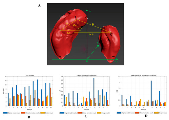
Figure 5.
(A) Symmetry map of the alveolar bone model of the oral maxilla. Comparison of PP’ (B), length similarity (C), and morphologic similarity (D), of 11 samples before, after, and after orthodontic treatment.
Among these, t describes the size relationship between IC and IC’, and s and s’ describes the shape of IC and IC’, respectively. The symmetry of the maxillary alveolar bone model is described by the size and shape of IC and IC’. When t approaches 1, the distance from point I to point C is equal to the distance from point C’, which is called length similarity. When the values of s and s’ are similar, the shape of IC and IC’ are similar, which is called shape similarity. When the values of s and s’ are close, the shapes of IC and IC’ are similar, which is called morphological similarity. At this point, the above five feature points show good symmetry, that is, the maxillary model has good symmetry. Therefore, this paper describes the symmetry of the maxillary model by calculating |1 − t| and |1 − s/s’| of the maxillary model before and after treatment. Therefore, this paper describes the symmetry of the maxillary model by calculating |1 − t|, |1 − s/s’| before, after, and after orthodontic treatment, in which |1 − s/s’| is used to describe the morphological similarity (MS) of the IC and IC’, where the smaller the value, the more similar the morphology, |1 − t| is used to describe the length similarity (LS) of the IC and the IC’, where the smaller the value, the more similar the length.
According to the original maxillary model of unilateral complete cleft lip and palate, this paper designed the PNAM appliance model in the final stage through the proposed PNAM appliance design algorithm. In this section, the design results of the PNAM appliance were compared with the original maxillary model, and the design results of the PNAM appliance were compared with the model after correctional treatment in the hospital from two aspects of alveolar fissure width and symmetry to verify that the PNAM digital design algorithm proposed in this paper can improve the correction effect of unilateral complete cleft lip and palate, which has certain application value in the clinical correction of unilateral complete cleft lip and palate. The clinical correction results mainly refer to the maxillary dental model made after wearing the appliance in the 8th stage.
As shown in Table 1 and Figure 5B–D, from the aspect of the width and symmetry of the alveolar cleft between the design results of the appliance (this study) and the original maxillary model, the width of the alveolar cleft (PP’) in the design results is significantly reduced. For the samples with high LS and MS, such as No. 3, No. 8, No. 9, and No. 10, the PNAM algorithm designed in this paper can significantly improve its symmetry. For samples with low LS and high MS, such as samples 1 and 2, the algorithm can also greatly improve its symmetry. For samples with low LS and low MS, such as No. 4, No. 5, No. 6, No. 7, and No. 11, with the exception offor samples No. 4 and No. 5, the symmetry of samples has been significantly improved. For samples No. 4 and No. 5, the algorithm designed in this paper can also improve the similarity in one of length or morphology, which will not lead to the phenomenon of symmetry imbalance, equivalent to a slight increase in the symmetry of samples. Paired t-tests were used to study the difference between the results of the original model and the results after the design. The confidence level p was 0.95. From Table 2, it can be seen that there are a total of 3 sets of matching data, PP’ shows a difference (t = 8.330, p = 0.000), MS shows a difference (t = 3.250, p = 0.009), and the difference of LS is not obvious (t = 1.559, p = 0.150), but from the mean and variance, it can be seen that there is a certain improvement. By analyzing the width and symmetry of the alveolar cleft between the design results of the appliance and the original maxillary model, it is found that the algorithm model designed in this paper has a significant improvement in both indicators. Therefore, the algorithm model designed in this paper can be effectively applied to correct unilateral complete cleft lip and palate in theory and can achieve good results.

Table 1.
Comparison of crack width and original model results, clinical correction results(clinic), and design result.
Table 2.
Statistical analysis of evaluation index of original model and design Model.
Although good results can be achieved in theory, they need to be compared to clinical data, to apply the proposed algorithm model to clinical practice. Based on this, 11 samples were corrected, and the feature points of the model after correction were extracted and compared with the algorithm model designed in this paper. As shown in Table 1, from the perspective of the width and symmetry of the alveolar fissure between the design results of the appliance (this study) proposed in this paper and the clinical correction results, for samples 3, 4, 5, 8, and 11, the reduction of the width of the alveolar fissure was significantly greater than that of the clinical correction. For samples 1, 2, 3, 8, 9, and 10, the reduction of the width of the alveolar fissure was roughly equivalent to that of the clinical correction, and only the reduction of the width of the alveolar fissure in sample 7 was less than that of the clinical correction. For length similarity, it can be seen that, except for samples 1, 5, 9, and 10, the algorithm designed in this paper performed better than clinical correction in 11 samples. For samples 1, 5, 9, and 10, the algorithm designed in this paper performed only slightly worse than clinical correction. For MS, the algorithm designed in this paper had no significant clinical correction effect on the improvement of MS, but did not significantly reduce MS. According to Table 3, it can be seen that there was no significant difference between Clinical correction results and design result when conducting t-tests based on PP’ and symmetry. Specifically, there was no significant difference in PP’ (t = 0.195, p = 0.849), MS (t = −0.659, p = 0.825), or LS (t = −1.113, p = 0.292), and the means and standard deviations of both were roughly equivalent. Therefore, it can be concluded that the design algorithm model in this paper can effectively reduce the crack width and improve the symmetry, and its effect can be completely comparable to the effect of PNAM appliance made by clinicians, or even better than that of experienced clinicians in some samples.
Table 3.
Statistical analysis of evaluation index of clinical correction results and design model.
There are still some problems with this method that need further research and solutions: (1) Standardization of the upper jaw model making process. The algorithm in this paper is based on the upper jaw alveolar bone model for design, and if there are errors in the upper jaw model making process, it will lead to unclear feature points, which will affect the subsequent algorithm design for PNAM correction. (2) Design for the growth of the affected side of the model. This method currently designs rotation and internalization methods for the healthy side, but in an actual process, the patient’s growth and development may lead to translation on the affected side. The translation distance on the affected side is related to many factors, such as the symmetry of the model and the patient’s age. Further research will be conducted to quantify the amount of translation on the affected side. (3) Targeting unilateral complete cleft lip and palate. The current algorithm in this paper mainly targets unilateral complete cleft lip and palate, and further research will be conducted on bilateral complete cleft lip and palate.
4. Conclusions
A design algorithm for unilateral complete PNAM appliances based on feature point extraction of complex surface is proposed in this paper. After extracting the alveolar bone model of patients, seven feature points of the alveolar bone model can be extracted adaptively, and eight stages of the alveolar bone model appliance are generated by using the feature points. Then the healthy and affected sides are connected and smoothed by 3D software to generate the PNAM appliance. Finally, the evaluation index of the PNAM appliance is calculated by the extracted feature points, and the correction effect of the designed PNAM appliance is compared with that of the original maxillary model and the clinical PNAM appliance made by doctors. It is provn theoretically and practically that the PNAM correction algorithm proposed in this paper can effectively improve the alveolar fissure width and symmetry of patients with unilateral complete cleft lip and palate. The method based on complex 3D surface feature point extraction can provide the basis for the design and evaluation of a unilateral complete PNAM correction model, eliminate the design problems caused by individual differences, and reduce the burden of doctors.
Author Contributions
L.L. collected the research data and directed the experiment. T.L. conducted the design of the experiment and the writing of the manuscript. D.F. was involved in statistical analysis. All authors have read and agreed to the published version of the manuscript.
Funding
The work was supported by funding from “Smile Train”.
Institutional Review Board Statement
All procedures performed in studies involving human participants were in accordance with the Ethics Committee of the School of Stomatology, Wuhan University (Approval 2019-B15) and with the 1964 Helsinki declaration and its later amendments or comparable ethical standards. Informed consent was obtained from all individual participants included in the study.
Informed Consent Statement
Informed consent was obtained from all subjects involved in the study.
Data Availability Statement
As the data were obtained from the Orthodontic Department of the Hospital of Stomatology Wuhan University, and the consent of the Orthodontic Department of the Hospital of Stomatology Wuhan University was required for data acquisition and publication, the data sets generated and/or analyzed during the current study were not publicly available, but could be obtained from the appropriate authors upon reasonable request.
Acknowledgments
Thanks to “Smile Train” for funding and the data set and guidance provided by the orthodontic Department of the Hospital of Stomatology Wuhan University.
Conflicts of Interest
The authors declare no conflict of interest.
References
- Vanderas, A.P. Incidence of cleft lip, cleft palate, and cleft lip and palate among races: A review. Cleft Palate J. 1987, 24, 216–225. [Google Scholar]
- Matsuo, K.M.; Hirose, T.M.; Tomono, T.M.; Iwasawa, M.M.; Katohda, S.M.; Takahashi, N.M.; Koh, B.M. Nonsurgical correction of congenital auricular deformities in the early neonate: A preliminary report. Plast. Reconstr. Surg. 1984, 73, 38–50. [Google Scholar] [CrossRef] [PubMed]
- Grayson, B.H.; Cutting, C.; Wood, R. Preoperative columella lengthening in bilateral cleft lip and palate. Plast. Reconstr. Surg. 1993, 92, 1422–1423. [Google Scholar] [PubMed]
- Grayson, B.H.; McCormick, S.; Santiago, P.E.; McCarthy, J.G. Vector of device placement and trajectory of mandibular dis-traction. J. Craniofacial Surg. 1997, 8, 473–480. [Google Scholar] [CrossRef]
- Grayson, B.H.; Santiago, P.E.; Brecht, L.E.; Cutting, C.B. Presurgical Nasoalveolar Molding in Infants with Cleft Lip and Palate. Cleft Palate-Craniofacial J. 1999, 36, 486–498. [Google Scholar] [CrossRef]
- Kinouchi, N.; Horiuchi, S.; Yasue, A.; Kuroda, Y.; Kawai, N.; Watanabe, K.; Izawa, T.; Hashimoto, I.; Hassan, A.H.; Tanaka, E. Effectiveness of presurgical nasoalveolar molding therapy on unilateral cleft lip nasal deformity. Saudi Med. J. 2018, 39, 169–178. [Google Scholar] [CrossRef] [PubMed]
- Liang, Z.; Yao, J.; Chen, P.K.; Zheng, C.; Yang, J. Effect of presurgical nasoalveolar molding on nasal symmetry in unilateral complete cleft lip/palate patients after primary cheiloplasty without concomitant nasal cartilage dissection: Early childhood evaluation. Cleft Palate-Craniofacial J. 2018, 55, 935–940. [Google Scholar] [CrossRef]
- Dinh, T.T.N.; Van Nguyen, D.; Dien, V.H.A.; Dong, T.K. Effectiveness of Presurgical Nasoalveolar Molding Appliance in Infants with Complete Unilateral Cleft Lip and Palate. Cleft Palate-Craniofacial J. 2022, 59, 995–1000. [Google Scholar] [CrossRef] [PubMed]
- Fuchigami, T.; Kimura, N.; Kibe, T.; Tezuka, M.; Amir, M.S.; Suga, H.; Takemoto, Y.; Hashiguchi, M.; Maeda-Iino, A.; Nakamura, N. Effects of pre-surgical nasoalveolar moulding on maxillary arch and nasal form in unilateral cleft lip and palate before lip surgery. Orthod. Craniofacial Res. 2017, 20, 209–215. [Google Scholar] [CrossRef] [PubMed]
- Trivosa, V. The Impacts and Outcomes of Presurgical Nasoalveolar Molding (PNAM) in Newborn Sequential Therapeutic Implementation. J. Dent. Oral Sci. 2021, 3, 1–10. [Google Scholar] [CrossRef]
- AlHayyan, W.A.; Pani, S.C.; AlJohar, A.J.; AlQatami, F.M. The Effects of Presurgical Nasoalveolar Molding on the Midface Symmetry of Children with Unilateral Cleft Lip and Palate: A Long-term Follow-up Study. Plast. Reconstr. Surg. Glob. Open 2018, 6, 1764. [Google Scholar] [CrossRef] [PubMed]
- Schendel, S.; Montgomery, K.; Sorokin, A.; Lionetti, G. A surgical simulator for planning and performing repair of cleft lips. J. Cranio-Maxillofac. Surg. 2005, 33, 223–228. [Google Scholar] [CrossRef] [PubMed]
- Wu, G.; Zhou, B.; Bi, Y.; Zhao, Y. Selective laser sintering technology for customized fabrication of facial prostheses. J. Prosthet. Dent. 2008, 100, 56–60. [Google Scholar] [CrossRef] [PubMed]
- Gong, X.; Yu, Q. Correction of maxillary deformity in infants with bilateral cleft lip and palate using computer-assisted design. Oral Surgery, Oral Med. Oral Pathol. Oral Radiol. 2012, 114, S74–S78. [Google Scholar] [CrossRef]
- Yu, Q.; Gong, X.; Shen, G. CAD presurgical nasoalveolar molding effects on the maxillary morphology in infants with UCLP. Oral Surgery, Oral Med. Oral Pathol. Oral Radiol. 2013, 116, 418–426. [Google Scholar] [CrossRef]
- Shen, C.; Yao, C.A.; Magee, W.; Chai, G.; Zhang, Y. Presurgical nasoalveolar molding for cleft lip and palate: The application of digitally designed molds. Plast. Reconstr. Surg. 2015, 135, 1007e–1015e. [Google Scholar] [CrossRef]
- Ritschl, L.M.; Rau, A.; Güll, F.D.; Dibora, B.; Wolff, K.-D.; Schönberger, M.; Bauer, F.X.; Wintermantel, E.; Loeffelbein, D.J.; Ritschl, L.M.; et al. Pitfalls and solutions in virtual design of nasoalveolar molding plates by using CAD/CAM technology—A preliminary clinical study. J. Cranio-Maxillofac. Surg. 2016, 44, 453–459. [Google Scholar] [CrossRef]
- Bauer, F.X.; Schönberger, M.; Gattinger, J.; Eblenkamp, M.; Wintermantel, E.; Rau, A.; Güll, F.D.; Wolff, K.-D.; Loeffelbein, D.J. RapidNAM: Generative manufacturing approach of nasoalveolar molding devices for presurgical cleft lip and palate treatment. Biomed. Eng./Biomed. Tech. 2017, 62, 407–414. [Google Scholar] [CrossRef]
- Grill, F.D.; Ritschl, L.M.; Bauer, F.X.; Rau, A.; Gau, D.; Roth, M.; Eblenkamp, M.; Wolff, K.-D.; Loeffelbein, D.J. A semi-automated virtual workflow solution for the design and production of intraoral molding plates using additive manufacturing: The first clinical results of a pilot-study. Sci. Rep. 2018, 8, 11845. [Google Scholar] [CrossRef]
- Mercan, E.; Morrison, C.S.; Stuhaug, E.; Shapiro, L.G.; Tse, R.W. Novel computer vision analysis of nasal shape in children with unilateral cleft lip. J. Cranio-Maxillofac. Surg. 2018, 46, 35–43. [Google Scholar] [CrossRef]
- Shanbhag, G.; Pandey, S.; Mehta, N.; Kini, Y.; Kini, A. A Virtual Noninvasive Way of Constructing a Nasoalveolar Molding Plate for Cleft Babies, Using Intraoral Scanners, CAD, and Prosthetic Milling. Cleft Palate-Craniofacial J. 2020, 57, 263–266. [Google Scholar] [CrossRef] [PubMed]
- Schiebl, J.; Bauer, F.X.; Grill, F.; Loeffelbein, D.J. RapidNAM: Algorithm for the Semi-Automated Generation of Nasoalveolar Molding Device Designs for the Presurgical Treatment of Bilateral Cleft Lip and Palate. IEEE Trans. Biomed. Eng. 2020, 67, 1263–1271. [Google Scholar] [CrossRef]
- Zheng, J.; He, H.; Kuang, W.; Yuan, W. Presurgical nasoalveolar molding with 3D printing for a patient with unilateral cleft lip, alveolus, and palate. Am. J. Orthod. Dentofac. Orthop. 2019, 156, 412–419. [Google Scholar] [CrossRef] [PubMed]
- Zheng, J.; He, H.; Kuang, W.; Yuan, W. Novel Three-Dimensional Coordinate System to Analyze Alveolar Molding Effects of Pre-Surgical Nasoalveolar Molding on Infants with Non-Syndromic Unilateral Cleft Lip and Palate. J. Craniofacial Surg. 2020, 31, 653–657. [Google Scholar] [CrossRef] [PubMed]
- Braumann, B.; Keilig, L.; Bourauel, C.; Jäger, A. Three-Dimensional Analysis of Morphological Changes in the Maxilla of Patients with Cleft Lip and Palate. Cleft Palate-Craniofacial J. 2002, 39, 1–11. [Google Scholar] [CrossRef]
- Yuan, C.; Yang, H. Research on K-Value Selection Method of K-Means Clustering Algorithm. J. Multidiscip. Sci. J. 2019, 2, 226–235. [Google Scholar] [CrossRef]
Disclaimer/Publisher’s Note: The statements, opinions and data contained in all publications are solely those of the individual author(s) and contributor(s) and not of MDPI and/or the editor(s). MDPI and/or the editor(s) disclaim responsibility for any injury to people or property resulting from any ideas, methods, instructions or products referred to in the content. |
© 2023 by the authors. Licensee MDPI, Basel, Switzerland. This article is an open access article distributed under the terms and conditions of the Creative Commons Attribution (CC BY) license (https://creativecommons.org/licenses/by/4.0/).