Article

Electrified Powertrain Development: Distributed Co-Simulation Protocol Extension for Coupled Test Bench Operations

1
Institute of Vehicle System Technology, Karlsruhe Institute of Technology, Rintheimer Querallee 2, 76131 Karlsruhe, Germany
2
Institute of Internal Combustion Engines, Karlsruhe Institute of Technology, Rintheimer Querallee 2, 76131 Karlsruhe, Germany
3
Institute of Electrical Engineering, Karlsruhe Institute of Technology, Engelbert-Arnold-Straße 5, 76131 Karlsruhe, Germany
4
APL Automobil-Prüftechnik Landau GmbH, Am Hölzel 11, 76829 Landau, Germany
*
Author to whom correspondence should be addressed.
Appl. Sci. 2023, 13(4), 2657; https://doi.org/10.3390/app13042657
Submission received: 12 January 2023 / Revised: 9 February 2023 / Accepted: 14 February 2023 / Published: 18 February 2023
(This article belongs to the Special Issue Developments and Advancements for Electric and Hybrid Vehicles)

Abstract

:
The increasingly stringent CO2 emissions standards require innovative solutions in the vehicle development process. One possibility to reduce CO2 emissions is the electrification of powertrains. The resulting increased complexity, as well as the increased competition and time pressure make the use of simulation software and test benches indispensable in the early development phases. This publication therefore presents a methodology for test bench coupling to enable early testing of electrified powertrains. For this purpose, an internal combustion engine test bench and an electric motor test bench are virtually interconnected. By applying and extending the Distributed Co-Simulation Protocol Standard for the presented hybrid electric powertrain use case, real-time-capable communication between the two test benches is achieved. Insights into the test bench setups, and the communication between the test benches and the protocol extension, especially with regard to temperature measurements, enable the extension to be applied to other powertrain or test bench configurations. The shown results from coupled test bench operations emphasize the applicability. The discussed experiences from the test bench coupling experiments complete the insights.

1. Introduction

Since 2021, the new EU CO2 emissions standards have required passenger car fleets not to exceed 95 g of CO2 per kilometer on average. As an additional constraint, a more realistic test procedure (Worldwide harmonized Light-duty vehicles Test Procedure, WLTP) was introduced, with pollutant emissions also being measured on the road (Real Driving Emissions, RDE). By 2030, the European Union demands a further reduction in CO2 emissions by 37.5%. Ongoing discussions of the European Green Deal involve even more ambitious emissions reduction targets [1].
This legal framework enhances the trend towards electrified vehicles. The potential contribution of different electrified powertrain types to the reduction in emissions is being investigated in various studies [2,3]. Possible powertrain types are, for example, hybrid electric vehicles (HEV), which combine an internal combustion engine (ICE) as well as an electric powertrain including electric machine (EM), power electronics, and a battery. Owing to increased complexity, the hybrid drivetrain’s development requires a large amount of effort, both in design and testing. To meet these demands, suitable toolchains need to be employed. In this context, X-in-the-Loop methods play an important role, complemented by recent developments in Distributed Co-Simulation, as described in Section 2.
In the early development phase, such component, functional and full powertrain concepts can be evaluated and optimized a long time before a prototype vehicle is available. The possibility of variable conditioning of a basic unit for simulated use in vehicles of different flywheel mass classes holds considerable potential in this context, especially in view of the modular drive concepts (modular construction systems) that are increasingly being used across different vehicle segments.
In the context of the Euro 7 standard, the focus is also on a wider temperature range in the extended driving conditions from −10 °C to 45 °C. In addition to road tests, a wide range of investigations must be carried out on component, powertrain and vehicle test benches in this context. In contrast to testing the full vehicle on a chassis dynamometer, alternative test benches with powertrain components offer the advantage that the media temperatures can be controlled very quickly and reproducibly to the cycle start temperatures for cold start tests. Compared to the test duration in which the vehicles are conditioned in special areas, this results in a time advantage by a factor of up to 10 in practice.
The aim of the research presented in the Refs. [4,5] as well as in this publication was to develop a generally applicable methodology for coupling test benches using the example of a hybrid powertrain. This was demonstrated in a novel setup of co-operating internal combustion and electric engine test benches. A system-oriented operation strategy was applied, while considering various component boundary conditions, such as the influence of temperatures. The methodology itself enables an intermediate step in the development process, which allows for frontloading of test procedures from the system level to the component level. This additional possibility to increase test bench utilization also results in time and cost savings. The reduced effort compared to the physical coupling of the machines also enables more flexible testing of different powertrain components in combination, as the coupling is only implemented through software. A vehicle manufacturer, for example, can thus already test the interaction of individual components from different suppliers before a configuration has to be set.
Some test procedures are shown in Figure 1 as a function of the time required to perform and the overall system’s development progress which is required. The five test case areas of thermal behavior, system application, system performance, system efficiency, and functional safety can, for example, be advanced by means of virtually coupled test benches, and have been investigated in this research as test case examples.
Compared to the existing literature, this work extends the Distributed Co-Simulation Protocol (DCP) Standard to allow for the coupling of EM and ICE test benches to test electrified powertrains. Special effort is put on different technical boundary conditions for simple integrability and a high level of safety. These aspects aim for the development of a method to implement virtual coupling capabilities on existing test benches that are ready for field application.

2. Related Work

2.1. X-in-the-Loop Methodology in Powertrain Development

Over the years, more and more development tasks have been virtualized in order to save time and costs related to protracted testing of numerous hardware variants that are otherwise required. This trend is also reflected in the most recent update of the standard VDI/VDE 2206, which provides guidelines for the “development of mechatronic and cyber-physical systems” [6]. Here, the development is visualized by the V model, which arranges development tasks, such as requirements engineering, development of the system architecture, implementation of elements, and subsequent integration and validation. The entire process is accompanied by modeling and analysis. At the beginning, this involves models of entire vehicles, including submodels, such as the powertrain and its components. As development proceeds, hardware is integrated step-by-step into the simulation loop. In this context, the term X-in-the-Loop (XiL) was created. Applications range from Model- (MiL) and Software-in-the-Loop (SiL) towards Hardware-in-the-Loop (HiL), Engine-in-the-Loop (EiL), and Vehicle-in-the-Loop (ViL). In the case of EiL, a vehicle simulation is set up, including subsystems, environment, and driver behavior. As implied by the name, the engine is not represented by a model, but a real test specimen installed at a test bench (TB). This approach allows engine tests in a relatively realistic environment. Ideally, an entire XiL toolchain is employed, which allows the subsequent integration and testing of hardware and software.

2.2. Distributed Powertrain Development

Powertrain development involves several participants, working at both the original equipment manufacturer (OEM) and supplier levels. Thus, development tasks are distributed both temporally and geographically within and across companies. Nevertheless, subsystems, such as the ICE or the gearbox, may only be tested separately, until the later assembly of the subsystems in the development process. At this point, recent approaches of so-called Distributed Real-Time (RT) Co-Simulation methods can be applied.
One of the main ideas is to couple test benches that cooperate with each other to perform tests at a higher system integration level at early component development stages. In the case of powertrain development, this might involve tests on ICE and EM test benches to examine hybrid powertrains. In this context, several projects were set up. An overview of the related literature is provided in the following subsections.

2.2.1. Distributed Co-Simulation Protocol

From 2015 to 2018, several companies and universities cooperated in the project known as Advanced Co-Simulation Open System Architecture (ACOSAR). The objective was to enable the combination of virtual and real subsystems to perform cyber-physical tests at early development stages, resulting in the DCP Standard. Later, the standard was transferred into a Modelica Association Project (MAP). In the context of the Open Systems Interconnection (OSI) model and its protocol stack, the DCP can also be seen as an open-standard application layer communication protocol [7].

General Protocol Working Principle

The ACOSAR project’s final report [8] gives information on the objectives, project phases, and results. This includes a literature review, dealing with different simulation types, RT systems, communication media, relevant tools, and related projects [9].
The protocol follows a master–slave principle, including one master and one or more slaves. Distributed Co-Simulation scenarios might consist of HiL systems, test benches, or simulation tools. Both the master and slave require a state machine, which communicate via Protocol Data Units (PDUs). This procedure is based partly on the definition of the Functional Mock-up Interface (FMI), another standard specified by Modelica. The basic elements of the standard are described in the specification document (Version 1.0) [10], particularly with regard to the slave implementation. The configuration of slaves is further described in the Ref. [11].
In the Ref. [12], the authors gave a short insight into the main design ideas of the DCP (interoperability, integration, compatibility, communication, economy), as well as the tools, protocols, and communication architecture. Three different operating modes and their respective time domains are presented: non-real-time (NRT), soft real-time (SRT), and hard real-time (HRT). The modes can be used depending on the chosen communication protocol. For HRT operation, an EtherCAT connection might be used. The communication can also be realized via TCP/IP (see, for example, the specification document [10]).

Master Implementation

While the DCP specification document mainly focuses on the slave implementation, more information about the master is given in an additional publication [13]. Several requirements are listed regarding communication, real time, integration of DCP slaves, reliability, configuration and state monitoring, and simulation cycle phases. A master state machine is proposed also. Both master and slave state machine literature implementations served as a template of the state machines realized in this project, see Section 3.3.

Synchronization

Some features are not yet included in Version 1.0 of the DCP standard, such as clock synchronization. In the Ref. [7], the authors discussed different clock synchronization mechanisms. These might be required if DCP participant clocks differ in the ratio of speed and offset, resulting in the oversampling or undersampling of variables. A synchronization approach is implemented in the present work, see Section 3.3.

Verification

Incorrectly defined DCP slaves might result in avoidable costs as well as damage in experiments involving hardware. For these reasons, the authors in [14] show a verification approach, which follows the V model. For testing, the DCP Test Generator and the DCP Tester have been developed. Both tools are openly accessible on GitHub including white-paper documentation. In a vehicle simulation and engine test bench co-simulation scenario, the authors successfully demonstrated tool functionality.

Requirements and Model-Based Systems Engineering

In the Ref. [15], the authors discussed the challenges that arise from the development of consistent technical standards or specifications, as different stakeholders (e.g., OEMs, suppliers, research institutes) from various sectors (automotive, maritime, automation) might be involved. As a solution, process artifacts are proposed, which are defined at different levels.
As soon as multiple, diverse co-simulation scenarios are to be investigated, efficient configuration and commissioning becomes increasingly important. To this end, the authors in the Ref. [16] proposed a domain-specific modeling language, the so-called Distributed Co-Simulation Protocol Modeling Language (DCPML).
In the Ref. [17], the aforementioned concepts were further developed into a Process Model for Efficient Distributed Co-Simulation (ProMECoS). This model relates to the standard IEEE 1730, which recommends practices for distributed simulation engineering and execution. The authors indicate the high automation potential of ProMECoS, but also mention several limitations regarding integration into architecture models (e.g., AUTOSAR), master algorithms, and further transport protocols.

2.2.2. Test Bench Coupling Publications

Apart from the literature directly related to the ACOSAR project, other publications in the area of test bench coupling were identified that are related to projects and approaches, such as ACoRTA, XiL-BW-e, TechReaL, Virtual shaft, and so forth. In Table 1, the literature is summarized and categorized by project or approach affiliation.

3. Materials and Methods

3.1. Development Environment

For the results of the coupled test benches example presented in this paper, a vehicle simulation of a parallel P2 hybrid was set up to generate a suitable environment for the coupled test benches. Gas and brake pedal positions are calculated from a driver model, developed and validated for a driving robot on a full vehicle test bench [51]. As a result, control problems due to inertias in the powertrain or latencies caused by test bench communication can be avoided. The resulting load requirements are acquired by a hybrid controller and distributed to the two test benches depending on the operating modes. The rule-based hybrid controller has common operating modes, such as load point shifting, electric driving, engine driving, and boost. For the ICE, values for the accelerator pedal position, and for the EM, values for the torque requirements are calculated. The torques provided by the test benches are combined by a detailed transmission model and transmitted to the road via the differential and the wheels to calculate subsequent vehicle conditions. A detailed gearbox model is needed to perform temperature calculations, because the real EM and the virtual gearbox had a cooling circuit connected in parallel. The measured EM temperature and the gearbox temperature calculated from the gear losses are then used to calculate the cooling fluid’s inlet temperature and transmitted to the EM test bench’s conditioning system as a reference value. For the EM, a battery model consisting of an equivalent circuit with two RC elements was also built to calculate the state-of-charge (SoC) dependent DC link voltage. The battery model, as well as the transmission model and some hybrid controller conditions were derived from the reference vehicle’s measurement data. Regarding the developed vehicle simulation models, a transition from simulation-only to test bench experiments needs to be guaranteed, including adequate interface identification and configuration. For this case, the models were prepared step-by-step in a simulation toolchain for application on the test bench. MiL and SiL approaches were used, and the HiL method was then applied to validate the models with the separate test benches ensuring the usage for coupled test bench operation.

3.2. Test Bench Setup

In the following Section, an overview of the two component test benches used in this work is given. Information on the test sites’ interconnection is provided in Section 3.3 and Section 3.4. The individual test bench setups represent test benches that can be found in many applications. Nevertheless, for better traceability and to avoid misunderstandings, the test benches are explained in detail in the following sections.

3.2.1. Electric Machine Test Bench

The electric machine test bench can be divided into several subsystems, the active front-end with an integrated battery simulator and an AC inverter for the load machine. A temperature control subsystem is used to satisfy the thermal conditioning of the device under test (DUT). The temperature control subsystem’s setup is detailed in the Ref. [4]. In addition, to meet the requirements for a coupled test bench operation, there is a superimposed RT system test bench control unit (TCU) for overall test bench control and the necessary communication for coupling. The schematic setup of the test bench is shown in Figure 2. The performance data of the subsystems is listed in Table 2.

Functionalities

The following describes the subsystems’ functionalities.
1.
Active front-end, battery simulator, and load machine inverter
This subsystem represents the interface of the test bench to the grid. The battery simulator rectifies and converts the grid voltage to a variable DC link voltage in a first DC link with the aid of the active front-end subsystem. The voltage is then variably reduced from this first high-voltage DC link to a second DC link with the aid of a buck converter subsystem. Characteristic curves can also be stored in the buck converter so that the voltage can be adjusted depending on the operating point. Battery behavior can thus be simulated. See [52] for a more detailed description of the battery simulator. The inverter for the test bench’s load machine is also supplied from the first intermediate circuit of higher voltage. A real-time control system and various internal measurement devices with limit value monitoring and emergency shutdown are used to control the subsystems listed.
2.
Load machine
The test bench’s load machine is statically connected to the machine bed, and various test specimens can be mounted via a fixture. The shafts of the two machines are connected with the EK6 elastomer coupling from R+W Servomax. This permits the assembly and operation of a wide range of different electrical machines on the test bench. A torque measuring shaft (Manner Sensortelemetrie, type 500 N m ) and a speed measuring device are also be permanently installed.
3.
Automotive AC inverter and machine
This inverter has semiconductors from the automotive sector. The subsystem is supplied by the battery simulator and operates the device under test. For the research, a prototype hybrid machine of an OEM was mounted on the test bench as the DUT.
4.
Superimposed real-time system test bench control unit
The control and regulation of all subsystems and thus of the entire test bench was carried out by the TCU at 10 k Hz . This real-time system (dSpace MicroLabBox) connects the interface to a host PC and thus allows for user communication. The measurement data of all sensors also converge in this real-time system and can be recorded at 2– 10 k Hz and viewed centrally.
5.
Temperature control system
The DUT temperature can be controlled separately by a temperature control device. The performance data are listed in Table 3. Furthermore, the test bench can be extended by adding more temperature control devices for the components exposed to a variable temperature in the vehicle. The temperature control devices control the component temperature by modifying the temperature and the volume flow, as dictated by the superimposed real-time system.
Due to the decreasing temperature difference between the cooling medium and the primary cooling circuit during cooling, the time required for temperature control to lower temperatures is very high. This is irrelevant for normal vehicle operation, but must nevertheless be considered, in particular when tempering to an initial temperature at the start of the test run.

Software Extension of the Test Bench

In addition to the test bench hardware, the software also plays an important role. For the hybrid powertrain simulation, a software extension with vehicle-specific algorithms may be necessary. For instance, in the case of the EM test bench for controlling the DUT, the machine is characterized in order to consider the non-linear EM behavior when controlling the EM. In addition, for normal test bench operation, the control of current combinations is often sufficient. In vehicles, however, torque demands are required [53]. The characterization of the machine for the control and the derivation of the map for the torque demand are also described in the Refs. [54,55].
In order to cover the entire operating range of the electric motor at different speeds and fluctuating DC link voltages due to changes in SoC, these maps are recorded for different speeds and DC link voltages and are stored in the controller. Because of this, an implementation of a derating algorithm is also necessary, which reduces the maximum possible power depending on the temperature of the EM and the DC link voltage [53].

3.2.2. Internal Combustion Engine Test Bench

For this work, a 3   L , six-cylinder gasoline engine was used. The engine operates in n / α mode ( n = speed, α = gas pedal position). Table 4 shows some basic characteristics of both load machine and ICE.
The ICE test bench’s main feature is its Engine-in-the-Loop capability. This means that the engine can be operated in a virtual environment, provided by the vehicle simulation software CarMaker by IPG Automotive. Via a connection with the test bench control unit PUMA Open by AVL, a closed-loop engine speed and gas pedal/engine torque is created. The RT vehicle simulation calculates reference values for engine speed and gas pedal and sends them to the TCU, which returns the actual values of engine speed and torque as well as additional measurement values collected at the TCU via EtherCAT. The reference values to the load machine (engine speed) and the ECU (gas pedal position) are transmitted via a so-called “dyno” interface, which is implemented with a CAN connection. Via the TCU, additional measurement techniques for pressure and temperature and conditioning systems are installed, including temperature control of water and oil circuits.
The schematic setup of the test bench is shown in Figure 3. The emissions measurement system integrated in the test bench setup is not shown, since emissions are of no relevance to this work.
The EiL test bench also serves as a master for the communication with the electric machine test bench, which is described in the following two sections.

3.3. Application of DCP Standard

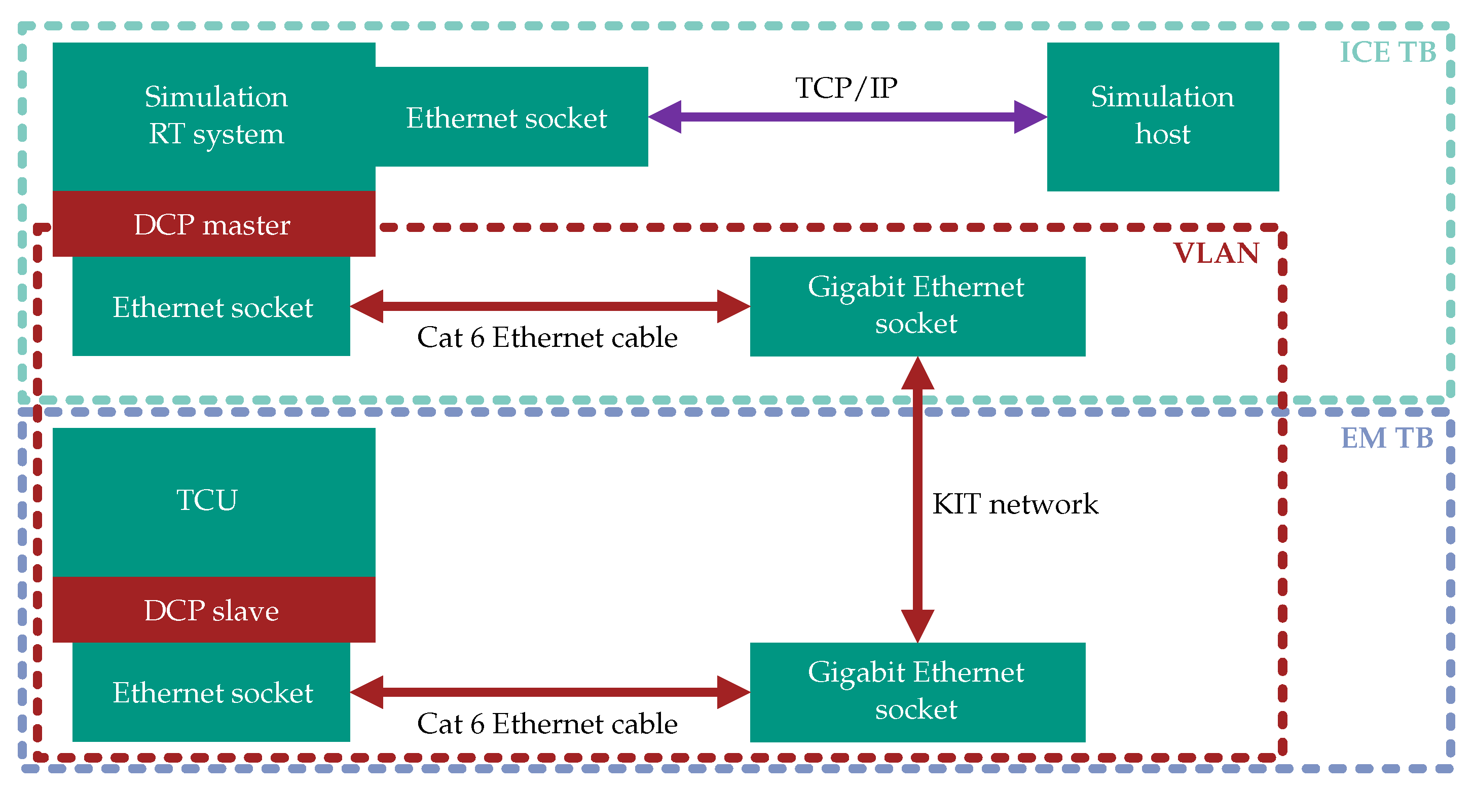
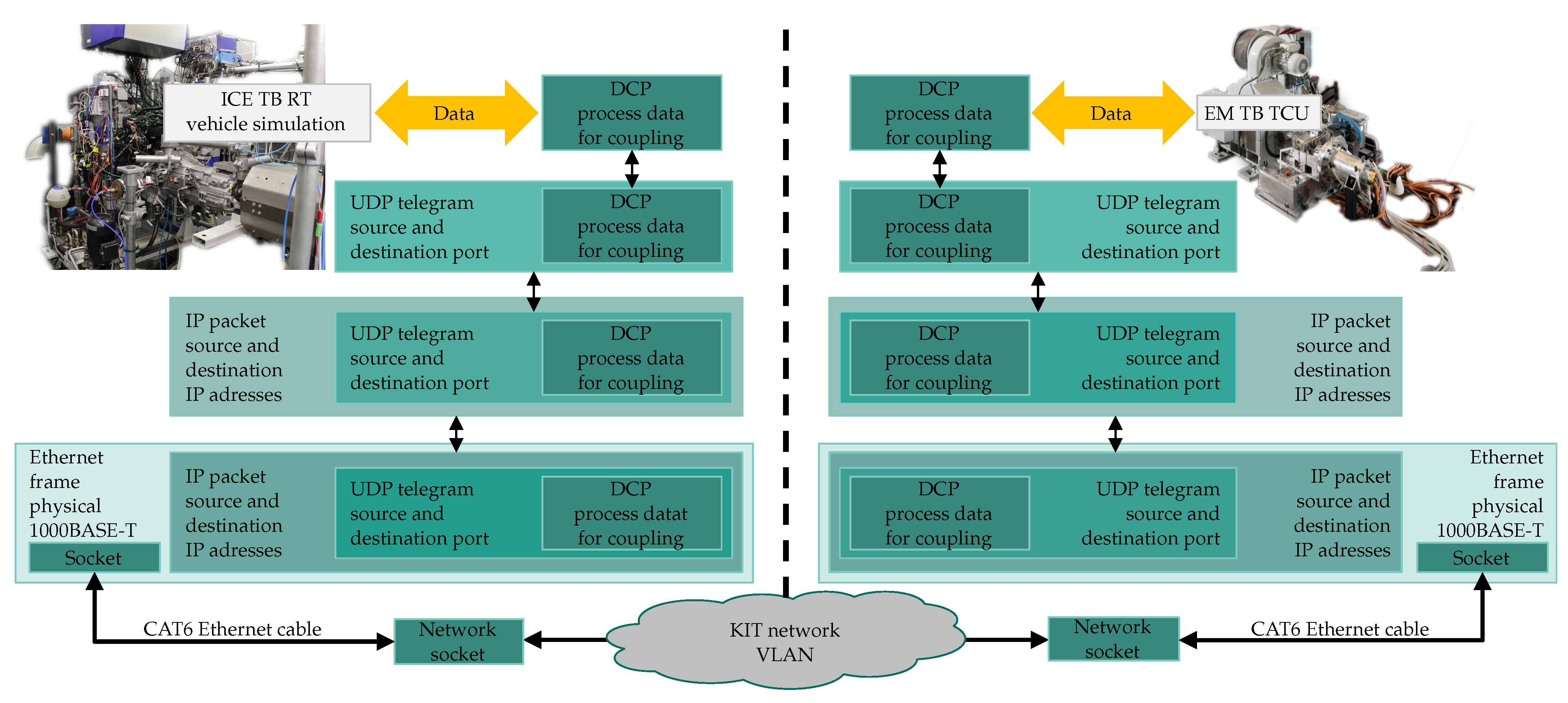
To demonstrate test bench coupling, a communication link between the two test benches needs to be established. For this purpose, the test benches must have a network connection. In the case of the coupling example, a network socket with access to a common VLAN is installed in each case. The coupling and connections used are shown in Figure 4.
For coupling over the Internet, for example, across locations between two different companies, this can be achieved by real-time routers via a VPN tunnel. This variant was tested in the XiL-BW-e project [24].
In addition to the hardware 1000BASE-T Ethernet connection, which concerns the interfaces and cabling for the coupling, the software implementation is subsequently considered in more detail. In general, the data exchange will be handled by the UDP/IP protocol. In contrast to the TCP/IP protocol, the UDP/IP protocol has a higher speed, but has the disadvantage that no native algorithm ensures no package loss during communication. Detailed information and further description can be found in the Refs. [56,57].
Figure 5 shows the communication across the protocols through software and hardware. As shown in the Figure, the data of the test benches required for the coupling are exchanged via the DCP standard. Table 5 and Table 6 list the data exchanged between the two test benches and explain the usage of the data.

3.4. DCP Extension for Hardware Coupling

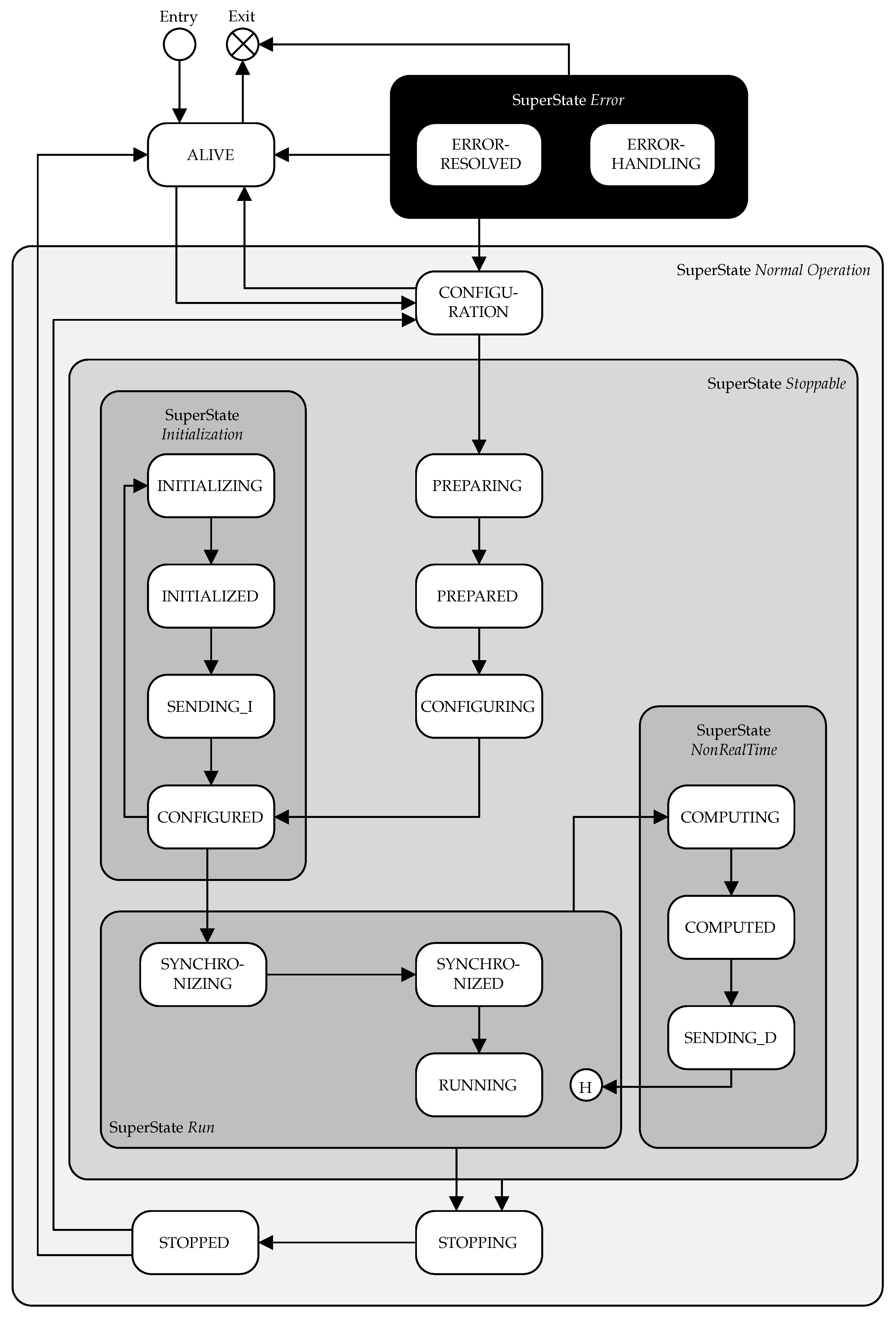
In this Section, the additional functionalities and differences for the DCP implementation for hardware coupling are explained in more detail. In general, the implementation is carried out according to the specification, which provides information about the slave state-machine [10]. The schematic structure of the slave state-machine is shown in Figure 6. A proposal for the master’s state-machine implementation is described in the Ref. [13].

3.4.1. Synchronization and Timing

DCP does not include mechanisms for time synchronization. Regarding synchronization in DCP-coupled test benches, examples from the literature have been given in the Ref. [7], and a recommendation in the DCP specification refers to the Ref. [58]. The challenge within such existing protocol for clock synchronization is the integration in existing systems. Alternatively, the possibility to extend the real-time control unit with the synchronization protocol must be given. For hardware test benches, black box control units are often used. Due to security measures, full access is not granted to the software, and therefore there is no option for additional protocols. Typically, a communication protocol such as UDP/IP or TCP/IP is possible. In this research, synchronization between master and slave was achieved via UDP sequence numbers, added in the data part of a UDP frame. For this purpose, the sequence number is defined and increased in the DCP master with every DCP message to a slave. The slave stores the current number received and sends the number back to the master together with the regular data for coupling. Both the slave and the master check that the sequence numbers are not too far apart (for example, the difference should be <100). The algorithm can be implemented easily and ensures that there is no, or only a small amount of package loss caused using UDP protocol. The sequence number can also be used to check whether the connection was lost, and is therefore an option to detect failures in hardware coupling and switch to the safe state. In the case of the coupled test benches example, the latency of the communication is very low (≤ 3   m s ) due to the spatial proximity of the test benches and the existing VLAN without access via the Internet. If this latency is more significant, as is the case for communication via the Internet, equipping the software, in particular the controls for speed and torque, with predictive behavior is sensible. Using a so-called Smith predictor would be a possibility, as described in the Refs. [59,60].

3.4.2. Safety Concepts

Since the DCP has generally been designed for coupling software and simulation models, there are some preliminary considerations before implementation. For example, giving overall control of the slave to the DCP master is not possible. With the high powers, speeds, and voltages, the test bench must always be prioritized above the coupling application via the DCP for the protection of persons and equipment.
This means that the test benches always guarantee safe operation, and, in case of doubt, the DCP slave ignores the master’s instructions. In the simplest case, the slave does not reach the master’s reference values in the defined test case. In the worst case, this leads to an emergency shutdown of one of the test benches, and thus of the entire test case. If this happens, for example, during a thermal load test that was preceded by time-consuming conditioning, time and resources would be unnecessarily wasted.

3.4.3. Preliminary Considerations and Limit Exchange State

The clarification of the capability of the test benches in advance is important. Forbidden operating points must therefore be identified and recorded as part of the preliminary considerations. These limits depend on the specific test bench hardware.
For example, the speed control of the load machine of the test bench (asynchronous machine) is not fast enough to counter the much faster torque control of the device under test (permanently excited synchronous machine) at very low speeds (approx. 0 to 50min−1) with enough torque to keep the speed at the defined value. In the worst case, oscillations occur in the control of the load machine, which can lead to a shutdown of the test bench.
From the DCP specification, the state CONFIGURATION is defined. In this state, the master has taken control of the slave. At this point, the introduction of a new “Limit Exchange” sub-state has also proved useful. The test benches can exchange their respective limits, such as the maximum possible speed or temperatures, and check whether a test is possible. This prevents errors caused by wrong limits before the test even starts, and saves time due to the avoidance of possibly lengthy thermal component conditioning to a wrong initial temperature. This step can be carried out as a safety state in addition to the indispensable preliminary considerations already described.

3.4.4. Extension of the PREPARING State

According to the DCP specification, after successful configuration, the slave should initiate the transport protocol and thus allow for data exchange. Since the original use of DCP is for coupling software and simulation models, various transport protocols can be used for further communication. In the case of hardware coupling of test benches, however, this flexibility offers no advantage. Hardware coupled test benches require the communication and data exchange to be integrated in the TCU software. However, the availability of various data exchange protocols and the existing test bench systems compatibility cannot be assumed. Additionally, the interfaces are often already required upon start-up of the test bench, meaning that the interfaces are already in use when the DCP master or slave is started. In the case of the coupled test benches example, the state is already fulfilled when specifying its requirements strictly according to DCP. When coupling with a test bench, checking the test bench and components operational availability is advisable. This extends the PREPARING state, or can be implemented by using a “test bench preparation” sub-state. Within this sub-state, a check is performed whether the DUT of the respective test bench is ready and can be operated.
In the case of an ICE, checks are, for example:
  • Fuel pump running and fuel present;
  • Temperature control units switched on and coolant levels OK;
  • Data acquisition devices enabled and ready for operation;
  • No errors in the error memory;
  • Operating mode remote control DCP selected.
With an EM, checks are, for example:
  • Battery emulator running;
  • Temperature control units switched on;
  • Data acquisition devices enabled and ready for operation;
  • No errors in the error memory;
  • Operating mode remote control DCP selected.
In summary, this sub-state checks whether all subsystems within the test bench environment are functioning and prepared for operation. If all aforementioned conditions are fulfilled, this is transferred to the DCP state machine via an internal signal of the TCU.

3.4.5. Extension of DCP CONFIGURING State

When using connectionless communication, as in the case of the coupling example via the UDP protocol, no specific actions are necessary at this point according to the DCP specification. In the case of hardware and test bench coupling, additional functionality is implemented at this point which deviates to the specification. Particularly in the case of thermal tests, very time-consuming thermal conditioning of the test items is sometimes necessary. Another possibility is a primary test bench cool-down to the initial temperature after a high-load test. For this purpose, the sub-state “Test Conditioning” is introduced. In the case of the coupling example, this provides for an exchange of the initial conditions for the desired test case.
The master and slave wait within this state until both test benches are conditioned. The feedback of the slave to the master about a completed conditioning is achieved by comparing the internal measured values of the slave (EM test bench) with the initial conditions received from the master (ICE test bench) for the test case. A constant data exchange during the conditioning does not take place, since such an exchange will take place only during one of the later conditions. Continually sending data to the master during conditioning for recording is possible, depending on the application. If the test benches are conditioned at different speeds, the conditioning of the already finished test bench is kept constant. The exact thermal conditioning process procedure depends on the respective test bench. At the EM test bench, for example, the load machine and the DUT must be in operation for uniform conditioning, and the temperature control medium must flow at low speed. Therefore, the battery emulator must also operate at low voltage. After conditioning is complete, the DCP slave waits in the CONFIGURED state.

3.4.6. Extension of DCP STOPPING State

The test can be terminated by the slave or the master. If only software and simulation models were coupled, this would complete the termination of the test run. In the case of a hardware coupling, however, this must be handled carefully. Thus, after high thermal load, controlled cooling of the load machine as well as the DUT is required. To avoid thermal hot spots in the EM’s windings, this must be performed while the machine continues to rotate. Therefore, the voltage must continue to be applied in the DC link. For this reason, a shutdown procedure and a safe state have been extended as a sub-state for the stop of the DCP, either caused by the normal end of the test or by an error. The shutdown procedure resets the remote control of the TCU in the first step. After that, remote control via the DCP is only possible again after a complete run of the DCP from the ALIVE state. Subsequently, the torque is set to the value 0. The DC link voltage is held at the last value of the test case while the speed is immediately reduced. When the safe state speed is reached ( 100 / min in the test example case), the DUT’s DC link voltage is also reduced.
By first reducing the speed and then the DUT’s DC link voltage, the voltage induced by the DUT never becomes higher than the DC link voltage, which would result in inadmissible current flows in the DUT and inverter. Especially in a fault’s event, this safe state is the first choice for a controlled reduction in the system’s energy. Conditioning of the subsystems can also be carried out at this point, such as by reaching a safe temperature from which further rotation of the DUT can be dispensed with. If all conditions of the safe state are fulfilled, the DCP state machine changes to the STOPPED state where voltage and speed are set to zero.

3.4.7. Superstate ERROR

According to the specification, the superstate ERROR is used to handle exceptions and errors defined by the user. In the case of the test example implementation of the DCP at the EM test bench, every error of the TCU triggers the transition from the superstate NORMALOPERATION to the ERRORHANDLING state. Here, the shutdown procedure is first initiated and the safe state is approached. This is created with a shutdown procedure and a safe state as for the extension in the DCP STOPPING state. Subsequently, the test bench can either be switched off or the error can be corrected and reset in the TCU. Only when there is no more error and the reset is done, the internal signal "resolved" is set and the state ERRORRESOLVED is activated. From here, a new configuration of the test case can be started via a State Change Request (STC) “reset”.

4. Results

4.1. DCP Operation

The functionality of the interacting state machines can be demonstrated in a simulated setup to validate state transitions. In Figure 7, the DCP state IDs for the master and slave are shown, as well as the vehicle velocity, the gas and brake pedal values, and the master’s coolant temperature difference status.
Within the first 100 s , both state machines change their states twice. The slave ID (brown dash-dotted) changes a third time shortly before 100 s . However, the master ID (black dashed) does not change before until ≈ 110 s , when the status for the coolant temperature difference Δ T s t a t u s (green) is set to 0. The master can only leave this state if the slave transmits a CONFIGURED state, and in addition if the master’s conditioning systems are within 1 °C of the desired coolant temperature.
As soon as the master state 5 (RUN) is reached, the test run starts. The virtual driver then releases the brake pedal (blue dash-dotted) and starts controlling the vehicle velocity via the pedals. The control behavior of the virtual driver is not of central importance for the DCP operation, therefore the trend of the gas (orange dashed) and brake pedal (blue dash-dotted) as well as the vehicle velocity (red) will not be discussed further.
A simulated test abort is achieved by setting the master state to 7 (STOP). As a result, the slave also leaves state 11 (RUNNING) and changes to state 15 (STOPPING). The virtual driver sets the gas pedal to zero and applies the brake pedal, resulting in a vehicle standstill. If desired, this transition can be optimized by a suitable communication between state machine and hybrid controller.
For a new test run, the master and slave have to start again at state 0 (REGISTER or ALIVE). A detailed allocation of the state ID and state name is given in Table 7.

4.2. Coupled Operation

The coupled operation is validated by comparing the torques and speeds of the two test benches. An evaluation can be made on the basis of the difference between the reference value specification inputs and the actual measured values. Both the time difference (Equation (1)) and the value difference (Equation (2)) must be considered.
Δ t ( y ) = t 2 ( y ) t 1 ( y ) ,
Δ y ( t ) = y 2 ( t ) y 1 ( t ) .
The reference values are calculated in the simulation, as described in Section 3.1. In the case of the EM, the values must also be sent from the ICE test bench—where the simulation host is located, see Figure 4—to the EM test bench.
For the analysis of the coupled operation, a measurement was performed with the Worldwide harmonized Light-duty vehicles Test Cycle (WLTC) as speed specification. The following parameters were predefined:
  • Start SoC = 20%
  • Start temperature of the EM T E M = 30 °C

4.2.1. Validation of EM

For a better visualization, a dynamic section of the WLTC was selected. In Figure 8, the reference speed n E M , R E F (green) and the actual speed set at the EM test bench n E M , A C T (blue dashed) are shown next to the vehicle velocity v (red). Both the time shift and the value difference are small in this dynamic case. Due to the latency caused by the data transfer required for the virtual coupling, as well as measurement noise or measurement inaccuracies at the test bench, the small deviations can be neglected. The mapping of dynamic speed change demands from the simulation software to the EM due to shifting operations during acceleration or braking is also possible, see speed changes at t 1040 s while increasing vehicle velocity v, although this functionality is typically not used in normal EM test bench operation.
When analyzing the torque in Figure 9, particular attention must be paid to compliance with the maximum dynamic torque of the EM M E M , M A X (red). This is neither exceeded by the reference torque M E M , R E F (green), nor by the torque actually set at the EM test bench M E M , A C T (blue dashed). A value difference between the reference and actual torque is only apparent in the case of torque peaks, but can also be neglected due to measurement noise or measurement inaccuracies at the test bench.

4.2.2. Validation of ICE and Hybrid Controller

The validation of the ICE is closely linked to the validation of the hybrid controller (HC), since the EM is primarily used for torque generation when the SoC is high. As defined in the hybrid controller, the ICE is only used for support at low SoC, for example. For this reason, a start SoC of 20% was chosen to begin in charge sustaining mode.
To validate this purpose, another section of the WLTC was selected (Figure 10). If the pedal position α H C (brown dash-dotted) set by the driver exceeds the limit of the maximum possible throttle position α I C E (green) at the ICE test bench of 50%, the resulting difference is covered by the torque M E M , A C T (blue dashed) set by the EM. If the required pedal position is smaller than the limit value of the ICE, the torque of the EM is zero or negative, depending on the operating mode. For the last case, the reference value for the ICE α I C E is larger than the pedal position α H C set by the driver, because the operation mode load point lifting is executed.

4.3. Discussions

The results from Section 4.1 and Section 4.2 show the successful application of the DCP extension for coupled test bench operation with an ICE and an EM to represent a hybrid electric powertrain. The successfully implemented communication results, above all, in the negligible deviations between reference and actual values for the remote-controlled slave, the EM, as well as the resulting additional EM test bench operations, such as the execution of dynamic gear shift operations.
In addition to the functional test benches and a suitably designed communication, a successful coupling also requires a robust superimposed control unit for distributing the required torques to the combustion engine and the electric motor. This function therefore acts like a superimposed control loop with the aim of realizing the torque desired by the driver in the shortest possible time. To this end, the requested torques are compared with the torques reported back by the combustion engine and electric motor, and readjusted accordingly depending on the situation. In the case of functions with control loops and feedback, attention must be paid to the dead times of the system to be controlled. If the dead times of the whole system exceed a certain value, a stable operation of the superimposed control unit is no longer possible. In this research approach, the high latency in the torque measurement by an external power measuring device is identified as the main cause for the high dead time. As a remedy, the actual torque provided to the hybrid controller was calculated and the measured torque was only used for measurement data recording and validation. This allowed the dead time for measurement to be bypassed and the control loop to remain stable. An integrated measuring device or other measuring systems may enable the use of the measured torque. In the case of torque distribution by the hybrid controller, the dead time can also result from the following parts:
  • Data transmission of the torque reference points from the hybrid controller to the ECU;
  • Adjustment of the currents for the corresponding reference torque;
  • Recording of the measured torque in the engine control unit;
  • Data transmission of the measured torque to the hybrid controller.
The definition of a safe state for each test bench and the monitoring of the communication for connection failures is advisable. Since control of the test benches is handed over to an external master for the duration of the tests, errors may not be detected by the master in time, and unreasonable reference values may be requested in the event of a connection failure. A detailed monitoring strategy is highly recommended, as the probability of a test bench malfunction by an external entity is higher than by an on-site operator. If the test bench detects an error, control must be withdrawn from the master and a safe operating state must be defined. In addition, the master must be informed about the termination of the simulation, so that the test is prematurely terminated. The safe state cannot be defined in general, and depends on the test bench and the periphery.
A conditioning of the components for the coupling of hardware is necessary, especially under thermal preconditions. This procedure also offers the advantage that the test bench reference value limits are derived in a standardized way and can be integrated directly into the software for the test run. In addition, for safety reasons, the limits should also be communicated to the other participants as part of the DCP protocol in order to prevent incorrect reference value requests, and thus, possible undesirable system behavior.
Especially during the setup of the coupled operation and the initial start-up, software access should be as free as possible at the following points:
  • Control units: For the implementation of additional functionalities, such as thermal derating or operation on a variable DC link voltage.
  • DCP implementation: The coupled operation is initially based on the implementation of the DCP standard and the associated coupling via Ethernet, the evaluation of data transfer, and the forwarding of the corresponding setpoints to the test bench components. If a direct implementation is not possible, a gateway can be interposed that takes over the described tasks.
Finally, the extension was only tested on the presented test bench combination, meaning the method’s transferability to other test bench combinations is yet to be proven. Additionally, communication behavior is yet to be tested if the test benches have not been arranged within the same subnetwork. Phenomena occurring due to different company networks as well as several firewalls cannot be estimated.
Further use cases from Figure 1, which were investigated with the presented test setup, are shown in the Refs. [4,5].

5. Conclusions

The authors presented a methodology for the virtual coupling of test benches to represent hybrid electric vehicles by applying and extending the DCP Standard. For this purpose, an overview of related XiL applications and co-simulation scenarios was provided. The EM and ICE test benches used in this research were equipped with UDP/IP communication over a VLAN within the university’s network. In order to be able to guarantee real-time capability and communication reliability, approaches for synchronization and security concepts as well as the balancing of test bench boundary conditions were developed. The test runs performed confirm the DCP extension’s applicability, as demonstrated by the negligible deviations between reference and actual values. Despite the additional latency caused by sending the reference values from the ICE test bench to the EM test bench, the deviation of the speed as well as the torque at the EM test bench are negligible. Stable operation can therefore be guaranteed. Safe shutdown behavior in the event of a failure must nevertheless be ensured.
This once again illustrates the importance of the interaction between test benches and a suitable, higher-level simulation environment for closed-loop operation. The implementation of such a superimposed controller structure must be carried out with particular care, if interventions are to be performed at different points of the test bench network across virtual boundaries. This is caused by higher dead times which can lead to control system instability. The reduction in these dead times at suitable points is the primary remedy. Important lessons also include that the test bench control units and RT systems employed must have open software access, since in many cases, test benches are not prepared for extended test cases, such as with highly dynamic demands. Particularly in a coupled test bench setup, the security measures are of utmost importance to guarantee safe operation, and must therefore be adaptable.
The developed DCP extension for test bench coupling can also be applied to other test bench combinations. The addition of a battery test bench to the test bench setup shown is planned. Usually, battery test benches cannot be physically integrated and can only be tested in spatially separated test bench setups. This enables additional testing possibilities of battery management systems, which can be further extended by testing different ECU architectures in electrified powertrains, as described in the Ref. [61]. This increases test bench utilization in other application areas as well.
The evaluation of the advantages compared to other coupling and test bench applications is still to be performed. For such a comparison, however, criteria must first be defined that allow for an objective evaluation. The same applies to the time advantage within the development process of a powertrain.

Author Contributions

Conceptualization, P.R., P.W., J.P.D. and S.H.; methodology, P.R., P.W., J.P.D. and S.H.; software, P.R., P.W., J.P.D. and S.H.; validation, P.R., P.W., J.P.D. and S.H.; formal analysis, P.R., P.W., J.P.D. and S.H.; investigation, P.R., P.W., J.P.D. and S.H.; resources, P.R., P.W., J.P.D. and S.H.; data curation, P.R., P.W., J.P.D. and S.H.; writing—original draft preparation, P.R., P.W., J.P.D. and S.H.; writing—review and editing, P.R., P.W., J.P.D. and S.H.; visualization, P.R., P.W., J.P.D. and S.H.; supervision, F.G., T.K., M.D. and M.G. All authors have read and agreed to the published version of the manuscript.

Funding

The research project was self-financed (601363) by the FVV (Research Association for Combustion Engines eV).

Institutional Review Board Statement

Not applicable.

Informed Consent Statement

Not applicable.

Data Availability Statement

Not applicable.

Acknowledgments

The authors gratefully acknowledge the support received from the FVV and from all those involved in the project.

Conflicts of Interest

The authors declare no conflict of interest.

Abbreviations

The following abbreviations are used in this manuscript:
ACAlternating current
ACoRTAAdvanced Co-Simulation Methods for Real-Time Applications
ACOSARAdvanced Co-Simulation Open System Architecture
ACTActual
AUTOSARAutomotive Open System Architecture
BEVBattery electric vehicle
CANController Area Network
DCDirect current
DCPDistributed Co-Simulation Protocol
DCPMLDistributed Co-Simulation Protocol Modeling Language
DUTDevice under test
ECUElectronic control unit
EiLEngine-in-the-loop
EMElectric machine
FMIFunctional Mock-up Interface
HCHybrid controller
HEVHybrid electric vehicle
HiLHardware-in-the-loop
HRTHard real-time
HVHigh voltage
ICEInternal combustion engine
IPInternet Protocol
KITKarlsruhe Institute of Technology
MAPModelica Association Project
MiLModel-in-the-loop
NRTNon-real-time
OEMOriginal equipment manufacturer
OSIOpen Systems Interconnection
ProMECoSProcess model for efficient Distributed Co-Simulation
RDEReal Driving Emissions
REFReference
RTReal-time
SiLSoftware-in-the-loop
SoCState-of-charge
SRTSoft real-time
STCState Change Request
TBTest bench
TCPTransmission Control Protocol
TCUTest bench control unit
UDPUser Datagram Protocol
ViLVehicle-in-the-loop
VLANVirtual Local Area Network
VPNVirtual Private Network
WLTCWorldwide harmonized Light-duty vehicles Test Cycle
WLTPWorldwide harmonized Light-duty vehicles Test Procedure
XiLX-in-the-Loop

References

  1. European Commission. Communication from the Commission to the European Parliament, the European Council, the Council, the European Economic and Social Committee and the Committee of the Regions: The European Green Deal. 2019. Available online: https://eur-lex.europa.eu/resource.html?uri=cellar:b828d165-1c22-11ea-8c1f-01aa75ed71a1.0002.02/DOC_1&format=PDF (accessed on 10 January 2023).
  2. Cubito, C.; Millo, F.; Boccardo, G.; Di Pierro, G.; Ciuffo, B.; Fontaras, G.; Serra, S.; Otura Garcia, M.; Trentadue, G. Impact of Different Driving Cycles and Operating Conditions on CO2 Emissions and Energy Management Strategies of a Euro-6 Hybrid Electric Vehicle. Energies 2017, 10, 1590. [Google Scholar] [CrossRef]
  3. De Santis, M.; Silvestri, L.; Forcina, A. Promoting electric vehicle demand in Europe: Design of innovative electricity consumption simulator and subsidy strategies based on well-to-wheel analysis. Energy Convers. Manag. 2022, 270, 116279. [Google Scholar] [CrossRef]
  4. Rautenberg, P.; Degel, J.P.; Hähnlein, S.; Weber, P. Thermische Tests im gekoppelten Prüfstandsbetrieb. MTZextra 2021, 26, 36–39. [Google Scholar] [CrossRef]
  5. Weber, P.; Hähnlein, S.; Rautenberg, P.; Gohl, M. Potentials of Coupled Test Benches. MTZ Worldw. 2022, 83, 66–70. [Google Scholar] [CrossRef]
  6. VDI/VDE Society Measurement and Automation. Development of Mechatronic and Cyber-Physical Systems. Verein Deutscher Ingenieure e.V., VDI/VDE 2206. 2021. Available online: https://engrxiv.org/preprint/view/2452/4716 (accessed on 10 January 2023).
  7. Krammer, M.; Ferner, P.; Watzenig, D. Clock Synchronization in Context of the Distributed Co-Simulation Protocol. In Proceedings of the 2019 IEEE International Conference on Connected Vehicles and Expo (ICCVE), Graz, Austria, 4–8 November 2019; pp. 1–6. [Google Scholar] [CrossRef]
  8. Blochwitz, T.; König, C.; Mikelsons, L.; Ewald, S.; Beringer, S.; Nagarajan, N.; Fu, D.; Haid, T.; Baumann, M.; Schreiber, V. Advanced Co-Simulation Open System Architecture: ACOSAR-Abschlussbericht: Gemeinsamer Abschlussbericht: Förderzeitraum: 01.09.2015-31.08.2018; Robert Bosch GmbH: Renningen, Germany, 2019. [Google Scholar] [CrossRef]
  9. Lichtenstein, L.; Ries, F.; Völker, M.; Höll, J.; König, C.; Zehetner, J.; Kotte, O.; Coral, I.; Mikelsons, L.; Amringer, N.; et al. Literature Review in the Fields of Standards, Projects, Industry and Science. 2016. Available online: https://itea4.org/project/workpackage/document/download/3198/D1.1.%20ACOSAR%20-%20Literature%20Review.pdf (accessed on 10 January 2023).
  10. Modelica Association Project DCP. DCP Specification Document: Version 1.0. 2019. Available online: https://dcp-standard.org/assets/specification/DCP_Specification_v1.0.pdf (accessed on 10 January 2023).
  11. Krammer, M.; Benedikt, M. Configuration of Slaves Based on the Distributed Co-Simulation Protocol. In Proceedings of the 2018 IEEE 23rd International Conference on Emerging Technologies and Factory Automation (ETFA), Turin, Italy, 4–7 September 2018; IEEE: Piscataway, NJ, USA, 2018; pp. 195–202. [Google Scholar] [CrossRef]
  12. Krammer, M.; Benedikt, M.; Blochwitz, T.; Alekeish, K.; Amringer, N.; Kater, C.; Materne, S.; Ruvalcaba, R.; Schuch, K.; Zehetner, J.; et al. The Distributed Co-Simulation Protocol for the Integration of Real-Time Systems and Simulation Environments. In Proceedings of the 50th Computer Simulation Conference, Bordeaux, France, 9–12 July 2018. [Google Scholar] [CrossRef]
  13. Krammer, M.; Benedikt, M. Master for Simulation Control using the Distributed Co-Simulation Protocol. In Proceedings of the IEEE 16th International Conference on Industrial Informatics (INDIN), Porto, Portugal, 18–20 July 2018; IEEE: Piscataway, NJ, USA, 2018; pp. 329–334. [Google Scholar] [CrossRef]
  14. Krammer, M.; Kater, C.; Schiffer, C.; Benedikt, M. A Protocol-Based Verification Approach for Standard-Compliant Distributed Co-Simulation. In Proceedings of the Asian Modelica Conference, Tokyo, Japan, 8–9 October 2020. [Google Scholar] [CrossRef]
  15. Krammer, M.; Marko, N.; Benedikt, M. Requirements Engineering for Consensus-Oriented Technical Specifications. In Proceedings of the 2018 IEEE 26th International Requirements Engineering Conference (RE), Banff, AB, Canada, 20–24 August 2018; pp. 315–324. [Google Scholar] [CrossRef]
  16. Krammer, M.; Benedikt, M. Design and Application of a Domain Specific Modeling Language for Distributed Co-Simulation. In Proceedings of the 2019 IEEE 17th International Conference on Industrial Informatics (INDIN), Helsinki, Finland, 22–25 July 2019; pp. 677–682. [Google Scholar] [CrossRef]
  17. Krammer, M.; Schiffer, C.; Benedikt, M. ProMECoS: A Process Model for Efficient Standard-Driven Distributed Co-Simulation. Electronics 2021, 10, 633. [Google Scholar] [CrossRef]
  18. Stettinger, G.; Horn, M.; Benedikt, M.; Zehetner, J. Model-based coupling approach for non-iterative real-time co-simulation. In Proceedings of the 2014 European Control Conference (ECC 2014), Strasbourg, France, 24–27 June 2014; pp. 2084–2089. [Google Scholar] [CrossRef]
  19. Stettinger, G.; Benedikt, M.; Tranninger, M.; Horn, M.; Zehetner, J. Recursive FIR-Filter design for fault-tolerant real-time co-simulation. In Proceedings of the 2017 25th Mediterranean Conference on Control and Automation (MED), Valletta, Malta, 3–6 July 2017; pp. 461–466. [Google Scholar] [CrossRef]
  20. Tranninger, M.; Haid, T.; Stettinger, G.; Benedikt, M.; Horn, M. Fault-tolerant coupling of real-time systems: A case study. In Proceedings of the 2016 3rd Conference on Control and Fault-Tolerant Systems (SysTol), Barcelona, Spain, 7–9 September 2016; pp. 756–762. [Google Scholar] [CrossRef]
  21. Stettinger, G.; Zehetner, J.; Benedikt, M.; Thek, N. Extending Co-Simulation to the Real-Time Domain; SAE Technical Paper Series; SAE International: Warrendale, PA, USA, 2013. [Google Scholar] [CrossRef]
  22. Zehetner, J.; Benedikt, M.; Wierse, M.; Kokal, H.; Paulweber, M.; Stettinger, G.; Toye, B. Control of an engine test-bench via hardware-software-co-simulation. In 14. Internationales Stuttgarter Symposium; Proceedings; Bargende, M., Reuss, H.C., Wiedemann, J., Eds.; Springer Fachmedien Wiesbaden: Wiesbaden, Germany, 2014; pp. 1675–1686. [Google Scholar] [CrossRef]
  23. Zehetner, J.; Stettinger, G.; Kokal, H.; Toye, B. Echtzeit-Co-Simulation für die Regelung eines Motorprüfstands. ATZ-Automob. Z. 2014, 116, 40–45. [Google Scholar] [CrossRef]
  24. Albers, A.; Dietmayer, K.; Bargende, M.; Behrendt, M.; Yan, S.; Buchholz, M.; Bernthaler, T. XiL-BW-e–Laboratory Network Baden-Württemberg for Electric Mobility. In Proceedings of the 30th International Electric Vehicle Symposium & Exhibition, Stuttgart, Germany, 9–11 October 2017; Volume 11. [Google Scholar]
  25. Matitschka, J.; Berger, J.; Ott, S. Anforderungen an den mechanischen Aufbau und die Messtechnik beim Test von Antriebskomponenten in einer Echtzeitumgebung. In Proceedings of the 9. VDI-Fachtagung Schwingungen in Antrieben, Fulda, Germany, 28–29 October 2015; Volume 2262. [Google Scholar]
  26. Albers, A.; Yan, S.; Behrendt, M. Validation Support for Distributed Vehicle Development Based on the XiL-Approach. In Proceedings of the FISITA 2016 World Automotive Congress, BEXCO, Busan, Republic of Korea, 26–30 September 2016. [Google Scholar]
  27. You, Y. Eine Studie zur Implementierung des IPEK-X-in-the-Loop-Ansatzes in der Verteilten Fahrzeugentwicklung am Beispiel Antriebsstrangentwicklung; Forschungsberichte; IPEK, KIT Scientific Publishing: Karlsruhe, Germany, 2018. [Google Scholar] [CrossRef]
  28. Yan, S.L. Vernetzte Validierungsumgebungen—Ein Beitrag zur Validierung im Verteilten Produktentwicklungsumfeld auf Basis des IPEK-X-in-the-Loop-Ansatzes am Beispiel der Antriebssystementwicklung; Forschungsberichte; IPEK, KIT Scientific Publishing: Karlsruhe, Germany, 2020; Available online: https://publikationen.bibliothek.kit.edu/1000126974 (accessed on 10 January 2023)Forschungsberichte.
  29. Wäschle, M.; Wolter, K.; Han, C.; Pecha, U.; Bause, K.; Behrendt, M. Validation concept for scenario-based connected test benches of a highly automated vehicle. In Automatisiertes Fahren 2021; Bertram, T., Ed.; Proceedings; Springer Fachmedien Wiesbaden: Wiesbaden, Germany, 2021; pp. 95–109. [Google Scholar] [CrossRef]
  30. Nickel, D.; Stelter, E.; Sültrop, C.; Mittmann, W.; Heiduczek, T.; Hohenner, H. Innovative Testing Process for Electric Powertrains. In Proceedings of the EVS30 International Battery, Hybrid and Fuel Cell Electric Vehicle Symposium, Stuttgart, Germany, 9–11 October 2017. [Google Scholar]
  31. Schyr, C.; Stelter, E.; Sültrop, C.; Wild, C.; Heiduczek, T. Connected Testing of Electric Powertrains. In Proceedings of the 7th International Symposium on Development Methodology, Wiesbaden, Germany, 14–15 November 2017. [Google Scholar]
  32. Nickel, D.; Behrendt, M.; Bause, K.; Albers, A. Connected testbeds—Early validation in a distributed development environment. In 18. Internationales Stuttgarter Symposium; Proceedings; Springer Fachmedien Wiesbaden: Wiesbaden, Germany, 2018; pp. 1173–1185. [Google Scholar] [CrossRef]
  33. Nickel, D.; Stelter, E.; Mittmann, W.; Heiduczek, T. Vernetzte Test-und Simulationsumgebungen. MTZextra 2018, 23, 18–23. [Google Scholar] [CrossRef]
  34. Andert, J.; Huth, T.; Savelsberg, R.; Politsch, D. Testen von Antriebssträngen mit der virtuellen Welle. MTZextra 2015, 20, 30–35. [Google Scholar] [CrossRef]
  35. Andert, J.; Klein, S.; Savelsberg, R.; Pischinger, S.; Hameyer, K. Virtual shaft: Synchronized motion control for real time testing of automotive powertrains. Control Eng. Pract. 2016, 56, 101–110. [Google Scholar] [CrossRef]
  36. Andert, J.; Savelsberg, R.; Klein, S. Verfahren zum Betreiben einer Prüfanordnung, Simulationseinheit zum Simulieren einer Mechanischen Welle und Prüfanordnung. Germany Patent DE102016124753A1, 19 December 2016. [Google Scholar]
  37. Xia, F.; Lee, S.Y.; Andert, J.; Kampmeier, A.; Scheel, T.; Ehrly lng, M.; Tharmakulasingam, R.; Takahashi, Y.; Kumagai, T. Crank-Angle Resolved Real-Time Engine Modelling: A Seamless Transfer from Concept Design to HiL Testing. SAE Int. J. Engines 2018, 11, 1385–1398. [Google Scholar] [CrossRef]
  38. Xia, F. Real-Time Capable One-Dimensional Models for Internal Combustion Engines in X-in-the-Loop Applications; RWTH Aachen University: Aachen, Germany, 2020. [Google Scholar] [CrossRef]
  39. Lee, S.Y.; Andert, J.; Quérel, C.; Schaub, J.; Kötter, M.; Politsch, D.; Hadj-amor, H. X-in-the-Loop-basierte Kalibrierung: HiL Simulation eines virtuellen Dieselantriebsstrangs. In Simulation und Test 2017; Liebl, J., Beidl, C., Eds.; Proceedings; Springer Vieweg: Wiesbaden, Germany, 2018; pp. 53–79. [Google Scholar] [CrossRef]
  40. Guse, D.; Andert, J.; Walter, S.; Meyer, N. Next Level of Testing - Erweitertes Frontloading durch latenzoptimerte EiL-Prüfstände. MTZ-Mot. Z. 2020, 81, 42–49. [Google Scholar] [CrossRef]
  41. Klein, S.; Savelsberg, R.; Xia, F.; Guse, D.; Andert, J.; Blochwitz, T.; Bellanger, C.; Walter, S.; Beringer, S.; Jochheim, J.; et al. Engine in the Loop: Closed Loop Test Bench Control with Real-Time Simulation. SAE Int. J. Commer. Veh. 2017, 10, 95–106. [Google Scholar] [CrossRef]
  42. Klein, S.; Griefnow, P.; Guse, D.; Xia, F.; Andert, J. Virtual 48 V Mild Hybridization: Efficient Validation by Engine-in-the-Loop. SAE Int. J. Altern. Powertrains 2018, 7, 297–309. [Google Scholar] [CrossRef]
  43. Klein, S.; Xia, F.; Etzold, K.; Andert, J.; Amringer, N.; Walter, S.; Blochwitz, T.; Bellanger, C. Electric-Motor-in-the-Loop: Efficient Testing and Calibration of Hybrid Power Trains. IFAC-PapersOnLine 2018, 51, 240–245. [Google Scholar] [CrossRef]
  44. Walter, S.; Guse, D.; Klein, S.; Meyer, N.; Andert, J.; Schulze, T. Engine-in-the-Loop—Auswirkung der Echtzeitperformance auf die Abbildungsgüte von Fahrzyklen. In Experten-Forum Powertrain: Simulation und Test 2019; Liebl, J., Ed.; Proceedings; Springer Vieweg: Wiesbaden, Germany, 2020; pp. 153–171. [Google Scholar] [CrossRef]
  45. Klein, S. Motor test Bench as Embedded System within a Vehicle Simulation; RWTH Aachen University: Aachen, Germany, 2020. [Google Scholar] [CrossRef]
  46. Eisenbarth, M.; Etzold, K.; Andert, J.; Plum, T.; Reinold, P.; Schwarz, U.; Gries, R. A Holistic Methodology for the Development of Connected Hybrid Vehicles. In Proceedings of the 7th International Symposium on Development Methodology, Wiesbaden, Germany, 14–15 November 2017. [Google Scholar]
  47. Reinold, P.; Meyer, N.; Buse, D.; Klingler, F.; Sommer, C.; Dressler, F.; Eisenbarth, M.; Andert, J. Verkehrssimulation im Hardware-in-the-Loop-Steuergerätetest. In Simulation und Test 2018; Liebl, J., Ed.; Springer Vieweg: Wiesbaden, Germany, 2019; pp. 253–269. [Google Scholar] [CrossRef]
  48. Etzold, K.; Fahrbach, T.; Herold, K.; Andert, J. Thermische Hardware-in-the-Loop-Tests von elektrischen Traktionsmaschinen. ATZ-Automob. Z. 2019, 121, 54–59. [Google Scholar] [CrossRef]
  49. Granrath, C.; Meyer, M.A.; Andert, J.; Richenhagen, J. Methodik zur Entwicklung einer standardisierten virtuellen Validierungsumgebung für Elektrofahrzeuge. In Antriebstechnisches Kolloquium 2019; Jacobs, G., Marheineke, J., Eds.; Books on Demand: Norderstedt, Germany, 2019. [Google Scholar] [CrossRef]
  50. Lenz, M.; Etzold, K.; Klein, S.; Hüske, M. Virtuelle Hochvoltbatteriesysteme: Closed Loop Testing bei vorverlagerten Entwicklungsprozessen. In Simulation und Test 2018; Liebl, J., Ed.; Springer Vieweg: Wiesbaden, Germany, 2019; pp. 147–168. [Google Scholar] [CrossRef]
  51. Rautenberg, P.; Kurz, C.; Gießler, M.; Gauterin, F. Driving Robot for Reproducible Testing: A Novel Combination of Pedal and Steering Robot on a Steerable Vehicle Test Bench. Vehicles 2022, 4, 727–743. [Google Scholar] [CrossRef]
  52. Gesner, P.; Jakobi, R.; Klein, P.; Horstkötter, I.; Bäker, B. Data-Enhanced Battery Simulator for Testing Electric Powertrains. In 21. Internationales Stuttgarter Symposium; Springer Vieweg: Wiesbaden, Germany, 2021; pp. 177–191. [Google Scholar] [CrossRef]
  53. Doppelbauer, M. Grundlagen der Elektromobilität; Springer: Berlin/Heidelberg, Germany, 2020. [Google Scholar] [CrossRef]
  54. Hu, D.; Xu, L. Characterizing the torque lookup table of an IPM machine for automotive application. In Proceedings of the 2014 IEEE Conference and Expo Transportation Electrification Asia-Pacific (ITEC Asia-Pacific), Beijing, China, 31 August–3 September 2014; pp. 1–6. [Google Scholar] [CrossRef]
  55. Richter, J. Modellbildung, Parameteridentifikation und Regelung hoch ausgenutzter Synchronmaschinen; KIT Scientific Publishing: Karlsruhe, Germany, 2016; p. 178. [Google Scholar] [CrossRef]
  56. Häckelmann, H.; Petzold, H.J.; Strahringer, S. Kommunikationssysteme; Springer: Berlin/Heidelberg, Germany, 2000. [Google Scholar] [CrossRef]
  57. Mandl, P. Grundkurs Datenkommunikation, 2nd ed.; SpringerLink Bücher, Vieweg+Teubner: Wiesbaden, Germany, 2010. [Google Scholar] [CrossRef]
  58. Eidson, J.C.; Fischer, M.; White, J. IEEE-1588-2002; Standard for a Precision Clock Synchronization Protocol for Networked Measurement and Control Systems. Naval Research Lab: Washington, DC, USA, 2002; pp. 243–254.
  59. Sanz, R.; García, P.; Albertos, P. A generalized smith predictor for unstable time-delay SISO systems. ISA Trans. 2018, 72, 197–204. [Google Scholar] [CrossRef] [Green Version]
  60. Nicola, M.; Nicola, C.I.; Duţă, M. Delay Compensation in the PMSM Control by using a Smith Predictor. In Proceedings of the 2019 8th International Conference on Modern Power Systems (MPS), Cluj, Romania, 21–23 May 2019; pp. 1–6. [Google Scholar] [CrossRef]
  61. Schärtel, L.; Reick, B.; Pfeil, M.; Stetter, R. Analysis and Synthesis of Architectures for Automotive Battery Management Systems. Appl. Sci. 2022, 12, 10756. [Google Scholar] [CrossRef]
Figure 1. Visualization of test cases in vehicle development as a function of time, effort, and required system development [5].
Applsci 13 02657 g001
Figure 2. Schematic setup of the EM test bench.
Applsci 13 02657 g002
Figure 3. Schematic setup of the ICE test bench.
Applsci 13 02657 g003
Figure 4. Network setup for test bench coupling [4].
Applsci 13 02657 g004
Figure 5. Communication protocol stack utilized in this research.
Applsci 13 02657 g005
Figure 6. Standard DCP slave state machine implementation, based on the Ref. [10].
Applsci 13 02657 g006
Figure 7. Example of DCP state machine functionality.
Applsci 13 02657 g007
Figure 8. Reference n E M , R E F and actual speed n E M , A C T of the EM in a WLTC compared to the virtual vehicle velocity v A C T .
Applsci 13 02657 g008
Figure 9. Reference M E M , R E F and actual torque M E M , A C T of the EM in a WLTC compared to the maximum permitted torque M E M , M A X .
Applsci 13 02657 g009
Figure 10. Accelerator pedal α H C and throttle valve position α I C E in a WLTC compared to the actual torque of the EM M E M , A C T .
Applsci 13 02657 g010
Table 1. Categorization of a literature selection on test bench coupling projects and approaches.
NameLiteratureResearch Focus
ACoRTA[18,19,20,21,22,23]RT co-simulation
Satisfying HRT conditions
XiL-BW-e[24,25,26,27,28]Regional network for XiL approaches
Distributed delevopment and connected validation
SmartLoad[29]Validation concept for highly automated vehicle
Implementation of DCP standard called ‘DCPLite’
TechReaL[30,31,32,33]Technology readiness level raise of BEVs
Early realistic testing through connected test benches
Virtual shaft[34,35,36,37,38,39,40,41,42,43,44,45]Network setup between different test benches
RT performance on driving cycle reproducibility
Hy-Nets[46,47]Connected and automated HEVs
Traffic simulation in ECU testing
HIFI-ELEMENTS[48,49]Validation environment standards for BEV
Thermal HiL tests
DUETT[50]Combined physical–virtual environments
Closed-loop approach for virtual HV battery systems
Table 2. EM test bench system parameters.
ComponentParameterValue
Active front-end and battery simulatorMax. DC voltage 900 V
Max. DCDC current 900 A
Max. power 250 k W
AC inverterMax. DC voltage 800 V
Rms AC current 500 A
Max. power 250 k W
Load machineMax. power 215 k W
Max. speed15,000 min−1
Max. torque 540 N m
Device under testPeak power 85 k W
Continuous power 40 k W
Max. speed6500 min−1
Table 3. Power data of the EM temperature conditioning system.
ParameterValue
Heating capacity temperature control units 9 k W
Cooling capacity at 90 °C medium temperature
and 20 °C domestic cooling water flow
90 k W
Heating time of the test specimen25 °C to 80 °C in 9 min
Cooling time of the test specimen high temperature80 °C to 50 °C in 7 min
Cooling time of the test specimen low temperature50 °C to 35 °C in 23 min
Table 4. ICE test bench system parameters.
ComponentParameterValue
Load machineMax. torque 1400 N m
Max. speed8000 min−1
Max. mech. power 330 k W
Device under testMax. power 225 k W @ 5800 min−1
Max. torque 400 N m @ 1200–5000 min−1
Table 5. Data sent from the ICE test bench (master) to the EM test bench (slave).
ParameterExplanation
DCP master IDIntegration of DCP protocol
UDP sequence numberFor synchronization and communication check
UDP message typeAddition for messages like limit exchange
Reference torqueReference value for EM torque
Reference speedReference value for test bench speed
Reference DC link voltageReference value for battery simulator
Reference oil temperatureReference value for DUT temperature conditioning
Table 6. Data sent from the EM test bench (slave) to the ICE test bench (master).
ParameterExplanation
DCP slave IDIntegration of DCP protocol
UDP sequence numberFor synchronization and communication check
UDP message typeAddition for messages such as limit exchange
Measured DC link voltageFor control and data acquisition
Measured torqueFor control and data acquisition
Maximum torqueFor control, derating, and data acquisition
DUT max. temperatureFor control and data acquisition
DUT mean temperatureFor control and data acquisition
DC, AC and mechanical PowerFor control and data acquisition
DUT max. powerFor control, derating, and data acquisition
Oil temperature (inlet, outlet)For control and data acquisition
DC currentFor control, derating, and data acquisition
Table 7. DCP state IDs and related states for master and slave.
State IDMaster StateSlave State
0REGISTERALIVE
1CONFIGURECONFIGURATION
2APPLYPREPARING
3INITIALIZEPREPARED
4SEND_ICONFIGURING
5RUNCONFIGURED
6SEND_DINITIALIZING
7STOPINITIALIZED
8STOPPEDSENDING_I
9 SYNCHRONIZING
10 SYNCHRONIZED
11 RUNNING
12 COMPUTING
13 COMPUTED
14 SENDING_D
15 STOPPING
16 STOPPED
17 ERRORHANDLING
18 ERRORRESOLVED
Disclaimer/Publisher’s Note: The statements, opinions and data contained in all publications are solely those of the individual author(s) and contributor(s) and not of MDPI and/or the editor(s). MDPI and/or the editor(s) disclaim responsibility for any injury to people or property resulting from any ideas, methods, instructions or products referred to in the content.

