Article

Vitreosity as a Major Grain Quality Indicator—Upgrading the Grain-Cutter Method with a New Blade

by
Krešimir Mastanjević
1,*,
Kristina Habschied
1,
Krešimir Dvojković
2,
Mirko Karakašić
3 and
Hrvoje Glavaš
4
1
Faculty of Food Technology, Josip Juraj Strossmayer University of Osijek, 31000 Osijek, Croatia
2
Agricultural Institute Osijek, Južno Predgrađe 17, 31000 Osijek, Croatia
3
Mechanical Engineering Faculty, University of Slavonski Brod, Trg Ivane Brlić-Mažuranić 2, 35000 Slavonski Brod, Croatia
4
Faculty of Electrical Engineering, Computer Science and Information Technology, Josip Juraj Strossmayer University of Osijek, Kneza Trpimira 2b, 31000 Osijek, Croatia
*
Author to whom correspondence should be addressed.
Appl. Sci. 2023, 13(4), 2655; https://doi.org/10.3390/app13042655
Submission received: 30 January 2023 / Revised: 12 February 2023 / Accepted: 16 February 2023 / Published: 18 February 2023

Abstract

:

Featured Application

The implemented novel solution gives a better insight in grain vitreosity due to a clearer cut which results in cleaner pictures that are easier to read. Also, lower force is needed to conduct the cut.

Abstract

One of the main quality characteristics of cereals, especially wheat is its hardness which is closely related with grain’s vitreosity, one of the main quality indicators of a variety. Determination of vitreosity is usually done visually: namely, after the grain is cut with a commercially available grain-cutters, the cut can result in broken or crushed grains which disables the reading and hinders the precision and accuracy. Also, the moment produced from the manual force on the grain-cutter crank, needed to cut the sample of cca. 50 grains placed in the cutter is an average of 30 Nm. Due to the resistance of the grain, yank force appears. This force can cause the whole instrument to be displaced during cutting. To minimize the errors using a commercially available cutter, a new knife/blade has been implemented and tested. The blade of the new knife is turned at the inclination angle of 49° in relation to the cutting objects (grains). This design solution enables achievement of the grain “cutting”, not grain “tearing”, as observed with the existing commercial design solution. With the proposed new design solution, amount of the moment is reduced to 2.72 Nm and the yank force is completely avoided. Also, a significantly lower amount of the cutting force, on the knife blade is achieved. The results obtained with the new knife gave a better read, were more precise, and the gadget was easier to operate since it demanded lower force to cut the grains. The novelty introduced by this research provided better and more reliable insight into determining the vitreousness of grains. Providing a clearer cut and better readability, this solution goes beyond the current literature by reducing the force required for analysis and speeding up the analysis process.

1. Introduction

Hardness of wheat’s endosperm is the key indicator of wheat quality when it comes to determining its suitability for different end products and affects further processing and milling stages. This is why hardness is the common indicator used by the milling industry. Another quality indicator that narrowly correlates with hardness, total share and structure of proteins is vitreosity. Vitreosity is used as an important indicator of grains’ technological suitability for further industrial processing [1,2]. This is a physical-chemical, optical property of wheat’s endosperm, rather its texture. According to Dexter et al. [3,4], vitreosity is the glassy and translucent appearance of durum wheat kernels caused by a tightly packed endosperm structure with no air spaces in the protein matrix. Although vitreosity is firstly a variety-related property, conditioned by genetics, the degree of vitreosity is partly affected by the agrotechnical measures and weather conditions during vegetation [5,6]. Vitreous grains are commonly hard and have a natural opacity (vitreosity); they also have a higher protein share (glutenin and gliadin) in comparison to starchy part of the endosperm [1,7]; and they have a higher density that is manifested as increased hardness and is exhibited as a resistance toward mechanical shearing during milling [4,8]. Grain classification based on hardness or vitreosity is very similar [9]. According to hardness, wheats are generally divided to hard and soft varieties [5]. Recently, an updated classification included several classes of hardness since many of the European cultivars and varieties that make up the biggest share at the market are actually a transition between soft and hard. They are prone to convert, that is that they formally have the designated hardness, but when subjected to industrial processing they act like soft wheats. This is called a fake or transient vitreosity, a vitreosity that is lost after the grain has been soaked in water. Thus, most authors consider a variety as hard if it has ˃85% of vitreous grains [10]. Based on vitreosity, wheat can be classified into three main classes: vitreous, mealy and partly vitreous. Vitreous wheat is different from mealy wheat by the look of the endosperm (starchy and non-transparent starch granules). It is considered to be of better quality than the mealy varieties due to the more quality grits proteins, yellowish grits color and more even coarse granulation [11]. Wheat vitreosity is a quality property that can be, as opposed to hardness, protein share and structure, visually determined. Today’s non-invasive techniques for vitreosity determination include X-ray, Transmitted light image analysis, VIS/NIR spectroscopy. However, all these methods ask for sophisticated equipment, that is hard to relocate and requires large series of samples to be profitable. This is why this property is commonly determined using a visual ICC Method Standard 129, that relies on Pohl’s grain cutter measurement technique [12,13]. This is a destructive method (cutting the grain), but it does not require expensive equipment or educated/specialized personnel and is representable for a small number of samples. Today, this method can be coupled with digital image analysis (DIA) which results in error rate reduction due the reduction of analyst’s subjectivity. However, grains differ in size (large, medium, small, deficient), hardness (very hard, medium hard, mealy, extremely mealy), and shape (oval, elongated, irregular). These differences are a result of variations in physical-chemical content of grains due to the variety (genetics) or extrinsic influences during vegetation period (draught, pathogens, etc.). To do a valid visual inspection of the grain, the cut must be clean and clear (Figure 1).
Commercial knife construction (Figure 2) is not well suited for its purpose, and the cut often breaks or crushes (Figure 3) the grains duet he the above-mentioned deformations in grains’ size, shape or hardness.
The reason these malformations in cutting appear is because the two boards are actually taring on one another and thus the analyst has to apply great force (yank) to cut the grain. Following problems appear when using a commercially available cutter:
(1)
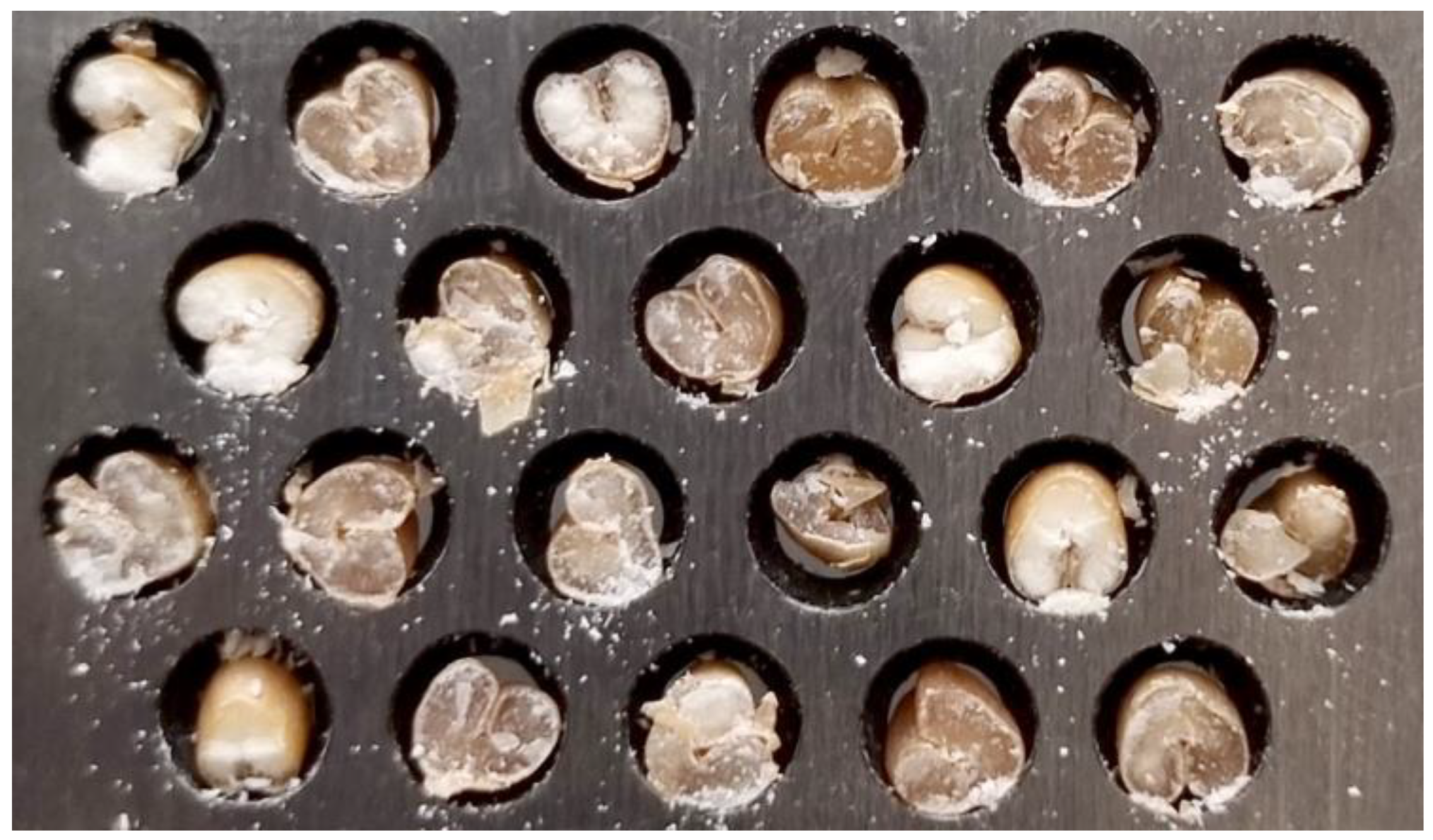
the yank has to be very forceful when analyzing vitreous wheat and thus a certain number of grains fall out of the wells on the cutting board. A certain number of irregularly shaped grains get crushed or broken which results in destroyed grain surface from which it is very hard to visually read the share of vitreous or mealy area. This particularly affects the DIA.
(2)
since great force is needed to cut the grains, very often the whole instrument gets twisted or moved due the moment of force. Placing it to its place requires additional time which prolongs the analysis.
This is particularly expressed in grains of mixed texture (in which the hard and soft parts of the endosperm are both present) that contributes different resistance to sheering which leads to breaking and crushing of the endosperm. This affects the reliability of the method, as mentioned before. Thus, an upgraded solution of the knife is needed to provide a better and clearer cut.
In the attempt to address and possibly solve such troubleshooting, this paper describes an upgraded construction of grain cutter. In order to improve the standard method for vitreosity determination, the construction of this knife could minimize the mentioned negative effects of the old cutter (knife), speed up the analysis time and provide less employment of the analyst during analysis. The basic hypothesis of the paper is that better cutting will lead to a reduction in the deviation of the value for the evaluation of vitrification, which is the first step toward computer evaluation and automation of the process to achieve uniform quality of grain products in real time.

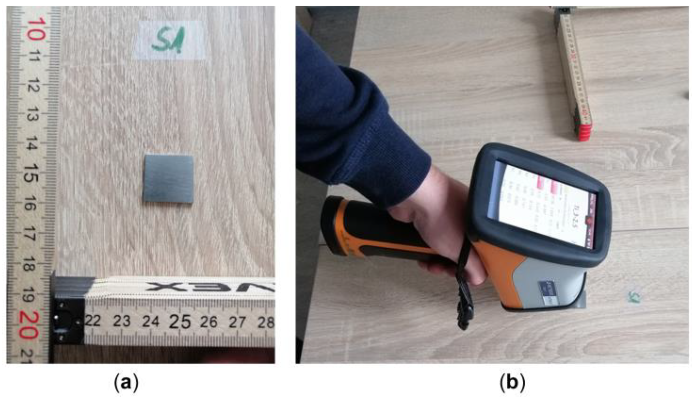
2. Materials and Methods

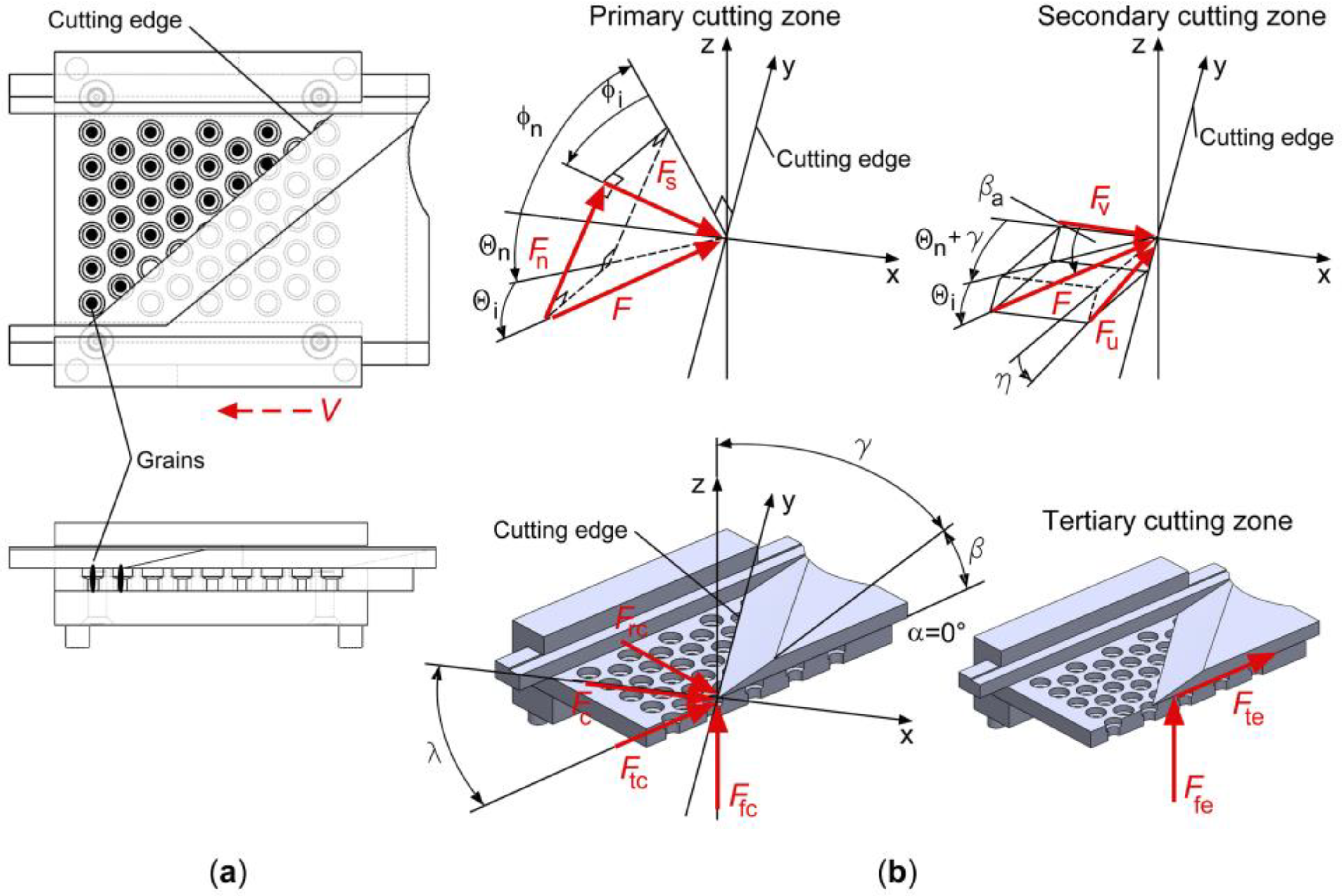
2.1. Methodological Approach Based on New Design of Grain-Cutter Knife/Blade

To improve the grain mowing method with a new blade, wheat samples were obtained from the Osijek Agricultural Institute. As a reference, the vitreosity was determined using a commercial grain cutter (Farinotom, Sadkiewicz Instruments, Bydgoszcz, Poland), as shown in Figure 1 and Figure 2. After cutting, determination of gray (hard, glassy) endosperm was performed visually by three trained analysts. The vitreosity of the cut grains was expressed as a percentage as described in [14,15]. Vitreous grains are translucent and transparent when cut, whereas starchy grains are detected as white and opaque because of air pockets in the endosperm that diffract and scatter light [16]. After evaluating the cut with the old blade, a new blade was made, and three independent experts evaluated the parameters and compared the indicators obtained with the commercial grain cutter and the new blade. The development of a new design solution for the grain cutter was preceded by a detailed analysis of the existing solution, with the aim of improving the quality of the cut and the readability of the grain. A detailed analysis of the technical solution with mathematical descriptions and parameters of the forces acting on the cut is presented in the Section 2.2. During the analysis, special attention was paid to the analysis of the material so that the blade maintains its properties during the explosion phase. The improved technical solution was evaluated by tracking changes in the cutting methods and the trajectory of the lever mechanism. The main parameter that led to the idea of developing a new solution is the force required for the measurement process, which was measured and compared for both, the old and new blades. The aim of the research at this stage was not to measure the force accurately, but to determine its magnitude. The measurement data shows that twelve times less force is required for cuts with the new solution, which, combined with a much clearer cut, confirms the validity of the conceptual solution. The main difference is that the new solution can only cut 25 grains instead of 50 grains due to the cutting process. The hand force measurement on cuter crank is presented graphically, and the comparison itself is made by comparing the maximum load on the blade and the same load, as shown in the figures.

2.2. Proposed Design Solution of New Knife Implemented in Grain-Cutter

Requisite for a new design solution of the knife, arose from the requirement for a more reliable and precise visual analysis of grain’s vitreosity. Vitreosity is determined from grain cross-section analysis. Therefore, it is extremely important that the cross-section of the grain is clean and uniform on each of the grains that are cut using commercially available grain-cutters. For analyzing grain’s vitreosity, a commercial grain-cutter was used (Figure 4), as well as a new design blade solution of grain-cutter (Figure 5), which replaced the cutting knife on the commercial grain-cutter shown in Figure 4.

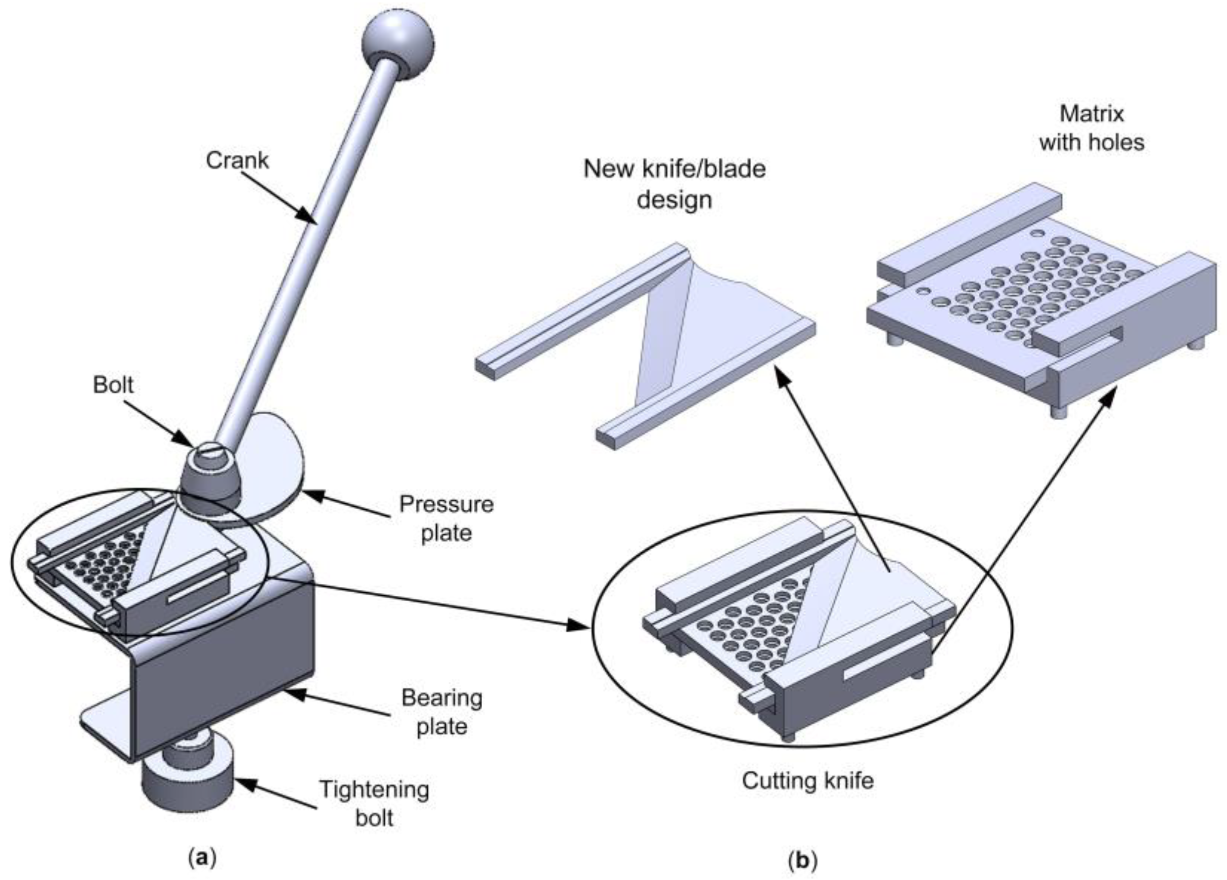
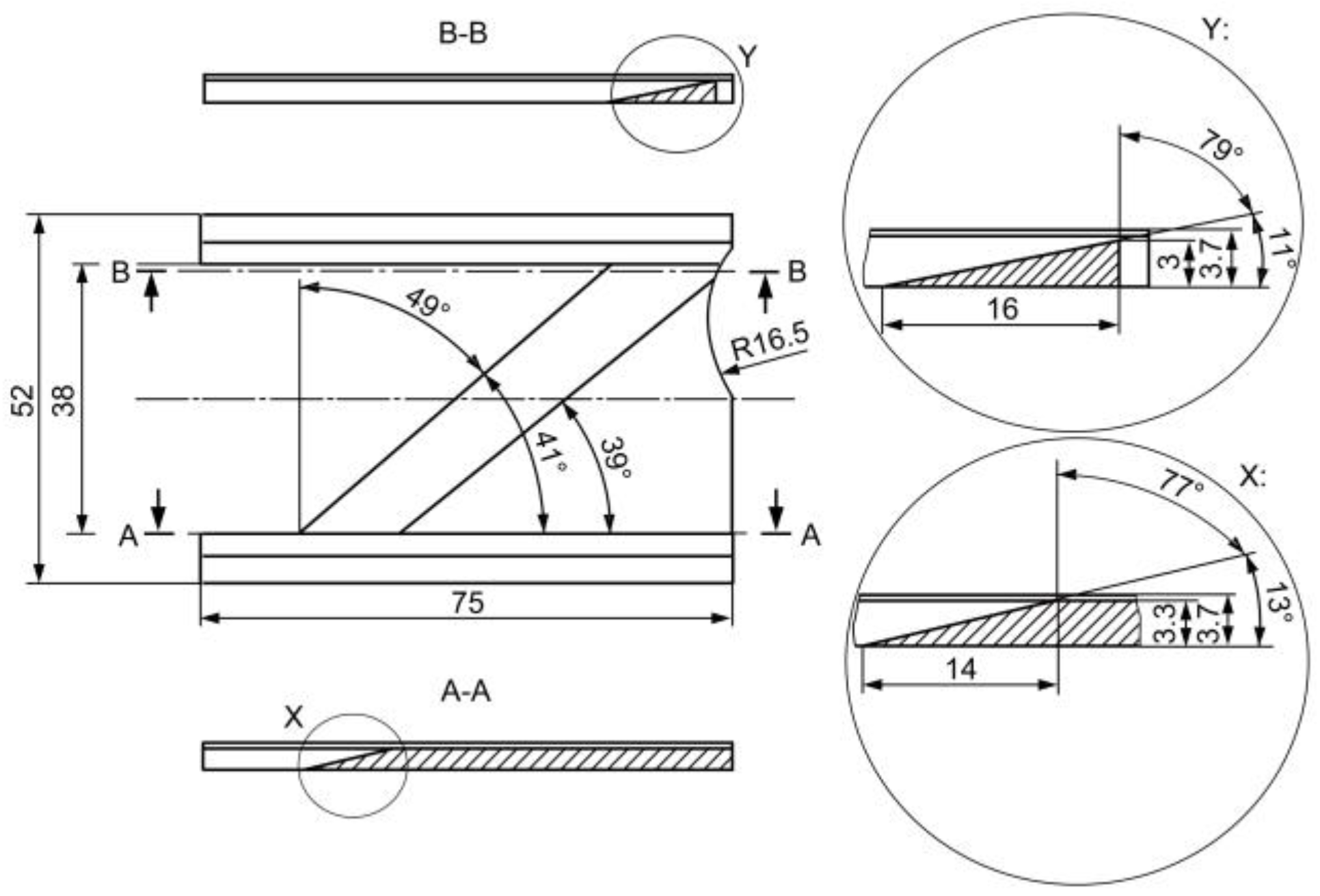
2.2.1. Analysis of the Existing Design Solution of a Commercial Knife for the Grain “Tearing”

Cut obtained by using a commercial grain-cutter with the knife shown in Figure 4, as well as some other commercially available grain-cutters, resulted in the appearance of broken and crushed grains which disables reading and hinders the precision and accuracy.
Due to the design of the knife on a commercial grain-cutter, it is noted that a significant amount of the manual force (Fm) on the cutter crank is required to achieve the torque required to achieve translational movement of the knife within the guides of the matrix with holes (Figure 4 and Figure 5). In order to achieve the desired torque, by the action of manual force on the cutter crank, a yank force occurs. The impulse occurs as a consequence of the yank force. The yank force occurs as a result of the grain’s cutting resistance to the cutting force (Fc) that occurs on the blade of the knife. According to the [17], amount of the cutting resistance is equal to the cutting force, but it is in the opposite direction to the cutting force. This follows from the law of action and reaction.
Construction solution of the commercial knife is made in such a way that it applies the orthogonal cutting method. Characteristics of this method are described in detail in [17]. This means that the knife blade (edge of the knife blade) is perpendicular to the cutting speed (v). In the case when all 50 grains are placed in the holes of the matrix and form a rectangular formation, the tangential component of the cutting force (Ftc) acts perpendicular to the grain and the edge of the blade. Also, this force component, is collinear with the cutting speed (Figure 6a). This is when the greatest resistance of the grain to the cutting force occurs. Therefore, maximum manual force as well as yank force is required to overcome the cutting resistance.
For the case where the grains are placed in the holes of the matrix and form a right triangle formation (24–26 grains), the tangential component of the cutting force (Ftc) also acts perpendicular to the grain and the edge of the blade, and also is collinear with the cutting speed (Figure 6b). The reason why the formation of the grains arrangement in a right triangle was selected, derives from the design performance of the proposed new knife/blade for cutting grains. Number between 24 to 26 grains (depends on the size of each grain diameter) on the existing commercial knife was used precisely in order to be able to compare and analyze the manual force, necessary to create the cutting force on the knife blade in both cases of grain cutting (with a commercial knife and the proposed new design solution of the knife) on samples that have the same number of grains. In this case, a yank force (impulse) also occurs. Its amount is now smaller because the number of grains is also smaller. It can be concluded that the amount of manual force on the crank of the cutter will be smaller, due to the reduction of the number of grains placed in the holes of the matrix and the knife. By analyzing the number of grains placed in the holes of the matrix and the knife, a smaller number of grains creates less resistance to the cutting force, regardless of the formation in which they are arranged in the matrix with holes. Further reduction of the number of grains does not make much sense, because the time required for the analysis of grains is extended, due to the smaller number of grains that can be cut with a knife. The problem of cut quality and grain damage remains unsolved, as and the presence of yank force.
In orthogonal cutting [17], a larger number of components of the cutting force act on the workpiece, in this case on the grain. Components of the total cutting force is difficult to measure and there is a large number of factors that influence on them [17,18,19]. On the amount of the total cutting force, affect cutting speed, stresses in the primary, secondary and tertiary cutting zone, material of the workpiece, material of the knife and the geometry of the knife. At the knife geometry, angles of the knife blade have significant impact on the amounts of the components of the total cutting force [17,18].
In the case of the design of a new knife, which is explained in detail in Section 2.2, by designing of the knife blade angles, a reduction of the total cutting force (cutting resistance) and manual force on the crank is achieved. Also is increased a grain cut quality.
In the primary cutting zone [17,19], a commercial knife has a shear force (Figure 6c), which, according to [17], is:
F s = τ s b h sin ϕ c
where b is width of cut, h is depth of cut, τs is shear stress and ϕc is shear angle.
Perpendicular on the Fs force, acts normal force (Figure 6c):
F n = F tc sin ϕ c + F fc cos ϕ c ,
where, according to [17], tangential force (Figure 6c) is equal:
F tc = b h τ s cos β a γ sin ϕ c cos ϕ c + β a γ .
Feed force (Figure 6c) is described by the expression:
F fc = b h τ s sin β a γ sin ϕ c cos ϕ c + β a γ .
According to [17,19], Equations (3) and (4) describe Ftc and Ffc forces as a function of tool geometry (γ—rake angle of the tool), cutting conditions (h, b) and process-material dependent terms (τs, βa, ϕc). In the primary and secondary cutting zone, appears shear stress (τs) and friction angle (βa).
In the secondary cutting zone acts friction force (Figure 6c) on the rake face:
F u = F tc sin γ + F fc cos γ .
Also acts normal force (Figure 6c) described by the expression:
F v = F tc cos γ F fc sin γ .
On the rake face, when removing the cut material, friction factor appears. Factor is determined by the expression:
μ = tan β a = F u F v ,
where according to [17], βa is friction angle between the tools rake face and the moving of the cut grain (Figure 6c). Certain quantities, such as βa, ϕc, τs, is difficult to determine. Therefore, they are determined empirically and by different prediction methods described in [17,20,21,22,23].
Resultant cutting force (Figure 6c) which acts in the primary and secondary cutting zone, is determined by the expression:
F c = F s cos ϕ c + β a γ = τ s b h 1 sin ϕ c cos ϕ c + β a γ .
Since the angle α = 0°, bottom surface of the knife slides on the top surface of the matrix, and because of this, forces also occur in the tertiary cutting zone. According to [17,19], friction force on the bottom surface of the knife is determined by the expression:
F ff = μ f F fn ,
where μf is friction factor between the bottom surface of the knife and the top surface of the matrix. Normal force is:
F fn = σ f b V B ,
where σf is pressure on the bottom surface of the knife and VB is flank contact length.
Total contact forces who acting in the tertiary zone (Figure 6c) are tangential force:
F te = F fn sin α + F ff cos α ,
and feed force:
F fe = F fn cos α + F ff sin α .
On the commercial knife is drilled 50 conical holes. The larger diameter of the hole (d1) is on the top surface of the knife, and the smaller diameter of the hole (d2) is on the bottom surface of the knife (Figure 7). Edge of the smaller diameter is also the blade of the knife, whose radius of curvature corresponds to the radius of the smaller circle. From the analysis of the knife angles, follows that the cone inclination angle represents blade front angle (γ). Amount of this angle is 8° (Figure 7). Amount of the wedge angle (β) is 82°, while the amount of the rear angle (α) is equal 0° (Figure 7).
It can be concluded that due to the small number of angles γ and α, a large amount of angle β is obtained (Figure 7). Because of this, there is a tearing and damage of the grain, i.e., a reduction in the grain cut quality. From Equations (5)–(7) it can be seen that by increasing the angle γ, the friction force (Fu) in the secondary cutting zone will decrease. By reducing the amount of the force Fu, it effects the reduction of cutting resistance, i.e., the resultant cutting force (Fc).
It can also be concluded that due to the large amount of angle β and the small amount of angle γ, commercial knife blade creates shear stress in the grain, which increases amount of the forces Fs, Fn, Ftc and Ffc in the primary cutting zone. This is evident from Equations (1)–(4). By increasing of the amount of these forces, cutting resistance increases, i.e., Fc force increases. There is also grain “tearing” rather than grain “cutting”. Therefore, Ftc force breaks the grain, creating a grain pinching between the cutting knife and the matrix with holes (Figure 6a,b).
Since the amount of the rear angle (α) is equal to 0°, forces Fte and Ffe appear in the tertiary cutting zone. From Equations (11) and (12), it can be concluded that the influence of the mentioned forces contributes to the wear of the knife. Also, the influence of these forces manifests in an increase of cutting resistance.
After the previously mentioned and described analysis of the commercial knife, a new design solution of the knife/blade was designed, which was implemented on the existing commercial grain-cutter (Figure 5a,b).

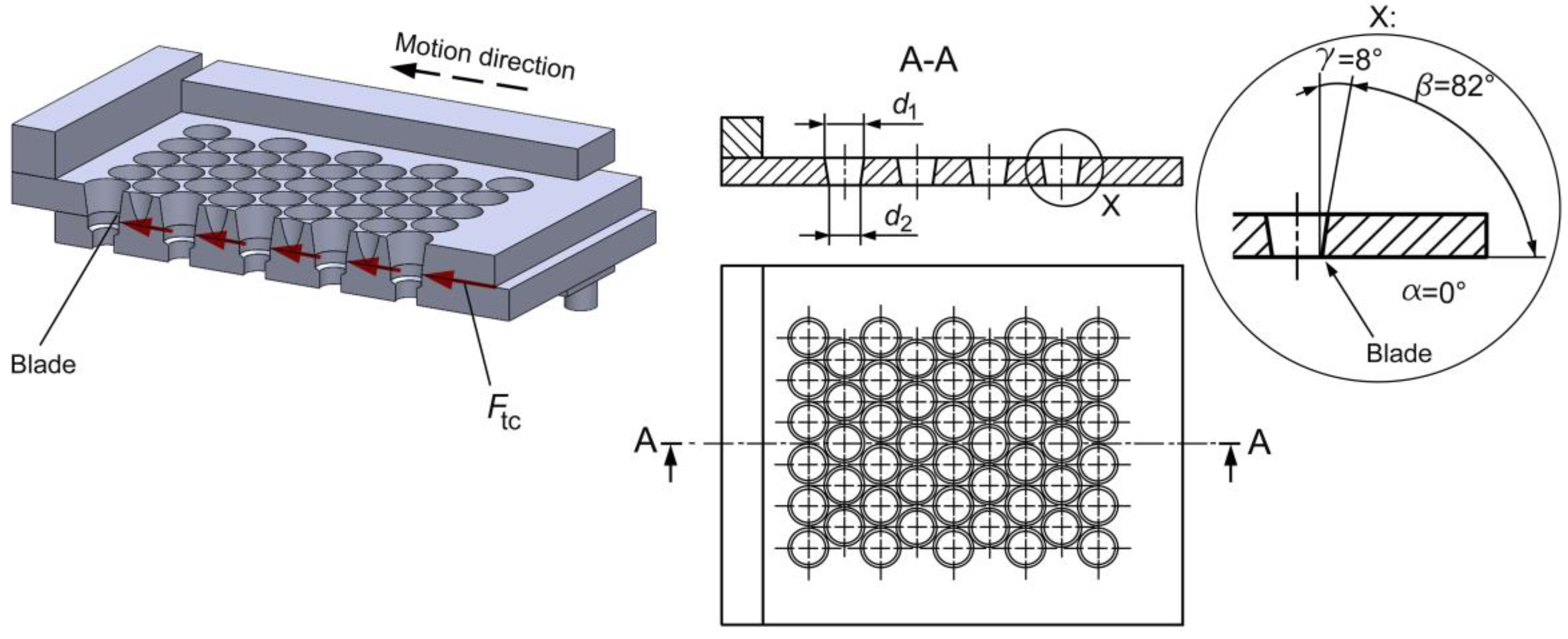
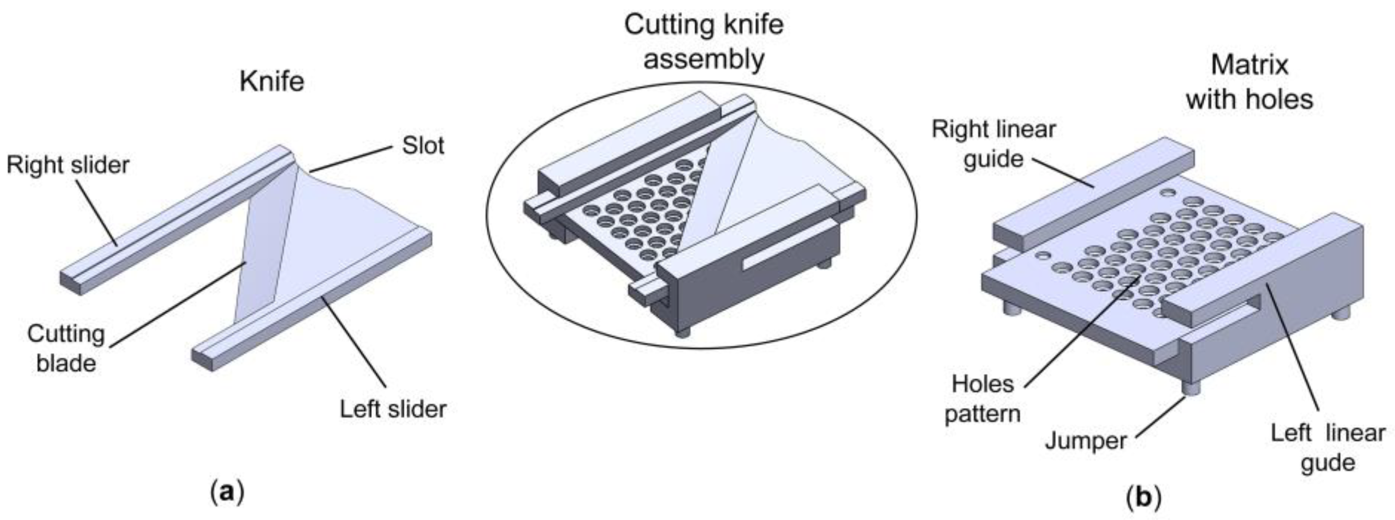
2.2.2. Proposed New Design Solution of the Knife/Blade for Grains “Cutting”

In order to contribute to achieving better grain cutting, reducing cutting resistance, reducing the required manual force on the cutter crank and reducing yank force, a new knife was designed to replace the existing commercial knife on the grain-cutter. In designing of the new knife, it is decided to use oblique cutting method. Since the new knife was implemented on the place of the existing knife (Figure 5a,b), new design of the knife had to accept certain existing solutions that were on the old knife. Thus, new knife achieves a translational motion through the guides of the matrix with holes. Therefore, sliders are constructed on the left and right side of the knife (Figure 8a) that slide through the matrix guides (Figure 8b). Since a knife is placed on the existing matrix with holes, a slight slot is designed on the rear surface of the knife. Amount of the radius of the slot is equal to the amount of the radius of the side surface of the pressure plate (Figure 8a). When is made contact between the rounded surface of the knife slot and the pressure plate, torque is transmitted. Also, the rotary motion of the crank is converted into translational motion of the knife (Figure 5a). When crank is turning, using manual force (Fm), the pressure plate rotates around the vertical axis of the screw (Figure 5a) and its side surface touches the surface of the knife slot and performs a translational motion of the knife along the matrix guides. In order to respect dimensions of the matrix with holes and the design of the pressure plate, as well as the oblique design of the blade of the new knife in relation to the position of the grains placed in the matrix holes (λ = 49°), a right triangle grain formation is used (Figure 9a). In the free holes of the matrix, using right triangle formation, is possible to place between 24 and 26 grains (depends on the size of each grain diameter). This limitation is a consequence of the arising limitations from the requirements for using the existing commercial grain-cutter, as well as the design of the new knife, which in a certain part of its geometry is adapted to the existing grain-cutter.
The amount of the rear angle α = 0° is retained (Figure 9b). Therefore, in the tertiary cutting zone are present forces Fff, Ffn, Fte and Ffe (Figure 9b). These forces are determined by Equations (9)–(12). Therefore, wear of the knife bottom surface and the matrix top surface is still present.
Due to the oblique design of the cutting edge, which is oblique by the inclination angle (λ), in the primary cutting zone appears force Frc (Figure 9b). This force is one of the three components of the resultant cutting force (Fc) in the primary cutting zone (Figure 9b). By projection of the resultant cutting force (Fc) is possible to get expressions for these components. Normal force, according to [17], is expressed by the expression:
F rc = F c sin Θ i cos λ cos Θ i cos Θ n sin λ = = τ s b h tan Θ i cos Θ n tan λ cos Θ n + ϕ n cos ϕ i + tan Θ i sin ϕ i sin ϕ n
where θi and θn are angles of direction of measured total resultant cutting force (F), ϕi and ϕn are oblique shear angles (Figure 9b).
Force component in the direction of cutting speed (tangential force) is determined by expression:
F tc = F c cos Θ i cos Θ n cos λ + sin Θ i sin λ = = τ s b h cos Θ n + tan Θ i tan λ cos Θ n + ϕ n cos ϕ i + tan Θ i sin ϕ i sin ϕ n
Feed force is described by expression:
F fc = F c cos Θ i sin Θ n = = τ s b h sin Θ n cos Θ n + ϕ n cos ϕ i + tan Θ i sin ϕ i sin ϕ n cos λ
Toward to minimum energy principle [23], resultant cutting force in the primary cutting zone is determined by expression:
F c = τ s b h cos Θ n + ϕ n cos ϕ i cos Θ i + sin Θ i sin ϕ i sin ϕ n cos λ .
Shear force (Figure 9b), according to [17], is:
F s = τ s b cos λ h sin ϕ n .
Normal force (Figure 9b), according to [17] is:
F n = F c cos Θ i cos Θ n + ϕ n sin ϕ i sin Θ i cos ϕ i .
In the secondary cutting zone (Figure 9b) acts friction force on the rake face:
F u = F c sin β a = F sin Θ i sin η ,
where η is angle of grain flow direction. Normal force (Fv) is determined from Equation (7).
As a result of the oblique of the knife blade by an angle λ, appeared force Frc (Figure 9b). This component of the cutting force contributes to the fact that the force Fc in the primary cutting zone acts on the grain at the angle λ (Figure 9b). On this way, a gradual grain cutting is achieved, during a translational movement of the knife blade in the direction of the cutting speed (v). From the Equation (17), it is possible to see that by increasing of the inclination angle (λ), decrease forces Fs and Fc. On this way, cutting resistance is reduced. By increasing of the angle γ and decreasing of the angle β, cutting resistance decreases. Also due to the reduction of the angle β and acting of the force component Frc, a better grain cut is achieved.
A detailed representation of the geometry of the new grain-cutting knife is shown on Figure 10. Blade of the knife is made with the variable geometry. This is evident from the amount of the angles β and γ in the sections A-A and B-B (Figure 10). Amount of the angle γ in section A-A is 77° and in section B-B is 79°. Changing amount of these angles, it is contributed to an additional reduction of the cutting resistance, as well as a better removal of the cut grain in the direction of angle η. According to [17], this angle is determined by expression:
tan η = tan λ cos ϕ n γ cos γ tan ϕ i sin ϕ n .
Obtained angle values of the new knife (Figure 10) are achieved after grain cuts with different angle values were performed. Several knife prototypes with different angle variants are made and tested. Based on the analyzes of the grain cuts, which were made using knife prototypes, a design solution that gave the best results in terms of the cut quality and required manual force for achieve a grain cut is selected (Figure 10).
From a technological reasons, amount of wedge angle β = 11°, is not advisable to reduce on a smaller amount. Reducing the value of the angle β would cause mechanical damage on the cutting edge of the blade. Amount of the angle λ could be greater than the amount shown in Figure 10. Due to the design limitation of the slot on the knife (Figure 9 and Figure 10), amount of this angle should be 49°.
The new knife is made of steel, the chemical composition of which must be checked, since the new blade is more prone to wear due to its design and longer cutting path; therefore, it is important to check whether the material used is tool steel, which ensures a longer life. Chemical composition was examined using an X-ray analyzer X-MET8000 Expert-Hitachi (Figure 11). Result of the analysis of the chemical composition, made on a sample of the steel used to make the knife, is shown in Table 1. Steel mark provided by the X-ray analyzer database is 1.0167. According to the DIN 17100 [24] and EN 10025 [25] standards, to this mark corresponds marks that indicate constriction steel St37-2, or S235JR.

3. Results and Discussion

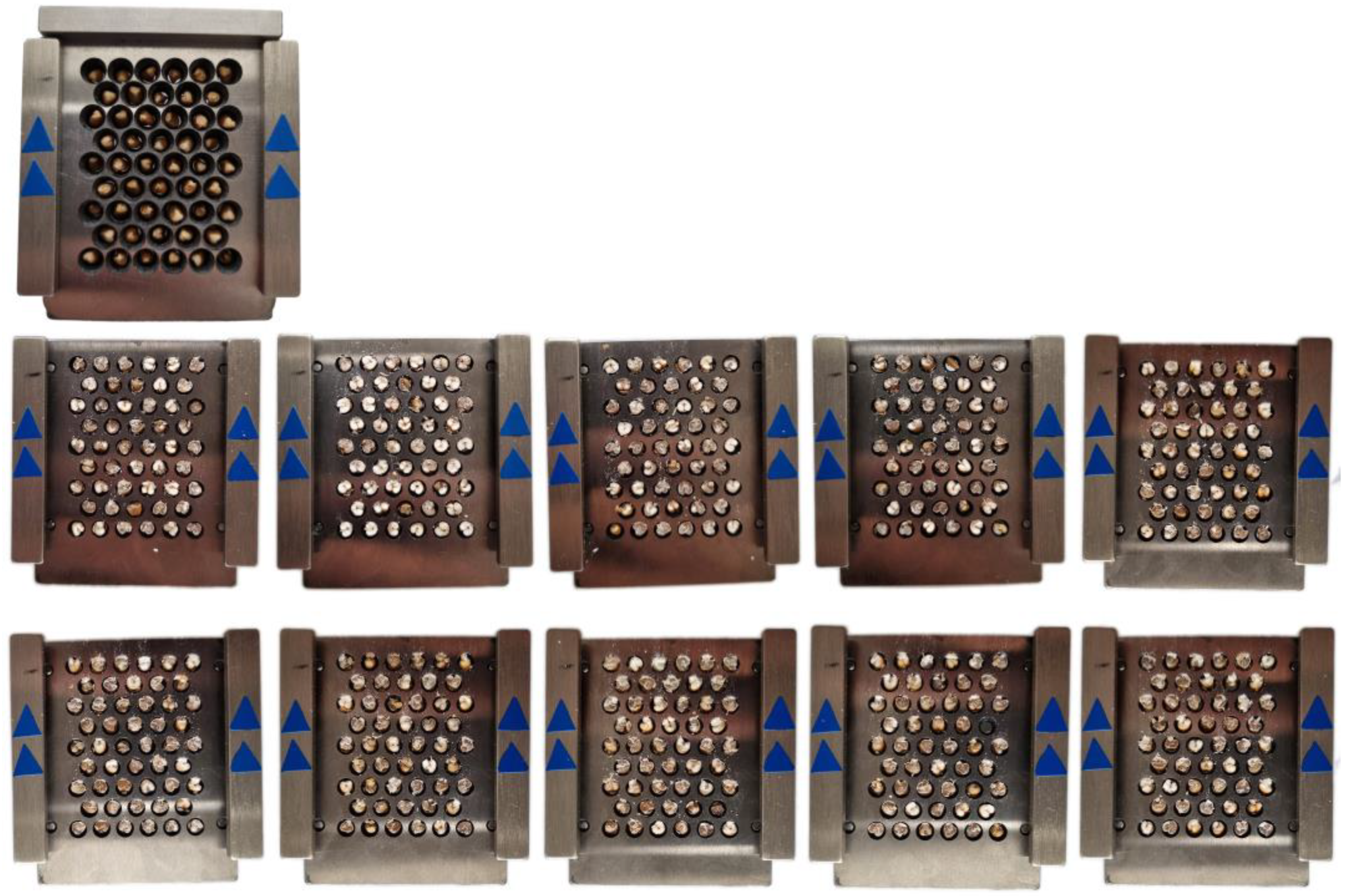
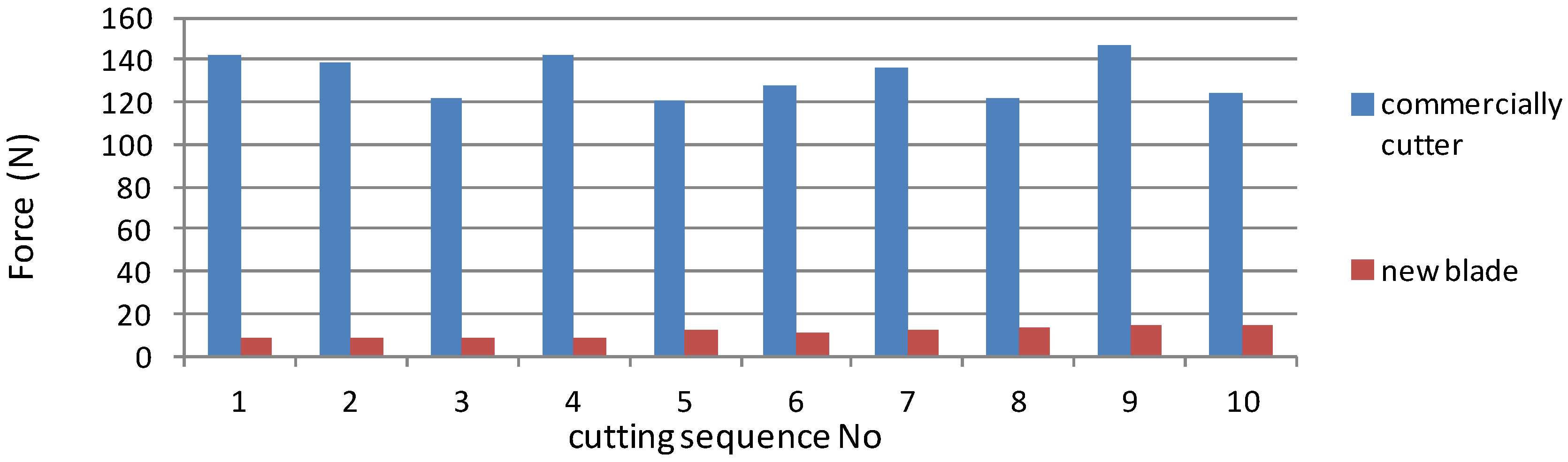
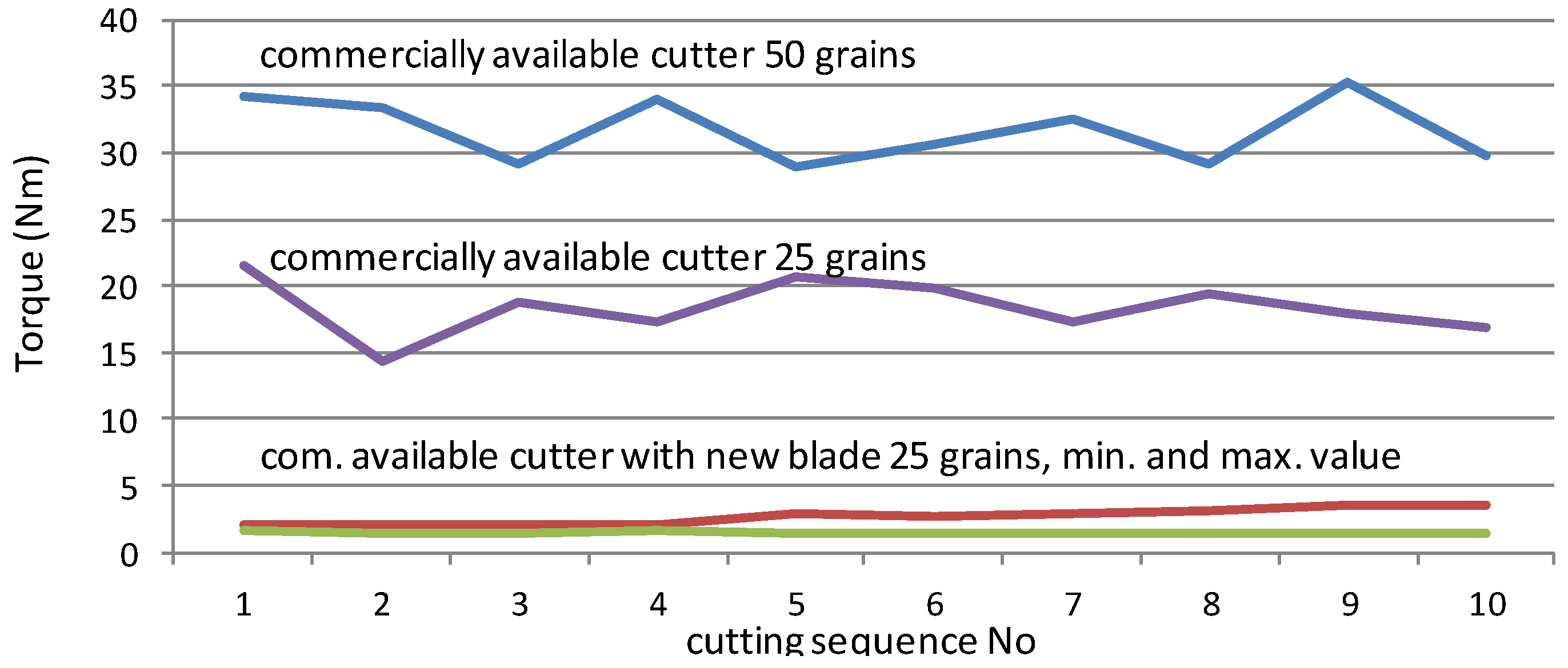
3.1. Results of the Grain Cutting with the Commercial Avialble Grain Cutter (Standard Knife) vs. the Improved Grain Cutter (New Knife)

Comparison of the quality of the grain and the cutting itself was performed on ten samples, using a visually homogeneous sample. The cutting of wheat samples with a commercial grain cutter is shown in Figure 12.
A commercial grain-cutter accommodates 50 grains inside the holes of matrix and standard knife, and the cutting process requires considerable force, that can often move the entire grain-cutter. It can be seen from 10 examples that the quality of the cut, in addition to the deviations, leads to an effort in the evaluation due to irregularities caused by tear-out (Figure 12). Implemented new knife on a commercial cutter and the corresponding 10 examples used to evaluate the vitrification is shown on Figure 13.
Ten different samples were independently rated by three independent experts; their ratings are shown in Table 2. The mean values of the assessments show an average deviation of 13.29%, which is a significant difference between the use two different blades.
The detailed statistical analysis in Table 3 shows better the quality of the new knife, which is reflected in the lower deviation of the rating of three independent experts.
During cutting using commercially available farinotom, the grain breaks or crushes This results in uneven cutting surface which causes the light to scatter and causes discrepancies between gray and white color of endosperm. This causes errors in readings since the colors are not strictly divided. This can be seen in Table 2 and Table 3. A significant deviation between the same samples analyzed by different analysts (higher SD values for the standard knife). On the other hand, the results of vitreosity determined after the usage of a new knife, showed lower SD between the trained analysts. The new knife cuts the grain in half, resulting with a smoother cutting surface (Figure 13) which enables a better reading of the results. This can indicate that the results obtained using the new knife are more reliable for this kind of reading.
Furthermore, the standard farinotom knife/blade breaks the grain, the force needed to complete the cut is bigger than the force needed for the new blade which cuts the grain in half. This can result in errors in reads out since the moment of force applied to cut with the standard knife is greater than the one when using the new knife.

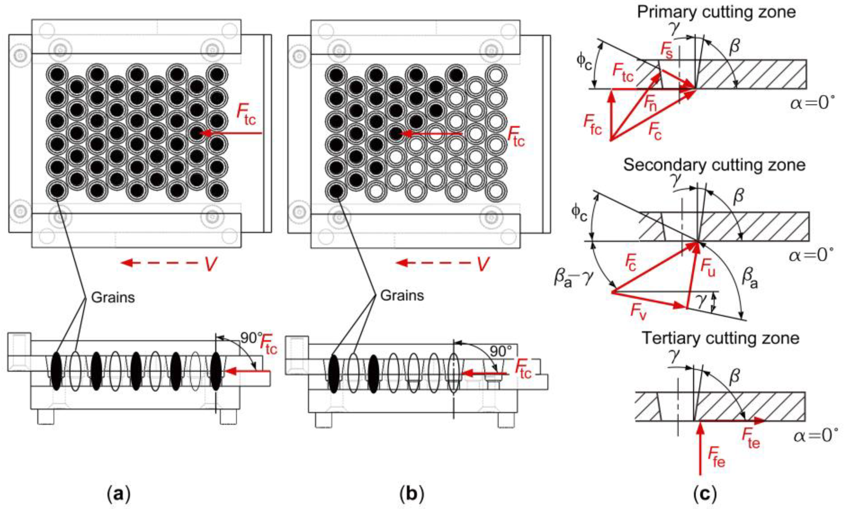
3.2. Analysis of “Tearing” and “Cutting” by Comparing Existing and New Design Solution of the Grain-Cutter Knife

Depending on the rotation angle of the cutter crank, due to the action of the manual force, we determined when the “tearing” of the grain occurs, using an old commercial knife. When the crank is in the reference plane (plane from which we start to measure rotation angle), amount of the rotation angle is 0° (Figure 14a). Also, when the crank of the grain-cutter is in the neutral position, there is no contact of the side surface of the pressure plate with the rear surface of the knife. The neutral position represents the end position to which is possible to move the crank, by the action of the manual force on its outer end, opposite to the direction of clockwise movement. Therefore, a reference plane is placed through the central axis of the grain-cutter crank when the crank is in its neutral position. Reference plane is shown as a straight line when viewed from above grain-cutter (Figure 14a). By turning of the grain-cutter crank from the reference plane in a clockwise movement to the amount of the rotation angle of 20°, appears an idle stroke (Figure 14b). During idle stroke, a translational movement of the commercial knife is achieved. In that moment there is no contact between the blades of the knife and the grains. When there is no contact between the knife blades and the grains, then there is no deformation of the grains. We called that idle stroke. At angle of 20°, occurs contact between the edge of the knife blade and the outer surface of the grain. Between the edge of the blade and the surface of the grain, occurs a short-term slipping and friction. Then appears grain “tearing”. Because of the beginning of the “tearing”, a grain resists to the cutting force on the blade of the knife. In order to overcome the resistance of the grain, it is necessary to increase amount of the manual force on the cutter crank. As a result of the manual force increasing, a yank force appears which creates impulse. Because of the yank, which occurs due to the yank force, a blade of the knife moves and tears the grain. Also, a grain damage and poor cut quality appears. Active “tearing” occurs at a rotation angle of the crank from 20° to 45° (Figure 14c). When the angle of 45° is reached, a “tearing” of all grains that were placed in the holes of the matrix is achieved.
By installing a new design solution of the knife on a commercial grain-cutter, grain “cutting” is achieved. When the crank is in the reference plane, amount of the rotation angle is 0° (Figure 15a). By applying the manual force to the crank, crank rotates around the bolt. Knife begins to move translationally through the matrix guides. At that moment, occurs a contact between the knife blade and the grains. Also, a shear stress appears. This stress is caused by the action of the cutting force (Fc) on the grains placed in the holes of the matrix. Cutting force occurs in the primary cutting zone. Between the knife blade and the grains, occurs a short-term slipping and friction. Therefore, is possible to define a cutting zone, which starts from the reference plane and ends when is achieved amount of 150° of the rotation angles (Figure 15b). At the amount of rotation angle from 150° to 180°, a translational movement of the knife continues, but without the action of the cutting force (Figure 15c).
Change in construction did not only change the rotation angle but also the required force (manual force) on the cutter crank. The measurement of the required force was carried out with a portable electronic scale 40 kg ± 10 g. The scale used is a common device often find in toolbox with the grind cutter. Since at this stage of the test only the magnitude, i.e., only the main values of the force need to be determined, the existing measuring device is satisfactory in terms of accuracy and precision. In order to be able to carry out the measurement due to the limited measured range, the crank was extended to 84 cm with a standard length of pipe used for furniture production (Figure 16a).
Figure 16a shows the extension lever with the attached scale and measuring tape. Figure 16b shows the maximum registered force before the actual grain cut. The angle at which the cut is made with the old knife is short, and the position itself depends on the thickness of the grain. Figure 16c shows the moment of cutting through the grain, which can be seen by the sudden drop in force visible through the smeared recording. When the knife is replaced, shown in Figure 16d, the extension of the lever is not needed because the force is reduced, and the scale can register the force amounts normally. Figure 16e shows the maximum initial force at which the largest number of grains are on the blade of the knife, and towards the end of the cut the number of grains and the force of the cut decrease, as seen in Figure 16f. Amount of the average manual force of a commercial knife is 132.27 N, while the maximum amount of the manual force when using a new blade is 11.22 N, which is almost twelve times less (Figure 16).
The required force can be reduced by increasing the size of the crank, but this solution does not reduce the problem of fixing the device, since the required torque does not change. In order for the comparison to be valid, i.e., to be reduced to a single grain, we performed the measurement with the original knife filled with the same number of grains that the new knife can accommodate. The average hand force when using a commercial knife filled with 25 grains is 76.74 N. With the new knife, due to the design of the blade, the average hand force is 11.22 N at the beginning of the cut and decreases to 6.08 N toward the end of the cut (Figure 17). Figure 18 shows that the torque averages 31.74 Nm when using a standard blade equipped with 50 grains, 18.55 Nm when using a commercial knife loaded with a new blade capacity of 25 grains, and the maximum and minimum torque when using the new blade is 2.69 Nm. The 91.51% reduction in torque (in the case of 50 grains versus 25 grains with a new knife, or 85.48% for the same grain size) significantly reduces operator strain and facilitates the analysis of vitreosity.
The results of the performed analysis show the advantages of the new solution, but for a complete analysis it is necessary to mention possible disadvantages. With the design solution of the new knife installed in the commercial grain cutter, it is possible to cut between 24 and 26 grains at the same time. This design limitation is due to two reasons. The first reason is that the new knife is installed in the existing matrix of the commercial grain cutter in order to respect the existing dimensions of the grain cutter. The second reason is that the blade of the new knife is at an angle of inclination of 49° with respect to the position of the grains placed in the matrix holes. The commercial knife used in the commercial grain cutters can cut 50 grains at the same time. This is the first limitation of the new knife. The second limitation relates to knife wear. In the commercial and the new knives, the back angle (α) is equal. The amount of this angle is 0°. For this reason, the undersides of the commercial and the new knives slide on the upper side of the die, which causes wear of the knives. The wear is greater for the new knife because the amount of the angle of rotation in the cutting zone of a new knife is greater than the amount of the angle of rotation in the tear-off zone of a commercial knife (Figure 14c and Figure 15b). During the translational motion of the new knife, the new knife travels a longer distance than the commercial knife due to the larger angle of rotation. For this reason, the wear of the underside of a new knife is greater. The third limitation refers to the mechanical damage of the knife blade. In a new knife, the front blade angle (γ) is larger than in a commercial knife (Figure 7 and Figure 10). For this reason, the wedge angle (β) of the new knife blade is smaller than the wedge angle of the commercial knife blade (Figure 7 and Figure 10). When cutting grains with a new knife, the blade of the new knife is mechanically damaged earlier than when cutting grains with the blade of a commercial knife.

4. Conclusions

Vitreosity as property of wheat is usually determined by the ICC visual method Standard 129, which is based on the Pohl’s grain cutter. To make a valid visual inspection of the grain, the cut must be clean and clear. The commercial knife design presented in this paper is not well suited for this purpose, and the cut often breaks or crushes. Another problem with the commercial knife design is the force required, which is 132 N on average. The contribution of the paper is to upgrade the existing device with a new blade and to design a new cutting blade that provides better cutting quality. The basic hypothesis of the work, that better cutting leads to a reduction in the deviation of the value for the evaluation of vitrification, which is the first step towards computer evaluation and automation of the process to achieve uniform quality of grain products in real time, is confirmed by the results of the analysis of three independent experts. Thanks to the new blade solution, it was possible to increase the quality of the grain cut and reduce the manual force required to move the knife by developing a new geometry of the grain cutting knife. By designing a knife whose blade has an angle of inclination of 49°, it was possible to achieve an oblique cut. By placing the blade of the knife at an angle λ, the Frc force was created. This component of the cutting force contributes to the force Fc acting on the grain in the primary cutting zone at an angle λ. In this way, gradual cutting of the grain by the blade of the knife was achieved and the resistance to cutting the grain was reduced. The smaller wedge angle compared to the commercial knife also contributed to the reduction of the grain cutting resistance. When the resistance to cutting the grain is lower, less manual force is required on the knife crank to move the knife. Based on manual force measurements with a commercial knife and a new knife, the amount of manual force obtained with the new knife is nearly twelve times lower. By reducing the angle β and the effect of the force component Frc, a better grain cut was obtained. Also, the tensile force that rotated the entire grain cutter and produced an inaccurate cut when using a commercial knife is completely eliminated. The average hand force of a commercial knife is 132.27 N, while the maximum hand force when using a new knife is 11.22 N. The reduction in torque (to move the knife from the attachment point) is 91.51% for 50 grains compared to 25 grains with a new knife, or 85.48% for the same grain size. The numerical data obtained show that the operator’s load is significantly reduced, and the analysis of glassiness is facilitated, which confirms the usefulness of the new design.

Author Contributions

Conceptualization, M.K. and K.M.; methodology, K.M., M.K. and H.G.; software, M.K.; validation, M.K., K.D. and K.H.; formal analysis, K.M., M.K., K.H. and H.G.; investigation, K.M., M.K. and H.G.; resources, K.D. and M.K.; data curation, K.H., M.K., K.M. and K.D.; writing—original draft preparation, K.H., K.M., M.K. and H.G.; writing—review and editing, K.M., K.H. and M.K.; visualization, M.K., K.M. and H.G.; supervision K.M.; project administration, K.H. and K.M.; funding acquisition, K.M. and K.D. All authors have read and agreed to the published version of the manuscript.

Funding

This research received no external funding.

Institutional Review Board Statement

Not applicable.

Informed Consent Statement

Not applicable.

Data Availability Statement

Data are available upon request to the corresponding author.

Acknowledgments

Authors express their tanks to Center of Competence for Advanced Engineering Nova Gradiška (CEKOM), who through the EU project CEKOM NI NG (KK.01.2.2.03.0011), made it possible to test the chemical composition of the steel sample used for design of a new prototype solution of a grain-cutting knife, using X-ray analyzer X-MET8000 Expert-Hitachi. Authors also express their gratitude Josip Karakašić, who, according to the author’s technical documentation and 3D CAD models, created prototype solutions of the grain-cutting knife. Also, authors express their tanks to Iva Samardžić, mag. ing. mech. and Mirela Brechelmacher, mag. ing. mech. for sample preparation.

Conflicts of Interest

The authors declare no conflict of interest.

References

  1. Samson, M.-F.; Mabille, F.; Chéret, R.; Abécassis, J.; Morel, M.-H. Mechanical and physicochemical characterization of vitreous and mealy durum wheat endosperm. Cereal Chem. 2005, 82, 81–87. [Google Scholar] [CrossRef]
  2. Dowell, F.E. Differentiating vitreous and nonvitreous durum wheat kernels by using near-infrared spectroscopy. Cereal Chem. 2000, 77, 155–158. [Google Scholar] [CrossRef] [Green Version]
  3. Dexter, J.E.; Williams, P.C.; Edwards, N.M.; Martin, D.G. The relationships between durum wheat vitreousness, kernel hardness and processing quality. J. Cereal Sci. 1988, 7, 169–181. [Google Scholar] [CrossRef]
  4. Dexter, J.E.; Marchylo, B.A.; MacGregor, A.W.; Tkachuk, R. The structure and protein composition of vitreous, piebald and starchy durum wheat kernels. J. Cereal Sci. 1989, 10, 19–32. [Google Scholar] [CrossRef]
  5. Pasha, I.; Anjum, M.F.; Morris, C.F. Grain Hardness: A Major Determinant of Wheat Quality. Food Sci. Technol. Int. 2010, 16, 511–522. [Google Scholar] [CrossRef] [PubMed]
  6. Bilgin, O.; Korkut, K.Z.; Baser, I.; Daglioglu, O.; Oztürk, I.; Balkan, A.; Kahraman, T. Variation and heritability for some semolina characteristics and grain yield and their relations in durum wheat (Triticum durum Desf.). World J. Agric. Sci. 2010, 6, 301–308. [Google Scholar]
  7. MEBAK (Middle European Brewing Analysis Commission), Band I and Band II. Brautechnische Analysenmethoden, 3rd ed. (4.1.3.5.1); Selbstverlag der MEBAK: Freising-Weihenstephan, Germany, 1997; pp. 64–66. [Google Scholar]
  8. Sieber, A.N.; Würschum, T.; Friedrich, C.; Longin, H. Vitreosity, its stability and relationship to protein content in duru wheat. J. Cereal Sci. 2015, 61, 71–77. [Google Scholar] [CrossRef]
  9. Dexter, J.E.; Edwards, N.M. The implications of frequently encountered grading factors on the processing quality of durum wheat. Tec. Molit. 2001, 52, 553–566. [Google Scholar]
  10. Baasandorj, T.; Ohm, J.B.; Simsek, S. Effect of dark, hard, and vitreous kernel content on protein molecular weight distribution and on milling and breadmaking quality characteristics for hard spring wheat samples from diverse growing regions. Cereal. Chem. 2015, 92, 570–577. [Google Scholar] [CrossRef]
  11. Konopka, I.; Tanska, M.; Konopk, S. Differences of Some Chemicals and Physical Properties of Winter Wheat Grain of Mealy and Vitreous Appearance. Cereal. Res. Commun. 2015, 43, 470–480. [Google Scholar] [CrossRef] [Green Version]
  12. International Association for Cereal Science and Technology (ICC). 129 Method for Determination of the Vitreousness of Durum Wheat; Quality Assurance and Safety of Crops & Foods ISSN 1757–8361; ICC—International Association for Cereal Science and Technology: Vienna, Austria, 1980. [Google Scholar]
  13. Branković, G.; Dodig, D.; Zorić, M.; Surlan-Momirović, G.; Dragičević, V.; Djurić, N. Effects of climatic factors on grain vitreousness stability and heritability in durum wheat. Turk. J. Agric. For. 2014, 38, 429–440. [Google Scholar] [CrossRef]
  14. Kaluđerski, G.; Filipović, N. Methods of Analysis Grain Quality; University of Novi Sad: Novi Sad, Serbia, 1998. [Google Scholar]
  15. Hoseney, R.C. Structure of cereals. In Principles of Cereal Sciences and Technology; Hoseney, R.C., Ed.; AACC: St. Paul, MN, USA, 1986; pp. 1–33. [Google Scholar]
  16. Jańczak-Pieniążek, M.; Buczek, J.; Kaszuba, J.; Szpunar-Krok, E.; Bobrecka-Jamro, D.; Jaworska, G. A comparative assessment of the baking quality of hybrid and population wheat cultivars. Appl. Sci. 2020, 10, 7104. [Google Scholar] [CrossRef]
  17. Altintas, Y. Manufacturing Automation, 2nd ed.; Cambridge University Press: New York, NY, USA, 2012. [Google Scholar]
  18. Guillemot, N.; Beaubier, B.; Braham, T.; Lartigue, C.; Billardon, R. A hybrid approach to predict residual stresses inducted by ball-end tool finishing milling of a bainitic steel. Adv. Mater. Res. 2011, 223, 391–400. [Google Scholar] [CrossRef]
  19. Stähl, J.E.; De Vos, P. Metal Cutting Theories in Practice; Seco: Lund-Fagersta, Sweden, 2014. [Google Scholar]
  20. Krustof, J. Berichte uber Betriebswissenschaftliche Arbeiten; VDI Verlag: Duesseldorf, Germany, 1939. [Google Scholar]
  21. Lee, E.H.; Shaffer, B.W. Theory of plasticity applied to the problem of machining. J. Appl. Mech. 1951, 18, 405–413. [Google Scholar] [CrossRef]
  22. Royer, R.; Laheurte, R.; Darnis, P.; Gérard, A.; Cahuc, O. Strain gradient plasticity theory applied to machining. In Proceedings of the 14th International Esaform Conference on Material Forming, Belfast, UK, 27–29 April 2011. [Google Scholar]
  23. Merchant, M.E. Mechanics of the metal cutting process. J. Appl. Phys. 1945, 16, 267–279. [Google Scholar] [CrossRef]
  24. DIN 17100-1980; Steel For General Structural Purposes. Quality Standard. Deutsche Normen: Sigmaringen, Germany, 1980.
  25. EN 10025-2: 2004; Part 2: Technical Delivery Conditions for Non-Alloy Structural Steels. European Commission: Brussels, Belgium, 2004.
Figure 1. Clear cut of the wheat grain (mealy, partly vitreous and vitreous).
Applsci 13 02655 g001
Figure 2. Commercially available Pohl’s grain cutter.
Applsci 13 02655 g002
Figure 3. Grain cutter with commercial available Pohl’s grain cutter.
Applsci 13 02655 g003
Figure 4. 3D CAD model of commercial available grain-cutter: (a) commercial grain-cutter assembly; (b) cutting-knife assembly.
Applsci 13 02655 g004
Figure 5. 3D CAD model of modified grain-cutter: (a) modified grain-cutter assembly; (b) new design of knife/blade.
Applsci 13 02655 g005
Figure 6. Force distribution in orthogonal cutting method: (a) rectangular grain formation; (b) right triangle grain formation; (c) components of cutting force.
Applsci 13 02655 g006
Figure 7. Design variant of commercial knife.
Applsci 13 02655 g007
Figure 8. New design solution of cutting knife: (a) new design of knife/blade; (b) commercial grain-cutter matrix.
Applsci 13 02655 g008
Figure 9. Oblique cutting method in new design solution of the cutting knife: (a) right triangle grain formation; (b) components of cutting force.
Applsci 13 02655 g009
Figure 10. Detailed representation of the geometry of the proposed new grain-cutting knife design solution.
Applsci 13 02655 g010
Figure 11. Examination of the steel chemical composition with an X-ray analyzer: (a) sample; (b) X-ray analyzer X-MET8000 Expert-Hitachi.
Applsci 13 02655 g011
Figure 12. Cuts of the 10 wheat varieties with commercial available grain cutter (standard knife).
Applsci 13 02655 g012
Figure 13. Cuts of the 10 wheat varieties with improved Pohl’s grain cutter (new knife).
Applsci 13 02655 g013
Figure 14. Rotation angles of the grain-cutter crank with implemented a commercial knife: (a) rotation angle 0°; (b) rotation angle 20°; (c) “grain tearing”.
Applsci 13 02655 g014
Figure 15. Rotation angles of the cutter crank at the new knife: (a) rotation angle 0°; (b) “cutting”; (c) rotation angle 180°.
Applsci 13 02655 g015
Figure 16. Photos of the measurement setup, (a) extended lever for optimal measurement range, (b) acquisition of the maximum value, (c) the moment of breaking the grain, (d) measurement setup with a new knife, (e) the maximum value of the force at the beginning of the cut due to the largest number of grains affected by the knife, (f) reduction of the force due to the decrease in the number of grains on the knife blade.
Applsci 13 02655 g016
Figure 17. Measured manual force on the commercial and new knife.
Applsci 13 02655 g017
Figure 18. Torque values obtained by measuring of the manual force on the commercial and new knife.
Applsci 13 02655 g018
Table 1. Results of determining of the steel chemical composition.
ElementFeTiMnCuCrZnNiCoMo
%96.431.730.540.370.310.280.250.050.04
Deviation, ±0.1540.0350.0150.0130.0110.0100.0140.0040.004
Table 2. The degree of the vitreous of the wheat sample determined by analysts.
VarietyAnalystsTotal Vitreous Grain Cutter (New Knife)Total Vitreous Grain Cutter (Standard Knife)
(%)(%)
1A4840
1B4743
1C4937
2A6850
2B6652
2C6946
3A6440
3B6143
3C6336
4A5652
4B5355
4C5547
5A5260
5B5152
5C5063
6A6546
6B6450
6C6240
7A5156
7B5450
7C5561
8A5958
8B6050
8C5762
9A5256
9B5458
9C5451
10A3844
10B3739
10C4049
Table 3. The average values of vitreous of the wheat sample (10 varieties).
VarietyTotal Vitreous
Pohl’s Grain Cutter
(New Knife)
Total Vitreous
Pohl’s Grain Cutter
(Standard Knife)
(%)(%)
148.00 ± 1.0040.00 ± 3.00
267.67 ± 1.5349.33± 3.06
362.67 ± 1.5339.67± 3.51
454.67± 1.5339.62± 4.04
553.15± 1.0046.92± 5.69
655.40± 1.5337.27± 5.03
753.33± 2.0855.67± 5.51
858.67± 1.5356.67± 6.11
953.33± 1.5555.00± 3.60
1038.33± 1.5344.00 ± 5.00
Values are mean of three measurements ± standard deviation.
Disclaimer/Publisher’s Note: The statements, opinions and data contained in all publications are solely those of the individual author(s) and contributor(s) and not of MDPI and/or the editor(s). MDPI and/or the editor(s) disclaim responsibility for any injury to people or property resulting from any ideas, methods, instructions or products referred to in the content.

