Abstract
Current batteries of battery electric vehicles (BEVs) require a battery management system (BMS) in order to enable a safe and long-lasting operation. The main functions of the battery management systems are a continuous monitoring of the voltage of each cell, a continuous monitoring of the battery temperature, the control of the charge current and the discharge current as well as the prevention of both a deep discharge and an overcharging. For the realization of these functions, different architectures are possible, ranging from an individual intelligent system at each cell up to a realization of the whole BMS within one central computing unit for the whole vehicle. This paper investigates and structures different architectural possibilities, discusses analysis possibilities and presents approaches for the synthesis of sensible architectures such as BMS. A concept synthesis for the start-up and shut-down of the high-voltage system is presented by comparing three different integrated pre- and discharging circuits and using a Hardware-in-the-Loop (HiL) program as an example. Finally, a topology consisting of three switches and two resistors (3S2R2) turns out to be the best one, due to the number of components, safety and price.
1. Introduction
Since sales of battery electric vehicles (BEVs) and hybrid electric vehicles (HEVs) keep growing rapidly, and both common car manufacturers such as Mercedes [1], Volkswagen [2], Ford [3] and new manufactures (Rivian, Rimac, Polestar, Tesla) are going to produce only EVs in the future, the demand on reliable BMSs is growing fast. Modular electric vehicle platforms [4,5] establish on the world market, but also different approaches of electrical and electronic (E/E) -architectures and BMSs are made. While the BMS in a car tries to operate the battery in a safe and optimal way at the same time, a well working E/E-architecture is essential as well. Nowadays, in cars powered by combustion engines, many electric control units (ECUs) are required to process the amount of data. Therefore, top segment cars use up to 100 different ECUs [6]. Whereas, present E/E-architectures consist out of many ECUs; manufacturers try to reduce this number in the upcoming future. Besides the reduction of ECUs, new software-based features such as “over the air” (OTA) updates and therefore more software embedded functions, require at least a domain-oriented architecture of the E/E environment. Today’s still common decentralized E/E-architectures suffer from major disadvantages. Different communication systems and system processes can barely be overwritten and changed once an ECU is programmed. Beside several other aspects, the costs of decentralized architectures far exceeds these of the domain oriented and future centralized due to the number of necessary ECUs and the amount of data transfer.
As for the E/E-architectures, there are several BMS available. Even though they all serve the same information about the battery states, many architectures are used, each one with different benefits. In addition, the BMS is generally calculating the state of charge (SOC), state of life (SOL), state of available power (SOP) and state of health (SOH) [7,8]. It guides other components based on the calculated states. A BMS is important to keep the battery operating safe and reliable. It prevents cells from overheating and also avoids over- or under-voltage. Thus, the BMS is a very important subsystem of both BEVs and HEVs. Several architectures, such as the distributed, the centralized and the modular, use different attempts to succeed in their task.
Consequently, the combination of both structures will also be of great importance. In the project Drivebattery2015 [9], it has been demonstrated that cell performance and cell aging depend not only on the operational parameters, such as temperature and current, while driving [10], but also on the charging cycle and vehicle to charger communication, as governed for example by the Open Charge Point Protocol, which can help to improve battery lifetime significantly. All together, this means that the BMS has to be informed about many parameters in many different circumstances and the intersection between the various possible configurations of BMS and E/E infrastructure are essential.
Since the number of requirements, the raw data, and the programs of automotive vehicles are rising constantly, and the E/E architecture keeps getting more and more complex, the demand on new software-oriented architecture is bigger than ever before. Not only the E/E-architectures, but also the BMS are likely to change their structures. Otherwise, some components and functions can be realized on a centralized computing unit. This paper investigates and structures different architectural possibilities in modern vehicles, discusses analysis possibilities and presents approaches for the synthesis of sensible architectures such as BMS. The guiding questions to be clarified are:
- Which features could be achieved by combining the master unit of a BMS and other EV components such as the power electronic on a centralized ECU, and which benefits or risks could occur?
- What does a modern development process for a BMS look like?
- To what extent does a modern simulation-based process support the concept synthesis in early product development to identify benefits and risks in new centralized topologies?
The nature of the scientific questions indicates that this is a research paper. The core is to demonstrate how a methodical development process using HiL systems can enable the analysis and synthesis of complex E/E architectures by using the example of a BMS.
2. State-of-the-Art of E/E Architectures in Vehicles, Functional Safety and Battery Management Systems
This chapter describes the state-of-the-art of E/E architectures in vehicles as well as in BMSs. Fundamentals are explained on which the following sections are based. An overview over literature on the state-of-the-art in science and industry is provided. Important terms are introduced and defined. Possible evolutionary stages of E/E systems are presented. An insight into the topic of functional safety is given in addition. Finally, further developments of E/E architectures and upcoming challenges in product development and synthesis of complex E/E systems are mentioned.
2.1. E/E- Architectures
Nowadays, top segment cars use up to 100 different ECUs [6]. Each ECU obtains data from different sensors and advises the actors to act based on the given and processed data. According to the “divide and conquer” approach, several ECUs are connected together, each of which performs only minor tasks in a car. Subsequently, the totality of these units then builds a very complex overall system architecture. Often, the several smaller control units later must communicate to each other to keep the car operating safe and properly. Due to the various amount of data different ECUs must process, their size and performance can differ. This is why CAN-BUS, LIN-BUS and FlexRay are used to connect several units together. Depending on the importance of a controller, its priority in terms of safety and the demand on communication speed, either CAN-BUS, LIN-BUS or FlexRay are used. While CAN-BUS systems can handle up to 1 Mbps [11], LIN-BUS can handle 19.2 Kbps [12] and FlexRay up to 10 Mbps [13].
Besides the distributed E/E-architecture as it is common today, there are already some manufacturers which try to establish new architectures. Bosch GmbH [14] tries to establish a cross-domain computing architecture following a zonal architecture approach. The company Continental [15] builds high performance computers (HPC) for the Volkswagen ID.3 and ID.4 already. Tesla manufactures its own powerful computing unit named “Hardware 3” [16]. The Domain architecture merges several ECUs together and builds up a general subsystem such as the powertrain, infotainment or advanced driver assistant systems (ADAS). While nowadays the single ECUs are connected to one grand ECU (the domain controller) [17,18] which handles the communication between the sub-ECUs, manufacturers try to combine all small ECUs on one central control unit to lower the number of controllers and simplify the overall system. A possible next step is that the centralized domain computing units (DCUs) are replaced by zonal gateways and a few centralized computing units. The gateways collect and preprocess the data from the different zones in the car [19]. Therefore, the sensors and actors do not need to be connected directly to one DCU; instead, those can communicate their data to the zonal gateway. The zonal gateway then communicates the pre-processed data to an HPC, where all the functions are combined [6,20]. In a further step, the zonal gateways might be removed and all sensors and actors will be connected directly to one powerful computing unit (HPC). Figure 1 provides an overview of the architectures mentioned. The illustration shows which evolutionary development steps are possible via the domains to zonal and finally to completely central architectures.
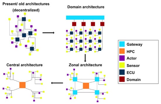
Figure 1.
Overview on E/E-architectures and evolution possibilities.
In modern planes and flight systems, centralized systems are already in use. Different systems often share one physical multiprocessing unit. This saves space and weight, as both are limited in avionics. A multiprocessing unit provides multiple cores, which enables the parallel and separated working on different tasks on one physical unit [21,22]. The separation in different cores is important to avoid an influence between the different systems. On the other hand, this could be used to define clear borders and combine several systems which need to work together. This means that several layers either work on their own, or can be connected in some parts, if needed. This approach using virtual machines and multicore ECUs can lower the number of physical ECUs in avionics as well as in vehicles [6].
Due to the constant growth in data size of in vehicle networks (IVN), the common communication systems CAN-BUS, LIN-BUS, and FlexRay probably will not be able to provide sufficient data transfer rates. Therefore, communication technologies such as Ethernet gain importance drastically [6]. Ethernet networks can handle data more than 10 Mbps [23], which makes it ideal for centralized E/E-architectures and zonal gateways, as well as data intensive domains such as ADAS. A so-called Ethernet backbone handles the communication between the different gateways and domains [23].
2.2. Functional Safety
The BMS of a HEV and especially of BEVs is an important subsystem of the powertrain. Due to its main purpose to keep the battery operating in the safe operating area (SOA), a right and reliable functionality of the BMS is indispensable. Various parts need to comply with automotive safety integrity level (ASIL) standards [24]. Further, a BMS must deliver various information to other systems, and for this reason, need to work constantly. Beside measurement sensors, a BMS communicates with important actors too, which is why some parts need to fulfill safety standards and may be planed redundant. In terms of safety, components such as the HV-contactors and pyro-fuses need to be implemented in a battery system, to make sure the battery can be connected and disconnected when needed. Even though it is not needed technically, most current EVs use two of these HV-contactors for security reasons. In terms of a malfunction of one contactor, the system can still be disconnected and brought into a safe state.
Further, safety relevant systems such as the BMS need to be protected against electromagnetic interferences (EMI), especially if they use, for example, wireless transmission. A BMS, as an important component in EVs, is ranked as an ASIL C component by the automotive industry. This means it has a high level of responsibility to work properly according to the ISO 26262. To be able to obtain exact approximations, all of the modules of a BMS have to measure the different magnitudes constantly. Losing the ability to communicate the data of one or more modules at the same time due to a damage or a malfunction (e.g., software bug) would lead to an incorrect state estimation and therefore may cause the vehicle to warn the driver or even stop the vehicle in order to prevent fatal damage. To provide a safe driving ability in such situations, at least as long as possible, a BMS should be able to work with the loss of a few measurement modules [25]. Therefore, the different measurement modules often can measure the cell voltages in different ways. If the accurate one is not working as it is supposed to, many systems still generate binary information about the actual voltage [26]. Even though this is not as accurate as in the normal state, it can be used for the most important situations and therefor help to keep the battery operate in its SOA in error conditions.
EVs need to be safe against critical currents between high voltage components and the ground. That is why the United Nations defined several isolation resistances in their 20th Global Technical Regulation [27]. Moreover, charging intervals are described to prevent the car to enable the active driving mode while it is physically plugged in into a charging station.
Together with the upcoming electrification and growing functional safety requirements of various systems such as steer-by-wire, assisted braking systems and lastly the BMS, future E/E architectures need to proceed with different failure possibilities. AUTOSAR tries to set standards in the automotive E/E-architecture sector. HPCs and centralized architectures in general can achieve a high level of ASIL if those are redundantly structured. Not only for safety reasons, but also to achieve the highest possible efficiency, a redundantly structured computing unit can deliver advantages. The redundant unit can be used for monitoring functions and handle degraded safety regarding functionalities in case of an error [28]. Hence, a redundant, centralized E/E-architecture might lead to a safer system overall, since every DCU or HPC could be mirrored or at least in some parts replaced if needed.
2.3. Battery Management Systems
A BMS aims to measure different parameters of a battery, such as cell- and module voltages or currents, as well as temperatures. In addition, the BMS calculates different quantities such as SOC, SOL, SOP and SOH [7]. Furthermore, it measures the charging and discharging current of a battery, using shunts, Hall or/and fluxgate sensors. The purpose of a BMS is to keep the battery operating in a safe, reliable and efficient way in every operating state [8]. For this, the BMS consists of different modules, actors and sensors. In general, there are three different BMS architectures in BEVs and HEVs. One of them is the centralized architecture, which collects and processes the measurements on a single module over one channel connection to each battery module. There is also a decentralized architecture, which can be separated into a modular and a distributed sub-architecture. The modular architecture consists of several slave modules and a master module, which communicates via CAN or a wireless connection. While the slave modules measure voltages, currents and temperatures at each battery module, the master module collects the overall measurements of each measurement module and processes the different states out of them. Finally, the distributed architectures are also built out of a main computing unit (master) and several measurement units (slaves). Different from the modular architecture, it has one slave for each battery cell. This is why this topology often becomes more expensive than the others [29,30,31,32]. Figure 2 shows all possible BMS architectures (centralized; decentralized) in general and for overview.
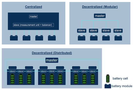
Figure 2.
BMS topologies: centralized, decentralized (modular) and decentralized (distributed).
Even though commercial BMS use master and slave solutions in a decentralized modular way, there are several architectures and ways to implement them. Besides the most common way to use one slave per battery module and connect it via daisy or ring chain to one master unit, some companies work with wireless transmitters from the slaves to the master [33] and others use one master for each battery module section (string). The master as a computing unit communicates with several systems and actors. It advises other components how to proceed with calculated and measured data. Therefore, the BMS nowadays acts as an ECU [34].
Data such as temperature and voltage are measured relatively constant to be able to calculate the different states (e.g., SOC) as well as possible; a BMS can measure these values in a time interval around 200–300 µs [35]. The amount of data which is produced and collected by the BMS does not exceed the bandwidth of the CAN communication yet. Due to that, CAN, UART, and RS232 are common communication channels inside the BMS modules as well as between the BMS and other subsystems. To avoid over-charge and over-discharge currents, the BMS communicates to the junction box and therefore switches the high voltage contactors as well as the contractor of the pre-charging circuit. The pre-charging contractor is in line with a resistor to avoid high currents at the startup of the system. Once the capacitor of the DC intermediate circuit is preloaded, the junction box closes the contractor and opens the precharging contractor. Furthermore, the BMS handles the balancing of each battery module, which is why the cell measurement units on top of the single battery cells or battery modules also may have balancing modules integrated or attached. Since manufacturers need to isolate the high voltage battery pack from the chassis and want to avoid short circuits between them, the isolation resistance must be measured and analyzed too. To do so, an iso-meter is implemented between the high-voltage lines and the ground (chassis). Figure 3 and Figure 4 illustrate exemplary current and signal diagrams of a BMS.
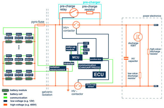
Figure 3.
Exemplary BMS-architecture with distributed master and slave units and a daisy-chain communication.
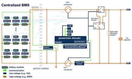
Figure 4.
Exemplary BMS-architecture with a powertrain-domain integrated master unit and a daisy-chain communication.
2.4. Further Development of E/E Architectures and Challenges in Product Development
The change from combustion engine driven vehicles to EVs lays the chance open to reduce the number of ECUs in vehicles. Not only OTA updates, but also the growing connectivity between different subsystems can only be realized by centralized E/E-architectures efficiently. Space, weight, energy consumption and costs are important parameters in the design process of vehicles. In particular, for electric vehicles, a reduction in physical ECUs makes sense, especially because software has an even greater share in these vehicles than in HEVs or vehicles powered by internal combustion engines. Together with the growing relevance of ADAS, many systems need to share information among each other. This will promote the centralization of the E/E-architecture and the combination of several subsystems into one system.
As mentioned in Section 1, avionic E/E-architectures nowadays work with multi-core processing units. According to [20,36,37] multi-core operating systems are also promising future technologies for EV E/E-architectures. It enables the efficient use of a computing unit. High-performance applications such as x-by-wire and the BMS can be implemented more easily this way. Multi-core units are able to process several tasks parallel on separate cores. This results in an efficient use of physical hardware power and reduces the loss of energy at the same time. Nevertheless, the other architectures shown in Section 1 are also promising for EVs. Many manufacturers need to transform their current decentralized systems into more centralized ones, which can be enabled by an evolutionary product development process (compare Section 5).
Coming from a decentralized architecture, a domain oriented architecture already opens up advantages such as OTA updates and the combination of related sub-ECUs into one domain. In terms of a domain-oriented E/E-architecture, there are several domains found: The powertrain or vehicle control domain, which handles functions considering the movement and energy flow in EVs, the ADAS domain for autonomous driving functions, a body and comfort domain for the interior functions, a connectivity domain that handles communication between the car and further several devices and sometimes also an infotainment domain [6,38]. A powertrain or vehicle control domain unit is indispensable in EVs due to the required connectivity between the single electric components needed for driving.
3. Design of a Distributed BMS and Common BMS Functions
This chapter describes and analyses how a BMS is designed today. Figure 3 shows a signal and circuit diagram of an exemplary BMS with distributed master and slave units including further relevant components. In addition, common functions of a BMS are described in the following as well.
In general, a BMS collects information about the present state of the battery in a car. Whether in distributed, centralized or modular architectures, its task is to let the battery operate in a safe and efficient way. To do so, it measures voltages, temperatures by its cell measurement or slave modules. Moreover, the current flowing into or out of the battery is measured. On the master unit, more precisely on its micro control unit (MCU), all the information is stored and the SOH, SOP, SOC and the SOL are calculated.
3.1. Balancing
Since not all cells are equal in their capacity, maximum voltage and charging habits (e.g., internal resistor), the energy of the modules and cells must be balanced during the charging and discharging process (known as active or passive balancing). The single battery cells should maintain the same voltage level in operation. Overcharge and large voltage differences between the single cells should be avoided. Therefore, balancing techniques are established in present systems. Either the cells can be discharged via a resistor during the charging process individually in the passive balancing strategy, or the amount of stored energy is changed between different cells in an active cell balancing strategy. The cell with the lowest charge obtains the charge from a cell or several cells with higher charge. Active balancing is more complicated to implement and also more safety-critical than passive balancing due to the need for different switches. Today’s battery cells normally do not have large differences in their parameters after production because they are sorted by measurements according to quality tranches.
3.2. HV-Contactors and Electrical Safety
Furthermore, to protect the battery system against an overcharge and over discharge current, the BMS needs to switch the high voltage (HV) contactors and therefore to communicate to the junction box of an EV. Most EVs do have two of these HV contactors, one at the HV+ and one on the HV− side of the battery pack. In addition to protect the HV-system immediately after a crash, a pyro-fuse disconnects the circuit triggered by a crash sensor. At the ignition of the system, the HV-capacitor gets charged over a in-line pre-charge resistor to avoid high inrush currents. Another circuit is there to discharge the HV-capacitor when the HV-system is shut-down. Normally, the HV-capacitor is actively discharged over a small value resistor and a transistor (IGBT). In case this system is subject to an error, there is an additional large resistor in parallel to the HV-capacitor to make sure it can be discharged in every scenario in a passive way. This is an example of an existing redundancy in the electrical circuit of a HV-system to increase its safety. If the HV-capacitor is not discharged, electrical accidents can occur when working on the HV-system due to voltages above 60 V.
4. Analysis of Centralized BMS Architectures
4.1. Design of a Centralized BMS
Through the application of a centralized processing unit in a BMS as presented in Figure 4, different aspects must be determined. There are several possible architectures to integrate the BMS, as shown in Figure 1. In the following domain vehicle control units (VCU) and powertrain domains (PD) are focused on, since those are more likely to exist in various vehicles soon. Nevertheless, all aspects of the following work can be applied for all centralized architectures. The PD includes the BMS master functionalities in a layer, without that there is a need for a distributed BMS unit. The communication between PD and the slave units is a daisy-chain. This section describes the opportunities and risks of a centralized BMS and therefore performs a virtual synthesis of such a system.
The functions and tasks of a BMS can be processed by a central PD or a VCU in a centralized architecture. A centralized computing unit such as the VCU, which is used to define the state values of the battery, could use information of other control units more easily for new features in case of the BMS. In return, the BMS could share its raw data with the other subsystems with high resolution. Therefore, the BMS might obtain access to rotation speeds of the wheels and the electric machine, GPS speed and acceleration data. Moreover, there is now access to the in-body resistance and temperature of the electric machine. This data helps to precisely predict the vehicle range. The data can be used to adopt the inverter control strategy to the inner resistor of the electric machine to avoid power differences of vehicle tranches. Furthermore, the measurement modules could participate as sensor units only and the architecture can be simplified due to this.
The single slave modules calculate the measured voltages and temperatures. Because the measurement physics need resistors to determine the values, the slave modules need to have a small control unit. In today’s conventional EV batteries with smaller cells, e.g., 21,700, and a modular design an overall sum of around 7000 cells, makes a complex slave module arrangement necessary. The upcoming cell-to-pack design with 30–40 cells enables a more centralized slave module design, see Figure 5. It is then conceivable to connect all cells of a battery with only one slave module. A direct connection to the PD is not expedient due to the then numerous cable connections through the temperature (often 4-wire measurement) and voltage measurement. With prismatic cells in a cell-to-pack design, a high level of the integration of cells, slave module and junction box is possible. For this reason, the design saves installation space or enables high ranges through better utilization of space and thus a high energy density of the battery. The junction box contains components that are sensibly located in the immediate vicinity of the HV-lines of the battery in order to avoid electrical hazards. The positioning of the slave module is more flexible. The BMS’s computing unit can be put on one controlling unit (e.g., PD), where the different measurements of the slave modules are post processed.
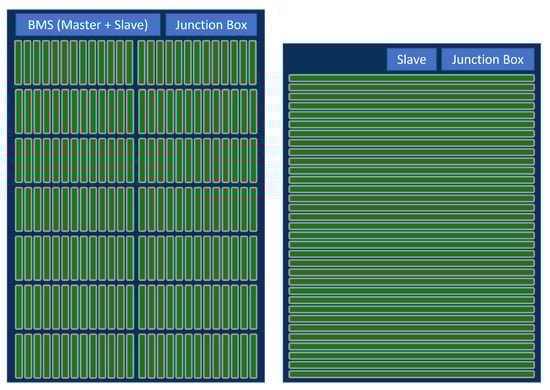
Figure 5.
Scale representation of a 400 V battery with prismatic cells and a capacity of about 60 kWh in conventional design (left) and cell-to-pack design (right).
4.2. Wireless Communication
A few manufacturers manage the communication traffic between the master and the slave units wirelessly, which benefits in less cables between each unit and an easier malfunction detection of the single modules. However, this design requires further transmitter modules and needs to be safe against the electromagnetic interference of third players in the EV environment as well as against access from the outside by persons or malware. None the less, through a certain point, wireless communication inside an BMS could lead to many benefits. A wireless communication enables the ability to share parameters to systems beyond the vehicle, such as mobile devices, charging stations, solar roofs and smart home systems. In addition, the BMS and the home storage systems demand energy and work either as an rechargeable energy storage system (RESS) or as a buffer in times where less electrical energy is used than produced. Communication between the battery and the charging station can enable new efficient or battery life-saving charging strategies. Moreover, third party systems, such as security systems, can take advantage of a wireless transmission of BMS data.
4.3. Common and Additional BMS Functions
Accordingly, the Master unit of the BMS calculates states such as the SOC. This exercise can be fulfilled by using various approaches. In Lithium-Ion battery cell systems, the SOC can be estimated by the cell voltage measurements, due to the drop of the cell voltage over the discharging process. Many modern BMS’s need to be more precise to obtain exact state calculations and therefore use methods such as the coulomb counting. Using this technique, the in-rushing as well as the out-rushing current becomes integrated over time to receive the actual capacity of the battery. The coulomb counting requires at least one precise current sensor in the HV-line. As shown in [8], there are multiple other estimation methods for the SOC with different accuracies and difficulty levels of implementation. Depending on the method, intensive calculation processes are needed. Being able to calculate the states on a high-performance computing unit or a powerful domain is helpful at this point. Similarly, the states of the BMS can be combined with additional information to achieve exact vehicle range prediction and health analyses of the battery cells. Velocities, accelerations, geographical topology data, environmental temperatures and other data can be collected on the PD and used for calculations.
In addition, not only the BMS functions might benefit from a central computing unit. Since effective techniques of firefighting burning EVs is still limited, an early prediction about critical thermal states is essential. In order to prevent a fire in the battery and therefore in public or private places, a communication to third parties such as central fire detection systems and the BMS is helpful. Such systems can alarm responsible persons by giving them important information about critical states and the precise position of the vehicle. The implementation of such features might refer to a sub-unit, where the BMS could process and send information in an offline mode without the need to start-up the whole centralized computing unit (e.g., PD). Danger is usually large while charging a BEV. The central computer or parts of it must be online while charging because the BMS and charger need to communicate. Sending data is possible without any problems so that temperatures, voltages, currents and other important states such as the SOC can be sent via a wireless communication system.
The battery junction box is often integrated into the battery box and also connected to the BMS directly. Another approach by centralizing different systems such as the BMS on one specific unit could be made by putting the junction box and the BMS together into the power electronics box. The whole PD hardware and functionality could be located in that box, which is located close to the battery cells. The main function of the power electronics today is to turn the DC current, which is coming from the battery into AC current to supply the electric motor with power. For recuperation, the process can be inverted and the battery is then supplied with power. It also changes the frequency of AC currents and needs to convert DC voltages up and down. Overall, the power electronic controls the energy flows and is therefore instrumental in the safe operation of the vehicle. Therefore, it makes sense that the power electronics also have access to the main parts of the battery when needed. Beside charging, AC/DC-conversion, and DC/DC-conversion, also parts of the junction box and the master unit of the BMS, could be implemented in the PD box. HV-contactors and fuses in the power electronics prevent the battery from further electrical faults directly. Thermal problems can arise along the HV-lines if those components are located wrong. These components need to remain in proximity to the battery cells.
Since the merging of components into a central E/E architecture offers many opportunities on the one hand, but is also very complex and fraught with risk on the other, a methodical proceeding is explained, which makes chances visible in an early development stage and at the same time minimizes development risks. A powerful example illustrating the potential that can be raised by a more centralized system concludes the scientific section of this paper.
5. Methodical Approach to the Synthesis of BMS Architectures
An E/E-architecture of an automotive BMS should be appropriate for current and future battery technologies, as many engineers and scientists expect technological changes within the next years. Possible battery technologies that are currently on the market are Lithium-ion batteries and on Nickel-metal-hydride batteries [39]. In the next few years, solid-state batteries will most probably follow [40]. Battery design will also move more and more toward highly integrated weight- and volume-optimized approaches, as described in Figure 5, using the cell-to-pack as an example. It is therefore sensible to base the synthesis of the architecture of future automotive BMSs on certain assumptions and functional requirements, which will most probably not change within the next two decades.
Taking the considerations listed above, the following assumptions concerning the synthesis of the prospective BMS can be formulated:
- The vehicle battery consists of individual cells, which are connected in series or parallel in order to provide the desired capacity and voltage level as well as charge and discharge current.
- The vehicle battery may consist of sub-modules, which also consists of individual cells, which are connected in series or parallel in order to provide the desired capacity, voltage level and discharge current. The cause for these sub-modules can be geometrical (divided spaces in the vehicle for battery sub-modules), functional (e.g. redundant sub-modules) or caused by assembly considerations (e.g., sub-modules with lower voltage, which are less dangerous).
- The BMS must provide protection devices for disconnecting the mains (e.g., contactors, pyro-fuse) and protection against high currents (e.g., fuses, pre-charge resistor).
- The measurement of voltage, current and temperature is important, because the cells need to be operated in the safe operating area.
- The BMS may also be responsible for an active regulation of the temperature of the vehicle battery; usually both a regulation of heating and cooling entities is necessary.
The synthesis of E/E-architectures needs to be integrated in the overall product development processes. In the automotive industry, currently the model-based systems engineering (MBSE) [41] is employed for achieving efficient digital processes with connected product and process models [42]. The processes constitute the development life-cycle of the technical system and are usually represented in the form of a V-model—such models are, for instance, described in the guideline VDI/VDE 2206 [43]. The V-model is a graphical representation of the logical sequence of process steps [44]. Several essential elements in this sequence concern the functional domain (compare [45,46], i.e., models of the technical system, which describe the intended functionality. The functional domain is located on the upper left side of the V (Figure 6—based on the guideline VDI/VDE 2206 [43]).
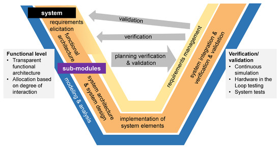
Figure 6.
V-model including synthesis process steps.
One of the cornerstones of successful product development is a transparent representation and a conscious occupation with the functional domain, which requires an integrated consideration [45]. Very important are also verification and validation processes. It is important to note that both verification, i.e., evaluating whether the BMS meets the given requirements, and validation, i.e., evaluating whether the requirements correctly and entirely captures the customer’s expectations, are essential. An important role in verification processes plays so-called HiL testing, i.e., a combination of real and virtual components in a simulation. Such verification processes should be conducted continuously—this leads together with complete system tests to an evolutionary development process (compare Section 2.4).
As stated above, the clarification and conscious development of the functional domain may be crucial. From the considerations in the earlier sections, a consolidated list of the main functions of the BMS can be generated:
- Safely start-up and shut down the system (in normal operation or in case of a major error e.g., a crash),
- Measure the voltage of each individual cell,
- measure the discharge and charge current of the individual cells, of sub-modules and/or of the whole vehicle battery,
- measure the temperature at certain points of the battery,
- estimate the state of charge (SoC) of the individual cells, of sub-modules and/or of the whole vehicle battery,
- estimate the state of health (SoH) of the individual cells, of sub-modules and/or of the whole vehicle battery,
- balance the charging voltage resp. current of the individual cells and of sub-modules,
- balance the discharging voltage resp. current of the individual cells and of sub-modules,
- protect the cells from overheating,
- prepare the cells for high-speed charging or discharging and
- communicate with the drive train and the human machine interface (HMI).
Additional functions would be the estimations of the state of life (SoF) and the state of available power (SoP) as well as a protection of over- and under voltage and the early prediction of thermal runaways. Figure 7 presents the main functions, which were analyzed concerning their mutual interaction in the form of a function interaction matrix.
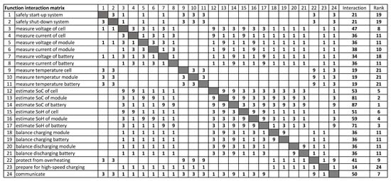
Figure 7.
Function interaction matrix.
This matrix displays the interactions, allows to identify functions with a high level of interaction and thus increases the transparency of functional interaction. The core synthesis of E/E-architectures can be carried out by means of topology optimization algorithms; this topology optimization requires an abstract model of these architectures and appropriate optimization criteria. One possibility is described by Shan and Chen [47], who employ an optimization function, which is based on the design structure matrix and axiomatic design theory. Similar approaches employ product function matrices [48] as well as a combination of the Multi-Domain Matrix (MDM) and functional models [49]. It is also possible to create these possibilities manually, keeping in mind the requirements, the BMS functions and the functional relationships. An evaluation of these possibilities can be based on a diagram, as shown in Figure 8.
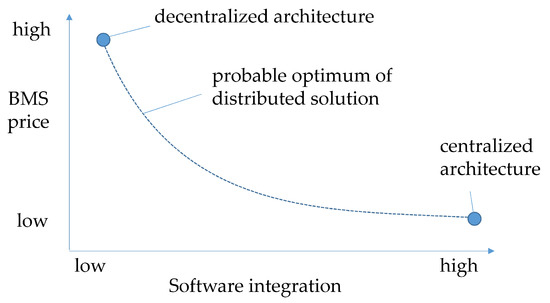
Figure 8.
Evaluation of E/E-architectures.
Visible in Figure 8 are the two ends of the solution continuum. One is a completely centralized solution, with only one central processing unit and all sensors directly connected to the central processing unit. The other end is a completely decentralised solution, within which all sensors are connected to slave units in the direct surroundings and all processing is conducted by a large network of slaves; a central processing unit does not even exist. The synthesized solutions will be a compromise between these extremes, and the best of them will probably achieve characteristics that are on the line of the probable optimum, as visible in Figure 8. It can be concluded that a centralised solution is desirable for, amongst others, economic reasons. A centralised E/E-architecture of the BMS can only be sensibly achieved if both hardware and software functions are realised in central entities. This kind of software integration will pose additional challenges on the product development process and will require a methodological procedure style according to the V-model and continuous simulation and HiL-tests (see also Figure 6).
Obviously, a holistic evaluation has to consider a large number of further criteria, which mainly result from the requirements collected in the early phases of the architecture development process (compare Figure 6) and managed throughout the process [50]. Important evaluation criteria range from communication and update possibilities, over diagnosis possibilities to the capability to accommodate faults [51]. Many standards, e.g., ISO/IEC 12207, ISO/IEC 15504, ISO/IEC 25010 and ISO 26262 strongly influence the product development of mechatronic system in the automotive industry; they both are a source for additional requirements and offer methods to assure the fulfillment of these requirements [52]. The considerations will go beyond the functional domain and will also concern the abstract and concrete physics [53]. In most cases, this will be an iterative synthesis process leading to a solution, which is the best compromise concerning all these criteria. The inherent logic of this process can be understood as several runs through the V-model (Figure 6), i.e., the engineers will review the requirements, the functional architecture and the system architecture again and again in order to achieve an optimised system.
6. Exemplary Synthesis of a Powertrain Domain Focusing Start-Up and Shut-Down of the HV-System
A central PD architecture allows software function as well as physical components to be integrated at a higher level. Accordingly, for a cost-efficient system synthesis, the functions as well as the hardware components of the system must be analyzed in detail, as shown in Section 5. Simulations followed by step-by-step detailing by incorporating hardware components has proven to be a highly cost and resource efficient development method [54]. The underlying evolutionary development process is shown in Figure 9.
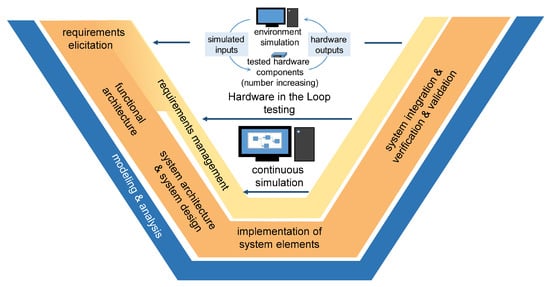
Figure 9.
Evolutionary development process for BMS architecture.
This chapter exemplifies parts of the synthesis process. It focuses on a PD architecture and the safe start-up or shut-down of the HV-system. The synthesis presented focuses on the pre-evaluation and feasibility of novel central architectures. Possible ways for hardware integration in HiL systems are presented in the outlook of this paper for a complete overview.
First, a functional analysis needs to be carried out to make the advantages of a centralized architecture visible. In a next step, the feasibility of the newly developed system is verified via automated simulations.
6.1. Detailed Function and Interaction Analysis
In today’s batteries there are three main contactors in the BMS that are needed to operate the battery safely and to connect or disconnect the HV-system, as shown in Figure 4. Another contactor is located in the power electronics to actively discharge the HV-capacitor when shutting down the HV-system.
The basic function of all contactors is to safely connect and disconnect electrical circuits. The HV-contactors are electromechanical switches located in the BMS’s junction box in a distributed system. They need to switch under high voltages or currents safely and with a high number of duty cycles. Due to arcs, which do occur while the contactors are connecting or disconnecting the circuit, the component lifetime is limited. To minimize the risk of damage by arcs, the contactors often become vacuumed and overmolded. The main switches of the HV-system can be loaded with high currents for a long time because these are connected under normal operation (vehicle is driving). Full galvanic isolation at least in two points (redundancy) is an important safety criterion in HV-systems today.
The third contactor in the BMS is the switch of the precharging resistor. This switch is only briefly loaded with higher currents when the system is starting up until the DC-capacitor in the power electronics has reached a sufficient SOC. When the system is shut-down, the DC-capacitor must be discharged in a short time (seconds) to avoid electrical accidents.
A low-value resistor is connected via another contactor in the power electronics. Here, higher currents are transmitted for a short time. The high-value passive resistor in parallel to the DC-capacitor is permanently connected and serves as a redundancy. It can discharge the capacitor over a longer period (up to minutes) in the event of a fault in the low-value resistors circuit.
In a sum, this is why contactors and resistors are relevant parts in the design process of a centralized PD in terms of their function, price, size and also weight.
A detailed function and interaction analysis demonstrates that by integrating components and functions into a central architecture, potential savings can be made in starting up as well as in shutting down the HV-system. However, a component that is suitable for both operations must be designed as a compromise. In order to check the feasibility, simulations are set up, which can also be used for the HiL test process later. For this reason, simulations should be performed on real-time capable systems.
In this example, the pre-charge resistor is integrated into the power electronics DC-link to achieve a reduction in costs and overall building size of a centralized powertrain system. The in-rushing current into the HV-system while starting up the battery system is limited by the pre-charge resistor. Whereas the electromechanical contactors are physically disconnected once they are open, semiconductors either need a further small physical switch or a physical gap, in order to ensure a safe disjuncture. To do so, the current in the pre-charge circuit needs to be limited to a value, where it is safe to operate for the semiconductor. The current systems that are available on the market today mostly use electromechanical contactors and passive pre-charge resistors with values between 1–1000 Ω [55,56]. Depending on the powertrain’s voltage level, these values may be higher in some pre-charge circuits. Furthermore, current systems provide two different discharge resistors, which are connected in parallel to the DC-capacitor. To make sure the capacitor becomes quick and fully discharged after a system shut-down, two different discharge resistors are connected in parallel to the capacitor.
One possible simplification is to use one small valued resistor as a pre-charge and as an active discharge resistor. It needs to be switched in series or in parallel in the DC-circuit, depending on the operation mode. In general, there are various schematics to realize such an electrical circuit, as shown in Figure 10, Figure 11 and Figure 12. In the following, those three systems are presented in detail. All schematics allow one to pre-charge and active discharge the HV-capacitor with a single resistor (resistor 1). Further, the voltage drop at the two main contactors (HV+ contactor and HV− contactor) is measured at the positions K1, K2, K3 and K4. With this setup, the states of the HV+ contactor and the HV− contactor can be observed and determined. Therefore, a cross-measurement (CM) module is included in the upcoming Figures.
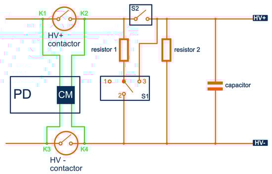
Figure 10.
Four switches/contactors and two resistors (4S2R) setup.
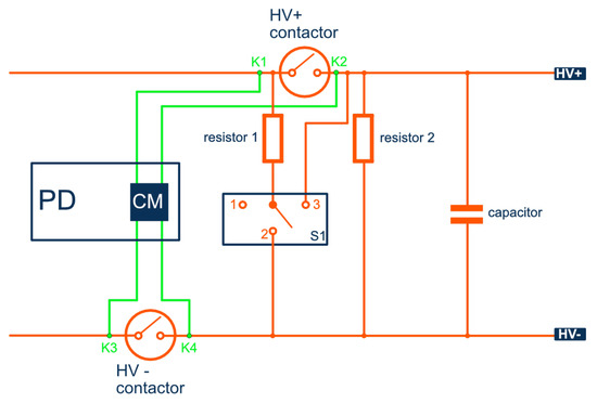
Figure 11.
Three switches/contactors and two resistors (3S2R1) setup.
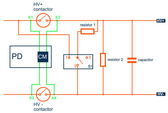
Figure 12.
Three switches/contactors and two resistors (3S2R2) setup.
Figure 10 shows four switches and two resistors (4S2R) setup. Resistor 1 is the pre- and discharge resistor. Resistor 2 is a high value discharge resistor and switch 1 shifts resistor 1 from a series to a parallel connection. In state 1, the resistor is disconnected. Switch 2 is bridging resistor 1 under operation.
The second schematic in Figure 11 is the first of two schematics, which only consists of three switches and two resistors (3S2R1). The resistor function is the same as in the presented 4S2R system. Moreover, switch 1 has the same function as in the 4S2R system. The HV+ contactor is now also bridging resistor 1 under operation.
The third schematic is slightly different compared to the second (3S2R1) and is presented in Figure 12. In comparison to the 3S2R1-system, this 3S2R2-system is able to actively discharge the capacitor without the need to close the HV+ contactor.
The switch S1 must face the same requirements regarding safety and service life as the main contactors (HV+ and HV−) of the HV-system. It is discussed to use semiconductor switches such as IGBTs, super-junction or silicon carbide (SiC) MOSFETs for those contactors already [57,58]. Using semiconductors, the problem of arousing arcs no longer exists, since semiconductors do not switch in a mechanical way. This leads to a reduction of size and more service life. However, no galvanic isolation can be provided, on the other hand.
The next Section 6.2 presents possible failure modes based on simulation results. Those real-time simulations are carried out with a Typhoon HiL system. To verify the simulation models, a first calculation helps, which is presented in the following. The presented equations are also used for the design of the relevant components.
This example assumes a 400 V battery system. A DC-capacitor charging time of 1.5 s should be achieved. The DC-capacitor has a capacity of 400 μF. The charge and discharge time is calculated with the help of the time constant , the resistance R and the capacity C.
It is assumed that the capacitor is almost charged after a time of . This results in Equation (2) and a resistance of for resistor 1.
The maximum current in this example is also dependent from the battery voltage .
In addition, the present current while starting-up the system can be calculated as a function of time t.
The influence of the second high-value resistor connected in parallel is neglected in these calculations. This is taken into account in the simulation, which is why the values differ slightly from the first design. Figure 13 shows the schematic of the simulation of the 3S2R2 system. In the schematic, represents the high-value resistor and represents resistor 1. Since Typhoon HiL does not provide multiple-state-switches yet, two switches (S1 and S2) are used to simulate S1 from Figure 12.
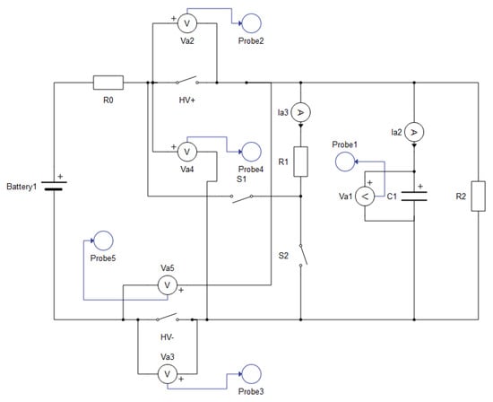
Figure 13.
Schematic of the 3S2R2 system in the Typhoon HiL schematic editor.
Figure 14 shows the current and the voltage for capacitor of 3S2R2 as a function of time (scale of x-axis: ). The circuit in this example is equivalent to the circuit presented in Figure 14. Because all three systems use the same parameters, the current and voltage plots for the 4S2R and 3S2R1 systems are identical. After 1 second S1 is switched into position 1 in the simulation. Presently, the capacitor gets charged through resistor 1. After 1.5 divisions (1.5 s) the capacitor is almost fully charged (99%). In the left graph, the low current of maximal 0.5–0.6 A can be observed. At a simulation time of around 4 s, S1 is opened and S2 is closed (see Figure 13). Therefore, C1 gets discharged through R1 and the voltage drops from 432.5 V to 0 V in 1.5 seconds with a minimum current of almost A (due to the parallel connection of R1 and R2). The voltage of 432.5 V results from the battery model and is the maximal voltage with a SOC of 100 %. The nominal voltage parameter is set to 400 V.
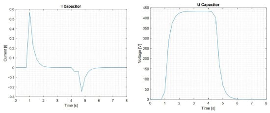
Figure 14.
Current (left) and voltage (right) at the capacitor , with start up and active discharge of the HV-system of the 3S2R2 topology as a function of time.
Figure 15 shows a shut-down operation using resistor 2. In this case, the simulation was created so that switch S2 cannot be operated. In the real system, a defective resistor R1 could also cause such an error. This creates an error in the active discharge path, so that it cant be used. The diagrams show the time course with 1 . For the simulations, the capacity of the HV-capacitor is 400 μF, resistor 1 has 750 Ω and resistor 2 is at 10,000 Ω.
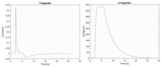
Figure 15.
Current (left) and voltage (right) at the capacitor , with start up while start-up and passive discharge of the HV-system of the 3S2R2 topology as a function of time.
Presently, the shut-down process takes longer than using resistor 1 in the active discharge path.
The capacitor is discharged (99%) after s, as shown in Figure 15. Due to the high value of resistor 2, the system current is low and decreases relatively fast (second 6 to second 26).
The fault case demonstrated is a “standard fault case” in today’s HV-systems. Usually all HV-systems have a passive and an active discharge path included in the power electronics. In the following chapter, particular attention will be paid to the new structures. Especially with regard to possible fault cases, disadvantages and advantages. Simulation models were used throughout for the evaluation.
6.2. Failure Modes and Comparison of the Presented Topologies
In order to consider all faults systematically, the number of switching states must first be known. All three topologies (Figure 10, Figure 11 and Figure 12) can have different switching-states in theory, where n is the number of switches. S1 has three switching states but only one state can be active. This is why 24 different switching-states remain for the 4S2R topology instead of 64.
The 24 different states of the 4S2R topology are listed in Table 1. The table describes the different switching states and the corresponding voltage and current measurements. HV+ and HV− stands for the voltage drop over the HV+ or HV− contactor. K1/K4 and K2/K3 describes the potential difference between measurement point K1 and K4 or K2 and K3. This measurement-method is described as cross measurement CM in this paper. The abbreviation “n.d.” stands for a not defined state, which can be neglected. Since the simulations of the different states were taken separately, and the SoC of the battery was refreshed for each simulation, the voltage-measurement-values are equal in every cycle.

Table 1.
Twenty-four states of the system 4S2R.
The 4S2R topology shows two critical (red lined) states. These failure modes occur if resistor 1 is switched in parallel (position 2) to the HV-battery, while the HV+ and the HV− contactor is closed. In this case, the HV-battery is discharged through the low-value resistor 1. The current is relatively low with 0.6 A, but constant. Resistor 1 can stand such currents over a short time period. The typical constant power limit of around 50 W is exceeded in this state by a factor of more than five. This state may cause a destruction of resistor 1 after a certain time period. To prevent the system from such a critical state, one of the HV-contactors must disconnect the circuit. This includes that the switching states must be known by the system. With the state-of-the-art CM alone, the critical state cannot be detected.
Table 2 shows the different switching states according to the 3S2R1 topology from Figure 11. The 3S2R1 system shows the same critical states as the 4S2R system when both HV-contactors are closed and the S1 is in switching position 2. If S1 is in state 2 and the HV−contactor is closed, the failure still occurs in this system, although the HV+ contactor is open. For this reason, it must be avoided that HV− gets closed whenever S1 is in switching state 2. If the HV− contactor cannot be opened, the error cannot be fixed.
Table 2.
Twelve states of the system 3S2R1.
Table 3 shows the different switching states of the 3S2R2 topology from Figure 12. The 3S2R2 circuit shows only one switching state that is critical if both HV-contactors are closed and S1 is in state 2. A constant current of 0.6 A floods resistor 1.
Table 3.
Twelve states of the system 3S2R2.
In terms of the critical discharge states, the 3S2R2 schematic is the best of all three, since it only has one critical switching state. This state can be observed and prevented by opening one of the HV-contactors. Further, only three instead of four switches are used in that system. This reduces the complexity of the system and lowers the number of possible failing components. Less switches need to be provided, observed and controlled. In addtion, the same resistor could be used for pre- and discharging the HV capacitor. In the example calculation and simulation above, the 750 Ω resistor would lead to a maximal current of 0.6 A. Nevertheless, the 4S3R-schematic comes with the ability to disconnect the system even in the case when the HV+ contactor can not be opened. This results in maximal safety. The detection of the switching states of the two inline contactors HV+ and S1 is challenging in that system. Table 4 shows the advantages and disadvantages of the three topologies mentioned above in the form of a small comparison.
Table 4.
Overview about the advantages of the three topologies.
7. Conclusions, Summary and Outlook
This paper presents possible centralized E/E-architectures for BEVs and the implementation of the BMS into those topologies. The upcoming benefits as well as possible drawbacks are discussed. With a high integration level, new functions can be implemented and components such as the discharge resistor can be replaced by other existing components. Nevertheless, some functions such as the SOC estimation need to work even if the vehicle is parked and needs to be planed redundant at some point on a separate ECU or an independent computing unit. Centralization of the BMS must be aligned with the E/E-architecture of the vehicle. Besides the possible reduction in hardware components and wiring, the BMS becomes less complex, easily scalable and the most power consuming functions are located on high-performance computing units. This results in a more energy efficient E/E-architecture. Overall, a centralized BMS master unit, combined with a centralized E/E-architecture, could lead to various advantages and options in terms of safety, reliability, and quality of the output functions.
The transformation to a more and more software-driven vehicle through this centralization requires the consistent use of a systematic product development. A possible approach is presented on the basis of an extended V-model. A key element, especially in the area of the BMS, is the consistent use of simulation tools. Thus, critical conditions can be identified and eliminated at an early stage of product development. Later, these simulation models can be used to test the software in embedded systems or on high-performance computers. For this reason, it is essential to ensure that the simulation models are based on real-time capable systems. This accelerates development times and prevents errors.
As an example, the analysis of three new electric topologies integrating parts of the BMS into today’s power electronics is presented. These considerations are necessary to enable the centralization of the E/E architecture in a PD. The developed topologies have been simulated in a real-time capable system and then analyzed for advantages, disadvantages and possible errors. Therefore, the 3S2R2 topology is identified to be attractive in a highly integrated PD. The topology results in more safety by using less components at the same time and safes money and space in modern BMS production for EVs. In a next step, concepts, such as those, need to be tested in HiL setups with the simulation models already created, according to the presented V-model. Figure 16 shows a possible controller hardware-in-the-loop (cHiL) architecture of a BMS, in which relevant software could be tested. A battery emulator is necessary for this purpose in order to be able to test the most critical conditions, while there are errors in the battery. With such a setup, not only the short-circuit of the battery via the low-value discharge resistor could be tested. The software can also be tested for short-circuits in cells, overvoltage or undervoltage as well as borderline temperatures. Moreover, multiple error states can be tested.
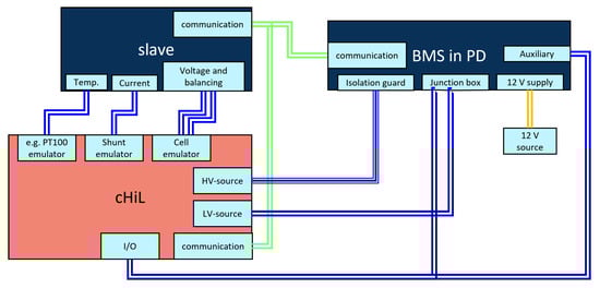
Figure 16.
Possible cHiL architecture of a BMS.
This paper focuses on the analysis of possibilities and approaches for the synthesis of appropriate architectures for automotive BMSs. Aspects such as functions, interactions and failure modes are analyzed. Further research should focus on HiL architectures and include further aspects, such as the economic and logistics aspects, vehicle platforms and future battery technologies. Additionally, research should address measurements of different balancing circuits; this could lead to a comparison and evaluation of the efforts and benefits of active cell balancing. It would also be interesting to research the possibilities of including fuel cell data in BMS systems for fuel cell electric vehicles (FCEVs) in order to allow a further centralization of powertrain monitoring systems. In this context, the topic of HiL-simulations may also be interesting. Finally, fruitful research may also concern software integration possibilities in centralized BMS systems.
Author Contributions
Conceptualization, L.S., B.R., M.P. and R.S.; methodology, L.S., B.R., M.P. and R.S.; original draft preparation, L.S., B.R., M.P. and R.S.; writing—review and editing, L.S., B.R., M.P. and R.S. All authors have read and agreed to the published version of the manuscript.
Funding
This research received no external funding.
Institutional Review Board Statement
Not applicable.
Informed Consent Statement
Not applicable.
Data Availability Statement
Not applicable.
Acknowledgments
The authors thank the staff of the Ravensburg-Weingarten University (RWU) for the support.
Conflicts of Interest
The authors declare no conflict of interest.
Sample Availability
Not applicable.
Abbreviations
The following abbreviations are used in this manuscript:
| ABS | Anti-lock braking system |
| ADAS | Advanced Driver Assistant Systems |
| ASIL | Automotiv Safety Integrity Level |
| BEV | Battery Electric Vehicle |
| BMS | Battery Management System |
| CHIL | Controller Hardware-in-the-Loop |
| CM | Cross-measurement |
| DCU | Domain computing unit |
| E/E | Electrical and electronic |
| ECU | Electric control unit |
| EMI | Electro magnetic Interferences |
| FCEV | Fuel Cell Electric Vehicle |
| HEV | Hybrid Electric Vehicle |
| HIL | Hardware-in-the-Loop |
| HPC | High performance computer |
| HV | High voltage |
| HV+ | Positive high voltage |
| HV− | Negative high voltage |
| IVN | In vehicle networks |
| MCU | Micro control unit |
| OTA | Over the air |
| PD | Powertrain Domain |
| RESS | Rechargeable energy storage system |
| SOA | Safe operating area |
| SOC | State of charge |
| SOH | State of health |
| SOL | State of life |
| SOP | State of available power |
| 3S2R | 3 switches/contactors and 2 resistors |
| 4S2R | 4 switches/contactors and 2 resistors |
References
- Autoweek. Available online: https://www.autoweek.com/news/green-cars/a37102623/new-mercedes-platforms-will-be-ev-only-from-2025/ (accessed on 30 May 2022).
- CNET. Available online: https://www.cnet.com/roadshow/news/volkswagen-all-electric-ev-europe-us/ (accessed on 30 May 2022).
- Forbes. Available online: https://www.forbes.com/sites/michaeltaylor/2021/02/17/ford-europe-commits-to-ev-only-future-first-car-due-in-2023/ (accessed on 30 May 2022).
- Volkswagen’s MEB Platform Underpins a New Generation of Electric Cars (CNET). Available online: https://www.cnet.com/roadshow/news/volkswagen-meb-electric-car-platform/ (accessed on 31 May 2022).
- Mercedes-Benz Announces Two Dedicated EV Platforms: EVA And MMA. Available online: https://insideevs.com/news/447621/mercedes-benz-dedicated-ev-platforms-eva-mma/ (accessed on 31 May 2022).
- Bandur, V.; Selim, G.; Pantelic, V.; Lawford, M. Making the case for centralized automotive E/E architectures. IEEE Trans. Veh. Technol. 2021, 70, 1230–1245. [Google Scholar] [CrossRef]
- Xing, Y.; Ma, E.W.; Tsui, K.L.; Pecht, M. Battery management systems in electric and hybrid vehicles. Energies 2011, 4, 1840–1857. [Google Scholar] [CrossRef]
- Ali, M.U.; Zafar, A.; Nengroo, S.H.; Hussain, S.; Junaid Alvi, M.; Kim, H.J. Towards a smarter battery management system for electric vehicle applications: A critical review of lithium-ion battery state of charge estimation. Energies 2019, 12, 446. [Google Scholar] [CrossRef]
- DriveBattery2015: “Intelligente Steuerungs- und Verschaltungskonzepte Für Modulare Elektrofahrzeug-Batteriesysteme Zur Steigerung der Effizienz und Sicherheit Sowie Zur Senkung der Systemkosten”: Abschlussbericht des Verbundvorhabens: Laufzeit des Vorhabens: 01.08.2013–30.04.2015. Available online: https://www.tib.eu/suchen/id/TIBKAT:862982553/ (accessed on 31 May 2022).
- Aktas, A. Design and implementation of adaptive battery charging method considering the battery temperature. IET Circuits Devices Syst. 2019, 14, 72–79. [Google Scholar] [CrossRef]
- Bozdal, M.; Samie, M.; Aslam, S.; Jennions, I. Evaluation of CAN Bus Security Challenges. Sensors 2020, 20, 2364. [Google Scholar] [CrossRef]
- Ernst, J.M.; Michaels, A.J. LIN bus security analysis. In Proceedings of the IECON 2018-44th Annual Conference of the IEEE Industrial Electronics Society, Washington, DC, USA, 21–23 October 2018; pp. 2085–2090. [Google Scholar]
- Park, I.; Sunwoo, M. FlexRay network parameter optimization method for automotive applications. IEEE Trans. Ind. Electron. 2010, 58, 1449–1459. [Google Scholar] [CrossRef]
- Performance to Power the Future (Bosch). Available online: https://www.bosch-mobility-solutions.com/en/mobility-topics/vehicle-computer/ (accessed on 31 May 2022).
- Continental. Available online: https://www.continental.com/en/press/press-releases/volkswagen-id3/ (accessed on 30 May 2022).
- Tesla Hardware 3 (Full Self-Driving Computer) Detailed (Autopilot Review). Available online: https://www.autopilotreview.com/tesla-custom-ai-chips-hardware-3/ (accessed on 31 May 2022).
- Haas, W.; Langjahr, P. Cross-domain vehicle control units in modern e/e architectures. In Proceedings of the 16th Internationales Stuttgarter Symposium, Stuttgarter, Germany, 15–16 March 2016; Springer: Berlin/Heidelberg, Germany, 2016; pp. 1619–1627. [Google Scholar]
- Reinhardt, D.; Kucera, M. Domain controlled architecture. In Proceedings of the Third International Conference on Pervasive and Embedded Computing and Communication Systems, Barcelona, Spain, 19–21 February 2013. [Google Scholar]
- Jiang, S. Vehicle e/e architecture and its adaptation to new technical trends (No. 2019-01-0862). In SAE Technical Paper; SAE International: Warrendale, PA, USA, 2 April 2019. [Google Scholar]
- Askaripoor, H.; Hashemi Farzaneh, M.; Knoll, A. E/E Architecture Synthesis: Challenges and Technologies. Electronics 2022, 11, 518. [Google Scholar] [CrossRef]
- All Electronics. Available online: https://www.all-electronics.de/markt/architekturen-aus-der-avionik-im-auto-wiederverwenden.html (accessed on 10 June 2022).
- Vector. Available online: https://www.vector.com/at/de/news/news/testen-unter-zeitdruck-flexible-pruefstaende-fuer-avionik-systeme-1/ (accessed on 10 June 2022).
- Steinbach, T. Ethernet-Basierte Fahrzeugnetzwerkarchitekturen für zukünftige Echtzeitsysteme im Automobil; Springer: Wiesbaden, Germany, 2018. [Google Scholar]
- EVERLASTING. D6.1—Analysis of the State of the Art on BMS. Available online: https://everlasting-project.eu/2017/03/ (accessed on 10 June 2022).
- Tatman, D. Functional Safety Considerations in Battery Management for Vehicle Electrification; Texas Instruments: Dallas, TX, USA, 2020. [Google Scholar]
- Lelie, M.; Braun, T.; Knips, M.; Nordmann, H.; Ringbeck, F.; Zappen, H.; Sauer, D.U. Battery Management System Hardware Concepts: An Overview. Appl. Sci. 2018, 8, 534. [Google Scholar] [CrossRef]
- Global Registry. Addendum 20: Global Technical Regulation No. 20. Available online: https://unece.org/transport/standards/transport/vehicle-regulations-wp29/global-technical-regulations-gtrs (accessed on 10 June 2022).
- Zimmer, B.; Oertel, M. E/E Architectures with AUTOSAR Adaptive: More Performance, Please! ATZ Elektronik 2019, 5, 1–5. [Google Scholar]
- Messier, P.; LeBel, F.-A.; Rouleau, J.; Trovao, J.P.F. Multi-Cell Emulation for Battery Management System Validation. IEEE Veh. Power Propuls. Conf. 2018, 10, 1109. [Google Scholar]
- Dai, H.; Jiang, B.; Hu, X.; Lin, X.; Wei, X.; Pecht, M. Advanced battery management strategies for a sustainable energy future: Multilayer design concepts and research trends. Renew. Sustain. Energy Rev. 2020, 10, 1016. [Google Scholar] [CrossRef]
- Designing a BMS (Battery Management System) for a Stationary Battery Storage Solution. Available online: https://www.integrasources.com/blog/bms-battery-management-system-battery-storage-solution/ (accessed on 31 May 2022).
- Instructables. Available online: https://www.instructables.com/Battery-Management-System-Introduction-to-Hardware/ (accessed on 10 June 2022).
- Texas Instruments. Available online: https://www.analog.com/en/about-adi/news-room/press-releases/2020/adi-introduces-automotive-industry-first-wireless-battery-management-system-electric-vehicles.html (accessed on 10 June 2022).
- Santeramo, A. Test of Automotive Boards. Master’s Thesis, Politecnico di Torino, Turin, Italy, 2019. [Google Scholar]
- Analog Devices. Available online: https://www.analog.com/en/technical-articles/maximizing-cell-monitoring-accuracy-data-integrity-bms.html/ (accessed on 10 June 2022).
- Lukasiewycz, M.; Steinhorst, S.; Sagstetter, F.; Chang, W.; Waszecki, P.; Kauer, M.; Chakraborty, S. Cyber-physical systems design for electric vehicles. In Proceedings of the 2012 15th Euromicro Conference on Digital System Design (IEEE), Cesme, Izmir, Turkey, 5–8 September 2012; pp. 477–484. [Google Scholar]
- Lukasiewycz, M.; Steinhorst, S.; Andalam, S.; Sagstetter, F.; Waszecki, P.; Chang, W.; Kauer, M.; Mundhenk, P.; Shanker, S.; Fahmy, S.A.; et al. System architecture and software design for electric vehicles. In Proceedings of the 50th Annual Design Automation Conference, Austin, TX, USA, 29 May–7 June 2013; pp. 1–6. [Google Scholar]
- Butzkamm, C.; Brand, K. Performancebetrachtung innerhalb einer serviceorientierten E/E-Architektur. ATZextra 2019, 24, 28–33. [Google Scholar] [CrossRef]
- Sanguesa, J.A.; Torres-Sanz, V.; Garrido, P.; Martinez, F.J.; Marquez-Barja, J.M. A Review on Electric Vehicles: Technologies and Challenges. Smart Cities 2021, 4, 372–404. [Google Scholar] [CrossRef]
- Miller, C. First Toyota with Solid State Batteries Will Be a Hybrid. Car and Driver. 2022. Available online: https://www.caranddriver.com/news/a38711469/toyota-solid-state-batteries-2025/ (accessed on 1 July 2022).
- Walden, D.D.; Roedler, G.J.; Forsberg, K.; Hamelin, R.D.; Shortell, T.M. Systems Engineering Handbook: A Guide for System Life Cycle Processes and Activities, 4th ed.; Wiley: Hoboken, NJ, USA, 2015. [Google Scholar]
- Eckert, C.; Albers, A.; Bursac, N.; Chen, H.X.; Clarkson, J.; Gericke, K.; Gladysz, B.; Maier, J.; Rachenkova, G.; Shapiro, D.; et al. Integrated product and process models: Towards an integrated framework and review. In Proceedings of the ICED 2015, Milan, Italy, 27–30 July 2015. [Google Scholar]
- VDI/VDE 2206 Entwurf. Entwicklung Cyber-Physischer Mechatronischer Systeme (CPMS); Beuth: Berlin, Germany, 2020. [Google Scholar]
- Gräßler, I.; Hentze, J. The new V-Model of VDI 2206 and its validation. at-Automatisierungstechnik 2020, 68, 312–324. [Google Scholar] [CrossRef]
- Eisenbart, B.; Gericke, K.; Blessing, L.T.; McAloone, T.C. A DSM-based framework for integrated function modelling: Concept, application and evaluation. Res. Eng. Des. 2017, 28, 25–51. [Google Scholar] [CrossRef]
- Elwert, M.; Ramsaier, M.; Eisenbart, B.; Stetter, R.; Till, M.; Rudolph, S. Digital Function Modeling in Graph-Based Design Languages. Appl. Sci. 2022, 12, 5301. [Google Scholar] [CrossRef]
- Shan, Q.; Chen, Y. Product Module Identification Based on Assured Customer Requirements. Procedia Eng. 2011, 14, 5313–5317. [Google Scholar] [CrossRef]
- Karakasic, M.; Zadnik, Z.; Kljajin, M.; Duhovnik, J. Design Solutions with Produt Function Matrix and its Requests. In Proceedings of the International Design Conference DESIGN, Dubrovnik, Croatia, 17–20 May 2010. [Google Scholar]
- Deubzer, F.; Lindemann, U. Functional Modelling for Design Synthesis using MSM Methodology. In Proceedings of the International Design Structure Matrix Conference DSM’08, Stockholm, Sweden, 11–12 November 2008. [Google Scholar]
- Holder, K.; Zech, A.; Ramsaier, M.; Stetter, R.; Niedermeier, H.P.; Rudolph, S.; Till, M. Model-based requirements management in gear systems design based on graph-based design languages. Appl. Sci. 2017, 7, 1112. [Google Scholar] [CrossRef]
- Stetter, R. Fault-Tolerant Design and Control of Automated Vehicles and Processes. Insights for the Synthesis of Intelligent Systems; Springer: Cham, Switzerland, 2020. [Google Scholar]
- Pancik, J.; Vemola, A.; Kledus, R.; Semela, M.; Bradac, A. Auto recalls and software quality in the automotive sector. EAI Endorsed Trans. Scalable Inf. Syst. 2018, 5, 7. [Google Scholar] [CrossRef]
- Stetter, R. Algorithms and Methods for the Fault-Tolerant Design of an Automated Guided Vehicle. Sensors 2022, 22, 4648. [Google Scholar] [CrossRef] [PubMed]
- Jooß, B.; Rotter, T.; Schramm, D. The efficient use of HiL simulation and vehicle tests for in-house software development at Porsche. In 11th International Munich Chassis Symposium 2020; Pfeffer, P.E., Ed.; Springer Vieweg: Berlin/Heidelberg, Germany, 2020. [Google Scholar]
- Vishay. Available online: https://www.vishay.com/docs/32594/hrha.pdf (accessed on 10 June 2022).
- Zero-EV. Available online: https://zero-ev.co.uk/product/hs100-30r-f-precharge-resistor/?v=79cba1185463 (accessed on 10 June 2022).
- Entwicklung Elektronik. Available online: https://www.industr.com/de/schadensreduktion-in-elektrofahrzeugen-durch-hochvolt-trennschalter-2620746 (accessed on 10 June 2022).
- Leistungselektronik. Available online: https://www.leistungselektronik.de/hv-mosfet-ersetzt-elektromechanik-wie-relais-und-leistungsschutzschalter-a-1043176/ (accessed on 10 June 2022).


Publisher’s Note: MDPI stays neutral with regard to jurisdictional claims in published maps and institutional affiliations. |
© 2022 by the authors. Licensee MDPI, Basel, Switzerland. This article is an open access article distributed under the terms and conditions of the Creative Commons Attribution (CC BY) license (https://creativecommons.org/licenses/by/4.0/).