Article

Accounting for Resilience in the Selection of R Factors for a RC Unsymmetrical Building

1
Department of Civil Engineering, Motilal Nehru National Institute of Technology Allahabad, Prayagraj 211004, India
2
Department of Civil Engineering, GLA University, Mathura 281406, India
3
Department of Structures for Engineering and Architecture, University of Napoli Federico II, 80134 Napoli, Italy
4
Department of Structural and Geotechnical Engineering, Sapienza University of Rome, 00184 Rome, Italy
*
Author to whom correspondence should be addressed.
Appl. Sci. 2023, 13(3), 1316; https://doi.org/10.3390/app13031316
Submission received: 21 December 2022 / Revised: 12 January 2023 / Accepted: 15 January 2023 / Published: 18 January 2023

Abstract

:
Several design codes consider the non-linear response of a building by using one of the most important seismic parameters, called the response reduction factor (R). The lack of a detailed description of the R factor selection creates the need for a deeper study. This paper emphasises a methodology for the selection of a proper R factor based on resilience aspects. Unsymmetrical/irregular buildings have become the most common in recent times due to aesthetic purposes. However, because of the complexity due to the torsional effect, the selection of the R factor is even more difficult for this type of building. Therefore, a high-rise G+10-storey L-shaped building is herein considered. The building has re-entrant corners based on the structural/plan arrangement. Different R factors were used in the building design, considering buildings subjected to both unidirectional and bidirectional seismic loading scenarios. The building response with respect to various R factors (R equal to 3, 4, 5 and 6) in terms of its performance level, functionality, damage ratio and resilience was assessed at two design levels, i.e., design basic earthquake (DBE) and maximum considered earthquake (MCE). The study concludes that, considering the above criteria along with the resilience aspect, a maximum R factor up to 4 can be recommended for unidirectional loading, whereas for bidirectional loading, the maximum recommended R factor is 3.

1. Introduction

The response reduction factor (R) is crucial in the seismic design of any structure. The current research only covered a small portion of criteria, besides the level of seismic zone factors, that should be considered when choosing R factors for the design. The factor ‘R’ is referred to as the response modification coefficient [1], behaviour factor [2] and response reduction factor [3], indifferently. Most constructions make use of R factors to lessen the seismic loads and bring the structure closer to the inelastic range. To allow the structure to dissipate energy, a greater degree of deformation is therefore necessary.
To ascertain the impact of the R factor on the seismic structural performance, much research has been carried out. According to Indian Standards [4], the reported R factor is remarkably higher than the actual scenario. Regarding the earthquake series, an updated R factor value was proposed [5], and the analysis findings demonstrated that the adjusted R is lower than the desired R. The behaviour factor (q), which is the European factor equivalent to R in Indian Standards, for steel special moment resisting frames (SMRF) proposed by Eurocode 8 for low-rise buildings, was found to be inadequate to ascertain the effects of the storey height and of the column to beam capacity ratios [6]. Tamboli and Amin [7] performed a non-linear pushover analysis to determine how the bracing system configuration may affect the R factor, finding that the latter increased by placing bracing/shear walls in different bays. Nishanth et al. [8] focused on analysing the actual R values using pushover analysis and taking into account the influence of geometrical non-linearity, storey height, etc.; they found that the R value suggested by the Indian code (IS: 1893–2016) was on the higher side. A non-linear pushover analysis was then performed by Chaulagain et al. [9] showing that the load path, the ductility factor and the beam–column strength ratios have an impact on the R factor.
In addition, the effect of vertical connections in braced frames on R in accordance with the seismic demand and capacity of the frames was assessed by Mohsenian et al. [10]. Patel and Amin [11] used non-linear static pushover analysis to investigate how soil flexibility affects R, the time period and the overall structural performance. A non-linear time history analysis (NLTHA) for a three-storey medium seismicity healthcare facility was conducted by Pérez Jiménez and Morillas [12] with varying significance/importance factor (I) values of 1.0, 1.2, 1.4 and 1.5, which are different from R. The result shows that the building receives less damage when a crucial constituent is higher. Hussein et al. [13] investigated the effect of non-uniformity on R with respect to span and height, and the results indicate that non-uniformity has a considerable negative impact on the R value with respect to height. Attia and Irheem [14] looked at the impact of modifying the building boundary condition on the R factor. Keykhosravi and Aghayari [15] performed a study to evaluate the R factor for unbraced and steel-braced RC framed structures, and Kappos [16] conducted research to pinpoint several factors, including ductility and the overstrength factor, which affect the building response. Patel and Shah [17] investigated the characteristics required to define R for a framed RC structure, while the significance R factor for the structural behaviour of RC members was assessed by Galasso et al. [18]. According to Abdi et al. [19], the building non-linear behaviour for increasing ground motion levels is influenced by the R factor. Prasanth and Ghosh [20] utilised the cracking coefficient to take into consideration strength degradation in terms of stiffness. An imbalance in the boundary conditions causes a shift in the seismic design acceleration spectrum, which has an impact on how the building works. Using a range of design acceleration spectra, Sekar and Ghosh [21] evaluated the resilience of an existing high-rise concrete building. Decision makers for pre-disaster events may utilise the computational platform with a hybrid model proposed by Marasco et al. [22] to anticipate damage and resilience on a wide scale without addressing recovery.
In order to evaluate the effects of four different ground motions on the functionality and performance of structures, a study was conducted by Hashemi et al. [23] on a five-storey structure with limited ductility, located in a low seismicity area and with a soft-storey mechanism. Cimellaro et al. [24] suggested a quantitative method for assessing the earthquake resilience in a healthcare system. This method highlights the importance of repair downtime for structural loss recovery because it integrates social, environmental and structural losses, while the direct and indirect losses were quantified and caused by socio-structural deterioration [25].
The necessity for dependable infrastructures was highlighted by Hudson et al. [26], along with resilience-based design principles and suggestions for creating infrastructures with adequate resilience. According to Gallagher and Cruickshank [27], the resilience-based strategy was applied even during harsh weather conditions. Grigorian and Kamizi [28] proposed a hybrid rocking–stepping core, with energy-dissipating-grade beams and replaceable energy-dissipating moment connections as three alternatives for durable or long-lasting earthquake-efficient moment frames. Dukes et al. [29] developed a fragility/vulnerability model for bridges utilising logistic regression and the Monte Carlo simulation as a design tool to complement the performance-based strategy for improving their seismic resilience. To calculate the risk of collapse of typical structures based on various design codes, several research [30,31,32] was conducted. The majority of these investigations, however, made use of two-dimensional (2D) architectural models that were subjected only to a single direction of seismic forces.
Bidirectional loading, on the other hand, has little effect on beams that are normally oriented along the building’s primary planes. Much research has revealed the significance of evaluating the effects of bidirectional seismic excitation on columns [33,34,35,36,37,38]. Gwalani et al. [39] evaluated the seismic response of the structure under uni- and bidirectional seismic excitations using three-dimensional models of a low- and a mid-rise frame structure. The result shows that the collapse capacity was reduced in the case of bidirectional loading due to the combined action. Moreover, in a study carried out by Hussain and Dutta [40], an asymmetrical structure was subjected to various ground motions with consideration of bidirectional effect, where the result shows that this effect decreases in the inelastic range of the structure due to the increase in the lateral period. The above research shows that the bidirectional effect was studied for the seismic performance of the structure and the structural members, but the effect on the building resilience with various R factors was not analysed.
Additionally, the behaviour of the unsymmetrical buildings under seismic events was of major concern when compared with symmetrical buildings because of torsional effects [41,42]. A review on torsional effects during seismic events on buildings was conducted by Anagnostopoulos et al. [43], who show new methods and techniques to overcome torsional effects on irregular buildings. The bidirectional effect on low-rise concrete buildings with varying plan orientation angles was studied by Cimellaro et al. [44], while a framework to make low complex structural models was proposed by Ruggieri et al. [45] and the results were related with the regular three-dimensional reduced model. Hence, unlike symmetrical buildings, the selection of appropriate R factors for unsymmetrical buildings plays an important role in seismic design.
From the previous studies, it was noted that much research was focused on evaluating and using realistic R values in design, but the basis of the R factor selection criteria for robust design has not been discussed yet. Hence, this study emphasises how crucial the resilience parameter is when choosing R variables because the resilience-based strategy aids effective recovery planning following seismic disasters. As code provisions in many countries were silent in these aspects, this study proposes a framework based on resilience with considerations for various factors such as building performance level and ductility demand for the selection of R factors. In particular, a high-rise unsymmetrical building is herein considered, and the maximum R factor is recommended based on the above factors in favour of safety, since a higher R factor leads to a higher loss of resilience.

2. Building Description and Seismicity Conditions

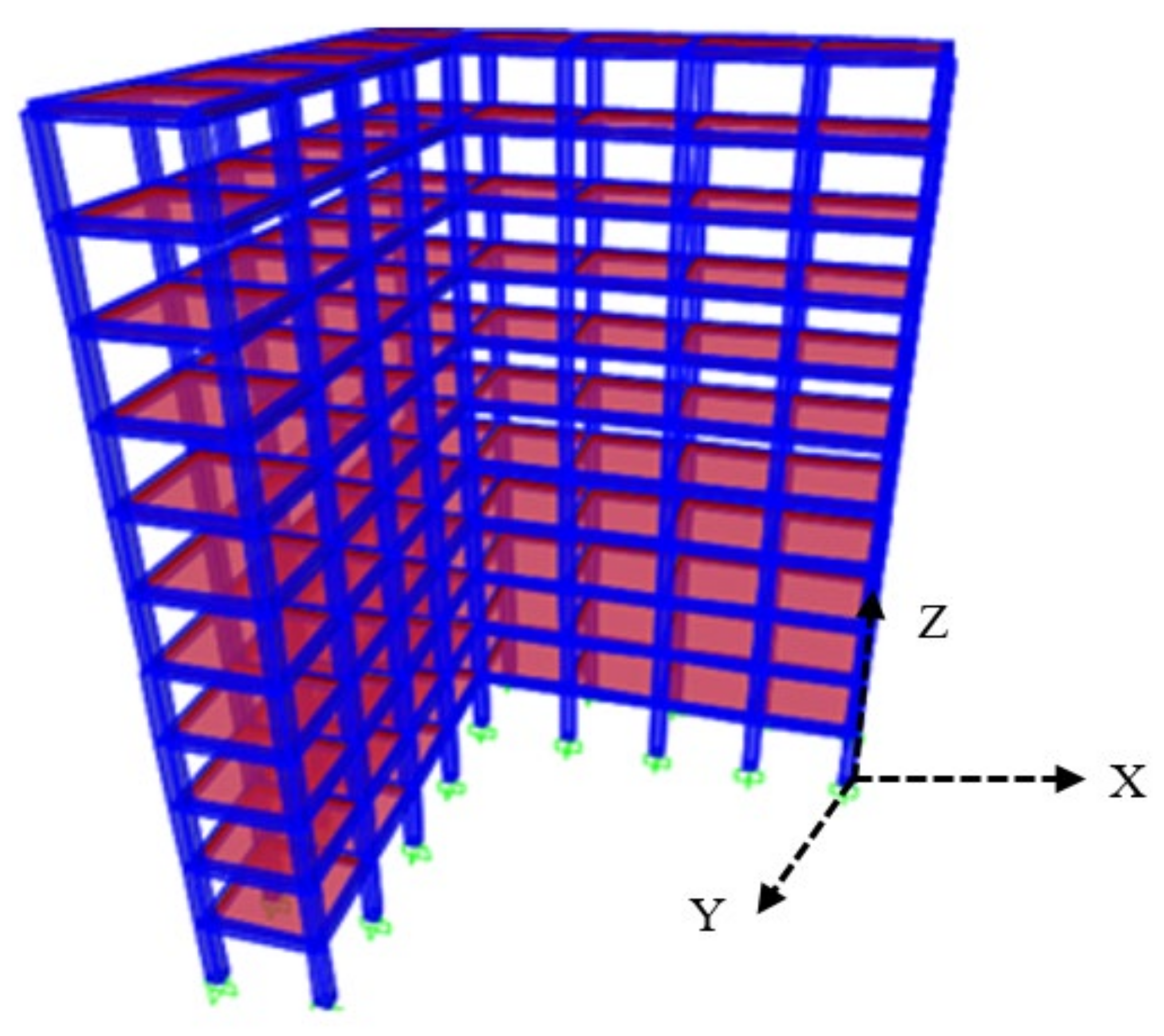
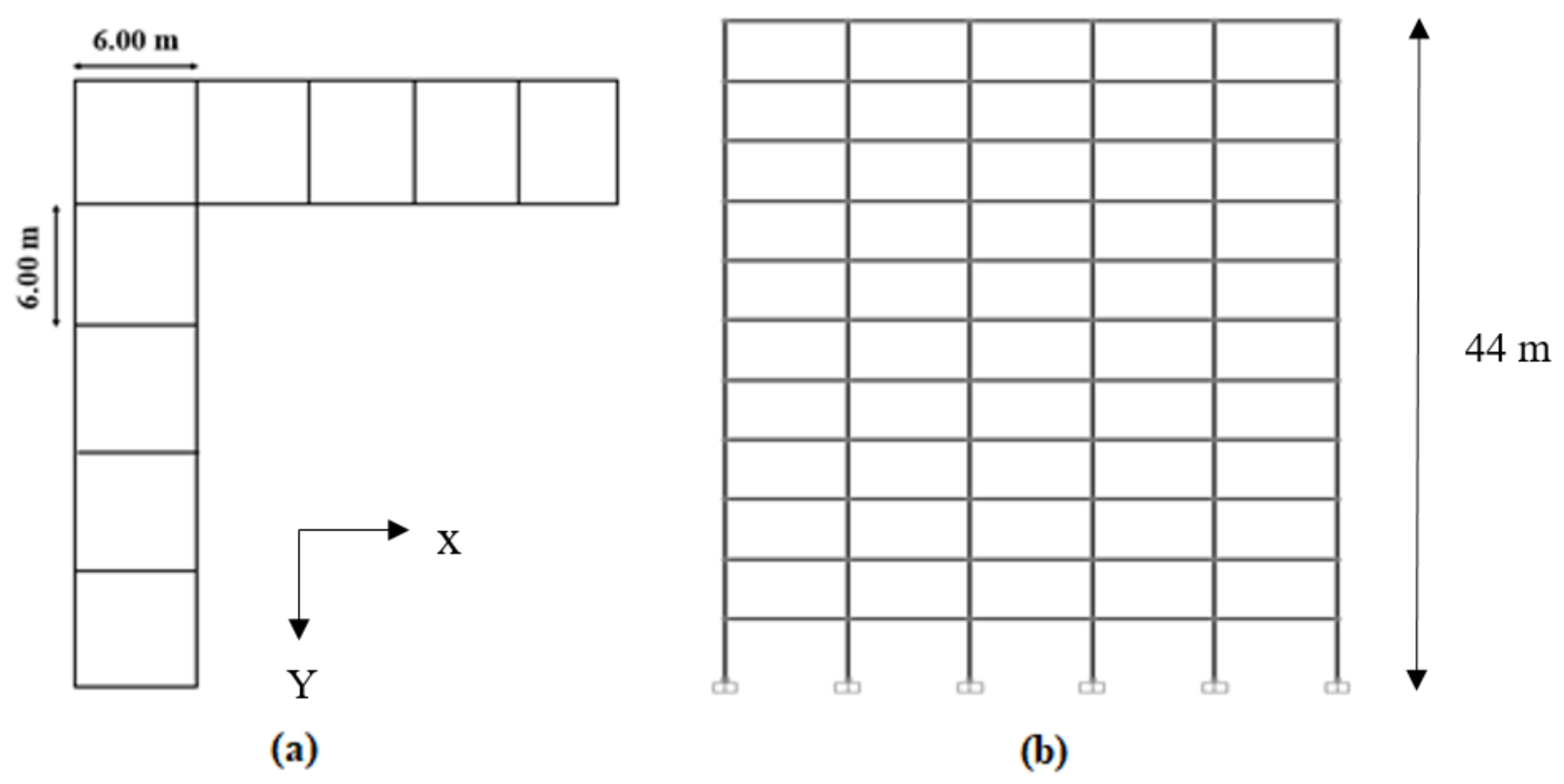
A high-rise, G+10-storey, L-shaped, unsymmetrical, reinforced, concrete building was considered in this study. The total plan area of the building is 324 m2. The plan and elevation of the unsymmetrical building are shown in Figure 1, while its 3D view is shown in Figure 2. The total height of the building is 44 m (Figure 1b) with an inter-storey height of 4 m. The collapse phenomenon is the combination of plastic and dynamic behaviour of the structural members. Though distributed plasticity provides slightly better results, in terms of modelling difficulties the default plastic hinges are assigned as per ASCE 41–17. The hinges were assigned in beams and columns at the starting and end portion of the member. The beam elements were assigned with M3 hinges, whereas for columns it was P-M2-M3 hinges. In the study, the lateral load-resisting system with bracings, URM infills, etc., was not included. The slab members were provided along with the rigid diaphragm action which was considered at each floor level that inhibited the actual behaviour of the building.
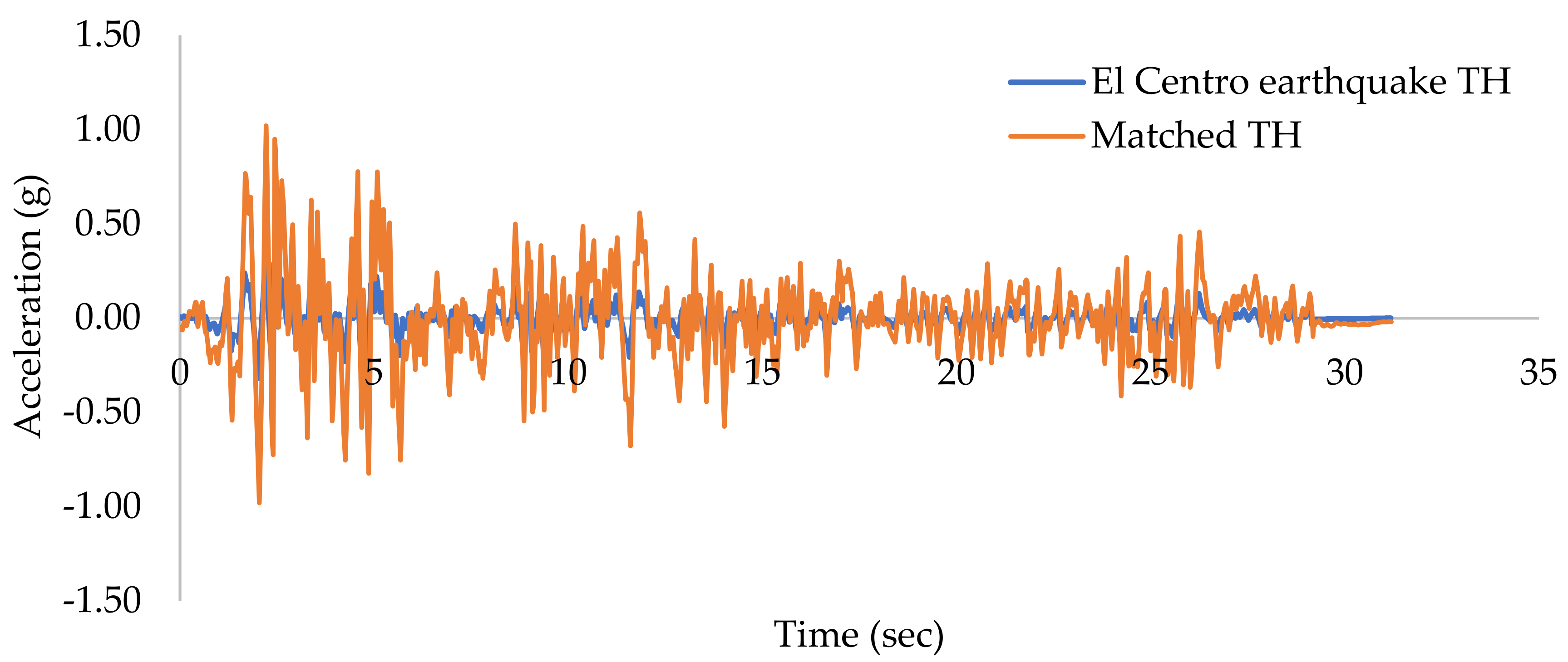
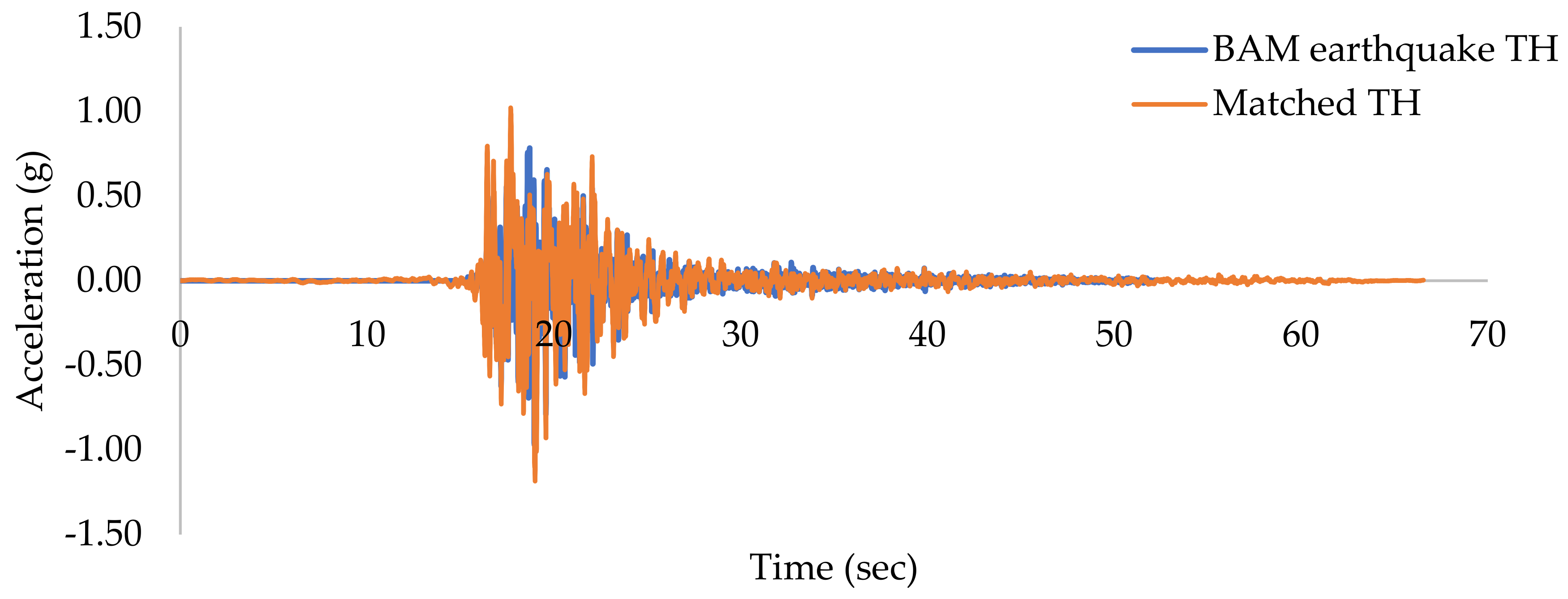
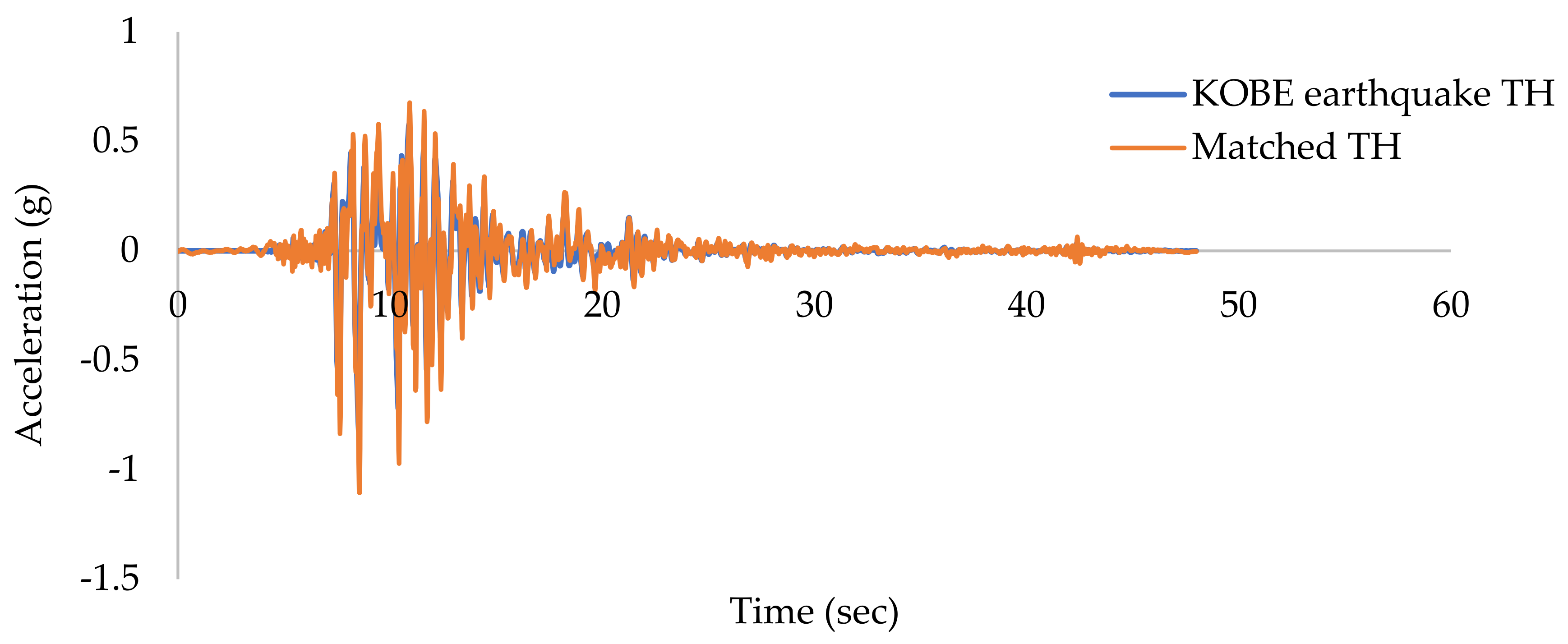
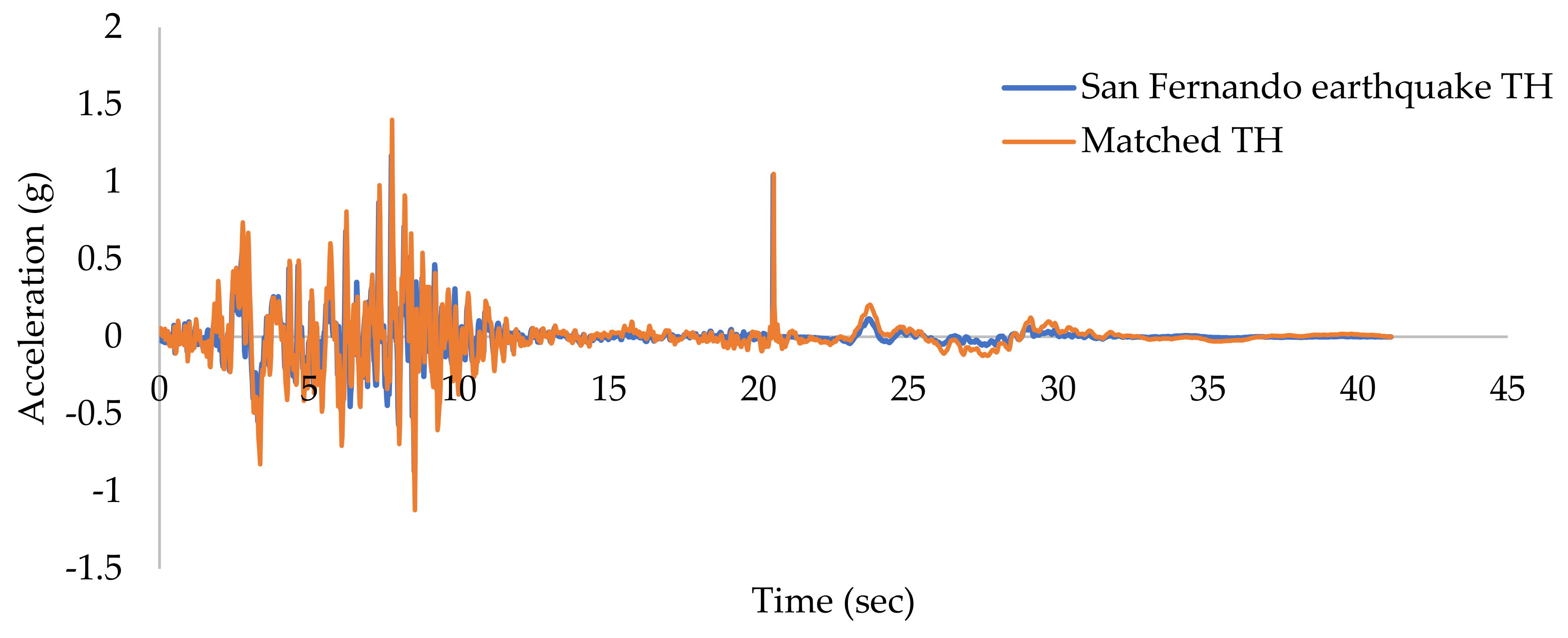
The building was designed in accordance with IS: 456–2000. The self-weight of concrete members such as beams, columns, slabs, and walls is included in the dead loads. Consideration was given to the wall load on the outside margin and the 150 mm slab thickness. The wall is 230 mm thick, and a floor finish of 1.5 kN/m2 was taken into account. A live load of 3 kN/m2 and a live roof load of 0.75 kN/m2 were also considered. For beams and columns, the concrete grades M25 and M30, respectively, were taken into consideration, and steel reinforcement with a 500 MPa yield strength was employed, while 5% damping with medium soil (Type II) was assumed according to IS 1893:2016 (Part I). Five various ground motions, namely El Centro, Bam, Kobe, San Fernando and Tabas, were considered for the present study (Table 1), with the corresponding spectrum-compatible ground motion time histories sketched in Figure 3, Figure 4, Figure 5, Figure 6 and Figure 7. Due to the asymmetry in the building orientation, unlike symmetrical building cases, the seismic loading was independently applied in both longitudinal (Ux) and transverse (Uy) directions. The behaviour of the building in both of the directions was therefore observed.
The building was designed with different cases of R (R equal to 3, 4, 5 and 6), considering 1.5 as the importance factor (I) and 0.36 as the zone factor (Z). It is worth highlighting that the response reduction factor is R = Ve/Vd, where Ve is the elastic base shear and Vd is the design base shear. The seismic behaviour of the building was analysed at each design level. The scale factor used is shown in Table 2 at design levels such as DBE and MCE levels.
3. Design Concept and Structural Details of the Building

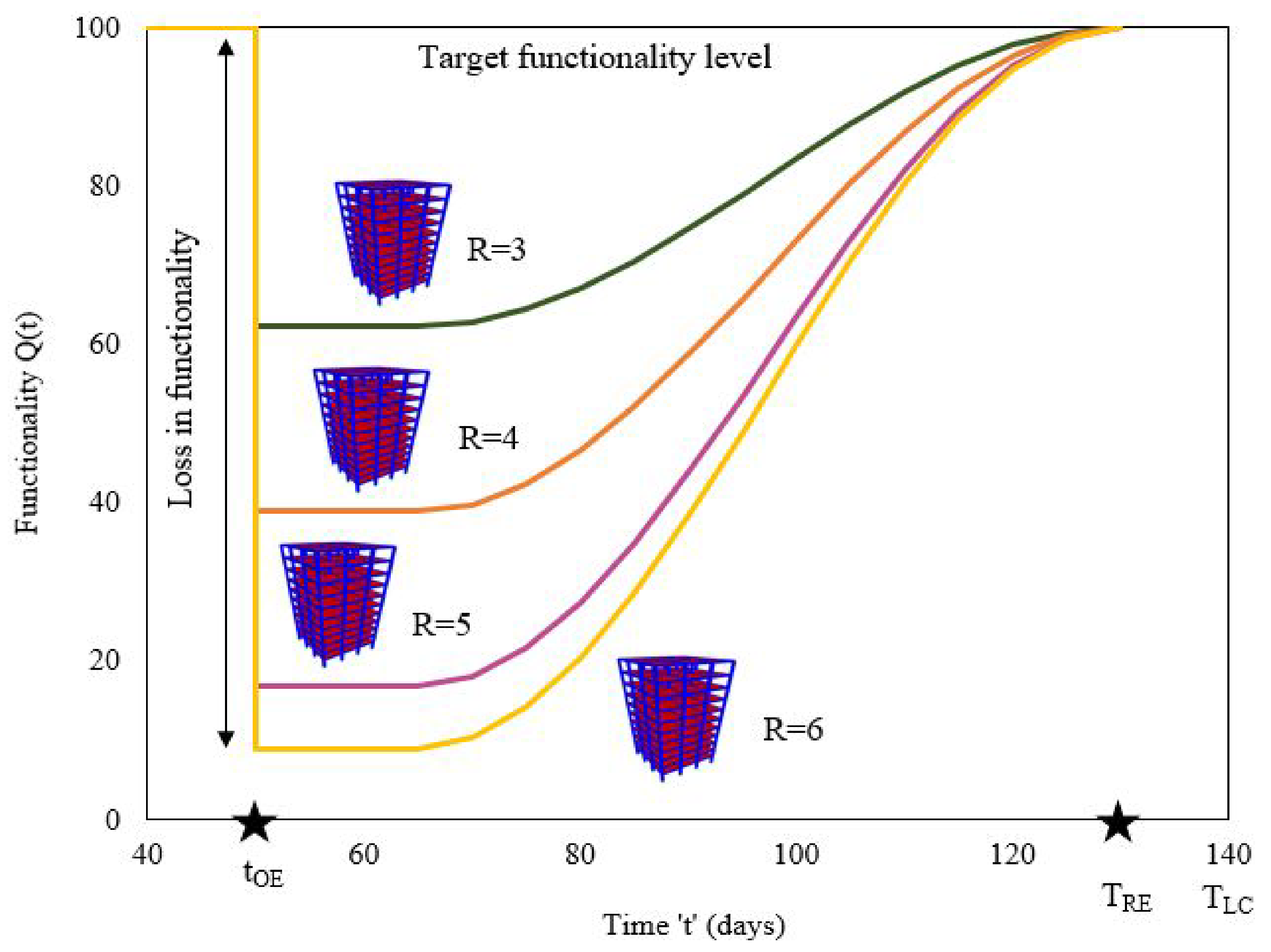
The design concept of the building was implemented using SAP2000 V22 [47], as per Indian Standards with respect to R = 3, 4, 5 and 6. The maximum performance levels at DBE and MCE design levels were maintained at the IO-LS level and CP-C level, respectively, based on which maximum R factor was recommended. To find the capacity curve of the building, the non-linear static pushover analysis using FEMA-440 [48] was performed, which was later followed by a non-linear time history analysis (NLTHA). For each case of the unsymmetrical building, the structural details are shown in Table 3. The graphical representation of change in building recovery with respect to R factors is shown in Figure 8.

3.1. Non-Linear Time History Analysis (NLTHA)

Using SAP2000, a NLTHA was carried out [49,50,51,52]. The investigation made use of the compatible ground motion time history (Figure 3, Figure 4, Figure 5, Figure 6 and Figure 7). Since the building plan orientation is asymmetrical, each building instance was subjected to independent unidirectional (Ux direction) and bidirectional (Ux and Uy) loads. The structure must be constructed for the simultaneous impacts of a full design earthquake loading in one horizontal direction plus 30% of a design earthquake load along a second horizontal direction, according to IS: 1893–2016. The matching El Centro time history data were chosen for the bidirectional loading condition since the El Centro ground motion was more prominent in the previous research.
At each design level, the maximum displacement was determined based on the loading conditions. The maximum displacement was recorded at the control node, which was assumed to be the top roof node, implying that local demands are controlled by global demands according to traditional design practice (using R-factors). For each building scenario, the maximum roof displacement among Ux and Uy directions under unidirectional and bidirectional loading circumstances was considered (Table 4 and Table 5).

3.2. Estimation of Ductility Demand of the Buildings

According to ATC-40 [53] recommendations, the yield (Δy) and ultimate displacements (Δu) were determined by performing bilinearisation of the building capacity curve found by performing non-linear pushover analysis. This was conducted to assess the structural vulnerability curve for estimating damage and loss. The ductility demand (μD) was estimated from the ultimate roof displacement and yield displacement (μD = Δuy), which indicates the displacement ductility demand of the buildings at each design level. The ductility demand under unidirectional and bidirectional loading conditions for each building case was found (Table 6 and Table 7).

3.3. Performance Level of the Building

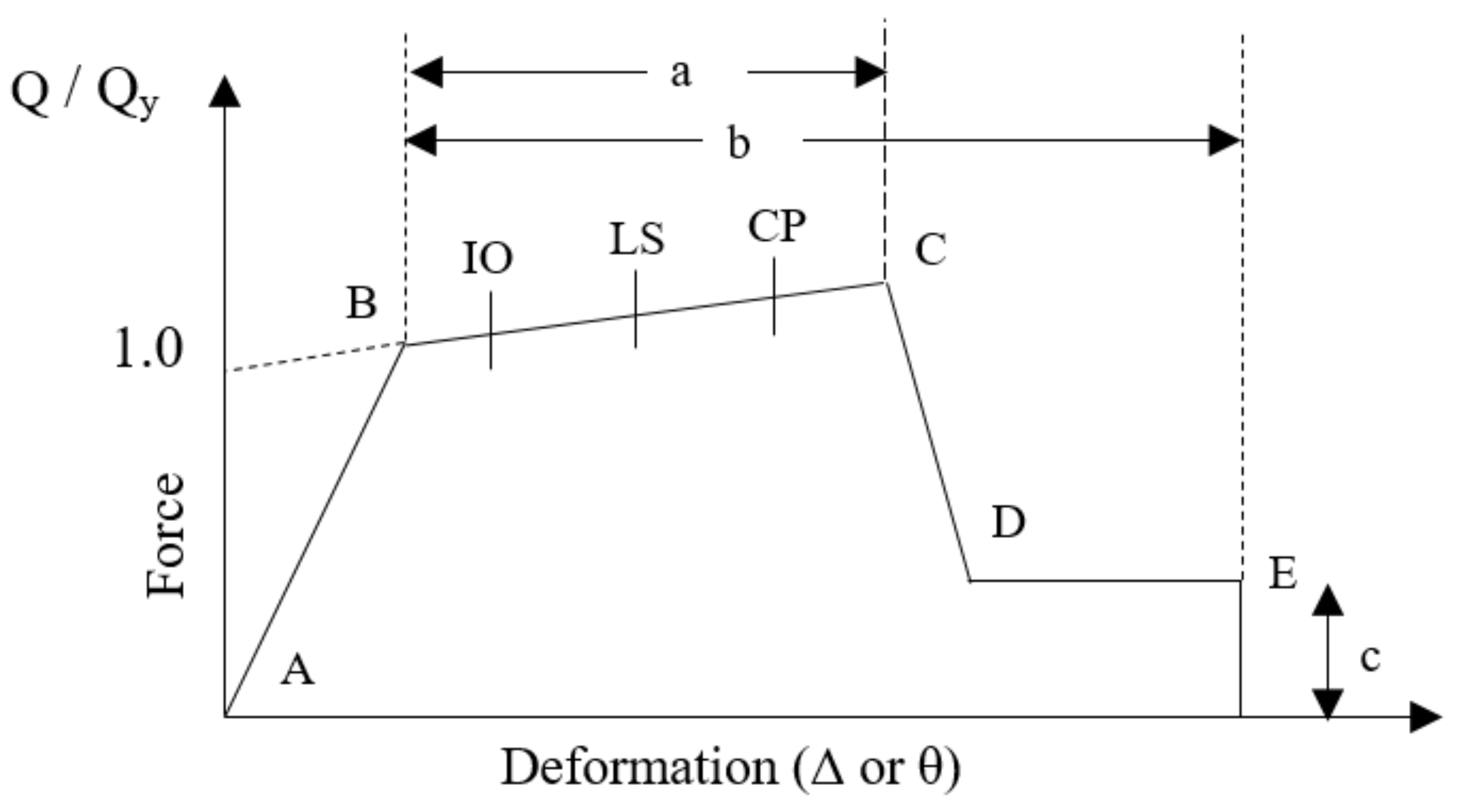
The extent of the building damage caused by the earthquake determines the structure level of performance. Immediate occupancy (IO), life safety (LS) and collapse prevention (CP) are three different performance levels (Figure 9). According to the American Society of Civil Engineers [54], the member non-linearity was accounted for in the form of plastic hinges. To assess the non-linear behaviour of the structure, plastic hinges were placed on the structural parts, such as beams and columns. With the structural member non-linearity, the NLTHA was performed to assess the structural capacity and performance level. The rotational capacity and constraints of the plastic hinges form the basis of the non-linear behaviour of the structure. The study considered the plastic hinge rotation limitations of 0.01, 0.025 and 0.050 for IO, LS and CP levels, respectively.
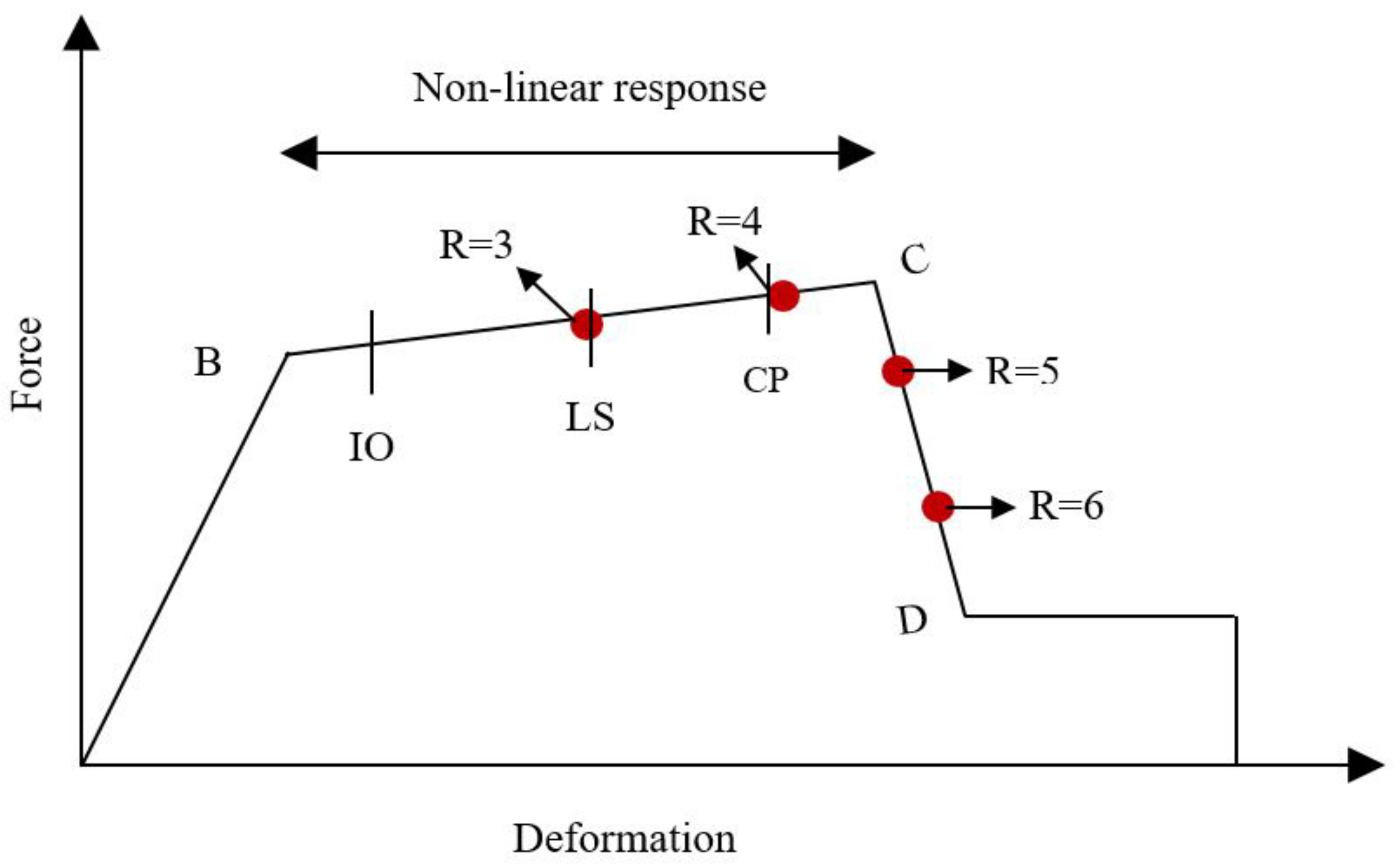
From the NLTHA, the building performance level was found at each design level under both unidirectional and bidirectional loading conditions (Table 8 and Table 9). The schematic representation of the performance point location of each building case with respect to MCE design level at both unidirectional and bidirectional loading conditions was shown in Figure 10 and Figure 11, respectively.
According to Table 8, the building performance level is impacted by changes in the R factor. At the DBE design level, the building lies at the IO level at R = 3 and 4, while at R = 5 and 6 it almost reaches the LS level. At the MCE design level (Figure 10), the building reaches IO-LS, almost CP, CP-C and CP-C at R equal to 3, 4, 5 and 6, respectively. It was observed that, at each R factor, the performance level was maintained to limit the ductility demand. At higher R factors (R = 5 and 6), the building lies at the CP-C level. This demonstrates how a greater R factor influences a building performance level because a higher R value calls for more ductility.
In the case of bidirectional loading, the building performance reduces significantly when compared with unidirectional loading (Table 9). At the DBE level, the building with R equal to 3 lies at the IO level, while at R = 6 it experiences the LS (LS ≤ CP) level under bidirectional loading conditions (Figure 11). Under unidirectional loading, at the MCE design level the building reaches IO-LS at R = 3, almost CP (LS ≤ CP) at R = 4, CP-C at R = 5 and CP-C at R = 6. With bidirectional loading, the building performance level reaches the LS level at R equal to 3, the CP-C level at R = 4, the C-D level at R = 5 and the C-D level at R = 6. This behaviour of the structure was not observed in the case of unidirectional loading where the building reaches the CP-C level at R equals 5 and 6 (Table 8). It clearly indicates that the consideration of bidirectional effects decreased the building performance level significantly, especially at higher R factors at both the DBE and MCE design levels.

3.4. Vulnerability Assessment

As per the HAZUS methodology [55], all of the buildings experience four damage states, i.e., slight, moderate, extreme and collapse. By creating fragility curves, it was possible to determine the vulnerability in terms of the likelihood of exceeding each damage condition in each situation. In this study, the fragility curves were plotted against cumulative probability exceedance of each damage state and spectral displacement. Using HAZUS methodology [55], the damage probability of exceedance is given by the following expression:
P d s S d = ϕ 1 β d s ln S d S d , d s
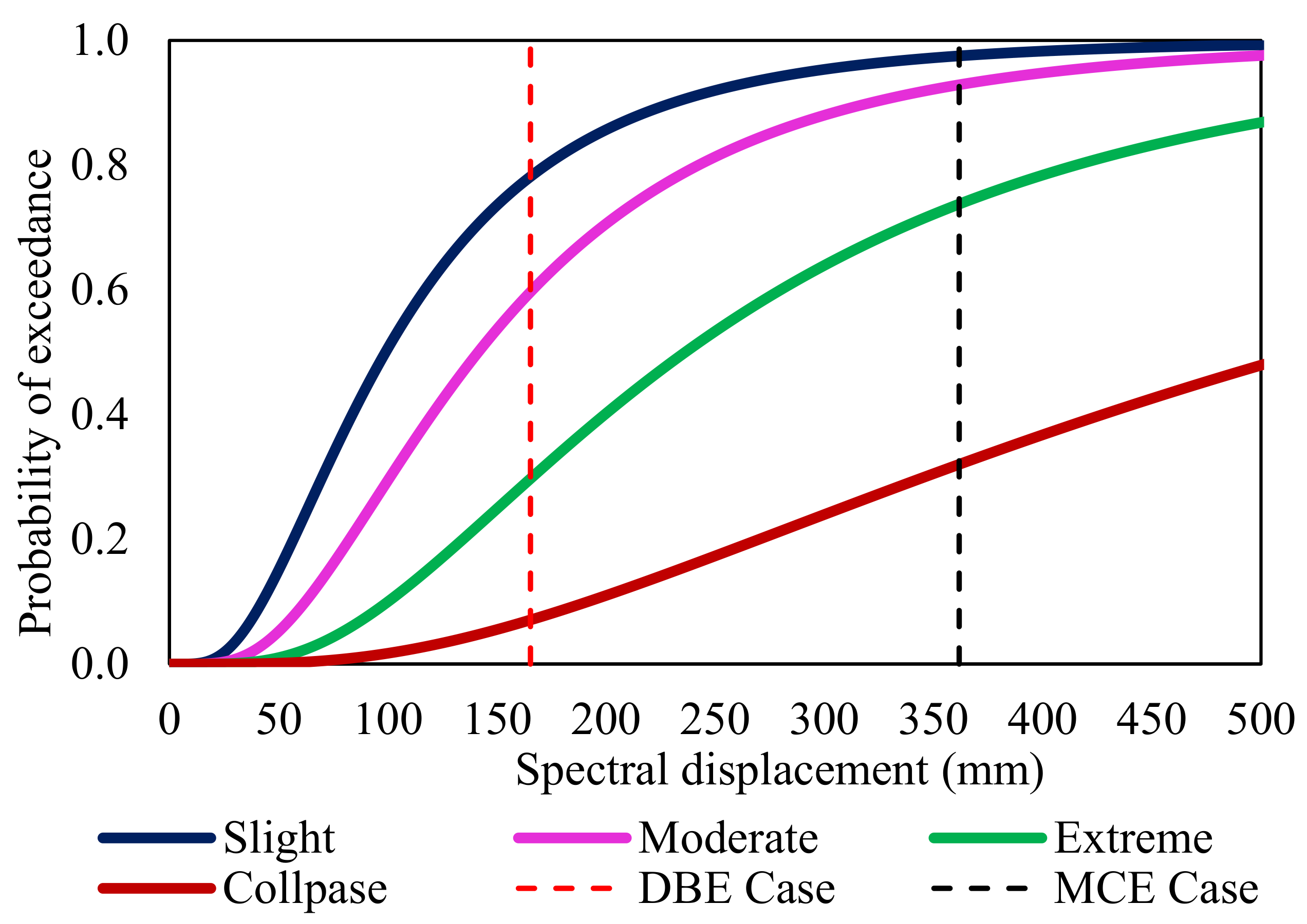
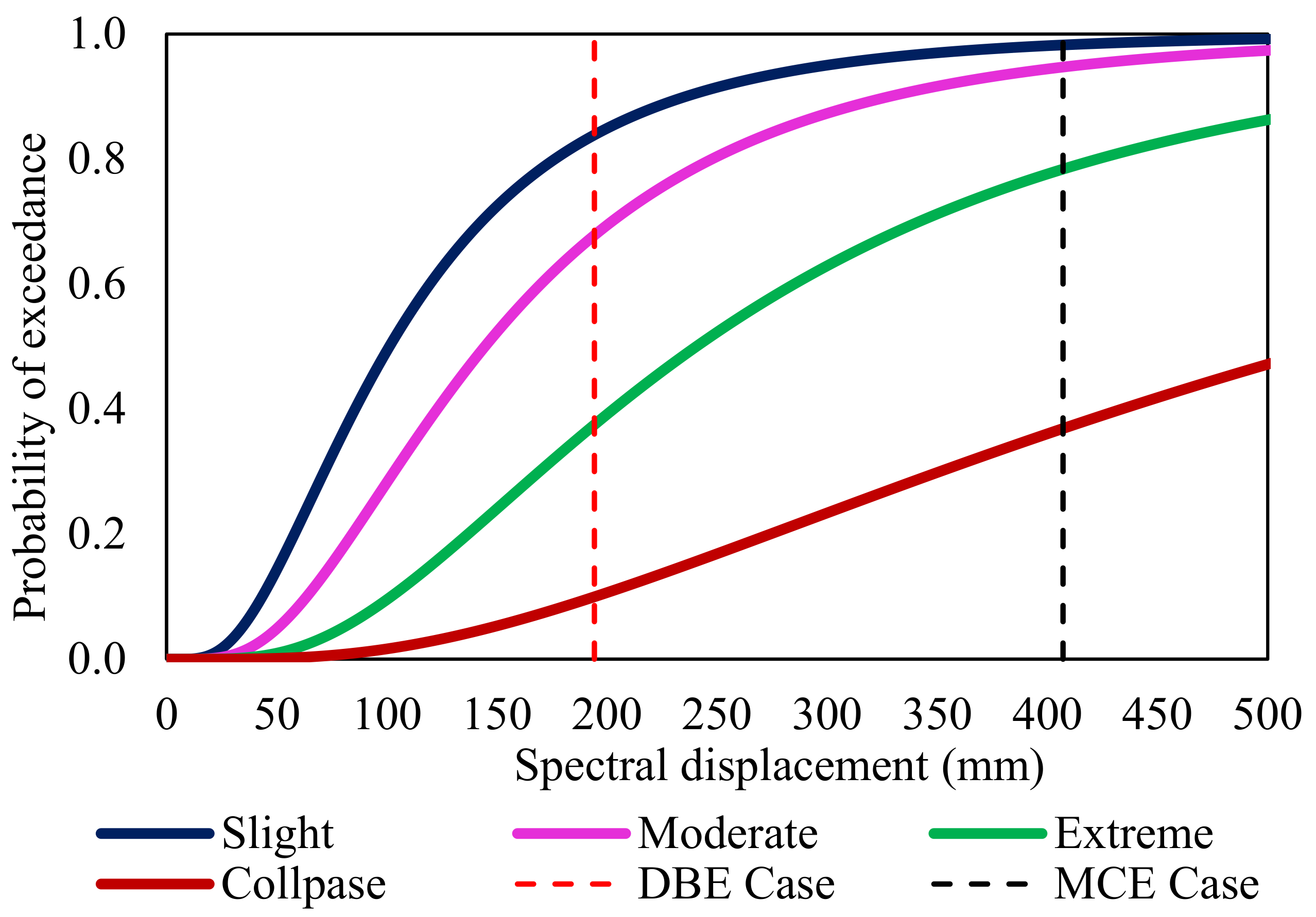
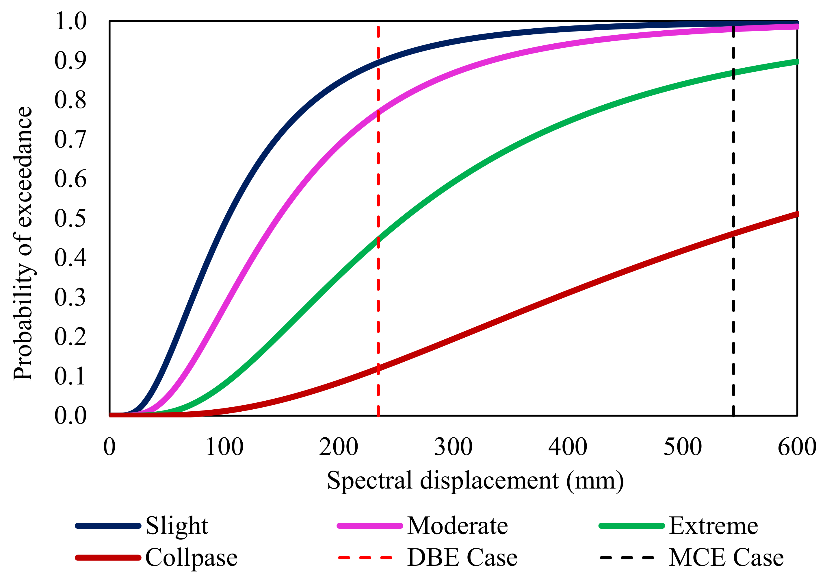
The median (Sd,ds) at each damage state with respect to spectral displacement was found from the proposed equations [56]. Lognormal standard deviation (βds) values that describe the variability (dispersions) of fragility curves are developed for each damage state (i.e., slight, moderate, extensive and complete). The total variability of each structural damage state (βds) was taken from the HAZUS MR4 technical manual. The spectral displacement (Sd) on the x-axis and the probability of exceedance on the y-axis were used to illustrate the vulnerability in terms of the fragility curve. The probability of exceeding the stated damage level or state is shown by the y-axis, which ranges from 0% to 100%. For each example of the construction, fragility curves were created (Figure 12, Figure 13, Figure 14 and Figure 15).
From the fragility curves, the probability of the building exceeding each damage state was evaluated. The vertical line that intersects the fragility curves of various damage states was shown with regard to the spectral displacement at each design level. The likelihood percentage of exceeding for that particular damage condition is provided by the intersection point.
From Figure 12, Figure 13, Figure 14 and Figure 15, it was observed that at the DBE design level, the building with R = 5 and 6 (Cases III and IV) shows 45 to 55% certainty of experiencing extreme damage. The building in all cases shows less than a 20% probability of experiencing a collapse damage level. This shows that the building has much less collapse probability at the DBE design level. At a higher design level (MCE), it was noted that all of the building cases (Case I to IV) have more than 90% certainty to experience moderate damage and 70% certainty to experience extreme damage states. Since the collapse probability of the building ranges from 45 to 57% at higher R factors such as R = 5 and 6, it shows that the building is more prone to the collapse damage level, which affects the recovery planning of a post-disaster event. Under bidirectional loading, at the MCE design level, the building Cases I and II have more than 75–82% certainty of experiencing an extreme damage state, whereas Cases III and IV have 88–92% certainty of experiencing an extreme damage state. The slight increase in the damage probability was observed at a higher R factor with bidirectional loading.

3.5. Estimation of Damage–Loss Ratio

The estimation of damage losses due to post-disaster events is uncertain as it depends on location and environmental conditions. Based on the loss estimation, the strategic recovery plan was fixed to recover back the functionality in the control period of time. In estimating the functionality of the building, the losses are incorporated in terms of loss function, denoted as L(I,TRE). There are two types of losses involved in finding the loss function, namely direct (LD) and indirect (LID) economic losses. The direct damage–loss ratio was found using Equation (2).
L D = P E ( D S = K ) × r K
where K is the harm state of the building, PE (DS = K) is the discrete damage probability that the building was in that state when the incident occurred and rK is the damage ratio associated with discrete damage probability of each damage state which was estimated using the HAZUS MR4 technical manual [55]. The damage–loss ratios under both loading conditions for each building cases was found (Table 10 and Table 11). The direct damage losses were estimated and then used to evaluate the building resilience.
According to these tables, the damage–loss ratio increased for each building case at each design level. Larger R factors (R = 5 and 6) result in a higher damage–loss ratio be-cause of a higher ductility demand. This increase in loss ratio has an adverse effect on the building resilience. A slight increase in the damage–loss ratio under bidirectional loading was observed, which affects the resilience of the building.

3.6. Estimation of Building Resilience from Functionality Curves

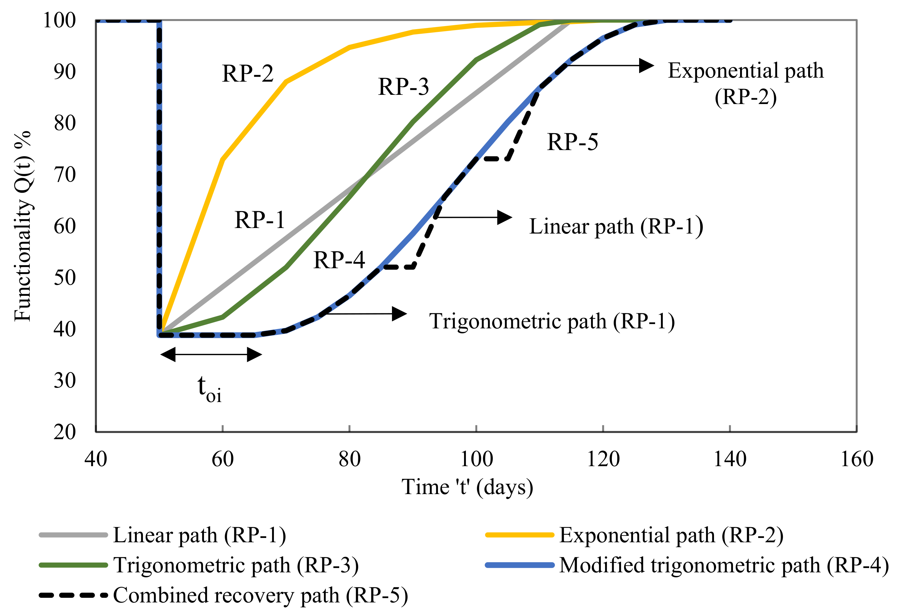
To estimate the building resilience, functionality curves for each building case were developed with respect to each design level, using various recovery functions. The analytical recovery functions, such as linear (RP-1), exponential (RP-2) and trigonometric (RP-3) recovery paths, were proposed by Bruneau et al. [57] and Kumar et al. [58]. The functionality curve in terms of resilience was found as follows:
Functionality:
Q ( t ) = 1 { L I , T R E × [ H t t O E H t t O E + T R E ] × f r e c t , t O E , T R E }
The time of occurrence of a seismic event is designated as tOE, its recovery time is designated as TRE, and its Heaviside step function is designated as H(). For the purposes of this study, tOE is set at 50 days, and total recovery time is calculated as 65 days with a total control time period (TLC) of 140 days. The analytical equations for each recovery function are the following:
Linear   function :   f r e c t , t O E , T R E = 1 t t O E T R E
Exponential   function f r e c t , t O E , T R E = exp t t O E ln 200 T R E
Trigonometric   function :   f r e c t , t O E , T R E = 0.5 1 + cos Π t t O E T R E
Along with conventional, two different recovery paths named modified trigonometric path (RP-4) and combined recovery path (RP-5) were also considered.
The idea behind the parameter introduction was that, under realistic conditions, recovery could not begin after a seismic event had happened (Figure 16). Real-world situations necessitate a careful assessment of the structural damage before the recovery procedure can begin. The functionality and recovery equations were adjusted as follows in light of this.
In addition to the ‘toi’ parameter, the modified trigonometric path is the fourth recovery path (RP-4) which has an initial delay in the recovery process, whereas the combined recovery path is the fifth recovery path (RP-5) which has a certain breakdown in the recovery process (Figure 16). The functionality Equation (3) now includes the new argument ‘toi’. Based on this, the functionality and recovery equations were modified as follows:
Q ( t ) = 1 L I , T R E × H t t O E t o i H t t O E + T R E t o i × f r e c t , t O E , T R E , t o i
f r e c t , t O E , T R E , t o i = 0.5 1 + cos Π t t O E t o i T R E

3.7. Resilience of Each Building Case under Unidirectional Loading

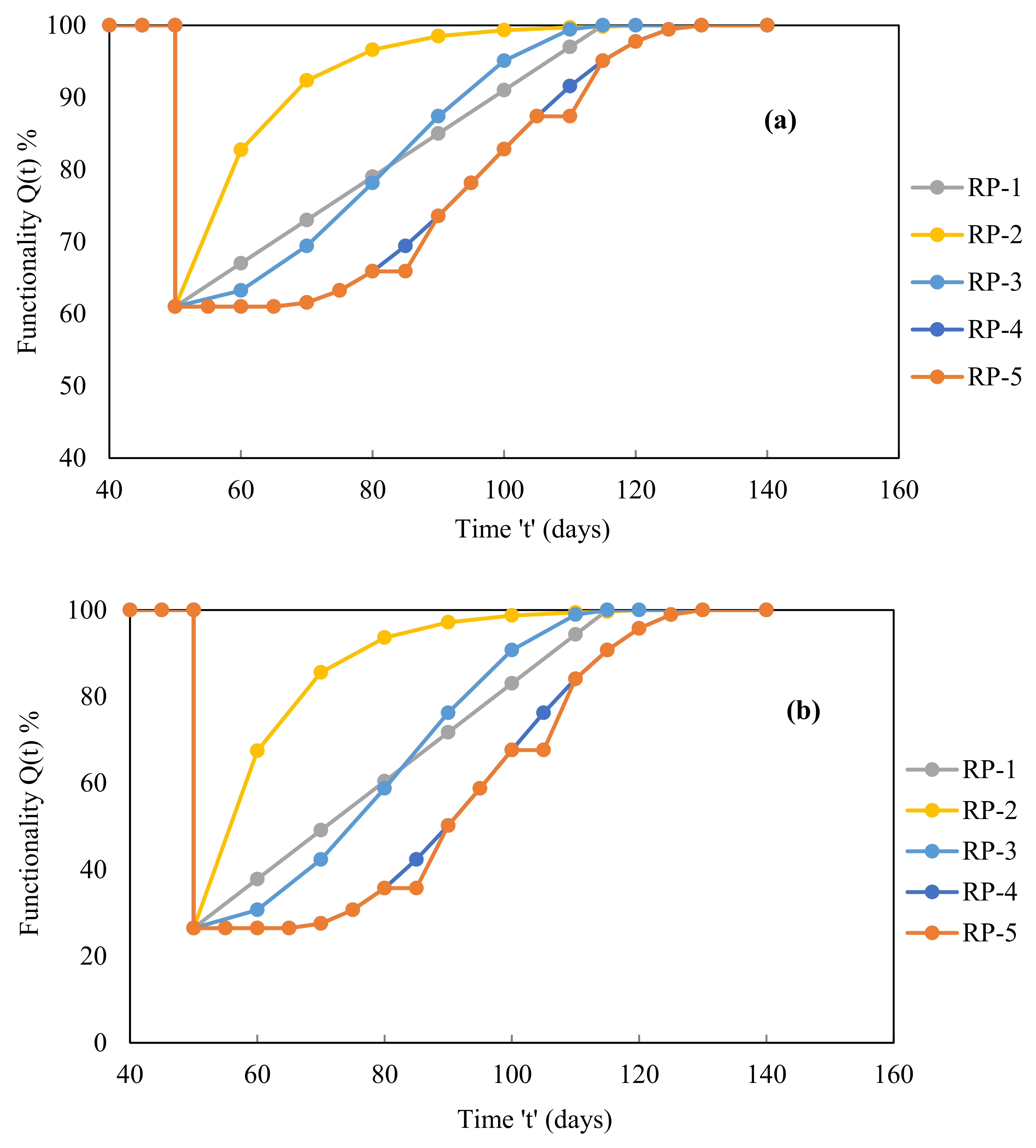
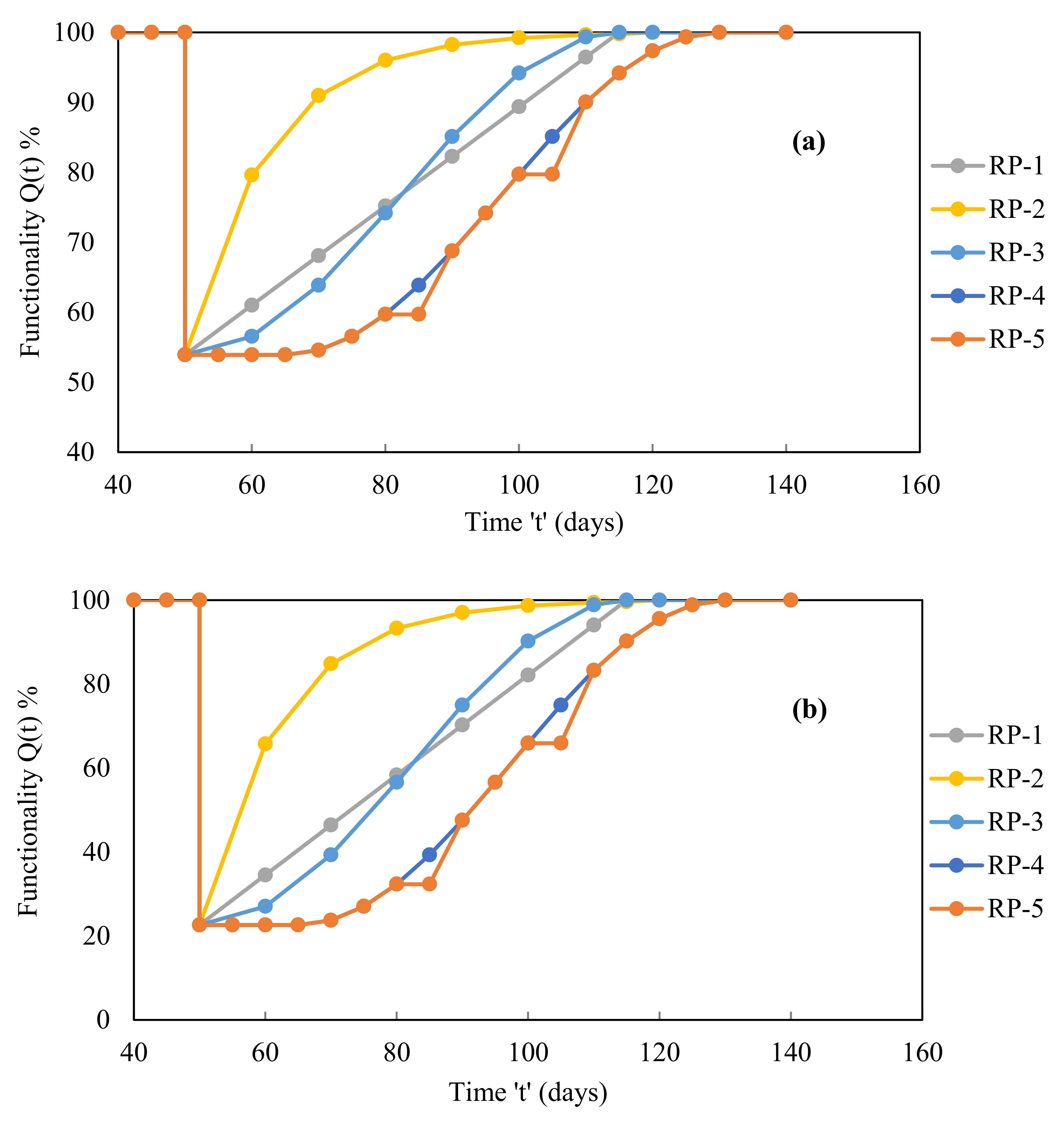
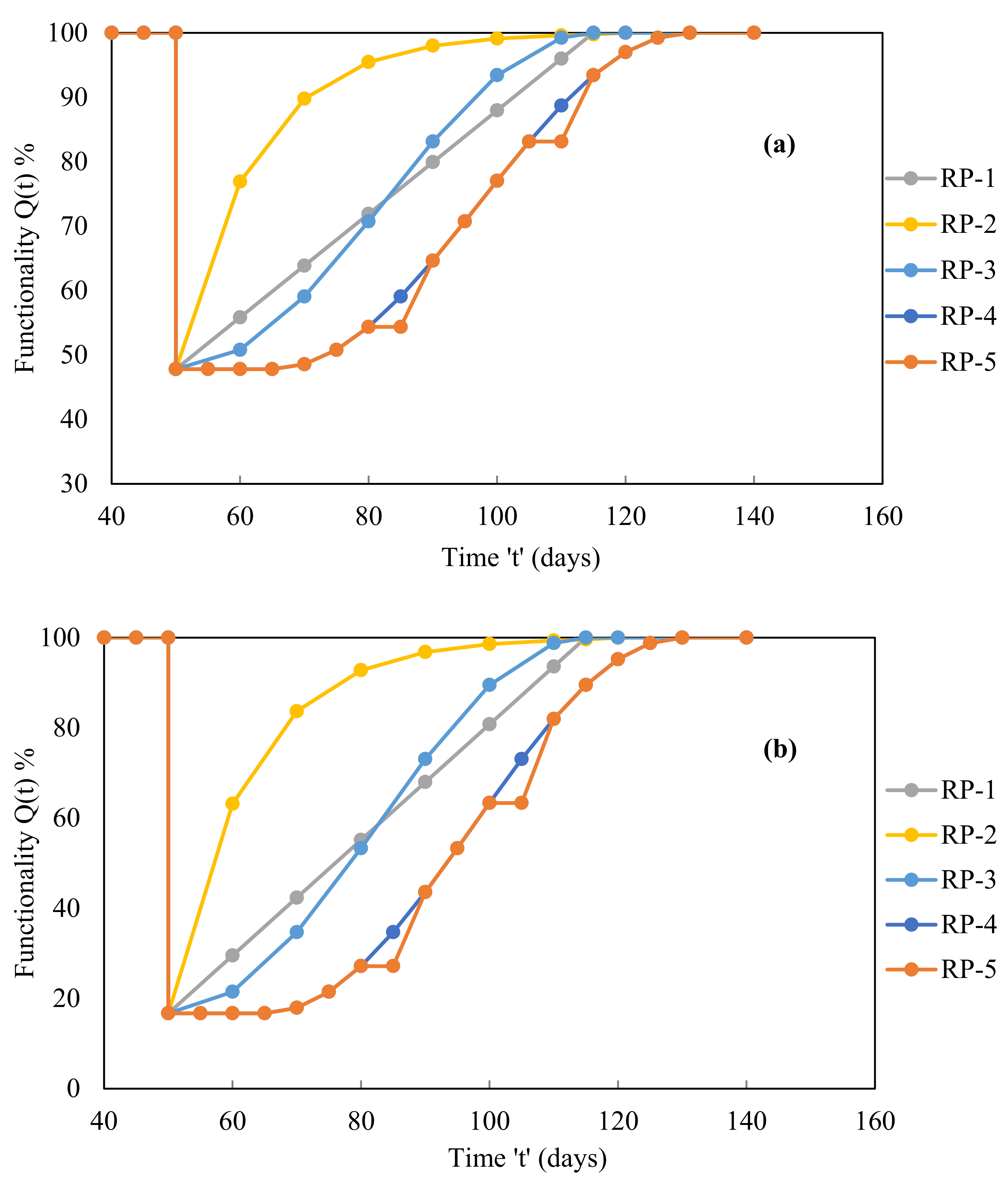
Under conditions of unidirectional loading, functionality curves corresponding to each design level were developed (Figure 17, Figure 18, Figure 19 and Figure 20) based on several recovery paths. The area below and above the functionality curves demonstrates the building resilience and loss of resilience (LOR). Utilising the Origin software, the curve area was discovered.
The functionality curves were plotted using five different recovery paths at each design level for Case I building (Figure 17). At the time of the occurrence of a seismic event, the functionality of the building dropped down from 100% to 61.00% at the DBE design level and from 100% to 26.50% at the MCE design level. The loss in functionality was estimated to be 39.00% and 73.50% at the DBE and MCE design levels, respectively. The loss of functionality was higher at the MCE level which was due to a higher damage–loss ratio when compared with the DBE design level.
Figure 18 shows the different functionality curves at various design levels for the Case II building. The functionality drops from 100% to 54% at the DBE level and from 100% to 23% at the MCE level. The functionality loss was estimated to be 46% and 77% at the DBE and MCE design levels, respectively.
For the Case III building, the different functionality curves were developed at design levels (Figure 19). At the time of occurrence of the seismic event (on the 50th day), the functionality is reduced from 100% to 48% and 17% at the DBE and MCE design levels, respectively. The functionality loss was estimated to be 52% and 83% at the DBE and MCE design levels, respectively.
Figure 20 depicts the functioning curves for the Case IV building utilising various recovery pathways. The functionality decreases from 100% to 41% at the DBE design level and from 100% to 13% at the MCE design level at the time of the seismic event (on the 50th day). At the DBE and MCE design levels, the functionality loss was calculated to be 59% and 88%, respectively.
The region under and above the functioning curves (Figure 17, Figure 18, Figure 19 and Figure 20) represents the building resilience and loss of resilience (LOR), respectively. Origin software was used to calculate the area of the curve. The functionality curves were used to calculate the resilience for each building case (Table 12, Table 13, Table 14 and Table 15).
At the DBE design level, building resilience corresponds to Case I ranging from 81% to 76%, and at the MCE design level resilience ranges from 63% to 55% (Table 12). When compared to the DBE level for RP-5, the highest reduction in resilience at the MCE level was around 28%. The recovery path RP-2 was not always realistically feasible, as was already mentioned. The remaining recovery pathways were contrasted with each other (RP-1, RP-3, RP-4 and RP-5). When compared to the standard recovery path RP-3, roughly 13% lesser resilience was seen at the DBE level and 15% less was seen at the MCE design level for the proposed recovery path RP-4. This resulted from the recuperation process breaks and the early delay in the beginning. At the DBE and MCE design levels, the maximum loss of resilience (LOR) was discovered to be approximately 24% and 45%, respectively.
Table 13 shows that, with regard to recovery paths, the resilience of the Case II building varies between 77% and 72% at the DBE design level and between 61% and 53% at the MCE design level. At the DBE and MCE design levels, respectively, it was discovered that the maximum loss of resilience (LOR) was estimated to be approximately 28% and 47%.
Building resilience in Case III (Table 14) at the DBE design level ranges from 74% to 68%, and 58% to 49% at the MCE design level. At the DBE and MCE design levels, respectively, the maximum loss of resilience (LOR) was estimated to be around 32% and 51%.
Building resilience in Case IV at the DBE design level varies from 71 to 64% (Table 15) and at the MCE design level it varies from 56 to 47%. At the DBE and MCE design levels, the maximum loss of resilience (LOR) was observed to be about 36% and 53%, respectively. It was found that the building corresponding to Cases III and IV (R = 5 and 6) exhibits less resilience than other building cases at both design levels. This resulted from the strong need for ductility at R equals 5 and 6 (Cases III and IV). It was discovered that the building resilience at both design levels significantly decreases for Cases III and IV. This was brought on by the building’s increased ductility requirements at the DBE and MCE design levels in comparison with Cases III and IV.

3.8. Resilience of Each Building Case under Bidirectional Loading

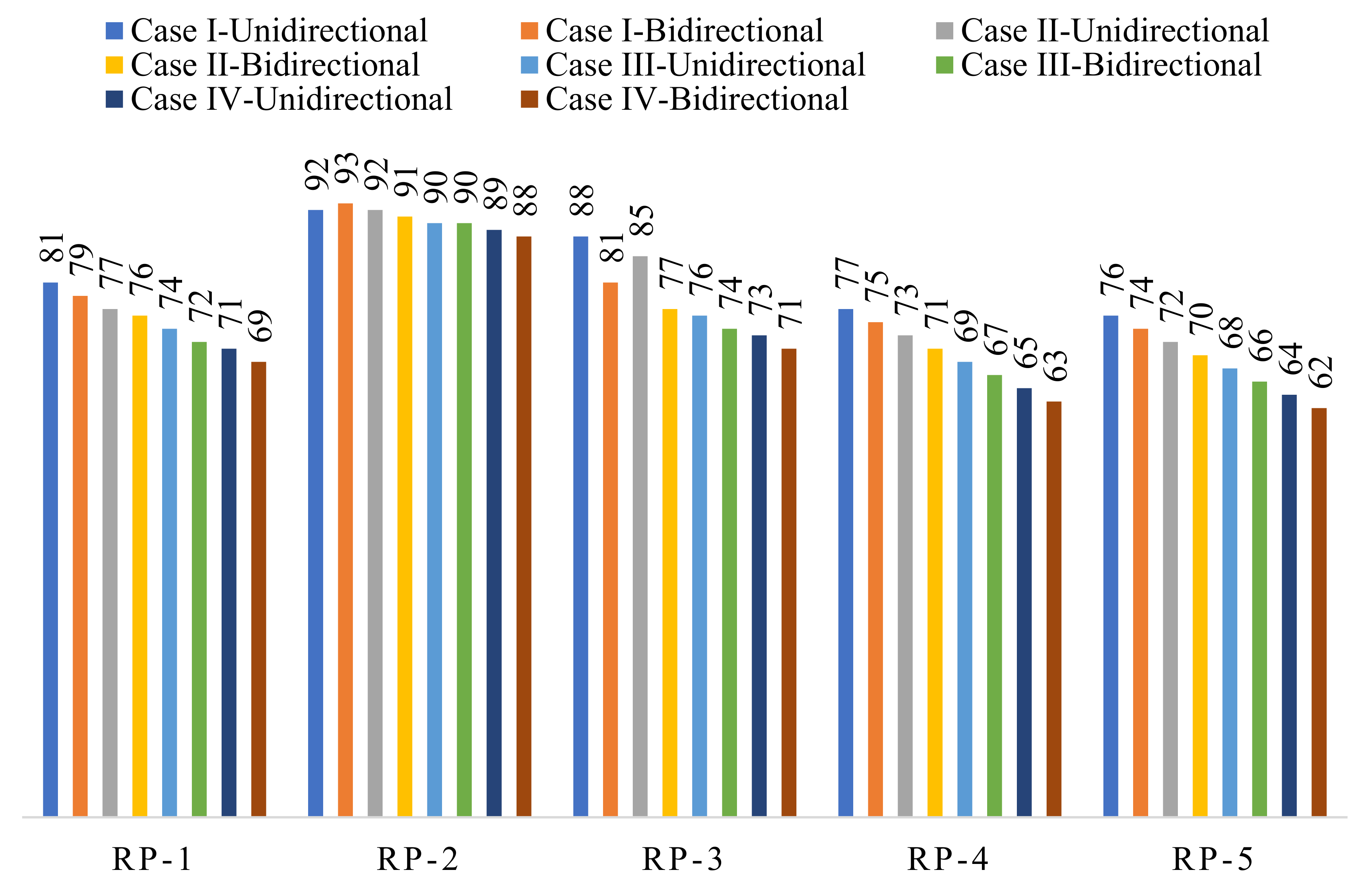
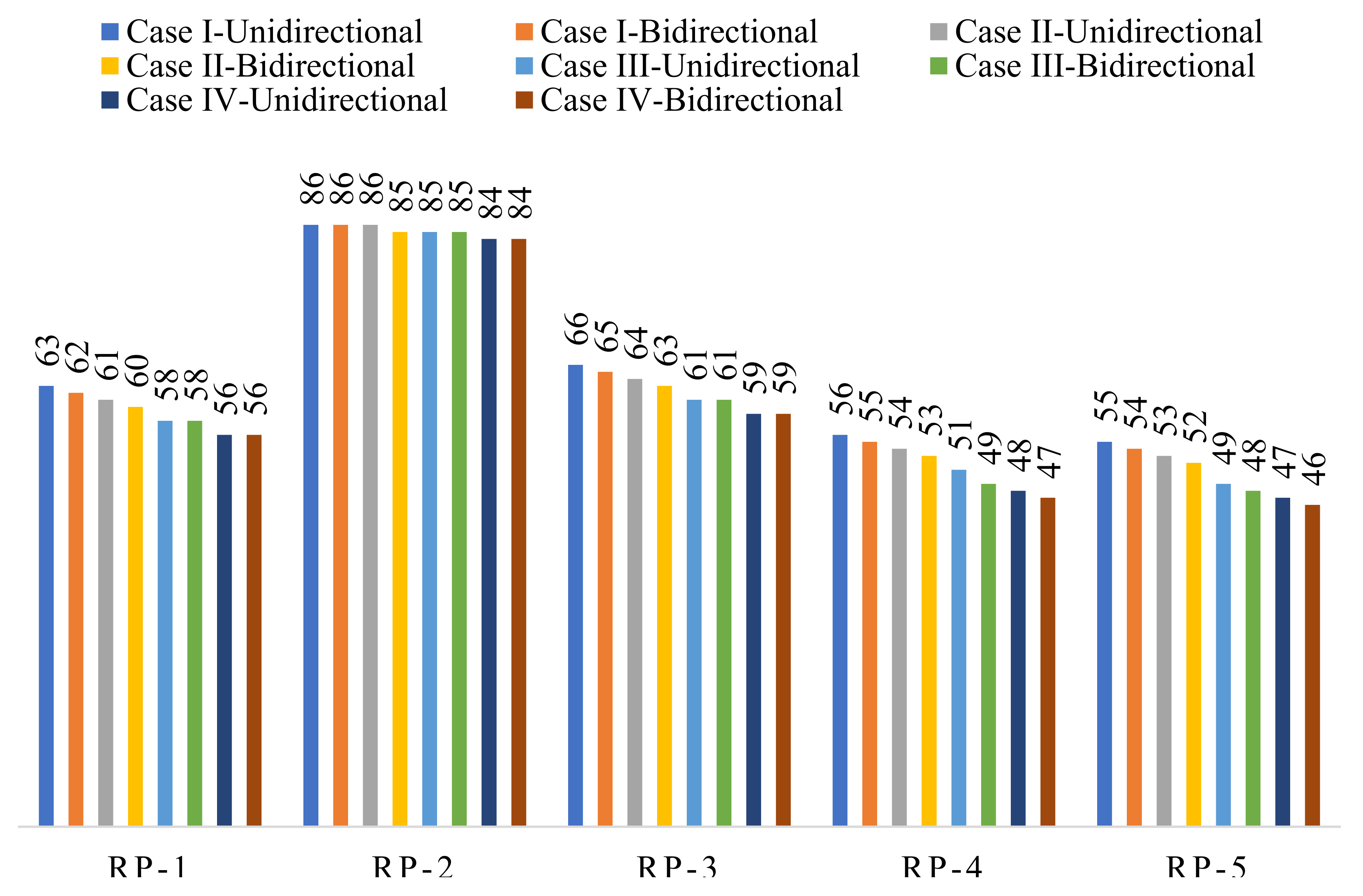
The resilience of each building case under bidirectional loading was found (Table 16, Table 17, Table 18 and Table 19). A comparison of resilience was made between unidirectional and bidirectional loading conditions (Figure 21 and Figure 22).
From Figure 21, it was observed that the variation in resilience was not significant with bidirectional loading at the DBE design level. In all of the building cases at the DBE level, the resilience under bidirectional loading was marginally less when compared with the unidirectional loading. At the MCE design level, the same variation in resilience was observed when compared with unidirectional and bidirectional loading conditions (Figure 22). The variation in resilience was not significant, which was due to the fact that the damage ratio with bidirectional loading did not vary much when compared with unidirectional loading.

4. Conclusions

In this study, the selection of appropriate R factors was performed for an unsymmetrical L-shaped RC building in accordance with resilience, performance level and ductility demand aspects. The study proposes a framework in the R factor selection, and it can be adapted to other irregular buildings since only the modelling and loading conditions will be varied for each type of building. The framework remains the same which proposes various recovery paths in the assessment of R factors with resilience considerations. The seismic response of the building has to be taken care of via proper selection of R factors. It is possible to consider the irregularity in the design level as did in the present study. To plan for post-disaster recovery, the building irregularity found using the R factor should be incorporated with resilience consideration. Though several codes are silent on the above aspects, the present study gives a detailed description about the basis of R factor selection in the design. In this study, the seismic performance of an unsymmetrical building subjected to unidirectional and bidirectional loadings at two design levels such as the DBE and MCE levels was assessed. Some of the major conclusions of the study are as follows.
  • All of the cases of the unsymmetrical building reported a moderate ductility requirement at the DBE design level for both unidirectional and bidirectional loadings. The building almost meets the high ductility demand and corresponds to R equalling 5 and 6 at the MCE design level. This demonstrates that the ductility demand rises as the R factor increases. Buildings with lower ductility demands are generally more affordable to construct. This aids in making the right choice of R factors for the building design.
  • A higher R factor has an impact on building performance levels due to higher ductility demand. The performance level at the DBE design level advances from the IO level (at R equals 3 and 4) to the IO-LS level (at R equals 5 and 6). The building performance level varied significantly (IO-LS level to CP-C level) from R = 3 to 6 at the MCE design level. Under bidirectional loading, the performance level of the building has higher R (R = 5 and 6) cases which lie at the C-D level. This shows that the building reaches a full collapse damage state without having any residual strength. This was due to the reduction in transverse member participation in structural stiffness due to a bidirectional loading effect at a higher R factor. Thus, in the case of unsymmetrical building, the bidirectional effect significantly alters the building performance level with a marginal increase in ductility demand.
  • Under both unidirectional and bidirectional loading conditions, with respect to the DBE and MCE design level, the loss of resilience (LOR) was less than 30% and 50% at R = 3 and 4 (Cases I and II), respectively. At higher R factors of 5 and 6, the LOR marginally increases with more than 50% LOR at the MCE design level. At unidirectional and bidirectional loadings, though the building at R = 5 and R = 6 suffers significant functionality loss at the MCE level, the building holds almost 50% resilience. However, the recovery of the building from that level may lead to higher retrofitting costs to recover back to its target performance level.
  • It was concluded that as the building reaches a higher ductility demand with a value of 4.98 at R = 5 along with a performance level at the CP-C level, the maximum R factor for the considered unsymmetrical building can be recommended up to 4 with respect to unidirectional loading. Due to asymmetry, the bidirectional loading is predominant in the case of the MCE design level, which alters the building’s performance level to CP-D and increases the ductility demand to a higher level. This resulted in a reduction in maximum values of the R factor from 4 to 3, as at R equals 4, 5 and 6 the building experiences a higher ductility demand and a higher performance level with a marginal increase in loss of resilience.
The study concludes that the building resilience, performance level and ductility demand influence the selection of the R factors in accordance with the asymmetry of the building along with a consideration of directional effects.

Author Contributions

Conceptualisation, S.P. and G.G.; data curation, P.K.G.; formal analysis, S.P. and P.K.G.; investigation, S.P.; methodology, S.P. and G.G.; project administration, S.P. and P.K.G.; supervision, G.G., C.C. and L.G.; validation, S.P.; visualisation, G.G.; writing—original draft, S.P., P.K.G. and G.G.; writing—review and editing, S.P., P.K.G., G.G., C.C. and L.G. All authors have read and agreed to the published version of the manuscript.

Funding

This research received no external funding.

Institutional Review Board Statement

Not applicable.

Informed Consent Statement

Not applicable.

Data Availability Statement

All data, models and codes generated or used during the study appear in the submitted article.

Conflicts of Interest

The authors have no relevant financial or non-financial interests to disclose.

References

  1. ASCE/SEI 7-22; Minimum Design Loads and Associated Criteria for Buildings and Other Structures. American Society of Civil Engineers: Reston, VA, USA, 2005.
  2. EN 1998-1; Eurocode 8: Design of Structures for Earthquake Resistance. 1st ed. BSi—Brussels: Brussels, Belgium, 2004.
  3. IS: 1893; Part-1. Indian Standard Criteria for Earthquake Resistance Design of Structures. Bureau of Indian Standards: New Delhi, India, 2016.
  4. Mondal, A.; Ghosh, S.; Reddy, G.R. Performance-based evaluation of the response reduction factor for ductile RC frames. Eng. Struct. 2018, 56, 1808–1819. [Google Scholar] [CrossRef]
  5. Abdollahzadeh, G.; Sadeghi, A. Earthquake recurrence effect on the response reduction factor of steel moment frame. Asian J. Civ. Eng. 2018, 19, 993–1008. [Google Scholar] [CrossRef]
  6. Yahmi, D.; Branci, T.; Bouchaïr, A.; Fournely, E. Evaluating the Behaviour Factor of Medium Ductile SMRF Structures. Period. Polytech. Civ. Eng. 2018, 62, 373–385. [Google Scholar] [CrossRef] [Green Version]
  7. Tamboli, K.; Amin, J.A. Evaluation of Response Reduction Factor and Ductility Factor of RC Braced Frame. J. Mater. Eng. Struct. 2015, 2, 120–129. [Google Scholar]
  8. Nishanth, M.; Visuvasam, J.; Simon, J.; Packiaraj, J.S. Assessment of seismic response reduction factor for moment resisting RC frames. Int. J. IOP Conf. Ser. Mater. Sci. Eng. 2017, 263, 032034. [Google Scholar] [CrossRef]
  9. Chaulagain, H.; Rodrigues, H.; Spacone, E.; Guragain, R.; Mallik, R.; Varum, H. Response reduction factor of irregular RC buildings in Kathmandu valley. Earthq. Eng. Eng. Vib. 2014, 13, 455–470. [Google Scholar] [CrossRef]
  10. Mohsenian, V.; Mortezaei, A. Evaluation of seismic reliability and multilevel response reduction factor (R factor) for eccentric braced frames with vertical links. Earthq. Struct. 2018, 14, 537–549. [Google Scholar]
  11. Patel, K.N.; Amin, J.A. Performance-based assessment of response reduction factor of RC-elevated water tank considering soil flexibility: A case study. Int. J. Adv. Struct. Eng. 2018, 10, 233–247. [Google Scholar] [CrossRef] [Green Version]
  12. Pérez Jiménez, F.J.; Morillas, L. Effect of the Importance Factor on the Seismic Performance of Health Facilities in Medium Seismicity Regions. J. Earthq. Eng. 2022, 26, 546–562. [Google Scholar] [CrossRef]
  13. Hussein, M.M.; Gamal, M.; Attia, W.A. Seismic response modification factor for RC-frames with non-uniform dimensions. Cogent Eng. 2021, 8, 1923363. [Google Scholar] [CrossRef]
  14. Attia, W.A.; Irheem, M.M. Boundary condition effect on response modification factor of X-braced steel frames. HBRC J. 2018, 14, 104–121. [Google Scholar] [CrossRef] [Green Version]
  15. Keykhosravi, A.; Aghayari, R. Evaluating response modification factor (R) of reinforced concrete frames with chevron brace equipped with steel slit damper. KSCE J. Civ. Eng. 2017, 21, 1417–1423. [Google Scholar] [CrossRef]
  16. Kappos, A.J. Evaluation of behaviour factors on the basis of ductility and overstrength studies. Eng. Struct. 1999, 21, 823–835. [Google Scholar] [CrossRef]
  17. Patel, B.; Shah, D. Formulation of Response Reduction Factor for RCC Framed Staging of Elevated Water tank using static pushover analysis. In Proceedings of the World Congress on Engineering, London, UK, 30 June–2 July 2010. ISSN 2078-0966. [Google Scholar]
  18. Galasso, C.; Maddaloni, G.; Cosenza, E. Uncertainly Analysis of Flexural Over strength for Capacity Design of RC Beams. J. Struct. Eng. 2014, 140, 04014037. [Google Scholar] [CrossRef]
  19. Abdi, H.; Hejazi, F.; Saifulnaz, R.; Karim, I.A.; Jaafar, M.S. Response modification factor for steel structure equipped with viscous damper device. Int. J. Steel Struct. 2015, 15, 605–622. [Google Scholar] [CrossRef]
  20. Prasanth, S.; Ghosh, G. Effect of variation in design acceleration spectrum on the seismic resilience of a building. Asian J. Civ. Eng. 2021, 22, 331–339. [Google Scholar] [CrossRef]
  21. Prasanth, S.; Ghosh, G. Effect of cracked section properties on the resilience based seismic performance evaluation of a building. Structures 2021, 34, 1021–1033. [Google Scholar] [CrossRef]
  22. SeMarasco, S.; Cardoni, A.; Noori, A.Z.; Kammouh, O.; Domaneschi, M.; Cimellaro, G.P. Integrated platform to assess seismic resilience at the community level. Sustain. Cities Soc. 2021, 64, 102506. [Google Scholar] [CrossRef]
  23. Hashemi, M.J.; Al-Attraqchi, A.Y.; Kalfat, R.; Al-Mahaidi, R. Linking seismic resilience into sustainability assessment of limited-ductility R.C. buildings. Eng. Struct. 2019, 188, 121–136. [Google Scholar] [CrossRef]
  24. Cimellaro, G.P.; Reinhorn, A.M.; Bruneau, M. Framework for analytical quantification of disaster resilience. Eng. Struct. 2010, 32, 3639–3649. [Google Scholar] [CrossRef]
  25. Cimellaro, G.P.; Reinhorn, A.M.; Bruneau, M. Seismic resilience of a hospital system. Struct. Infrastruct. Eng. 2010, 6, 127–144. [Google Scholar] [CrossRef]
  26. Hudson, S.; Cormie, D.; Tufton, E.; Inglis, S. Engineering resilient infrastructure. Proc. Inst. Civ. Eng. Civ. Eng. 2012, 165, 5–12. [Google Scholar] [CrossRef]
  27. Gallagher, D.; Cruickshank, H. Planning under new extremes: Resilience and the most vulnerable. Proc. Inst. Civ. Eng. Munic. Eng. 2015, 169, 127–137. [Google Scholar] [CrossRef]
  28. Grigorian, M.; Kamizi, M. High-performance resilient earthquake-resisting moment frames. Proc. Inst. Civ. Eng. Struct. Build. 2022, 175, 401–417. [Google Scholar] [CrossRef]
  29. Dukes, J.; Mangalathu, S.; Padgett, J.E.; DesRoches, R. Padgett and Reginald DesRoches. Development of a bridge-specific fragility methodology to improve the seismic resilience of bridges. Earthq. Struct. 2018, 15, 253–261. [Google Scholar]
  30. Haselton, C.B.; Deierlein, G.G. Assessing seismic collapse safety of modern reinforced concrete moment-frame buildings. In PEER Report 2007/08; Pacific Engineering Research Center, University of California: Berkeley, CA, USA, 2008. [Google Scholar]
  31. Haselton, C.B.; Liel, A.B.; Deierlein, G.G.; Dean, B.S.; Chou, J.H. Seismic collapse safety of reinforced concrete buildings. I: Assessment of ductile moment frames. J. Struct. Eng. 2011, 137, 481–491. [Google Scholar] [CrossRef] [Green Version]
  32. Liel, A.B.; Haselton, C.B.; Deierlein, G.G. Seismic collapse safety of reinforced concrete buildings. II: Comparative assessment of nonductile and ductile moment frames. J. Struct. Eng. 2011, 137, 492–502. [Google Scholar] [CrossRef]
  33. Dutta, S.C.; Kunnath, S.K. Effect of bidirectional interaction on seismic demand of structures. Soil Dyn. Earthq. Eng. 2013, 52, 27–39. [Google Scholar] [CrossRef]
  34. Hachem, M.M.; Moehle, J.P.; Mahin, S.A. Performance of circular reinforced concrete bridge columns under bidirectional earthquake loading. In PEER Report 2003/06; Pacific Engineering Research Center, University of California: Berkeley, CA, USA, 2003. [Google Scholar]
  35. Opabola, E.; Elwood, K.J. Accounting for the influence of bidirectional loading on deformation capacity of reinforced concrete columns. In Proceedings of the 11th Pacific Conference on Earthquake Engineering, Auckland, New Zealand, 4–6 April 2019. [Google Scholar]
  36. Opabola, E.; Elwood, K.J.; Pujol, S. Influence of Biaxial Lateral Loading on Seismic Response of Reinforced Concrete Columns. ACI Struct. J. 2020, 117, 211–224. [Google Scholar]
  37. Sengupta, A.; Quadery, L.; Sarkar, S.; Roy, R. Influence of bidirectional near-fault excitations on RC bridge piers. J. Bridge Eng. 2016, 21, 04016034. [Google Scholar] [CrossRef]
  38. Shirmohammadi, F.; Esmaeily, A. Performance of reinforced concrete columns under biaxial lateral force/displacement and axial load. Eng. Struct. 2015, 99, 63–77. [Google Scholar] [CrossRef]
  39. Gwalani, P.; Singh, Y.; Varum, H. Effect of bidirectional excitation on seismic performance of regular RC frame buildings designed for modern codes. Earthq. Spectra. 2022, 38, 950–980. [Google Scholar] [CrossRef]
  40. Hussain, M.A.; Dutta, S.C. Inelastic seismic behavior of asymmetric structures under bidirectional ground motion: An effort to incorporate the effect of bidirectional interaction in load resisting elements. Structures 2020, 25, 241–255. [Google Scholar] [CrossRef]
  41. Puppio, M.L.; Pellegrino, M.; Giresini, L.; Sassu, M. Effect of Material Variability and Mechanical Eccentricity on the Seismic Vulnerability Assessment of Reinforced Concrete Buildings. Buildings 2017, 7, 66. [Google Scholar] [CrossRef]
  42. Puppio, M.L.; Giresini, L.; Doveri, F.; Sassu, M. Structural irregularity: The analysis of two reinforced concrete (r.c.) buildings. Eng. Solid Mech. 2019, 7, 13–34. [Google Scholar] [CrossRef]
  43. Anagnostopoulos, S.A.; Kyrkos, M.T.; Stathopoulos, K.G. Earthquake induced torsion in buildings: Critical review and state of the art. Earthq. Struct. 2015, 8, 305–377. [Google Scholar] [CrossRef] [Green Version]
  44. Cimellaro, G.P.; Giovine, T.; Lopez-Garcia, D. Bidirectional Pushover Analysis of Irregular Structures. J. Struct. Eng. 2014, 140, 04014059. [Google Scholar] [CrossRef]
  45. Ruggieri, S.; Chatzidaki, A.; Vamvatsikos, D.; Uva, G. Reduced-order models for the seismic assessment of plan-irregular low-rise frame buildings. Earthq. Eng. Struct. Dyn. 2022, 51, 3327–3346. [Google Scholar] [CrossRef]
  46. Pacific Earthquake Engineering Research Center. PEER Strong Motion Database. Berkley. 2005. Available online: https://peer.berkeley.edu/peer-strong-ground-motion-databases (accessed on 17 May 2021).
  47. SAP V22; Integrated Software for Structural Analysis and Design. Computers and Structures. Inc.: Berkley, CA, USA, 2000.
  48. FEMA-440; Improvement of Nonlinear Static Seismic Analysis Procedures. Federal Emergency Management Agency: Washington, DC, USA, 2005.
  49. Gupta, P.K.; Ghosh, G. Effect of various aspects on the seismic performance of a curved bridge with HDR bearings. Earthq. Struct. 2020, 19, 427–444. [Google Scholar]
  50. Gupta, P.K.; Ghosh, G. Effect of Bidirectional excitation on a curved bridge with lead rubber bearing. Mater. Today Proc. 2021, 44, 2239–2244. [Google Scholar] [CrossRef]
  51. Gupta, P.K.; Ghosh, G.; Pandey, D.K. Parametric study of effects of vertical ground motions on base isolated structures. J. Earthq. Eng. 2021, 25, 434–454. [Google Scholar] [CrossRef]
  52. Gupta, P.K.; Ghosh, G.; Kumar, V.; Paramasivam, P.; Dhanasekaran, S. Effectiveness of LRB in Curved Bridge Isolation: A Numerical Study. Appl. Sci. 2022, 12, 11289. [Google Scholar] [CrossRef]
  53. ATC-40; Seismic Evaluation and Retrofit of Reinforced Concrete Buildings. Applied Technology Council: Redwood City, CA, USA, 1996.
  54. ASCE/SEI 41-17; Seismic Evaluation and Retrofit of Existing Buildings. American Society of Civil Engineers: Reston, VA, USA, 2017.
  55. HAZUS-MR4 Technical Manual; Multihazard Loss Estimation Methodology. Department of Homeland Society: Washington DC, USA, 2003.
  56. Barbat, A.H.; Pujades, L.G.; Lantada, N. Seismic damage evaluation in urban areas using the capacity spectrum method: Application to Barcelona. Soil Dyn. Earthq. Eng. 2007, 28, 851–865. [Google Scholar] [CrossRef]
  57. Bruneau, M.; Chang, S.E.; Eguchi, R.T.; Lee, G.C.; O’Rourke, T.D.; Reinhorn, A.M.; Shinozuka, M.; Tierney, K.; Wallace, W.A.; Von Winterfeldt, D. A framework to quantitatively assess and enhance the seismic resilience of communities. Earthq. Spectra 2003, 19, 733–752. [Google Scholar] [CrossRef] [Green Version]
  58. Kumar, A.; Sharma, K.; Dixit, A.R. A review on the mechanical properties of polymer composites reinforced by carbon nanotubes and graphene. Carbon Lett. 2021, 31, 149–165. [Google Scholar] [CrossRef]
Figure 1. Geometric orientation of unsymmetrical building: (a) plan view; (b) elevation.
Applsci 13 01316 g001
Figure 2. Three-dimensional view of L-shaped unsymmetrical building.
Applsci 13 01316 g002
Figure 3. El Centro earthquake time history.
Applsci 13 01316 g003
Figure 4. Bam earthquake time history.
Applsci 13 01316 g004
Figure 5. Kobe earthquake time history.
Applsci 13 01316 g005
Figure 6. San Fernando earthquake time history.
Applsci 13 01316 g006
Figure 7. Tabas earthquake time history.
Applsci 13 01316 g007
Figure 8. Graphical representation on functionality curves with respect to R factor. The time of occurrence of a seismic event is designated as tOE, its recovery time is designated as TRE.
Applsci 13 01316 g008
Figure 9. Generalised force deformation curve as per ASCE 41–17 [54].
Applsci 13 01316 g009
Figure 10. Schematic representation of variation in the building performance level with respect to R factors at the MCE design level under unidirectional loading.
Applsci 13 01316 g010
Figure 11. Schematic representation of variation in the building performance level with respect to R factors at the MCE design level under bidirectional loading.
Applsci 13 01316 g011
Figure 12. Fragility curve for unsymmetrical building Case I (R = 3).
Applsci 13 01316 g012
Figure 13. Fragility curve for unsymmetrical building Case II (R = 4).
Applsci 13 01316 g013
Figure 14. Fragility curve for unsymmetrical building Case III (R = 5).
Applsci 13 01316 g014
Figure 15. Fragility curve for unsymmetrical building Case IV (R = 6).
Applsci 13 01316 g015
Figure 16. Various recovery paths considered (RP-1 to RP-5).
Applsci 13 01316 g016
Figure 17. Functionality curves for unsymmetrical building Case I (R = 3) using various recovery paths (a) with respect to DBE level and (b) with respect to MCE level.
Applsci 13 01316 g017
Figure 18. Functionality curves for unsymmetrical building Case II (R = 4) using various recovery paths (a) with respect to DBE level and (b) with respect to MCE level.
Applsci 13 01316 g018
Figure 19. Functionality curves for unsymmetrical building Case III (R = 4) using various recovery paths (a) with respect to DBE level and (b) with respect to MCE level.
Applsci 13 01316 g019
Figure 20. Functionality curves for unsymmetrical building Case IV (R = 6) using various recovery paths (a) with respect to DBE level and (b) with respect to MCE level.
Applsci 13 01316 g020
Figure 21. Comparison of unsymmetrical building resilience under unidirectional and bidirectional loading at DBE design level (in percentage).
Applsci 13 01316 g021
Figure 22. Comparison of unsymmetrical building resilience under unidirectional and bidirectional loading at MCE design level (in percentage).
Applsci 13 01316 g022
Table 1. Ground motion details [46].
RecordEventYearMagnitude ‘Mw’StationPGA (g)
1El Centro, California19407.10Imperial valley0.319
2Bam, Iran20036.60BAM0.969
3Kobe, Japan19956.90KJMA0.821
4San Fernando, California19716.61Pacoima dam1.171
5Tabas, Iran19787.35TABAS0.861
Table 2. Scale factors at each design level.
S. No.Design LevelScale Factor (g)
1DBE2.6487
2MCE5.2974
Table 3. Structural details of the unsymmetrical building, with Case I (R = 3), Case II (R = 4), Case III (R = 5), Case IV (R = 6).
Case No.Structural MembersCross SectionArea of Longitudinal Reinforcement ‘Ast’ (mm2)
Width (mm)Depth (mm)TopBottom
I (R = 3)Beam40060012961296
ColumnC1 (up to 20 m)75075020–25 Ø
C265065020–20 Ø
II (R = 4)Beam38055012961296
ColumnC1 (up to 20 m)70070020–25 Ø
C260060020–20 Ø
III (R = 5)Beam300500603603
ColumnC1 (up to 20 m)60060012–20 Ø
C250050012–16 Ø
IV (R = 6)Beam300450603603
ColumnC1 (up to 20 m)56056012–25 Ø
C242042012–20 Ø
Table 4. Maximum roof displacement under unidirectional loading.
S. No.Design LevelMaximum Roof Displacement ‘Δu’ (mm)
Case ICase IICase IIICase IV
1DBE222.75261.29314.71343.35
2MCE487.27547.49730.54783.43
Table 5. Maximum roof displacement under bidirectional loading.
S. No.Design LevelMaximum Roof Displacement ‘Δu’ (mm)
Case ICase IICase IIICase IV
1DBE236.83277.79337.26365.12
2MCE519.49592.09758.86820.96
Table 6. Ductility demand at each building case under unidirectional loading.
S. No.Design LevelDuctility Demand (μD)
R = 3R = 4R = 5R = 6
1DBE1.581.812.152.42
2MCE3.453.794.985.53
Table 7. Ductility demand at each building case under bidirectional loading.
S. No.Design LevelDuctility Demand (μD)
R = 3R = 4R = 5R = 6
1DBE1.671.922.302.58
2MCE3.674.105.185.80
Table 8. Performance level at each building case under unidirectional loading.
S. No.Design LevelPerformance Level
R = 3R = 4R = 5R = 6
1DBEIOIOAlmost LS (IO ≤ LS)Almost LS (IO ≤ LS)
2MCEIO-LSAlmost CP (LS ≤ CP)CP-C (CP ≤ C)CP-C (CP ≤ C)
Table 9. Performance level at each building case under bidirectional loading.
S. No.Design LevelPerformance Level
R = 3R = 4R = 5R = 6
1DBEIOIOLS (LS ≤ CP)LS (LS ≤ CP)
2MCELSCP-C (CP ≤ C)C-DC-D
Table 10. Direct damage–loss ratio under unidirectional loading.
S. No.Design LevelMaximum Roof Displacement ‘Δu’ (mm)
R = 3R = 4R = 5R = 6
1DBE0.3900.4610.5220.589
2MCE0.7350.7740.8330.875
Table 11. Direct damage–loss ratio under bidirectional loading.
S. No.Design LevelMaximum Roof Displacement ‘Δu’ (mm)
R = 3R = 4R = 5R = 6
1DBE0.4190.4860.5540.625
2MCE0.7580.7950.8430.885
Table 12. Building resilience with respect to each design level corresponding to Case I.
S. No.Design LevelResilience (%)
RP-1RP-2RP-3RP-4RP-5
1DBE8192887776
2MCE6386665655
Table 13. Building resilience with respect to each design level corresponding to Case II.
S. No.Design LevelResilience (%)
RP-1RP-2RP-3RP-4RP-5
1DBE7792857372
2MCE6186645453
Table 14. Building resilience with respect to each design level corresponding to Case III.
S. No.Design LevelResilience (%)
RP-1RP-2RP-3RP-4RP-5
1DBE7490766968
2MCE5885615149
Table 15. Building resilience with respect to each design level corresponding to Case IV.
S. No.Design LevelResilience (%)
RP-1RP-2RP-3RP-4RP-5
1DBE7189736564
2MCE5684594847
Table 16. Seismic resilience of unsymmetrical building under bidirectional loading (Case I).
S. No.Design LevelResilience (%)
RP-1RP-2RP-3RP-4RP-5
1DBE7993817574
2MCE6286655554
Table 17. Seismic resilience of unsymmetrical building under bidirectional loading (Case II).
S. No.Design LevelResilience (%)
RP-1RP-2RP-3RP-4RP-5
1DBE7691777170
2MCE6085635352
Table 18. Seismic resilience of unsymmetrical building under bidirectional loading (Case III).
S. No.Design LevelResilience (%)
RP-1RP-2RP-3RP-4RP-5
1DBE7290746766
2MCE5885614948
Table 19. Seismic resilience of unsymmetrical building under bidirectional loading (Case IV).
S. No.Design LevelResilience (%)
RP-1RP-2RP-3RP-4RP-5
1DBE6988716362
2MCE5684594746
Disclaimer/Publisher’s Note: The statements, opinions and data contained in all publications are solely those of the individual author(s) and contributor(s) and not of MDPI and/or the editor(s). MDPI and/or the editor(s) disclaim responsibility for any injury to people or property resulting from any ideas, methods, instructions or products referred to in the content.