Communication

Sliding-Mode Active Disturbance Rejection Control for Electromagnetic Driven Compliant Micro-Positioning Platform

School of Mechanical and Automotive Engineering, Shanghai University of Engineering Science, Shanghai 201620, China
*
Author to whom correspondence should be addressed.
Appl. Sci. 2023, 13(3), 1309; https://doi.org/10.3390/app13031309
Submission received: 30 November 2022 / Revised: 12 January 2023 / Accepted: 16 January 2023 / Published: 18 January 2023
(This article belongs to the Special Issue Micro- and Nanomanufacturing: From Nanoscale Structures to Devices)

Abstract

:
At the field of nanometer positioning and machining, high-precision tracking is a key technology of the micro-positioning platform which is driven by a voice coil motor. To improve the tracking accuracy and response speed, the sliding-mode active disturbance rejection control is proposed. The mathematical model of the micro-positioning platform control system is established, in which the perturbation and spring-damping force are set as the unknown terms, and an extended state observer is used to estimate and compensate for the unknown terms. To improve the robustness of the system, the equivalent sliding-mode term is constructed to replace the PD control term in the conventional active disturbance rejection. Further, the stability of the system is proved by the Lyapunov stability theory, and compared with the conventional sliding-mode controller, the effectiveness of the proposed control strategy is verified by simulation.

1. Introduction

In today’s manufacturing industry, the processing scale is moving from micrometer to nanometer. Moreover, micro-manipulation technology has increasingly become the key technology in the field of micro machining, in which high-precision micro-positioning is the key technology to achieve nano positioning and machining.
It is true that the micro-positioning platform has a good application prospect because its compact structure, large stroke, high precision and integrated structure [1,2,3,4]. However, the micro-positioning platform has the problems of accumulation errors and low motion resolution [5,6]. In particular, the micro-positioning platform driven by voice coil motor, which uses the Lorentz force principle and has an excellent performance in the field of micro-positioning technology because it can enable long stroke and high-precision positioning requirements, has recently become a research hotspot [7,8].
Many control methods can be applied to the control of micro-positioning platform, such as linear control [9], sliding-mode control [10], adaptive control [11] and neural network control [12]. The linear algorithms do not take into account the non-linear and kinetic windings, which makes the system less resistant to interference [13]. In order to overcome the effects of internal and external disturbances, a state-feedback position-velocity controller was designed to meet the tracking requirements and improve the interference suppression in VCM control in [14]. To provide the precise control performance, an extended state observer with a fractional-order Bode ideal cutoff filter was designed to suppress high-frequency measurement noise in [15]. In [16], Zhi et al. analyzed the relationship between the angular velocity of the rotary-type voice coil motor and the optical path scanning velocity. Then, an improved active disturbance rejection controller was proposed to suppress the model uncertainty and external disturbance of the system.
On the other hand, the sliding-mode control has good robustness among many nonlinear control algorithms, but the sliding-mode control has jitter [17]. If the micro-positioning platform is introduced directly, it will affect the control accuracy. Active disturbance rejection control can effectively suppress disturbances and improve the control accuracy [18]. Some scholars have worked on solving the control problems of the system by combining sliding-mode and active disturbance rejection control. In [19], Wang et al. presented a high-precision position control scheme for a Permanent Magnet Synchronous Motor driven airborne star tracker based on active disturbance rejection control to overcome the disturbance and improve the robustness of the system. In [20], Zhang et al. proposed an integral sliding-mode control with improved nonlinear extended-state observer and uncertain gain adaptive law by addressing the issues of the dead zone and disturbance, as well as the specific performance requirements, such as no overshoot and chattering. In [21], Bjork et al. proposed a modified linear-nonlinear switching active disturbance rejection control voltage controller to ensure the stability of high-speed operation of permanent magnet synchronous generators in electrified aircraft scenarios.
In addition, the stability of the control system is very important. Nowadays, in the field of nanometer positioning and machining, the Nyquist criterion method is extensively used [22]. For nonlinear control systems, the main methods are the variable structure control [23], differential geometry [24] and Lyapunov stability analysis methods [10,11], among which the Lyapunov method is more convenient to apply.
Inspired by the above research, this paper combines the advantages of sliding-mode control and active disturbance rejection control. A sliding-mode active disturbance rejection control algorithm is proposed based on a second-order model of the micro-positioning platform, which uses the unknown terms in the model as internal perturbations. The proposed model uses observers to compensate for the internal and external perturbations to improve the control accuracy. The equivalent sliding mode is designed to replace the PD term in conventional active disturbance rejection control. In the simulation, the tracking results are compared with a single sliding-mode control to verify the control effectiveness of the proposed control algorithm.

2. Mathematical Modelling for the Micro-Positioning Platform

The micro-positioning platform in this study consists of a PC, industrial controllers, data acquisition card, linear amplifier and positioning platform, which consists of a voice coil motor, a flexible mechanism and a laser displacement sensor, as shown in Figure 1. In Figure 1, the PC was used to edit the control algorithm and program. We loaded it into the industrial controller, and the control signal given by the industrial controller formed a control voltage through the data acquisition card, which was transferred to the voice coil motor, thus driving the micro-positioning platform to generate position change. Then, the position change of the micro-positioning platform formed a feedback voltage between 0 and 10 V through the sensor, which was transferred to the data acquisition card and inputted the industrial controller to form a feedback signal.
The micro-positioning platform works on the principle that the controller outputs to the voice coil motor, which drives the displacement of the flexible mechanism. The mechanical equation of the voice coil motor can be obtained from Newton’s second law:
F F k F c = ma ,
where F is the electromagnetic force, F = NBIL = k f I , N is the number of turns of the coil winding, L is the length of each turn of wire or the circumference of the cross-section of the kinematic cylinder, I is the magnitude of the current, B is the magnetic induction produced by the permanent magnet and k f is the force constant of the voice coil motor, which has a size of k f = NBL . F c is the damping force, which has a size of F c   =   c x ˙ . F k is the spring force, which has a size of F k = kx . Simplifying the second-order differential equation of the voice coil motor [9]:
F = m e z ¨ m + c ż m + k z m + ω ,
where m e = ( m m + m c + m s ) / 2 , m m is the quality of voice coil electromotor, m c and m s are the quality of the end of the flexible mechanism and the intermediate platform, z m is the displacement of the end platform, ω is the total disturbance and the drive force F of the voice coil motor is proportional to its input current I :
F = k m I ,
where k m is the force constant of the voice coil motor. The input current I of the voice coil motor is generated by the output voltage V r of the data acquisition card via a linear amplifier, and the input current I of the voice coil motor is proportional to the output voltage V r of the acquisition card:
I = α V r ,
where α is the amplification factor of the linear amplifier.
The mathematical model of the micro-positioning platform can be derived as follows:
k m α V r = ( m m + m c + m s ) z ¨ m 2 + c ż m + k z m + ω ,

3. Design of the Sliding-Mode Active Disturbance Rejection Controllers

Consider the second-order differential model of the system, let z f = f = c m m ż m + ω be the generalized perturbation, which includes internal and external system perturbations. Then, the system equation of the state can be expressed as:
{ ( ż m z ¨ m ż f ) = ( 0 1 0 0 0 1 0 0 0 ) ( z m ż m z f ) + ( 0 k m α m m 0 ) V r + ( 0 0 1 ) f ˙ z m = ( 1 0 0 ) ( z m ż m z f ) ,
Designing the observer equation:
{ ż = az + bu + A ( z m   z ^ m ) z ^ m = cz ,
where z is the observed value of ż m , z ¨ m , ż f , and z ^ m is the observed value of z m .
Simplifying Equation (7) as:
ż = ( a Ac ) z + bu + A z m ,
where a = ( 0 1 0 0 0 1 0 0 0 ) , A = ( α 1 α 2 α 3 ) , c = ( 1 0 0 ) . Equation (9) can be obtained as:
a Ac = ( α 1 1 0 α 2 0 1 α 3 0 0 ) ,
Substituting Equation (9) into Equation (8), we have:
ż = ( α 1 1 0 α 2 0 1 α 3 0 0 ) z + ( b A ) ( u z m ) = ( α 1 1 0 α 2 0 1 α 3 0 0 ) z + ( 0 α 1 b o α 2 0 α 3 ) ( u z m ) ,
Designing the following linear active disturbance rejection observer:
{ ż 1 = z 2 + α 1 ( z m z 1 ) ż 2 = z 3 + α 2 ( z m z 1 ) + b o u ż 3 = α 3 ( z m z 1 ) + z ˙ f ,
Then, we select the suitable gains α 1 , α 2 , α 3 , which enable real-time tracking of each variable in the system, which means let z 1 z m , z 2 ż m , z 3 z f .
To obtain α 1 , α 2 , α 3 according to the characteristic equations of a linear active disturbance rejection observer:
SI a = ( S 0 0 0 S 0 0 0 S ) ( α 1 1 0 α 2 0 1 α 3 0 0 ) = ( S + α 1 1 0 α 2 S 1 α 3 0 S ) ,
The characteristic polynomial is:
λ ( S ) = | SI a | = S 2 ( S + α 1 ) + α 3 + α 2 = S 3 + α 1 S 2 + α 2 S + α 3 ,
For simple adjustment, the observer is parameterized by choosing an observer bandwidth at ω o .
S 3 + α 1 S 2 + α 2 S + α 3 = ( S + ω o ) 3 = S 3 + 3 ω o S 2 + 3 ω o 2 S + ω o 3 ,
Then, we have α 1 = 3 ω o , α 2 = 3 ω o 2 , α 3 = ω o 3 , and thus the problem of configuring the control parameters of a linear active disturbance rejection observer can be converted into the selection of the observer bandwidth.
The design of the sliding-mode active disturbance rejection control law is:
u = u smc + u eso ,
where u smc is the sliding-mode control equivalent linear term, and u eso is the control term after the introduction of the state observer, which is expressed as u eso = z 3 b .
Using the state observer shown in Equation (11), z 3 f , so the system state equation can be converted to:
{ ( ż m z ¨ m ż f ) = ( 0 1 0 0 0 0 0 0 0 ) ( z m ż m z f ) + ( 0 k m α m m 0 ) u SMC + ( 0 0 1 ) f ˙ z m = ( 1 0 0 ) ( z m ż m z f ) ,
Now, design the sliding-mode equivalent linear control law u smc , using an integral sliding-mode surface:
s = γ 1 e + γ 2 e dt + γ 3 ė ,
where e = z m z d , z d is the ideal trajectory.
Derive for the sliding-mode surface:
s ˙   =   γ 1 ė + γ 2 e + γ 3 ë = γ 1 ( z ˙ m ż d ) + γ 2 ( z m z d ) + γ 3 ( z ¨ m   z ¨ d ) = γ 1 ( z ˙ m ż d ) + γ 2 ( z m z d ) + γ 3 ( b u SMC   z ¨ d )
Then, the sliding-mode equivalent linear control law can be obtained as follows:
u SMC = z ¨ d + γ 2 γ 3 ( z d z m ) + γ 1 γ 3 ( ż d ż m ) b ,
Substituting the sliding-mode active disturbance rejection control law:
u = u smc + u eso = z ¨ d + γ 2 γ 3 ( z d z m ) + γ 1 γ 3 ( ż d ż m ) z f b = ż d + γ 2 γ 3 ( z d z 1 ) + γ 1 γ 3 ( ż d z 2 ) z 3 b
From above, the structure of the sliding-mode linear active disturbance rejection control is shown in Figure 2.

4. Stability Analysis

Definition 1.
The equilibrium point  x = 0 is said to be semi-globally uniformly exponentially stable if for each  r > 0 and for all ( t 0 , x ( t 0 ) ) + × r , a k > 0 and γ > 0 exist such that x ( t 0 ) k e γ ( t t 0 ) t t 0 0 .
According to Equation (14), we can select the observer gains as [ α 1 α 2 α 3 ] = [ ω o β 1 , ω o 2 β 2 , ω o 3 β 3 ] , where ω o is a constant greater than zero, β i , i = 1 , 2 , 3 . To ensure the characteristic polynomial S 3 + β 1 S 2 + β 2 S + β 3 be a Hurwitz polynomial, let S 3 + β 1 S 2 + β 2 S + β 3 = ( S + 1 ) 3 , where β i = ( n + 1 ) ! i ! ( n + 1 i ) ! , i = 1 , 2 , 3 .
Then, the characteristic polynomial of the linear observer can be expressed as:
λ ( S ) = S 3 + ω o β 1 S 2 + ω o 2 β 2 S + ω o 3 β 3 = ( S + ω o ) 3 ,
Define z ei = x i z i , i = 1 , 2 , 3 as the estimation errors, and according to (11), the observer can be expressed as:
{ ż e 1 = z e 2 ω o β 1 z e 1 ż e 2 = z e 3 ω o 2 β 2 z e 1 ż e 3 = z f ż f ω o 3 β 3 z e 1 ,
Defining δ i = z ei ω o i 1 , i = 1 , 2 , 3 , we obtain:
δ ˙ = ω o M δ + N z f ż f ω o 2 ,
where M = [ β 1 1 0 β 2 0 1 β 3 0 0 ] , N = [ 0 0 1 ] T , M is the Hurwitz matrix of β .
Theorem 1.
Assuming that  z f is globally Lipschitz with respect to  z m , then there exists a constant  ω o > 0 which makes lim t z ei ( t ) = 0 , i = 1 , 2 , 3 .
Prove of Theorem 1.
M is a Hurwitz matrix, there exists a unique positive definite matrix P, which makes M T P + PM = I
. Selecting the Lyapunov equation V ( δ ) = δ T P δ , the derivation gives V ˙ ( δ ) = V ( δ ) δ δ ˙ , where V ( δ ) δ = δ T P δ δ = 2 δ T P . Then,
V ˙ ( δ ) = V ( δ ) δ δ ˙ = 2 δ T P δ ˙ = 2 δ T P [ ω o M δ + N z f z ˙ f ω o 2 ] ,
and then
V ˙ ( δ ) = ω o δ T PM δ + ω o δ T M T P δ + 2 δ T PN z f z ˙ f ω o 2 = ω o δ T ( PM + M T P ) δ + 2 δ T PN z f z ˙ f ω o 2 = ω o δ T δ + 2 δ T PN z f z ˙ f ω o 2 = ω o δ F 2 + 2 δ T PN z f z ˙ f ω o 2
Since z f is globally Lipschitz, for all z f , z ˙ f , there exists a constant such that | z f z ˙ f | l x z F . Thus, we can obtain:
2 δ T PN z f z ˙ f ω o 2 2 δ T PNl x z F ω o 2 ,
When ω o 1 ,
x z F ω o 2 = z e F ω o 2 = δ 1 2 + δ 2 2 ω o 2 + δ 3 2 ω o 4 F ω o 2 δ F ,
When c = 1 + PNl F 2 ,
z f z ˙ f ω o 2 2 δ T PNl x z F ω o 2 2 δ T PNl δ F ( δ T ) 2 + ( PNl δ F ) 2 δ F 2 + PNl F 2 δ F 2 = c δ F 2 ,
Which means
V ˙ ( δ ) ω o δ F 2 + c δ F 2 = ( ω o c ) δ F 2 ,
Thus, if ω o > c , then the Lyapunov stability equation V ˙ ( δ ) < 0 . According to Definition 1, the system is semi-globally uniformly exponentially stable. □

5. Simulation

In order to verify the feasibility and effectiveness of the sliding-mode active disturbance rejection control algorithm, a comparative test of the effect of different trajectory tracking and the tracking effect of ordinary sliding-modes control and sliding-mode active disturbance rejection control was carried out in simulation.
The parameters were set as: m e = 0 . 516 ,   k m = 17 . 7 ,   α = 0 . 8 ,   k = 9 . 4 ,   b o = 27 . 44 . In the tracking step signals, γ 1 = 376 , γ 2 = 752 , γ 3 = 4 . 7 , and the observer bandwidth was 120.8. In the tracking sign signals, γ 1 = 25 , γ 2 = 1562 . 5 , γ 3 = 0 . 025 , and the observer bandwidth was 4.25. In the tracking square wave signals, γ 1 = 7 . 92 , γ 2 = 2178 , γ 3 = 0 . 0072 , and the observer bandwidth was 150.6. The control effect is shown in Figure 3, Figure 4 and Figure 5.
In Figure 3, Figure 4 and Figure 5, SMC means the sliding-mode control, and SMADRC means the proposed sliding-mode active disturbance rejection control. As shown in Figure 3, under the external disturbance, the SMC showed significant jitter in both the step trajectory and the square wave trajectory, while the SMADRC tracked well and had better robustness.
Figure 4 shows the tracking error changes of the two control algorithms. It can be seen that the tracking error of the SMADRC was lower than SMC for all three tracking tasks, and SMADRC also entered the steady state more quickly. Especially in Figure (b), the tracking error changed greatly for SMC at the beginning of simulation. Figure 5 shows the estimated perturbation curves of SMADRC. The actual outputs of the active disturbance rejection observer were all close to the set values, which indicates the effectiveness of the perturbation suppression in the control process and means that the SMADRC improves the accuracy of the control process.

6. Conclusions

This paper developed a second-order analytical model for the micro-positioning platform which is driven by a voice coil motor. Based on the proposed model, the sliding-mode active disturbance rejection control was proposed to solve the trajectory tracking control problems. Theoretical proof provides the parameter range and stability. Finally, we can draw the following conclusion from the simulation verification:
(1)
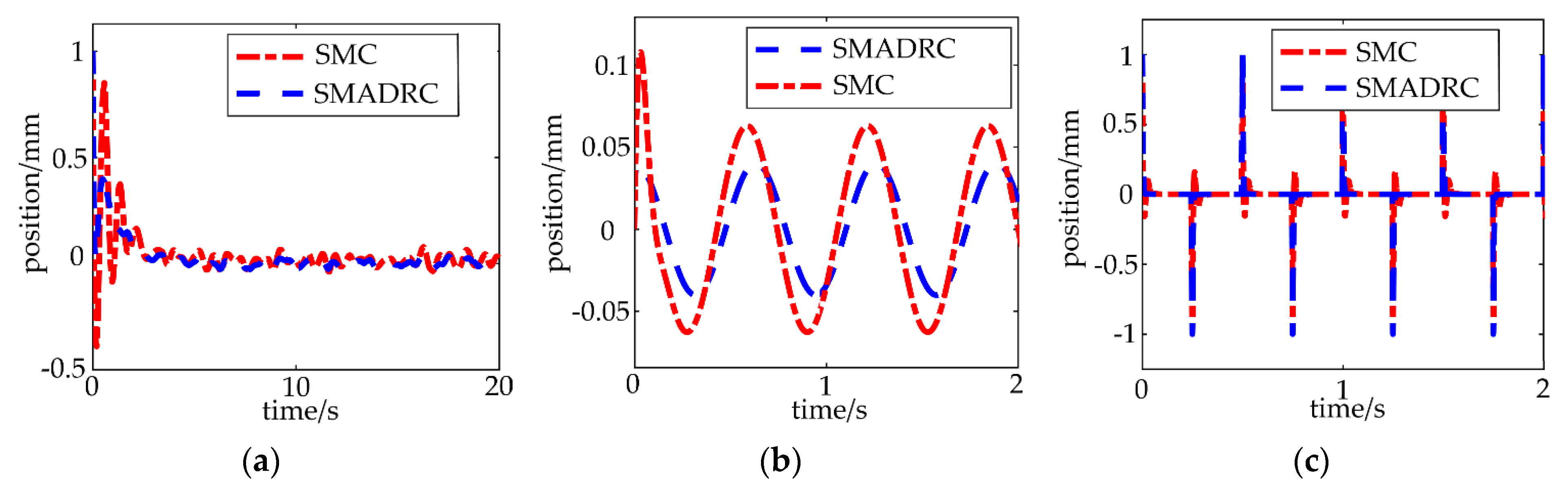
The proposed sliding-mode active disturbance rejection control can ensure smaller tracking errors and faster tracking speed than the sliding-mode control in the pre-control period (best for the signal tracking, the first 0.5 s) and without jitter.
(2)
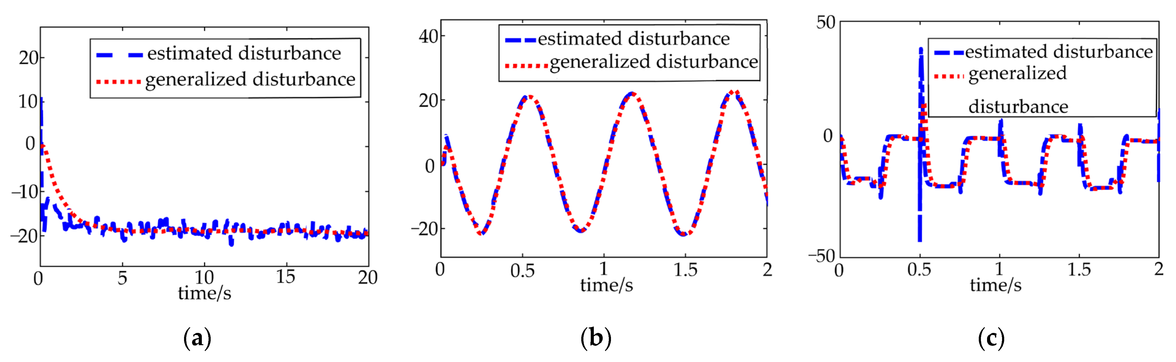
The proposed sliding-mode active disturbance rejection control has better robustness. Using the designed observer, the unmolded dynamic and environmental disturbances are estimated and compensated, which can reduce the impact of disturbances on the control process and improve the control accuracy.

Author Contributions

Conceptualization, methodology, and writing A.Z.; software, validation, and writing—original draft preparation, J.S.; supervision, L.L. All authors have read and agreed to the published version of the manuscript.

Funding

This research was funded by the Natural Science Foundation of Shanghai in 2021, grant number 21ZR1426000, and 2021 Open Fund of Shanghai Large Component Intelligent Manufacturing Robot Technology Collaborative Innovation Center, grant number ZXP20211101.

Institutional Review Board Statement

Not applicable.

Informed Consent Statement

Not applicable.

Data Availability Statement

Not available.

Conflicts of Interest

The authors declare no conflict of interest.

References

  1. Shi, B.C.; Shi, R.; Wang, F.J. Design of an adaptive feedforward/feedback combined control for piezoelectric actuated micro positioning stage. Precis. Eng. J. Int. Soc. Precis. Eng. Nanotechnol. 2022, 78, 199–205. [Google Scholar] [CrossRef]
  2. Liao, S.F.; Ding, B.X.; Li, Y.M. Design, Assembly, and Simulation of Flexure-Based Modular Micro-Positioning Stages. Machines 2022, 10, 421. [Google Scholar] [CrossRef]
  3. Fan, X.G.; Zhi, Y.L.; Liao, C.; Shen, J.; Wang, X. A Nano Positioning Platform for STM and Its Compound Control Algorithm. IEEE Trans. Instrum. Meas. 2022, 71, 1–9. [Google Scholar] [CrossRef]
  4. Sun, F.; Hao, Y.; Xu, F.; Jin, J.; Li, Q.; Tong, L.; Zhang, M.; Zhang, X. Proposal of an Equal-Stiffness and Equal-Stroke 2D Micro-Positioning Platform Driven by Piezoelectric Actuators. Actuators 2020, 9, 47. [Google Scholar] [CrossRef]
  5. Wu, H.; Lai, L.; Zhang, L.; Zhu, L. Fractional order zero phase error tracking control of a novel decoupled 2-DOF compliant micro-positioning stage. J. Micromechanics Microengineering 2021, 31, 105006. [Google Scholar] [CrossRef]
  6. Zou, H.; Ding, Y.; Zhang, J.; Cai, A.; Zhang, X.; Zhou, Y. Precise geometric error model based on z-axis motion platform of micro v-groove machine tools. Int. J. Adv. Manuf. Technol. 2017, 92, 3219–3224. [Google Scholar] [CrossRef]
  7. Hakjun, L.; Dahoon, A. Ultra-precision Magnetic Levitation Stage Utilizing Voice Coil Motors. J. Korean Soc. Manuf. Technol. Eng. 2022, 31, 77–85. [Google Scholar]
  8. Lyu, Z.K.; Xu, Q.S. Design of a New Bio-Inspired Dual-Axis Compliant Micromanipulator with Millimeter Strokes. IEEE Trans. Robot. 2022, 1–15. [Google Scholar] [CrossRef]
  9. Zhang, X.; Lai, L.J. Closed-loop inverse iterative learning control in frequency-domain for electromagnetic driven compliant micro-positioning platform. Opt. Precis. Eng. 2021, 29, 2149–2157. [Google Scholar] [CrossRef]
  10. Gu, G.Y.; Zhu, L.M.; Su, C.Y.; Ding, H.; Fatikow, S. Proxy-Based Sliding-Mode Tracking Control of Piezoelectric-Actuated Nanopositioning Stages. IEEE-ASME Trans. Mechatron. 2015, 20, 1956–1965. [Google Scholar] [CrossRef]
  11. Yang, C.H.; Wang, K.C.; Wu, L. Positional Regulation of Electrostatic Micro-electromechanical Actuator via Adaptive Two-stage Sliding Mode Control. Sens. Mater. 2020, 32, 3343–3354. [Google Scholar] [CrossRef]
  12. Chen, X.; Liu, Y.; Zhang, L.; Gao, J.; Yang, B.; Chen, X. Event-Triggered Adaptive Control Design with Prescribed Performance for Macro-Micro Composite Positioning Stage. IEEE Trans. Ind. Electron. 2021, 68, 9963–9971. [Google Scholar] [CrossRef]
  13. Kato, M.; Hirata, K.; Asai, Y. Experimental verification of disturbance compensation control of linear resonant actuator. Int. J. Appl. Electromagn. Mech. 2016, 52, 1637–1646. [Google Scholar] [CrossRef] [Green Version]
  14. Seok, J.K.; Kim, S.K. VCM controller design with enhanced disturbance decoupling for precise automated manufacturing processes. IET Electr. Power Appl. 2012, 6, 575–582. [Google Scholar] [CrossRef]
  15. Shi, X.X.; Chen, Y.Q. Extended state observer design with fractional order Bode′s ideal cut-off filter in a linear motor motion control system. Proc. Inst. Mech. Eng. Part I J. Syst. Control. Eng. 2022. [Google Scholar] [CrossRef]
  16. Zhi, L.; Huang, M.; Han, W.; Wang, Z.; Lu, X.; Bai, Y.; Gao, H. Improved Active Disturbance Rejection Double Closed-Loop Control of a Rotary-Type VCM in a Moving Mirror Control System. Sensors 2022, 22, 3897. [Google Scholar] [CrossRef] [PubMed]
  17. Feng, W.D.; Bai, J.; Zhang, J. Full-order adaptive observer for interior permanent-magnet synchronous motor based on novel fast super-twisting algorithm. Meas. Control. 2022, 00202940221122235. [Google Scholar] [CrossRef]
  18. Du, Y.W.; Cao, W.H.; She, J.H. Analysis and Design of Active Disturbance Rejection Control with an Improved Extended State Observer for Systems with Measurement Noise. IEEE Trans. Ind. Electron. 2023, 70, 855–865. [Google Scholar] [CrossRef]
  19. Wang, F.; Cheng, T.; Zhu, H.; Liu, Z.; Han, C.; Wang, R.; Liu, E. Modified active disturbance rejection control scheme with sliding mode compensation for airborne star tracker driven by Permanent Magnet Synchronous Motor. Control. Eng. Pract. 2022, 127, 105267. [Google Scholar] [CrossRef]
  20. Zhang, Z.; Guo, Y.; Gong, D.; Liu, J. Global Integral Sliding-Mode Control with Improved Nonlinear Extended State Observer for Rotary Tracking of a Hydraulic Roof bolter. IEEE/ASME Trans. Mechatron. 2022, 1–12. [Google Scholar] [CrossRef]
  21. Lin, P.; Zhang, S.; Wu, Z.; Li, J.; Sun, X.M. A Linear-Nonlinear Switching Active Disturbance Rejection Voltage Controller of PMSG. arXiv 2020, arXiv:2010.09295. [Google Scholar] [CrossRef]
  22. Shang, Y.; Li, Y.; Zhao, C. Motion Control of Autonomous Underwater Glider with Sliding Variable Structure Control. In International Conference on Autonomous Unmanned Systems; Springer: Singapore, 2022; pp. 1484–1494. [Google Scholar] [CrossRef]
  23. Chang, Y.; Tian, W.; Jin, G.; Chen, E.; Li, S. Active control of nonlinear suspension with fractional order based on a differential geometry method. J. Vib. Shock. 2022, 40, 270–276. [Google Scholar] [CrossRef]
  24. Qiu, Z.; Duan, C.; Yao, W.; Zeng, P.; Jiang, L. Adaptive Lyapunov Function Method for Power System Transient Stability Analysis; Institute of Electrical and Electronics Engineers Inc.: Piscataway, NJ, USA, 2022; pp. 1–14. [Google Scholar] [CrossRef]
Figure 1. The micro-positioning platform.
Applsci 13 01309 g001
Figure 2. The control structure diagram.
Applsci 13 01309 g002
Figure 3. Trajectory tracking variation under the different controllers. (a) Step signal trajectory tracking, (b) sign signal trajectory tracking, (c) square wave signal trajectory tracking.
Applsci 13 01309 g003
Figure 4. The tracking errors variation under the different controllers, (a) Tracking error of step signals, (b) Tracking error of sign signals, (c) Tracking error of square wave signals.
Applsci 13 01309 g004
Figure 5. The perturbation estimation under the different tracking, (a) the perturbation estimation under the step signals, (b) the perturbation estimation under the sign signals, (c) the perturbation estimation under the square wave signals.
Applsci 13 01309 g005
Disclaimer/Publisher’s Note: The statements, opinions and data contained in all publications are solely those of the individual author(s) and contributor(s) and not of MDPI and/or the editor(s). MDPI and/or the editor(s) disclaim responsibility for any injury to people or property resulting from any ideas, methods, instructions or products referred to in the content.

