Featured Application
This work is aimed at carrying out calculations of strengthening of reinforced concrete structures on the shear, taking into account a new factor—the loading level at which strengthening occurs. Its application field is strengthening of reinforced concrete bent structures with composite materials on the shear.
Abstract
This article presents research on the bearing capacity and methods of calculating reinforced concrete beams on the shear without internal shear reinforcement, which are strengthened with a composite FRCM system. The test samples were divided into two series: the first series—control, in which the variable parameter was the shear span (a/d = 2, a/d = 1.5, and a/d = 1); and the second series—reinforced by the FRCM system, without load, and strengthened at different load levels. The method of calculating experimental beams was tested according to the current code and data from the fib report. In this article, recommendations for determining the angle of inclined struts θ, the coefficient of the concrete shear strength CRd,c, and the coefficient of the load level at which strengthening is performed are proposed. The calculation with the these recommendations showed a good convergence of experimental and theoretical data in the 16–29% range, which is a much higher convergence than the calculation without these recommendations.
1. Introduction
The study of the bearing capacity of reinforced concrete (RC) elements on the shear is essential due to the complex stress–strain state. In codes [1,2,3], shear designs are calculated with a significant margin of strength, leading to excessive overspending on materials. The development and implementation of dependencies that can realistically assess the bearing capacity of RC beams on the shear that need strengthening are essential tasks for scientists. The presented experimental and theoretical research is based on the existing methodology for calculating current codes [3].
2. Analysis of Previous Research
The main reasons for the need to strengthen structures are a decrease in their bearing capacity or the need to increase their bearing capacity to manage a greater load.
Defects occur in all structures during operation, and reduce the bearing capacity of RC structures. Most common are concrete defects in reinforced concrete beams [4] or columns [5]. The defects described in these works lead to a significant decrease in the bearing capacity of such structures.
One of the reasons for the rapid spread of defects is the opening of cracks in the RC structure. In the study [6], it was established that the load level of the opening shear crack was 53% higher than the load level of the appearing bending cracks. This dependence was derived for prestressed reinforced concrete T-beams based on experimental data. An empirical expression for determining the projection of a dangerous shear crack and the necessary shear reinforcement has been obtained. The use of modern methods and devices for viewing and detecting cracks allows faster identification of their effects on the safe operation of structures with higher accuracy [7].
In the case of emergency dynamic loads, it is also important to research the shear crack resistance of concrete and the reinforced concrete elements of protective structures. The work [8] describes the influence of dynamic loads on protective structures, data about changing the shear crack resistance, and the calculation principles in this case.
The appearance of corrosion or mounting holes in the structure decreases the strength of RC beams. In this regard, experimental research was conducted focused on different RC beams with a web opening, such as beams made from ultra-high-performance concrete (UHPC) with a web opening in the support area [9].
Developing methods for strengthening RC structures requires the improvement of calculation methodologies. To determine the necessary amount of reinforcement for structures, their residual bearing capacity needs to be known [10,11]. Only by having the exact value of the residual strength is it possible to design economic strengthening of structures.
Today, structures often need to be strengthened due to the demand to restore or increase the bearing capacity of elements. Classic methods of strengthening are improving and changing. For example, geopolymer concrete (GPC) is used with improved properties for jacketing [12]. In this case, there is a need to perform experimental investigations and improve the calculation methodology.
The most effective way to increase the bearing capacity of bent elements is to strengthen the compressed zone of concrete and tensile reinforcement [13]. Strengthening was performed by using fine-grained or steel fiber concrete in the compressed area and glued carbon fibers in the tensile area. The overall strengthening effect was 32–69%, depending on the type of strengthening and the type of load (one-time or low-cycle).
A study of various types of composites (Fiber-Reinforced Polymer (FRP) and Fiber-Reinforced Cementitious Matrix (FRCM)) as systems for strengthening shear beams was conducted in the article [14]. It was established that the beams strengthened by the FRCM system showed a worse interaction than the samples strengthened by the FRP system.
Research on the implementation of U wraps of the FRCM system is relevant [15]. In this case, the possibility of the practical application of such strengthening increases. Strengthening took place along the entire length of the beam and was performed in one or more layers. The reinforcement effect ranged from 21 to 56%, depending on the characteristics of the concrete and the number of layers of reinforcement material.
The influence of the reinforcement numbers at different reinforcement ratios for longitudinal reinforcement for strengthened concrete beams by the FRP system showed the necessity to consider the specified reinforcement ratio and the importance of the quality performance of design works [16].
The combination of different types of strengthening to increase the bearing capacity has been used more and more widely [17]. Experimental studies of two-span RC beams with strengthening frames from rebars and concrete with steel fibers have been conducted. Research [18] proposed a method of strengthening the concrete properties by laying a fibrous mesh in the top (mortar) layer of the concrete surface. Basalt fiber, aramid fiber, and carbon fiber mesh were selected as reinforcing materials to study the concrete’s early cracking resistance and the mortar’s early cracking characteristics. Another method is installing a polymer–cement coating on wall structures [19]. The influence on the durability and destruction of the tested wall elements was described.
The need for reinforcement often arises in connection with an increase in the seismicity of the building or a change in code [20]. Research into reinforced concrete beams with different schemes and reinforcement principles for seismic impact is directed toward the most effective construction of RC beams.
A particular type of strengthening increases the seismic resistance of the joints of reinforced concrete structures. A promising direction is their reinforcement with composite materials with significant strength and deformability, which can prevent the destruction and collapse of structures [21].
Long-term effects on structures also lead to the need to strengthen them [22]. As the service life increases, the mechanical characteristics deteriorate due to the properties of filled concrete that wear out over time. Another factor that is rarely taken into account is the level of load on the structure for which strengthening is performed [23].
An important aspect of the development of methods of strengthening reinforced concrete structures is their practical application, such as the strengthening of an RC tank [24]. According to results of a technical inspection, numerous defects were discovered, and a method of using steel external bandages was developed. However, to restore tightness and improve operational characteristics by installing reinforced concrete brackets [25]. The given examples of strengthening were carried out taking into account the existing defects and the real state of the structure.
Expanding the application areas of FRCM systems requires appropriate design models. The paper [26] proposes a simplified modified compression field theory (SMCFT) for shear model calculation. According to this calculation model, the calculation accuracy was 0.96 (the ratio of theoretical data to experimental data) with a deviation of 0.14.
The calculation of strengthening concrete T-beams reinforced in shear with FRCM composites based on the ACI549.4R-13 code is relevant [27]. The results of the calculations were significantly underestimated and require further refinement.
For a high-quality calculation of RC structures, it is necessary to consider the nonlinear properties of materials and the deformation criteria for the exhaustion of the bearing capacity [28]. The same requirements apply to the calculation of constructions on the shear. The proposed method for determining the reliability of RC structures on shear allows optimal design decisions to be made, ensuring the specified level of construction reliability without overspending on materials [29]. Optimizing the design method is an urgent issue. This technique can be based on geometric parameters and structural features of systems [30]. This technique can be based on design features and systems’ geometric parameters. Required reinforcements for beams with span-to-depth ratios varying from 10 to 20 were first determined in accordance with Eurocode 2. A probabilistic analysis using Monte Carlo simulations then revealed that doubling the span-to-depth ratio would not worsen the performance of the beams in terms of ultimate strength [31].
One of the effective methods of strengthening structures is their unification of prefabricated individual elements into a continuous spatial structure [32]. The model for determining the shear strength of such combined reinforced concrete beams was proposed on the basis of experimental and calculation data.
An important aspect of the FRCM application of strengthening systems is studying their carrying capacity under the influence of high temperatures [33]. It was established that heating/cooling down cycles affect the bearing capacity of FRCM systems for reinforcing reinforced concrete structures. However, it should be noted that according to an investigation of reinforced concrete beams on the FRCM (TRP) section, the systems showed better resistance to temperature effects than the FRP systems [34].
Based on the above studies, the findings do not consider the load level at which the stress-deformed state of structures changes (strengthening and/or damaging). Moreover, applying structural design models in practice is difficult since regulatory documents do not support them. This study proposes the calculation of reinforced concrete beams on the shear, without internal steel shear reinforcement, strengthened with a composite material based on the current code, considering the load level at which the reinforcement will be performed.
3. Experimental Data
In this research work, six test samples were tested. The initial dimensions of the sample’s cross-section was 200 × 100, and the length was 2100 mm, but the actual dimensions had minor deviations (Table 1). Beams were reinforced with tensile reinforcement 2 Ø18 A500C, and compressed—2Ø10A500C. They were without transverse reinforcement in the supporting areas. The concrete for all beams was the same—C32/40.

Table 1.
Bearing capacity on the shear without transverse reinforcement.
Three beams were tested as control samples in the first research stage. The variable parameter was the shear span, which acquired the following values: a/d = 1, a/d = 1.5, and a/d = 2. The criterion for exhausting the bearing capacity was obtaining limit values of the strains of compressed concrete area in the zone above the diagonal (inclined or shear) crack [1]. Each support area was tested separately, according to the developed testing methodology [35].
Exhaustion of the bearing capacity on the shear was equated to the physical destruction of the concrete compressed area. The occurrence of the limit state of control samples occurred in the following sequence:
- opening of a shear crack of maximum width (acrc = 0.4 mm) on the concrete surface;
- cracking of the compressed area concrete and plastic deformation of the rebars of the reinforcing frame took place (Figure 1).
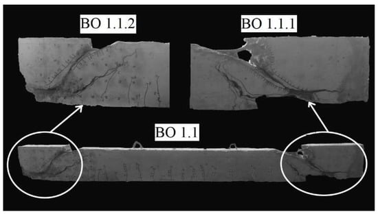 Figure 1. Tested control samples without internal shear reinforcement.
 - shear reinforcement.
Test results of the bearing capacity on the shear without transverse reinforcement are described in Table 1.
According to them, the increase in bearing capacity on the shear was recorded at 1.48 times when the shear span was reduced from a/d = 2 to a/d = 1.5. When the shear span was a/d = 1, it increased 2.08 times. This effect is shown when the shear span is reduced, the compressive forces increase in the support zone, which are effectively absorbed by the concrete.
In the second stage, reinforced concrete beams were reinforced by sticking P.B.O. fabric in the form of vertical strips with a width of 70 mm for the possibility of fixing concrete strains in the support areas (Figure 2). Beams were tested according to the following program: BS 1.1–0, strengthened without initial load; BS 1.2–0.3 and BS 1.3–0.5—at the initial load level equal to 0.3 and 0.5 from the destructive one determined by experimental tests of unreinforced samples. The criterion for exhausting bearing capacity was adopted from unreinforced samples: the exhaustion of the shear strength was equated to the physical destruction of the compressed concrete area of the samples.
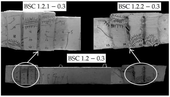
Figure 2.
General view of exhausted shear strength of reinforced samples.
The collapsing of an RC beam reinforced with a composite fabric on the shear occurred in the following sequence:
- opening of a diagonal crack of maximum width (acrc = 0.4 mm) on the concrete surface;
- propagation of the diagonal crack to the concrete compressed area. The appearance of a network of cracks with an opening width of acrc = 0.2 mm on the surface of the strengthening system;
- collapse of concrete in the zone of action of the main tensile stresses; detachment of the reinforcement system in this area;
- plastic deformation of reinforcing bars. Destruction of the concrete compressed area and significant deformations of the reinforcing fabric can be seen due to the violation of the protective layer.
When the load was further increased, the ends of the fabric tape completely peeled off, and their anchoring failed. The exhaustion of the bearing capacity occurred at the moment of exfoliation of the concrete compressed area, together with the sharp elongation of the tape and the damage of the cover of the FRCM system in the area of propagation of the inclined crack (Figure 2).
The increase in the bearing capacity of the strengthened RC beams on the shear is given in Table 2.

Table 2.
Bearing capacity of strengthened research samples on the shear without internal transverse reinforcement.
The maximum effect of increasing the bearing capacity was 45% for samples reinforced without an initial load. Accordingly, as the initial load increased, the strengthening effect decreased. For a beam strengthened at the level of 0.3∙, the strengthening effect was 21%, and for BS 1.3–0.5—16%. Increasing the load level to a higher value did not occur because the strengthening effect would have decreased even more, and it can be taken as a research deviation. The maximum strengthening effect is commensurate with the increase in the shear bearing capacity when the shear span is reduced from a/d = 2 to a/d = 1.5 (see Table 1).
For more details, experimental investigations of strengthened and unstrengthened RC beams on the shear are given in the articles [36,37].
4. Calculation Model for Determining the Shear Strength of the Tested Samples
4.1. Methodology of Calculating Shear Strength of the Control RC Beams
For a long time in Eastern Europe, codes [38] allowed the calculation of the bearing capacity on the shear according to the engineering method. Figure 3 shows the distribution of forces in the calculation scheme from the distributed load q (or equivalent action F) and the occurrence of forces in concrete Qb and transverse reinforcement RswAsw, which is located with step s. The bearing capacity of such an element is considered at the section on the length of the projection of a diagonal crack on the longitudinal axis (c—length for reinforcement, c0—for concrete).
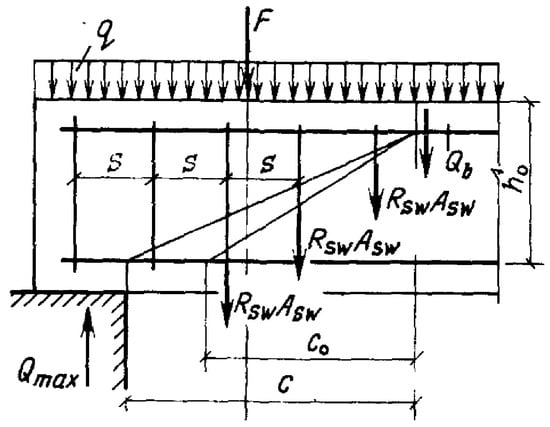
Figure 3.
Scheme of the shear forces when calculating according to the engineering method [38].
The engineering method is based on the equilibrium of limit forces. The basis is the determination of the actual internal forces in the support section and their comparison with the external acting loads.
The calculation of RC elements for the action of the transverse force was carried out under the condition:
This relationship determines the total shear force as the sum of the strength of shear reinforcement and the concrete shear strength that can be borne by the support section. Since there is no transverse reinforcement in the samples, condition (1) takes the form:
The shear force perceived by concrete was calculated based on the following:
However, if the value is not less than:
—coefficient that takes into account the influence of the type of concrete (light or heavy); —a coefficient that takes into account the influence of compressed flanges in T-shaped and I-shaped elements (accepted no more than 0.5); —a coefficient that takes into account the influence of longitudinal compressive forces; —the length of the projection of the most dangerous inclined section on the longitudinal axis of the element, cm; —respectively, the width and effective depth of the section, cm; —design value of concrete axial tensile strength, MPa.
Current codes [1,2,3] regulate shear strength calculation according to the “truss model”. The bearing capacity in the zone of action of the transverse force, where is no shear reinforcement, is considered the strength of the concrete in a section at an angle of 45°.
The shear strength of reinforced concrete beams, according to current standards [1,3], is considered similar to condition (2):
—the calculated value of the transverse force from the external load. This is the value of the transverse force that a support area can absorb without transverse rebar and prestressed longitudinal reinforcement or axial force, according to the codes [2,3], is determined by the dependence:
However, if the value is not less than:
—concrete shear strength [39], codes [2,3] recommend taking 0.18; —coefficient, which takes into account the influence of the beam cross-section depth; —reinforcement ratio for longitudinal reinforcement; —cross-sectional area of tensile reinforcement, mm2; —characteristic value of concrete compressive strength at the age of 28 days, MPa; —respectively, the smallest width of the cross-section in the tensile area and the effective depth of the cross-section, mm; —the minimum value of the shear strength that can lead to failure before yielding occurs in the longitudinal reinforcement, MPa.
Longitudinal reinforcement was taken into account in the calculation only if it was installed at a distance beyond the projection of the calculated section at an angle of 45°. In this case, —the minimum required anchoring length of longitudinal reinforcement (Figure 4).
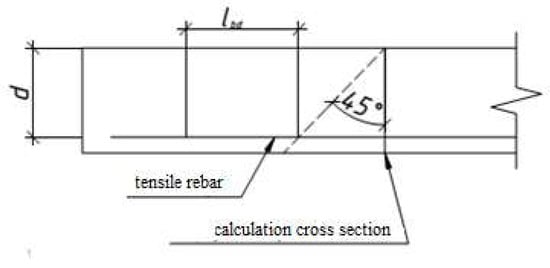
Figure 4.
A model of the influencing factors on the shear strength of a support area [2,3].
The coefficient β is equal to when loading the design elements from above within limits (Figure 5) as a reducing coefficient of the shear force. In this model, it is proposed to consider it in the calculation by dividing the determined bearing capacity by this coefficient.
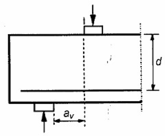
Figure 5.
Case of applying load for the coefficient β [2,3].
When using the coefficient β, the following condition must be met:
—design value of concrete compressive strength, MPa; —coefficient of reduction shear strength of cracked concrete. It is recommended to determine the coefficient according to the dependence [3]:
Make calculations of the control samples according to the above dependencies. For convenience, we summarize the main calculation parameters in Table 3.

Table 3.
Basic calculation parameters of beams without transverse reinforcement.
The results of the calculation are given in the Table 4.

Table 4.
The results of determining bearing capacity on the shear without transverse reinforcement.
According to the engineering method, the calculation showed convergence within 32–46% in the direction of exaggeration of experimental results. Such an indicator is a satisfactory result, considering the complex stress–strain state, lacking influence of longitudinal reinforcement in the methodology, and the suddenness and speed of exhaustion of the bearing capacity on the shear.
The overestimation of experimental data compared to calculation ones determined according to the current code is much greater. Considering the progress of the calculation, it can be established that all values, except for one, change during the calculation process. Only the value of CRd,c (shear strength of concrete [39]) was constant in all calculations and was 0.18 MPa. This value is accepted as a minimum and does not depend on the change in concrete class. To determine the influence of the shear strength of concrete on the bearing capacity on the shear, it is suggested to use relationship from European codes of the 1997 edition, which considers changing the concrete shear strength from tension strength [40]:
When designing RC structures, the compressive strength of concrete is used more often. Therefore, we switch from the concrete tensile strength to the compressive in the dependence (10), using the relationship given in the same standards:
By substituting dependencies (11) and (12) into the relationship (10), we obtain the equation for determining the shear strength of concrete from the concrete compressive strength:
After substituting the obtained values into dependence (6), we recalculate the shear strength of the control beams (Table 5).

Table 5.
The bearing capacity of the control beams on the shear without transverse reinforcement.
Comparisons of the results of theoretical and experimental studies are presented graphically in Figure 6.
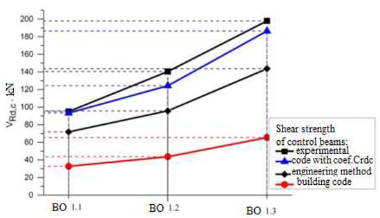
Figure 6.
Experimental and theoretical data of the shear strength for control samples.
The results of determining the shear strength of the RC beams using the updated values of CRd,c, defined by the formula (13), showed a much higher convergence of results. Experimental data exceed theoretical calculation results by 16–29%., which is acceptable given the sharp nature of the destruction of such elements without transverse reinforcement.
4.2. Methodology of Calculating Shear Strength of the Strengthened RC Beams by FRCM System
The bearing capacity of the RC beams on the shear, which is strengthened with composite system in the form of fabric strips, is calculated according to the method of the truss analogy [2,3]. It is calculated based on the condition that the shear force is perceived only by the shear reinforcement. In this case, the stressed–strained state of the support area is considered by the truss analogy (Figure 7). The concrete compressed zone is taken as a top, compressed chord (Figure 7A), and the working tensile reinforcement, respectively, as a bottom, tensile truss chord (Figure 7C). In this case, compressed struts of the webs are reduced to compressed strips of concrete in the support area of the beams (Figure 7B), while tensile struts of the web—shear reinforcement (Figure 7D).
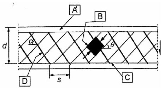
Figure 7.
Truss model of the calculation state in the supporting area of RC beam [2]: A—compressed chord; B—compressed struts; C—tensile truss chord; D—tensile struts.
In Ukraine, codes do not allow the design of reinforced concrete elements strengthened with composite materials. Therefore, to calculate the bearing capacity on the shear, we accept the following prerequisites for the operation:
- -
- there is a valid hypothesis of flat sections for the supporting areas;
- -
- reinforcement with composite material works as additional external reinforcement;
- -
- the reinforcement system works together with the concrete in the support area.
In this way, the external composite reinforcement is included in the design model, as with tensile elements of the truss web.
Provided that the accepted prerequisites are correct, it is proposed to calculate the shear strength of the strengthening element, such as internal shear reinforcement. Therefore, to calculate the shear strength of the strengthening system, we use an equation from codes [2,3], substituting the parameters of the composite fabric:
Afw = (0.00455 × 7) × 2 = 0.0637 mm2—cross-sectional area of the composite fabric; sf = 100 mm—step of strengthening elements.
The angle θ was determined along the diagonal crack in which the destruction of the element took place. However, it should be noted that the angle of inclined struts extends from the point of the center of force applied to the face of the element’s support (Figure 8).

Figure 8.
Location of the inclined struts [41].
With the determined bearing capacity of the additional reinforcement, the angle of inclined struts was 21.8°, which was defined from experimental data (Figure 9). The obtained value of the angle of inclination corresponds to the maximum value from the code cotθ = 2.5 [2,3].
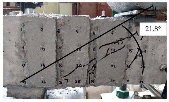
Figure 9.
The angle of inclined struts in the sample BS 1.1.1–0.
The calculated shear strength of the composite reinforcement was determined by relationship (15), taking into account the calculation recommendations given in the report [42]:
—design value of limit strains for composite reinforcement; —characteristic value of limit strains for composite reinforcement; —partial factor by material, according to recommendations [42], which is accepted when there is a possibility of slipping through the fabric or if there is a possibility of tissue rupture (or the coefficient is taken equal to 1 in the case of the impossibility of the above-described conditions); —reducing coefficient showing the dependence of the shear strength to the tensile strength of the reinforcement, described in the code [2] and Fib recommendations [42]; —the design value of the modulus of elasticity of the composite material, which is taken at the level of 40% of the characteristic value. According to Fib recommendations [38], the joint operation of concrete and reinforcement elements occurs only with such an underestimation of the characteristic value of the composite material modulus of elasticity.
To take into account the load level of the beam at which the strengthening took place, it is proposed to use a coefficient that depends on the carrying capacity of the beam for shear strength and the load level. For the load factor of the element, it is suggested to use the dependence:
—external transverse force; —design value of the shear strength of the RC beams; n—the index, which considered influencing from internal steel reinforcement (3/2—for a support area without transverse reinforcement; 1/2—for a support area with transverse reinforcement).
The bearing capacity is proposed to be calculated as the sum of the concrete and reinforcement composite system shear strength. This principle is proposed in Formula (1) [38], in Section 4.1 described above.
Based on the described Equations (6), (14), and (16), the following dependence of determining the shear strength of the RC bent elements without transverse (shear) reinforcement strengthened with composite fabric under action of the load was obtained:
Analogous expressions are proposed for providing the shear strength strengthened with composite materials by many researchers and are given in Fib recommendations [42].
The above expressions were tested to calculate the bearing capacity of tested samples without internal transverse reinforcement. The value of the shear strength of the control samples is determined according to the current code, and consider the refined value CRd,c determined according to Equation (13). Result of the theoretical calculation data is shown in the Table 6.

Table 6.
Comparison theoretical and experimental data of the shear strength of the tested RC beams without transverse reinforcement strengthened with a composite system.
Additionally, the obtained results are shown as curves in Figure 10.
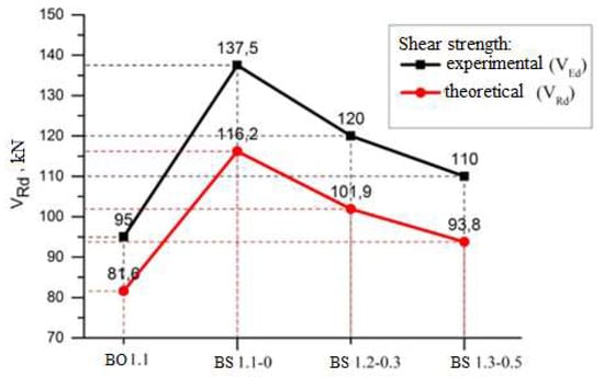
Figure 10.
Comparison theoretical and experimental results of shear strength of strengthened beams.
Satisfactory convergence of results was obtained for all experimental samples, within 16–18% in the direction of overstatement of experimental data. The calculation shear strength of the composite material as a transverse reinforcement, taking into account the proposed coefficient, shows a satisfactory convergence, namely an overestimation of the experimental data by 23% for all investigated levels of the active load.
5. Conclusions
The calculation of the bearing capacity of the RC beams on the shear was tested according to the current codes with clarifications regarding the consideration of the concrete shear strength CRd,c. The calculation results showed a better convergence; the deviation was 16–29% in the direction of the experimental data exceeding the theoretical.
An improved methodology for calculating the bearing capacity of reinforced concrete beams without shear reinforcement strengthened with a composite FRCM system is proposed. This methodology includes the following:
- -
- application of compatible bearing capacity of concrete and external reinforcement;
- -
- taking into account the angle of the inclined struts θ;
- -
- principles for calculating the external composite reinforcement are proposed, which are based on FIB recommendations and existing design code;
- -
- the proposed coefficient takes into account the reduction in the use of composite reinforcement depending on the initial load level of the beam.
The proposed method allows the determination of the actual additional carrying capacity of the reinforcement system. A new coefficient is proposed that considers the change in the load level and, accordingly, the change in the reinforcement effect. Approbation of the proposed methodology for calculating strengthened samples without internal transverse reinforcement showed a good convergence of 23%. This methodology can be simply applied in practical design.
Author Contributions
Conceptualization Z.K.; methodology, Z.K., Z.B. and I.G.; validation, Z.B., P.V. and I.G.; formal analysis, P.V. and I.G.; resources, I.G. and P.V.; data curation, Z.K. and Z.B.; writing—original draft preparation, P.V., I.G. and Z.B.; writing—review and editing, Z.K. and I.G.; visualization, P.V. and I.G.; supervision, Z.K. and Z.B.; project administration, Z.K. and Z.B.; funding acquisition, Z.K. All authors have read and agreed to the published version of the manuscript.
Funding
This research received no external funding.
Institutional Review Board Statement
Not applicable.
Informed Consent Statement
Not applicable.
Data Availability Statement
Publicly available datasets were analyzed in this study. This data can be found here: https://www.researchgate.net/profile/Pavlo-Vegera.
Conflicts of Interest
The authors declare no conflict of interest.
References
- DBN V.2.6-98:2009; Concrete and Reinforced Concrete Structures. Ministry of Regional Construction: Kyiv, Ukraine, 2011. (In Ukrainian)
- DSTU B.V.2.6-156:2010; Concrete and Reinforced Concrete from Heavy Concrete. Ministry of Regional Construction: Kyiv, Ukraine, 2011. (In Ukrainian)
- EN 1992-1-1; Eurocode 2: Design of Concrete Structures—Part 1-1: General Rules for Buildings. European Committee for Standartization: Brussels, Belgium, 2004.
- Lobodanov, M.; Vegera, P.; Khmil, R.; Blikharskyy, Z. Influence of damages in the compressed zone on bearing capacity of reinforced concrete beams. Lect. Notes Civ. Eng. 2021, 100, 260–267. [Google Scholar]
- Klymenko, Y.; Grynyova, I.; Kos, Z.; Maksiuta, O. Method for Determining the Residual Bearing Capacity of Damaged I-Beam Reinforced Concrete Columns. Lect. Notes Civ. Eng. 2022, 290, 171–184. [Google Scholar]
- Karpiuk, V.; Somina, Y.; Karpiuk, F.; Karpiuk, I. Peculiar aspects of cracking in prestressed reinforced concrete T-beams. Acta Polytech. 2021, 61, 633–643. [Google Scholar] [CrossRef]
- Ge, Y.; Liu, J.; Zhang, X.; Tang, H.; Xia, X. Automated Detection and Characterization of Cracks on Concrete Using Laser Scanning. J. Infrastruct. Syst. 2023, 29, 04023005. [Google Scholar] [CrossRef]
- Karkhut, I. Improving the crack resistance of inclined cross-sections of reinforced concrete containment shells in areas of emergency loads of pushing. East.-Eur. J. Enterp. Technol. 2022, 4, 31–41. [Google Scholar]
- Elsayed, M.; Badawy, S.; Tayeh, B.A.; Elymany, M.; Salem, M.; ElGawady, M. Shear behaviour of ultra-high performance concrete beams with openings. Structures 2022, 43, 546–558. [Google Scholar] [CrossRef]
- Blikharskyy, Z.; Lobodanov, M.; Vegera, P. Investigation of defective reinforced concrete beams with obtained damage of compressed area of concrete. Prod. Eng. Arch. 2022, 28, 225–232. [Google Scholar] [CrossRef]
- Kos, Z.; Klymenko, Y.; Crnoja, A.; Grynyova, I. Calculation Model for Estimation of Residual Bearing Capacity of Damaged Reinforced Concrete Slender Columns. Appl. Sci. 2022, 12, 7430. [Google Scholar] [CrossRef]
- Sudha, C.; Sambasivan, A.K.; Kannan Rajkumar, P.R.; Jegan, M. Investigation on the performance of reinforced concrete columns jacketed by conventional concrete and geopolymer concrete. Eng. Sci. Technol. Int. J. 2022, 36, 101275. [Google Scholar]
- Borysiuk, O.; Ziatiuk, Y. Experimental research results of the bearing capacity of the reinforced concrete beams strengthened in the compressed and tensile zones. Lect. Notes Civ. Eng. 2020, 100, 63–70. [Google Scholar]
- Gonzalez-Libreros, J.H.; Sneed, L.H.; D’Antino, T.; Pellegrino, C. Behavior of RC beams strengthened in shear with FRP and FRCM composites. Eng. Struct. 2017, 150, 830–842. [Google Scholar] [CrossRef]
- Loreto, G.; Babaeidarabad, S.; Leardini, L.; Nanni, A. RC beams shear-strengthened with fabric-reinforced-cementitious-matrix (FRCM) composite. Int. J. Adv. Struct. Eng. 2015, 7, 341–352. [Google Scholar] [CrossRef]
- Sabzi, J.; Esfahani, M.R.; Ramezani, A. The effect of tensile reinforcement on the behavior of CFRP strengthened reinforced concrete beams: An experimental and analytical study. Steel Compos. Struct. 2023, 46, 115–132. [Google Scholar]
- Babych, Y.M.; Savitskiy, V.V.; Andriichuk, O.V.; Ninichuk, M.V.; Kysliuk, D.Y. Results of experimental research of deformability and crack-resistance of two span continuous reinforced concrete beams with combined reinforcement. Mater. Sci. Eng. 2019, 708, 012043. [Google Scholar] [CrossRef]
- Li, Y.; Xu, W.; Zhang, J.; Fan, J.; Gao, P.; Hu, C. Early cracking characteristics of concrete strengthened with fiber mesh. J. Hohai Univ. 2022, 50, 114–122. [Google Scholar]
- Paruta, V.; Gnyp, O.; Lavrenyuk, L.; Grynyova, I. The Influence of the Structure on the Destruction Mechanism of Polymer-Cement Plaster Coating. Key Eng. Mater. 2020, 864, 93–100. [Google Scholar] [CrossRef]
- Cansız, S. Effect of tightening zone length of reinforced concrete beams on beam capacity. Građevinar 2022, 74, 857–868. [Google Scholar]
- Yurdakul, Ö.; Del Vecchio, C.; Di Ludovico, M.; Avşar, Ö.; Prota, A. Fragility functions for fiber-reinforced polymers strengthened reinforced concrete beam-column joints. Eng. Struct. 2023, 279, 115570. [Google Scholar] [CrossRef]
- Han, X.; Han, B.; Xie, H.; Yan, W.; Ma, Q. Experimental and numerical study on the in-plane behaviour of concrete-filled steel tubular arches with long-term effects. Thin-Walled Struct. 2021, 169, 108507. [Google Scholar] [CrossRef]
- Khmil, R.Y.; Tytarenko, R.Y.; Blikharskyy, Y.Z.; Vegera, P.I. Improvement of the method of probability evaluation of the failure-free operation of reinforced concrete beams strengthened under load. Mater. Sci. Eng. 2021, 1021, 012014. [Google Scholar] [CrossRef]
- Vatulia, G.L.; Komagorova, S.D.; Opanasenko, O.V.; Lobiak, O.V. Optimal Design of a Three-Hinged Arch with Given Topology Under Constant Load. Lect. Notes Civ. Eng. 2020, 47, 501–509. [Google Scholar]
- Kramarchuk, A.; Ilnytskyy, B.; Hladyshev, D.; Lytvyniak, O. Strengthening of the reinforced concrete tank of anaerobic purification plants with the manufacture of biogas, damaged as a result of design and construction errors. Mater. Sci. Eng. 2021, 1021, 012017. [Google Scholar] [CrossRef]
- Wakjira, T.G.; Ebead, U. A shear design model for RC beams strengthened with fabric reinforced cementitious matrix. Eng. Struct. 2019, 200, 109698. [Google Scholar] [CrossRef]
- Marcinczak, D.; Trapko, T.; Musiał, M. Shear strengthening of reinforced concrete beams with PBO-FRCM composites with anchorage. Compos. Part B Eng. 2019, 158, 149–161. [Google Scholar] [CrossRef]
- Kochkarev, D.; Galinska, T. Calculation methodology of reinforced concrete elements based on calculated resistance of reinforced concrete. MATEC Web Conf. 2017, 116, 02020. [Google Scholar] [CrossRef]
- Ahaieva, O.; Vegera, P.; Karpiuk, V.; Posternak, O. Design Reliability of the Bearing Capacity of the Reinforced Concrete Structures on the Shear. In Proceedings of the EcoComfort 2022; Lecture Notes in Civil Engineering; Springer: Cham, Switzerland, 2022; Volume 290, pp. 1–15. [Google Scholar]
- Khmil, R.; Tytarenko, R.; Blikharskyy, Y.; Vegera, P. The probabilistic calculation model of RC beams, strengthened by RC jacket. Lect. Notes Civ. Eng. 2021, 100, 182–191. [Google Scholar]
- Nguyen, H.A.T. Effect of Span-to-Depth Ratio on Strength and Deflection Reliability of Reinforced Concrete Beams. In Lecture Notes in Mechanical Engineering: Recent Advances in Structural Health Monitoring and Engineering Structures Select Proceedings of SHM and ES 2022; Springer Nature: Singapore, 2023; pp. 331–344. [Google Scholar]
- Kos, Z.; Klymenko, Y.; Karpiuk, I.; Grynyova, I. Bearing Capacity near Support Areas of Continuous Reinforced Concrete Beams and High Grillages. Appl. Sci. 2022, 12, 685. [Google Scholar] [CrossRef]
- Ombres, L.; Mazzuca, P.; Verre, S. Effects of thermal conditioning at high temperatures on the response of concrete elements confined with a pbo-frcm composite system. J. Mater. Civ. Eng. 2022, 34, 04021413. [Google Scholar] [CrossRef]
- Tetta, Z.C.; Bournas, D.A. TRM vs. FRP jacketing in shear strengthening of concrete members subjected to high temperatures. Compos. Part B Eng. 2016, 106, 190–205. [Google Scholar] [CrossRef]
- Blikharskyy, Z.; Vegera, P.; Vashkevych, R.; Shnal, T. Fracture toughness of RC beams on the shear, strengthening by FRCM system. MATEC Web Conf. 2018, 183, 02009. [Google Scholar] [CrossRef]
- Blikharskyy, Z.; Khmil, R.; Vegera, P. Shear strength of reinforced concrete beams strengthened by PBO fiber mesh under loading. MATEC Web Conf. 2017, 116, 02006. [Google Scholar] [CrossRef]
- Vegera, P.; Vashkevych, R.; Blikharskyy, Z. Fracture toughness of RC beams with different shear span. MATEC Web Conf. 2018, 174, 02021. [Google Scholar] [CrossRef]
- NiP 2.03.01-84*; Concrete and Reinforced Concrete Structures. NDIZB: Moscov, Russia, 1988. (In Ukrainian)
- Amadio, C.; Macorini, L.; Sorgon, S.; Suraci, G. A novel hybrid system with RC-encased steel joints. Eur. J. Environ. Civil Eng. 2011, 15, 1433–1463. [Google Scholar] [CrossRef]
- DD ENV 1992-1-1; Eurocode 2: Design of Concrete Structures—Part 1: General Rules and Rules for Buildings (Together with United Kingdom National Application Document). British Standards Institution: London, UK, 1992.
- Bond, A.J.; Brooker, O.; Harris, A.J.; Harrison, T.; Moss, R.M.; Narayanan, R.S.; Webster, R. How to Design Concrete Structures Using Eurocode 2; The Concrete Centre: London, UK, 2006; p. 104. [Google Scholar]
- Triantafillou, T.; Matthys, S.; Audenaert, K.; Balázs, G. Externally Bonded FRP Reinforcement for RC Structures; Technical Report; International Federation for Structural Concrete (FIB): Lausanne, Switzerland, 2001; 130p. [Google Scholar]
Disclaimer/Publisher’s Note: The statements, opinions and data contained in all publications are solely those of the individual author(s) and contributor(s) and not of MDPI and/or the editor(s). MDPI and/or the editor(s) disclaim responsibility for any injury to people or property resulting from any ideas, methods, instructions or products referred to in the content. |
© 2023 by the authors. Licensee MDPI, Basel, Switzerland. This article is an open access article distributed under the terms and conditions of the Creative Commons Attribution (CC BY) license (https://creativecommons.org/licenses/by/4.0/).