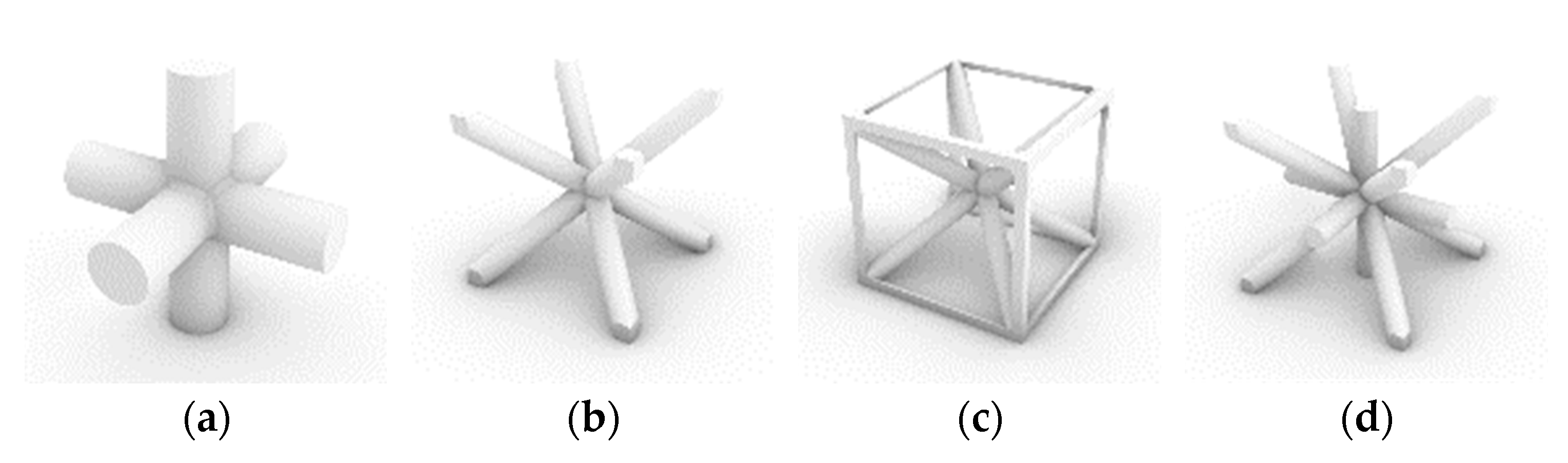
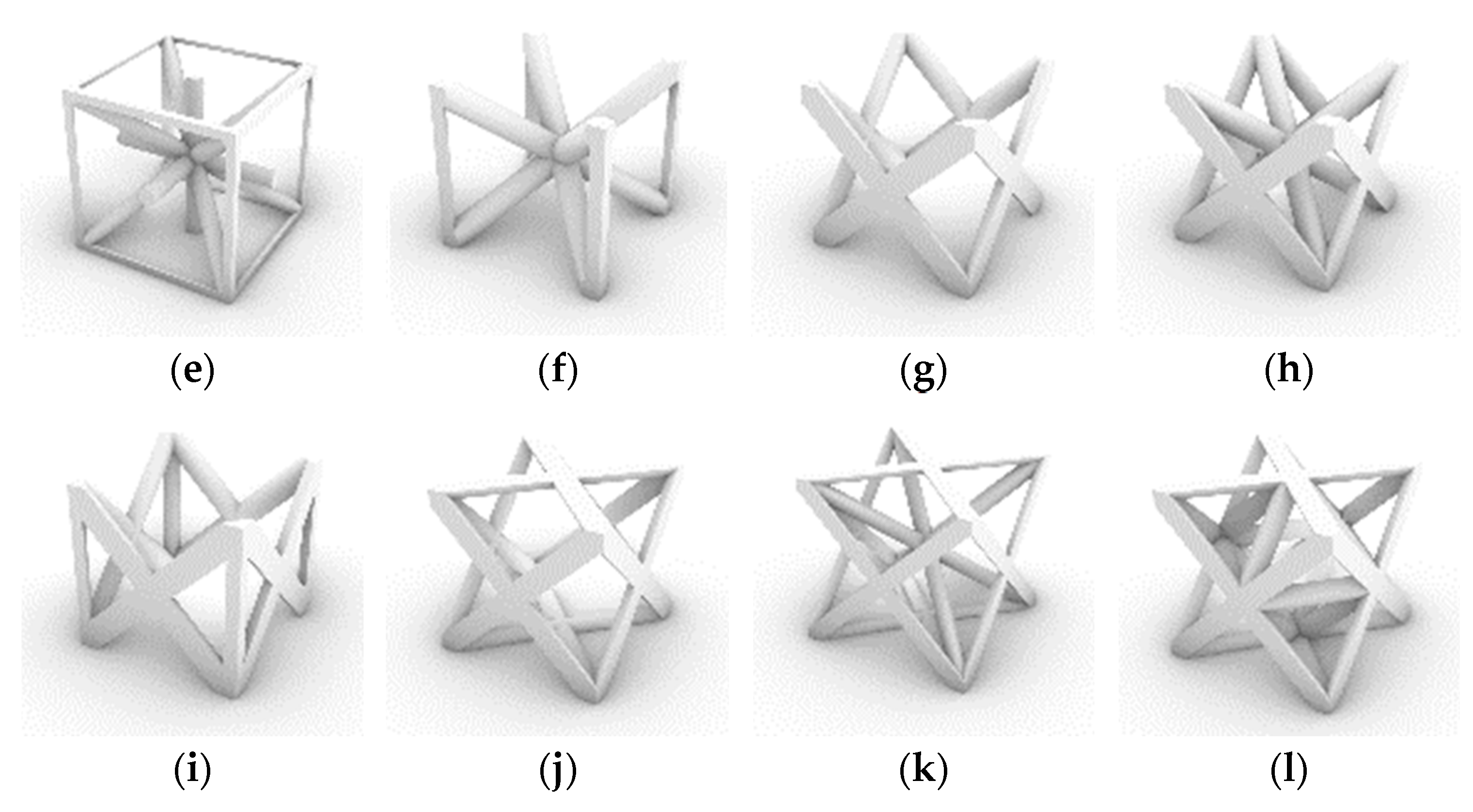
Figure 1.
Different types of strut-based base cells most commonly used in lattice structure design, (
a) centered cubic (CC), (
b) body-centered cubic (BCC), (
c) simple cubic body-centered cubic (SCBCC), (
d) centered body-centered cubic (CBCC), (
e) Iso truss, (
f) body-centered cubic with Z-struts (BCCZ), (
g) simple face-centered cubic (S-FCC), (
h) simple face- and body-centered cubic (S-FBCC), (
i) simple face-centered cubic with Z-struts (S-FCCZ), (
j) face-centered cubic (FCC), (
k) face- and body-centered cubic (FBCC), (
l) octet truss based on [
32,
34,
35,
36].
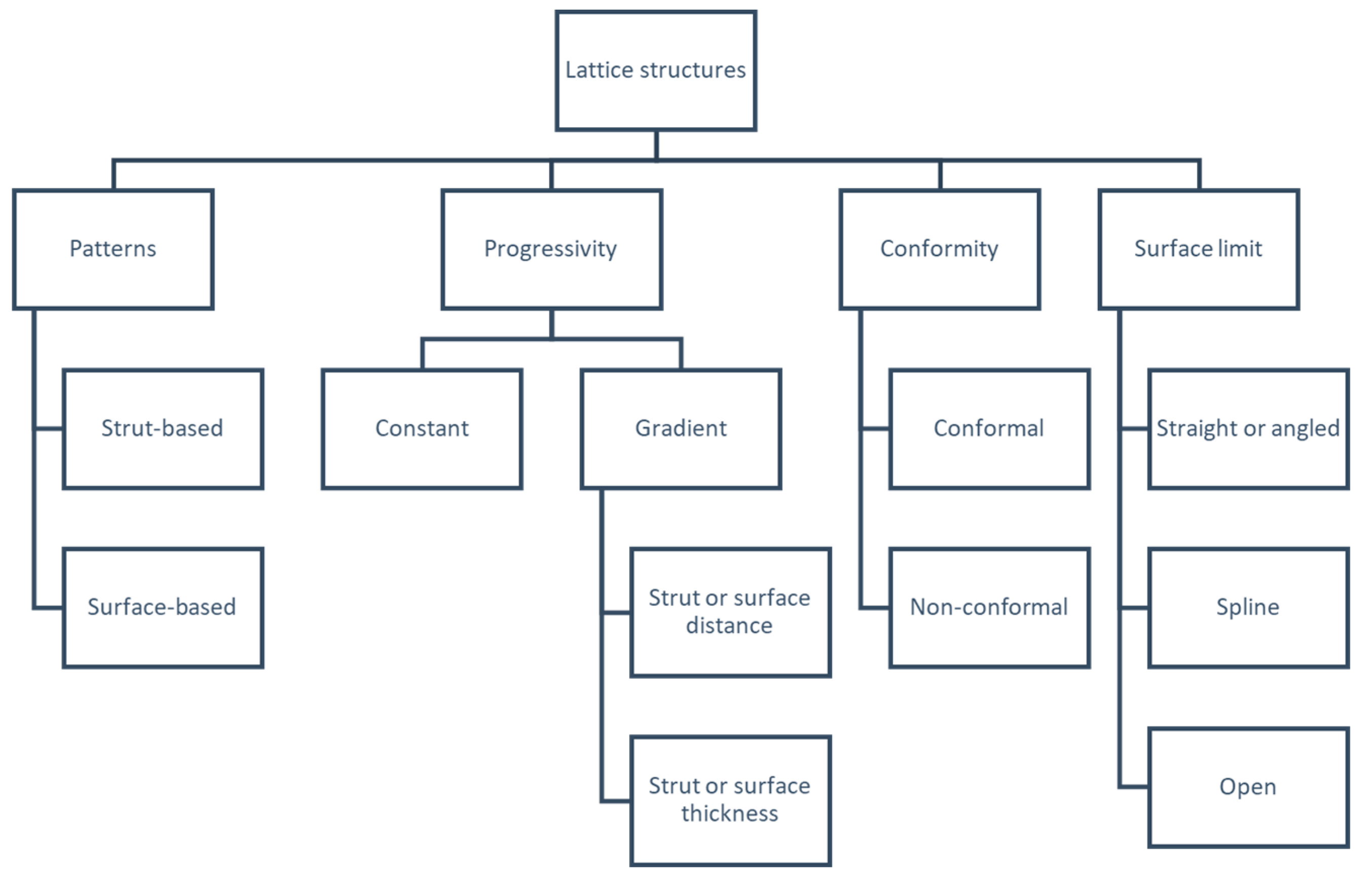
Figure 2.
Lattice structure design variables, based on [
24].
Figure 2.
Lattice structure design variables, based on [
24].
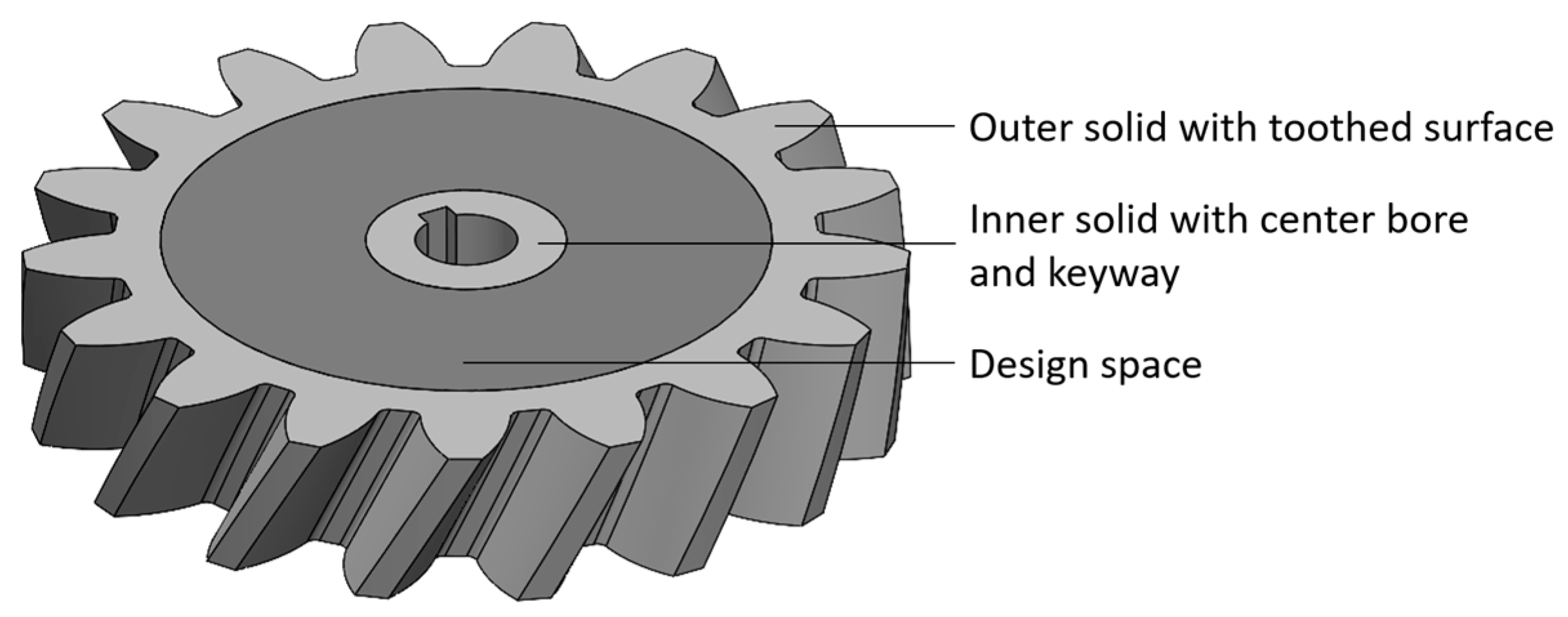
Figure 3.
Proposed model of a helical gear consisting of three individual geometries.
Figure 3.
Proposed model of a helical gear consisting of three individual geometries.
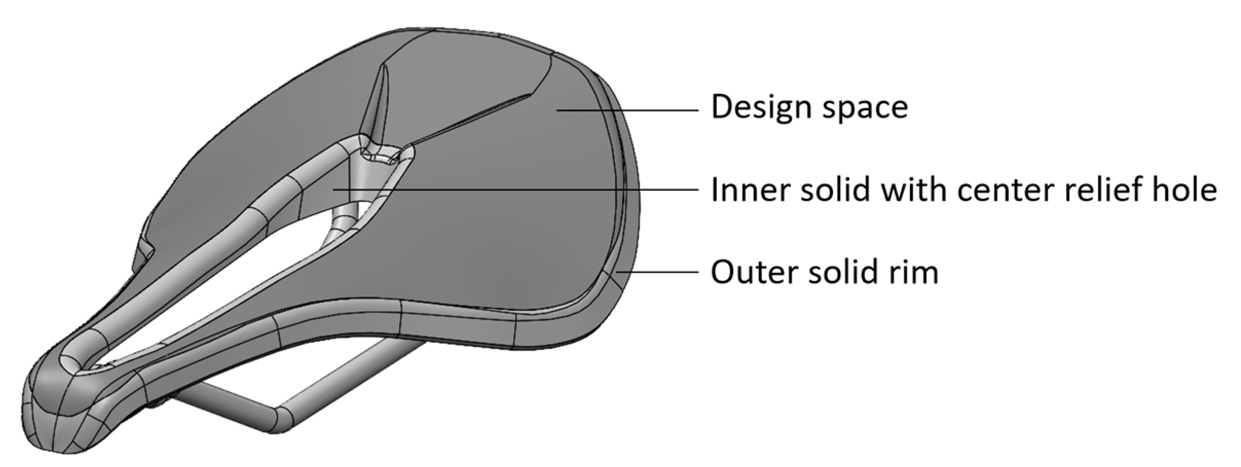
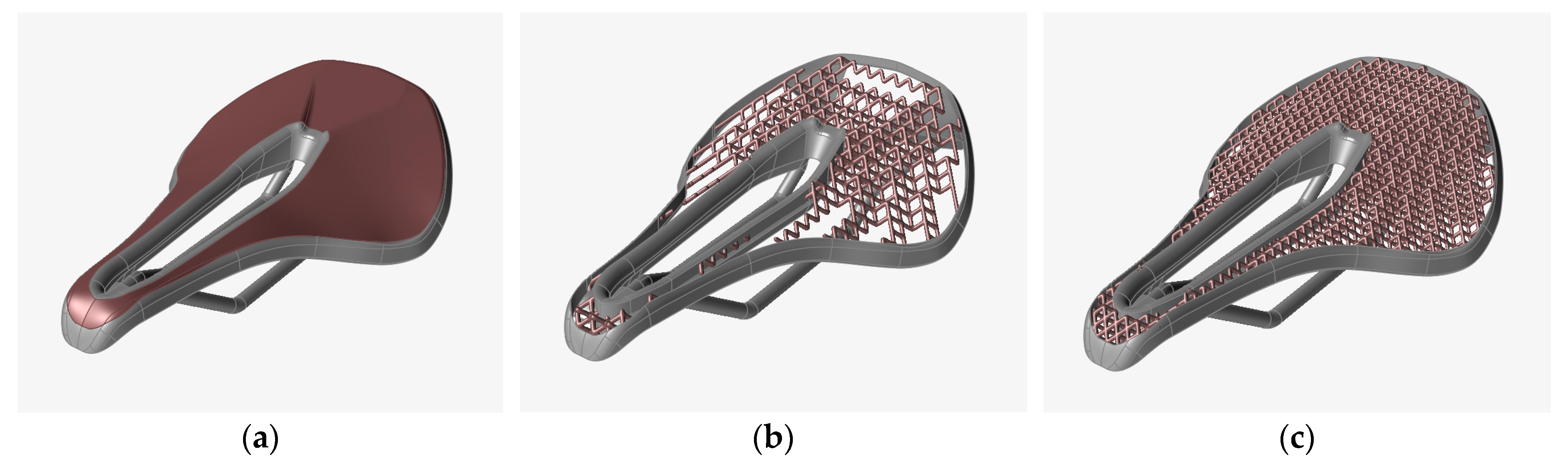
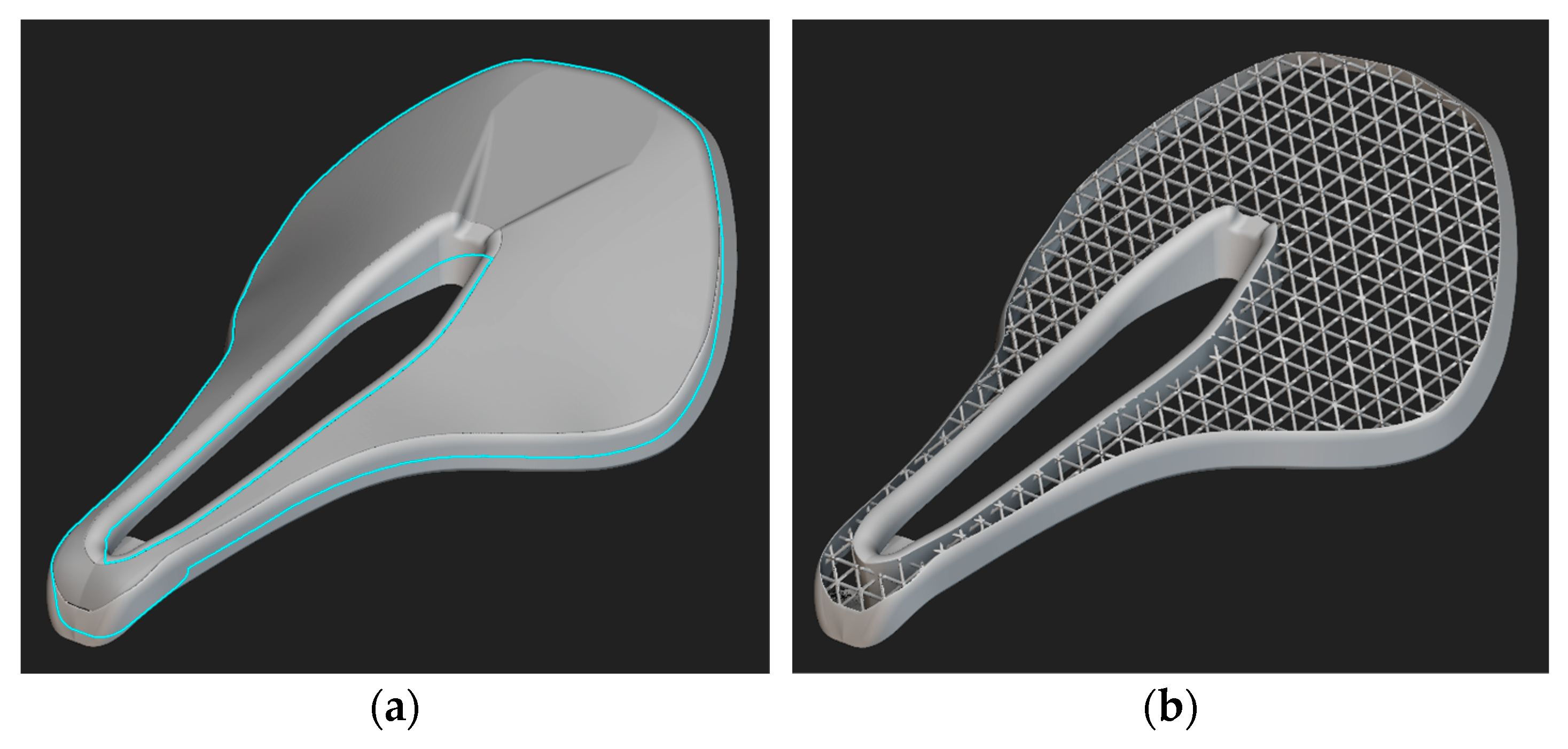
Figure 4.
Modified CAD model of the bike seat, based on [
51].
Figure 4.
Modified CAD model of the bike seat, based on [
51].
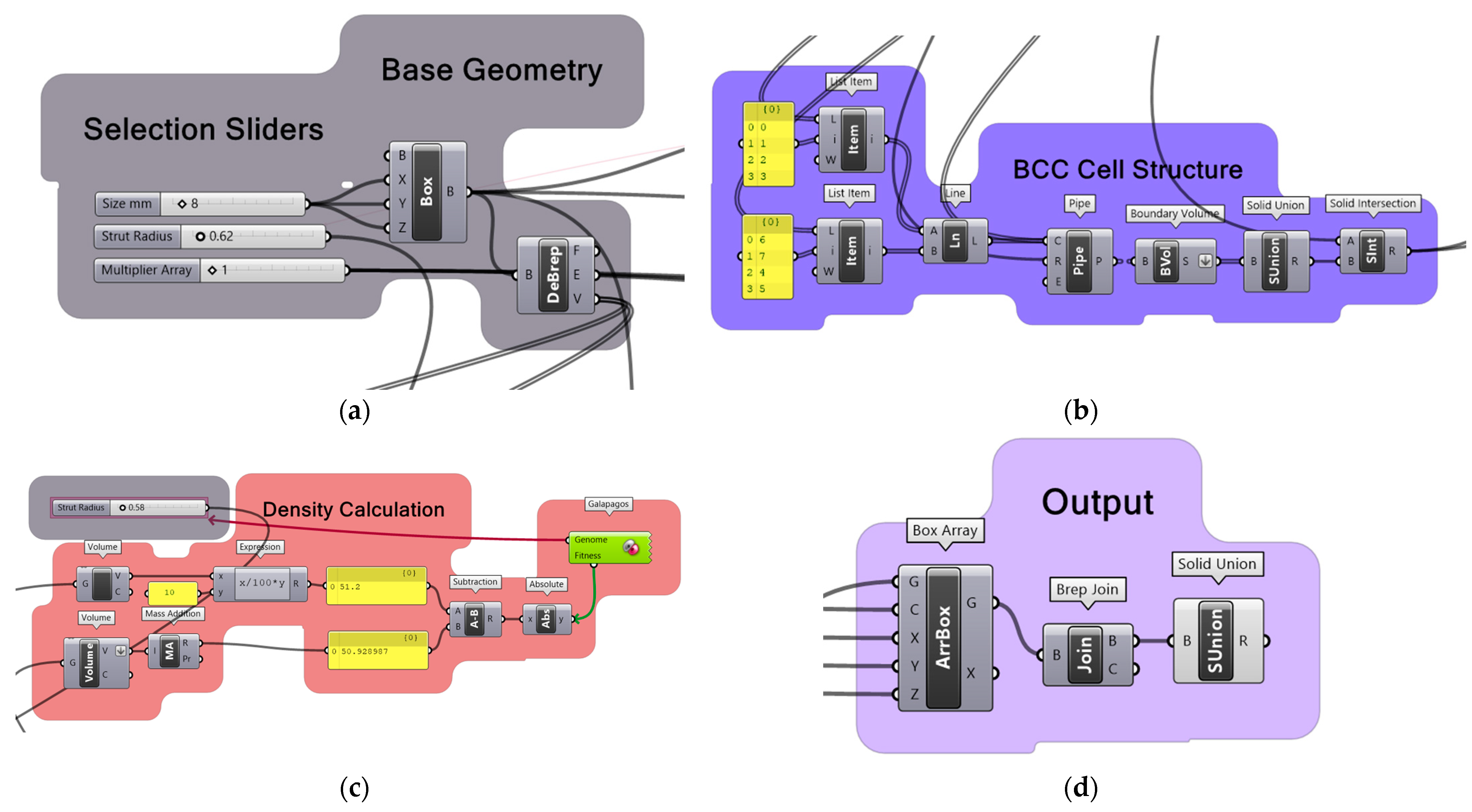
Figure 5.
Grasshopper® algorithms, (a) cubic base geometry, (b) BCC Base Cell formulation by connecting defined vertices and adding round cross sections as well as volumes, (c) Genome-based density calculation to 25% density of base cell geometry with strut radius as controlled value, and (d) output of the lattice structure array with Boolean operation solid union.
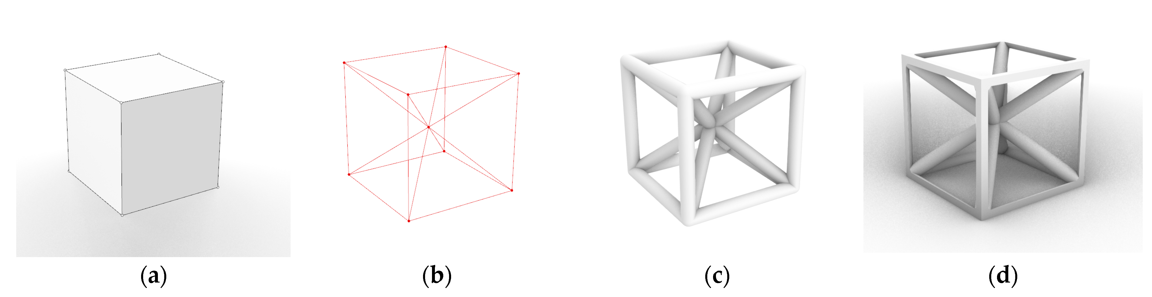
Figure 6.
Generation of a SCBCC base cell in Grasshopper®, (a) domain box, (b) vertices and lines, (c) pipe volume, and (d) SCBCC base cell after solid intersection with domain box.
Figure 6.
Generation of a SCBCC base cell in Grasshopper®, (a) domain box, (b) vertices and lines, (c) pipe volume, and (d) SCBCC base cell after solid intersection with domain box.
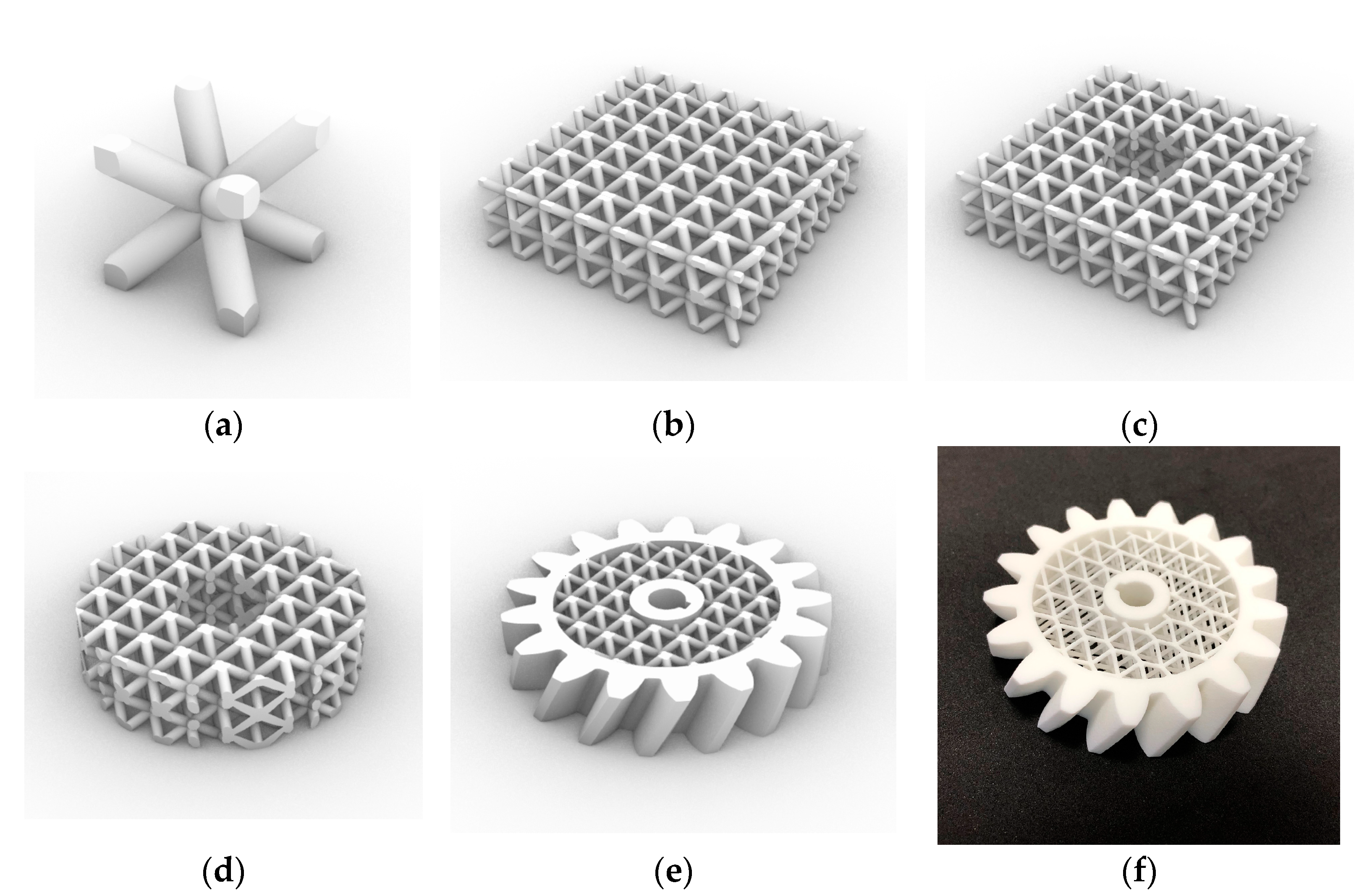
Figure 7.
BCC simple lattice structure generation for parts of a gear’s solid domain: (a) 8 × 8 × 8 mm BCC base cell, (b) 7 × 7 × 2 lattice structure, (c) lattice structure after inner cutout, (d) lattice structure after solid intersection with BRep_design_space, (e) finished gear after solid intersection of BRep_Gear with lattice structure BRep_design_space, and (f) manufactured gear using LPBF.
Figure 8.
Different types of tessellations of the bike seat’s design space: (a) non-conformal BCC lattice structure (left) and conformal tessellation with quadratic lattice structure (right) and (b) mesh representation of the upper bike saddle surface (left) and quadratic mesh (right).
Figure 8.
Different types of tessellations of the bike seat’s design space: (a) non-conformal BCC lattice structure (left) and conformal tessellation with quadratic lattice structure (right) and (b) mesh representation of the upper bike saddle surface (left) and quadratic mesh (right).
Figure 9.
Workflow for the helical gear in nTop: (a) design space and solid volumes and (b) generated lattice structure.
Figure 9.
Workflow for the helical gear in nTop: (a) design space and solid volumes and (b) generated lattice structure.
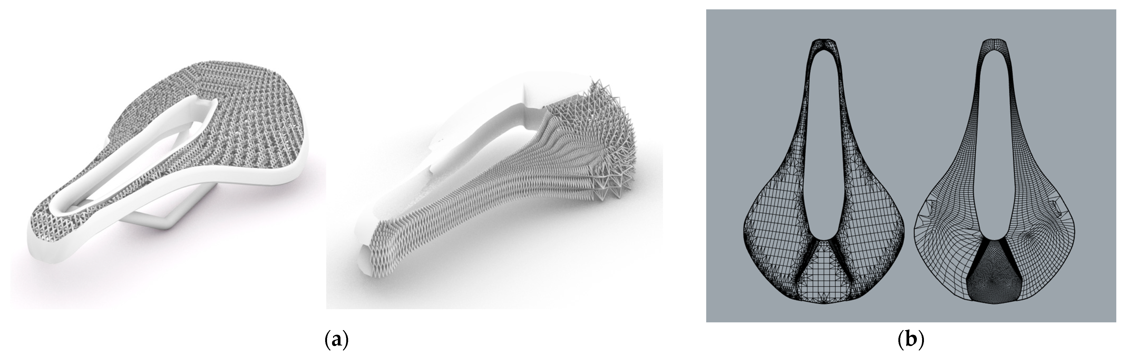
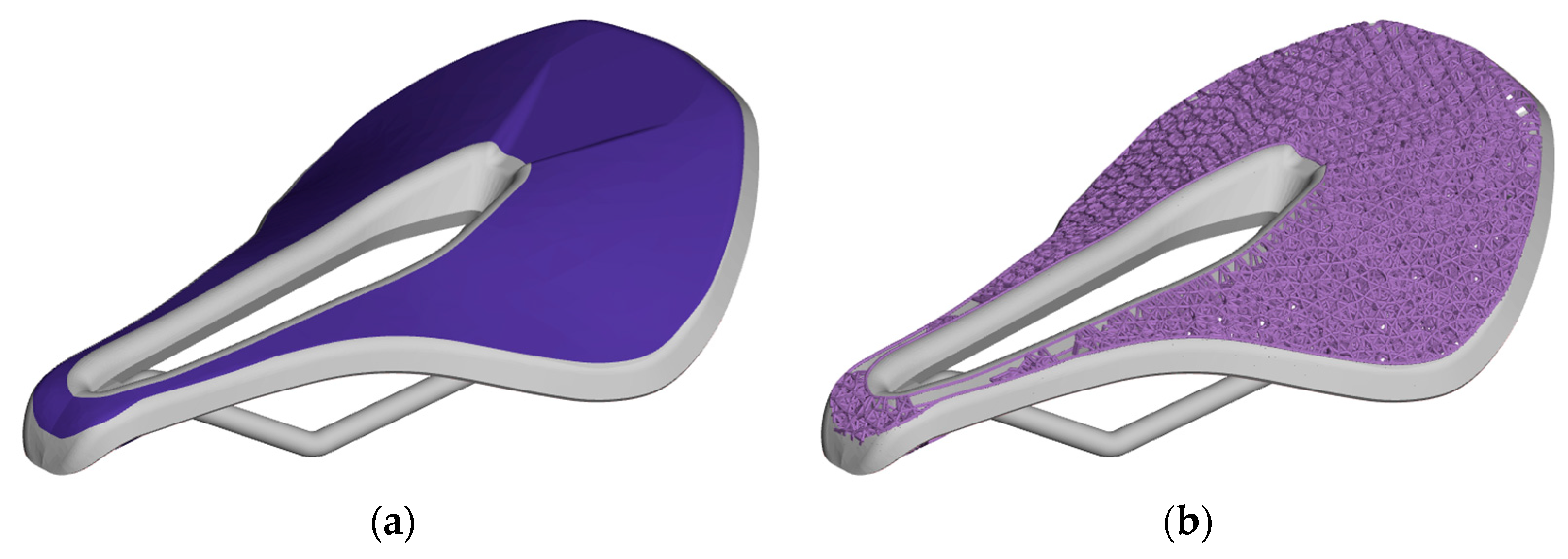
Figure 10.
Workflow for the bike seat in nTop: (a) design space and solid volumes and (b) generated lattice structure.
Figure 10.
Workflow for the bike seat in nTop: (a) design space and solid volumes and (b) generated lattice structure.
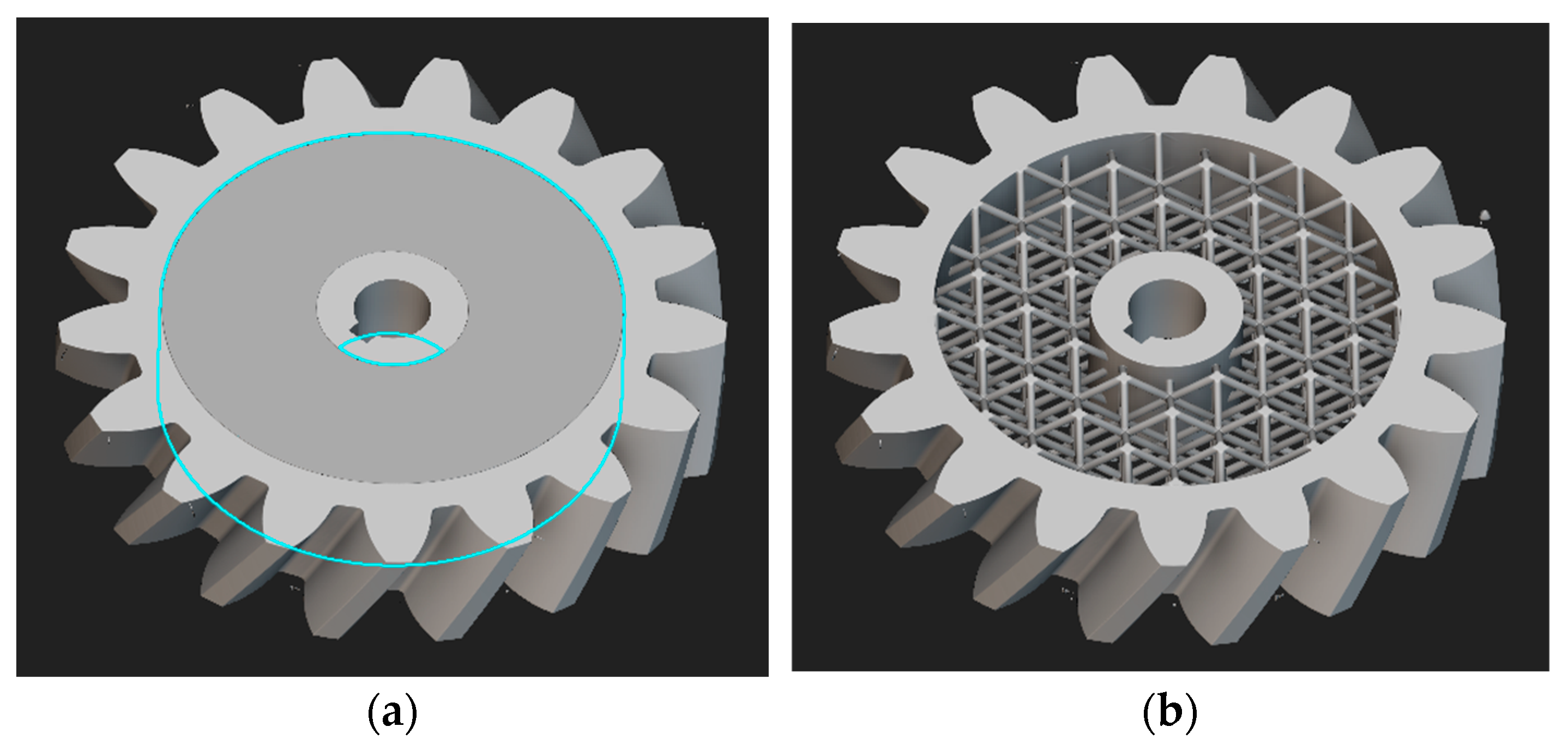
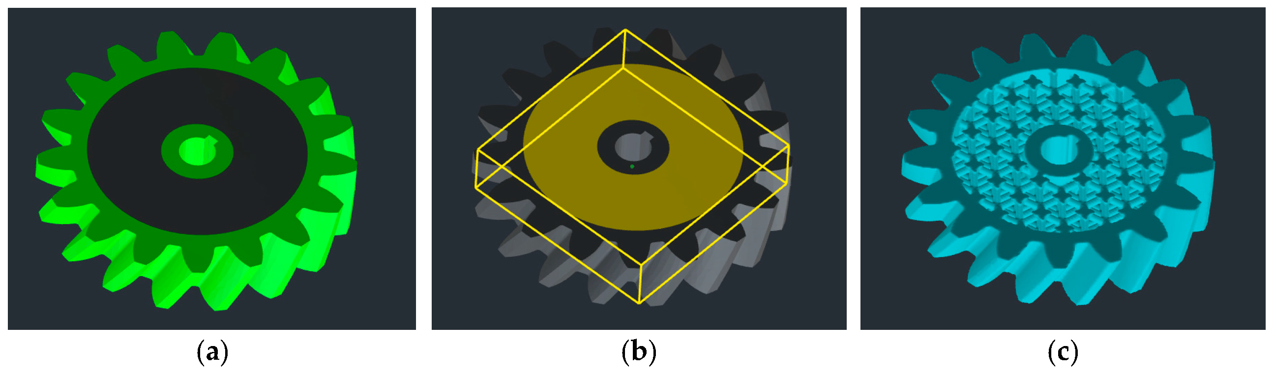
Figure 11.
Workflow for the helical gear in Sulis™: (a) solid areas of the model, (b) design space, and (c) generated lattice structure.
Figure 11.
Workflow for the helical gear in Sulis™: (a) solid areas of the model, (b) design space, and (c) generated lattice structure.
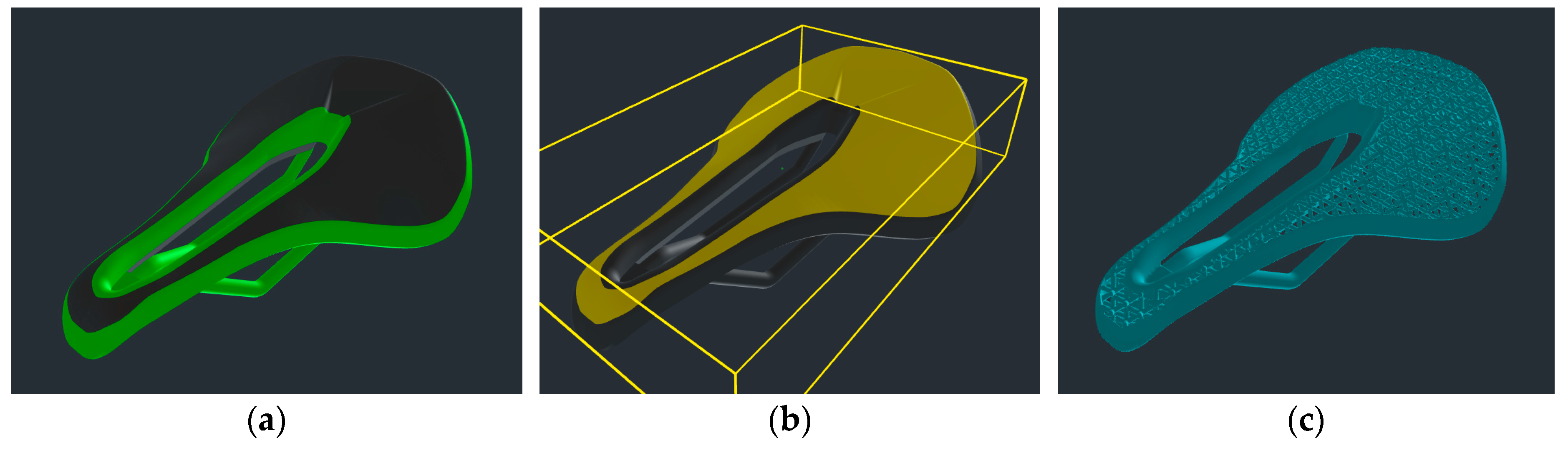
Figure 12.
Workflow for the bike seat in SulisTM: (a) solid areas of the model, (b) design space, and (c) generated lattice structure.
Figure 12.
Workflow for the bike seat in SulisTM: (a) solid areas of the model, (b) design space, and (c) generated lattice structure.
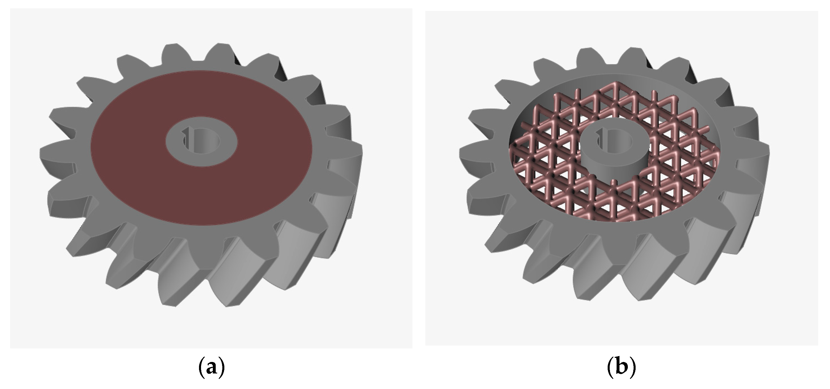
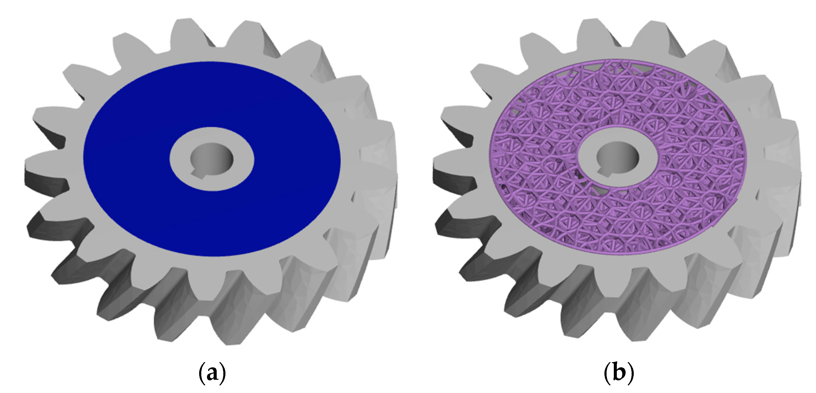
Figure 13.
Workflow for the helical gear in Inspire: (a) design space and (b) generated lattice structure.
Figure 13.
Workflow for the helical gear in Inspire: (a) design space and (b) generated lattice structure.
Figure 14.
Workflow for the bike seat in Inspire: (a) design space, (b), failed population of design space, and (c) generated lattice structure.
Figure 14.
Workflow for the bike seat in Inspire: (a) design space, (b), failed population of design space, and (c) generated lattice structure.
Figure 15.
Workflow for the helical gear in Design Studio Pro: (a) design space and (b) generated lattice structure.
Figure 15.
Workflow for the helical gear in Design Studio Pro: (a) design space and (b) generated lattice structure.
Figure 16.
Workflow for the bike seat in Design Studio Pro: (a) design space and (b) generated lattice structure.
Figure 16.
Workflow for the bike seat in Design Studio Pro: (a) design space and (b) generated lattice structure.
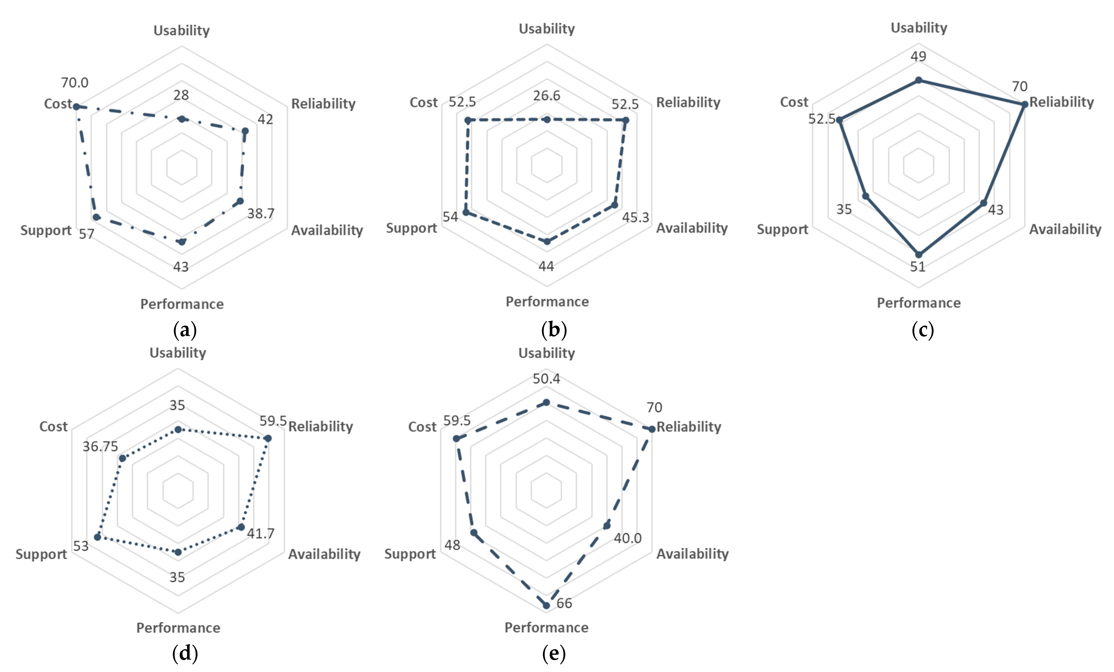
Figure 17.
Evaluation of the benchmarked attributes. Rhino7/Grasshopper® (a), nTopology nTop (b), Altair® SulisTM (c), Altair® InspireTM (d), and Carbon Design Engine Pro (e).
Figure 17.
Evaluation of the benchmarked attributes. Rhino7/Grasshopper® (a), nTopology nTop (b), Altair® SulisTM (c), Altair® InspireTM (d), and Carbon Design Engine Pro (e).
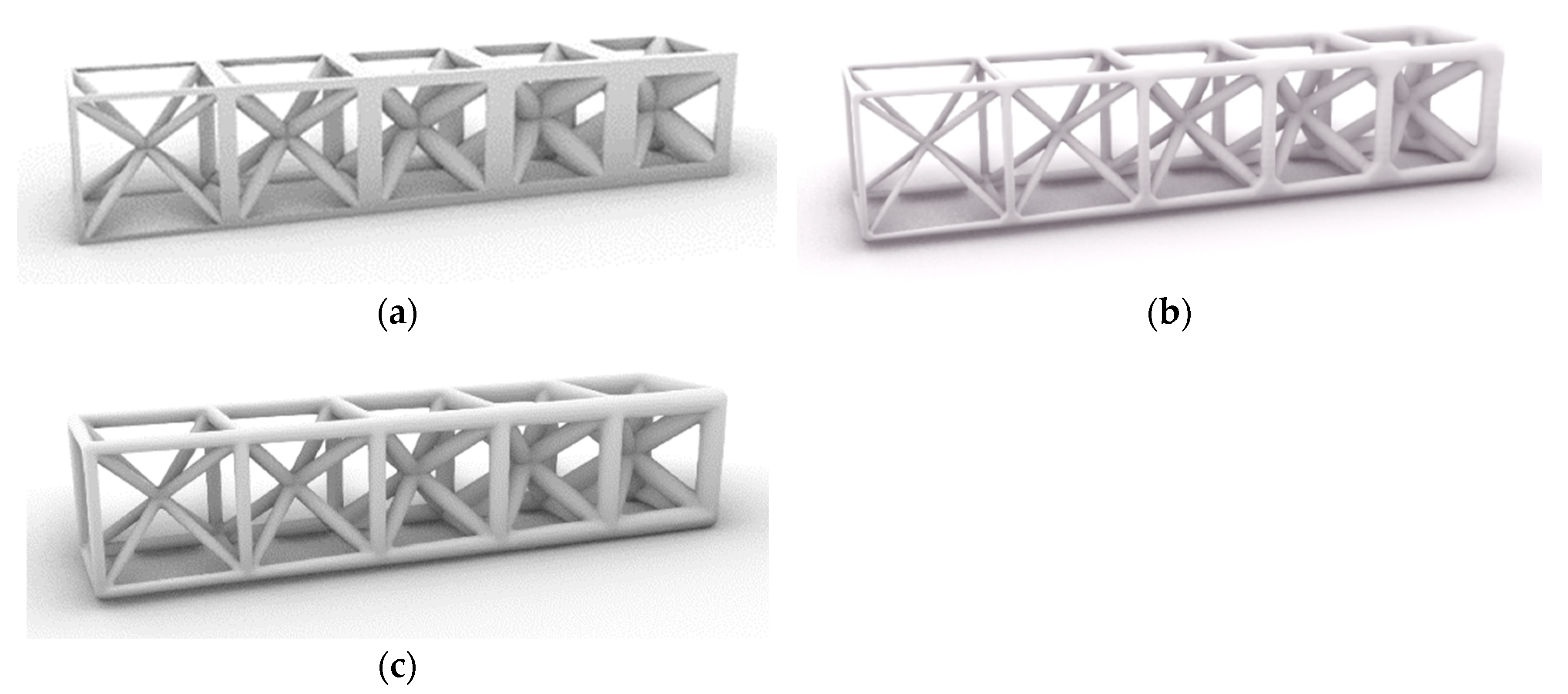
Figure 18.
Example 1 × 5 × 1 BCC lattice structures with gradient strut thickness: (a) Grasshopper basic functionality, (b) Grasshopper Intralattice plugin, and (c) Grasshopper Dendro plugin.
Figure 18.
Example 1 × 5 × 1 BCC lattice structures with gradient strut thickness: (a) Grasshopper basic functionality, (b) Grasshopper Intralattice plugin, and (c) Grasshopper Dendro plugin.
Table 1.
Shortlist of CAD software tools for lattice structure generation.
Table 1.
Shortlist of CAD software tools for lattice structure generation.
| Software | Lattice Toolbox | Repair Functionality | AM Process Integration | Visualization | Materials Database | Meshing Tools | Additional Tools Available | ∑ |
|---|
| Weight | 25% | 10% | 20% | 10% | 10% | 10% | 15% | 100% |
| Altair® InpireTM 2022.3 | 5 | 5 | 9 | 3 | 8 | 5 | 9 | 6.5 |
| Altair® Sulis™ 1.12 | 8 | 5 | 5 | 5 | 1 | 5 | 5 | 5.35 |
| Autodesk® Fusion 360 2.0.18220 | 5 | 3 | 3 | 5 | 8 | 6 | 5 | 4.8 |
| Carbon® Design Studio Pro | 8 | 8 | 10 | 8 | 5 | 8 | 5 | 7.65 |
| Materialise Magics 27 | 3 | 10 | 10 | 2 | 1 | 4 | 3 | 4.9 |
| nTopology nTop 4.19.2 | 10 | 10 | 10 | 7 | 8 | 10 | 10 | 9.5 |
| Rhino 7/Grasshopper® SR36 | 8 | 8 | 5 | 10 | 5 | 10 | 10 | 7.8 |
| SolidWorks 2023 SP 2.1 | 1 | 5 | 3 | 9 | 6 | 6 | 5 | 4.2 |
Table 2.
BCC and FCC lattice generation values of the helical gear in Rhino7/Grasshopper®.
Table 2.
BCC and FCC lattice generation values of the helical gear in Rhino7/Grasshopper®.
| Criteria | BCC | FCC | Relative Change |
|---|
| Lattice processing time | 33.6 s | 2 min 06 s | 275% |
| Resolution | 0.1 mm | 0.1 mm | |
| Export time | 1.2 s | 7.8 s | 550% |
| File size | 11.8 MB | 14.7 MB | 24.6% |
Table 3.
BCC and FCC lattice generation values of the bike seat in Rhino7/Grasshopper®.
Table 3.
BCC and FCC lattice generation values of the bike seat in Rhino7/Grasshopper®.
| Criteria | BCC | FCC | Relative Change |
|---|
| Lattice processing time | 21 min 48 s | 25 min 33 s | 17.2% |
| Resolution | 0.1 mm | 0.1 mm | |
| Export time | 17.59 s | 21.45 s | 21.9% |
| File size | 33.1 MB | 39.5 MB | 19.3% |
Table 4.
BCC and FCC lattice generation calculation times of the helical gear in nTop.
Table 4.
BCC and FCC lattice generation calculation times of the helical gear in nTop.
| Criteria | BCC | FCC | Relative Change |
|---|
| Outer solid | 20.83 s | 16.4 s | 27.0% |
| Design space | 14.04 s | 13.4 s | 4.8% |
| Inner solid | 13.99 s | 18.3 s | 30.8% |
| Full body | 46.05 s | 1 min 2 s | 34.6% |
| Implicit body | 1 min 6 s | 1 min 32 s | 39.4% |
| Total | 2 min 41 s | 3 min 22.1 s | 25.5% |
Table 5.
BCC and FCC lattice generation values of the helical gear in nTop.
Table 5.
BCC and FCC lattice generation values of the helical gear in nTop.
| Criteria | BCC | FCC | Relative Change |
|---|
| Lattice processing time | 2 min 40.9 s | 3 min 22.1 s | 25.6% |
| Resolution | 0.1 mm | 0.1 mm | |
| Export time | 4 min 14.95 s | 6 min 59 s | 64.3% |
| File size | 1382 MB | 1350 MB | 2.4% |
Table 6.
BCC and FCC lattice generation calculation times of the bike seat in nTop.
Table 6.
BCC and FCC lattice generation calculation times of the bike seat in nTop.
| Criteria | BCC | FCC | Relative Change |
|---|
| Outer solid | 1 min 27.3 s | 1 min 42 s | 16.8% |
| Full body | 3 min 29.1 s | 3 min 40 s | 5.2% |
| Implicit body | 3 min 44.8 s | 3 min 35 s | 4.6% |
| Total | 8 min 41.2 s | 8 min 57 s | 3.0% |
Table 7.
BCC and FCC lattice generation values of the bike seat in nTop.
Table 7.
BCC and FCC lattice generation values of the bike seat in nTop.
| Criteria | BCC | FCC | Relative Change |
|---|
| Lattice processing time | 8 min 41.15 s | 8 min 59.1 s | 3.4% |
| Resolution | 0.1 mm | 0.1 mm | |
| Export time | failed | failed | |
| File size | failed | failed | |
Table 8.
BCC and FCC lattice generation values of the helical gear in Altair® Sulis™.
Table 8.
BCC and FCC lattice generation values of the helical gear in Altair® Sulis™.
| Criteria | BCC | FCC | Relative Change |
|---|
| Lattice processing time | 1 min 37 s | 1 min 45 s | 8.2% |
| Resolution | 0.1 mm | 0.1 mm | |
| Export time | 1 min 11 s | 51 s | 19.6% |
| File size | 413 MB | 436 MB | 5.6% |
Table 9.
BCC and FCC lattice generation values of the bike seat in Altair® Sulis™.
Table 9.
BCC and FCC lattice generation values of the bike seat in Altair® Sulis™.
| Criteria | BCC | FCC | Relative Change |
|---|
| Lattice processing time | 1 min 6 s | 1 min 22 s | 24.2% |
| Resolution | 0.5 mm | 0.5 mm | |
| Export time | 7.5 s | 8.2 s | 9.3% |
| File size | 56.1 MB | 60 MB | 7% |
Table 10.
BCC and FCC lattice generation values of the helical gear in Altair® Inspire™.
Table 10.
BCC and FCC lattice generation values of the helical gear in Altair® Inspire™.
| Criteria | BCC | FCC | Relative Change |
|---|
| Lattice processing time | 1.2 s | 1.2 | 0% |
| Boolean unify time | 5.5 s | 16.1 s | 192.7% |
| Resolution | no information | no information | |
| Export time | 3.6 s | 4.7 s | 30.6% |
| File size | 28.5 MB | 120 MB | 321.1% |
Table 11.
BCC and FCC lattice generation values of the bike seat in Altair® Inspire™.
Table 11.
BCC and FCC lattice generation values of the bike seat in Altair® Inspire™.
| Criteria | BCC | FCC | Relative Change |
|---|
| Unit cell dimensions | 5.5 × 5.5 × 5.5 mm | 5.5 × 5.5 × 5.5 mm | |
| Strut thickness | 1 mm | 1 mm | |
| Lattice dimension | no information | no information | |
| Lattice processing time | 19.8 s | 53 s | 167.7% |
| Boolean unify time | 1 min 18 s | 3 min 31 s | 170.5% |
| Resolution | no information | no information | |
| Export time | 21.1 s | 51 s | 141.7% |
| File size | 464 MB | 1140 MB | 145.7% |
Table 12.
Tetrahedral and icosahedral lattice generation calculation times of the helical gear in Design Engine Pro.
Table 12.
Tetrahedral and icosahedral lattice generation calculation times of the helical gear in Design Engine Pro.
| Criteria | Icosahedral | Tetrahedral | Relative Change |
|---|
| Lattice processing time | 17.4 s | 20.9 s | 20.1% |
| Lattice solidifying time | 19.8 s | 21.35 s | 7.8% |
| Lattice combine time | 21.4 s | 25 s | 16.8% |
| Total | 58.6 s | 1 min 7.2 s | 14.7% |
Table 13.
Tetrahedral and icosahedral lattice generation values of the helical gear in Design Engine Pro.
Table 13.
Tetrahedral and icosahedral lattice generation values of the helical gear in Design Engine Pro.
| Criteria | Tetrahedral | Icosahedral | Relative Change |
|---|
| Resolution | no information | no information | |
| Export time | 10.7 s | 12.6 s | 17.8% |
| File size | 8.2 MB | 15.7 MB | 91.5% |
Table 14.
Tetrahedral and icosahedral lattice generation calculation times of the bike seat in Design Engine Pro.
Table 14.
Tetrahedral and icosahedral lattice generation calculation times of the bike seat in Design Engine Pro.
| Criteria | Tetrahedral | Icosahedral | Relative Change |
|---|
| Lattice processing time | 36.9 s | 33.78 s | 9.2% |
| Lattice solidifying time | 1 min 19.6 s | 21.04 s | 278.3% |
| Lattice combine time | 23.7 s | 34.13 s | 44.0% |
| Total | 2 min 33 s | 1 min 28.95 s | 72.0% |
Table 15.
Tetrahedral and icosahedral lattice generation values of the bike seat in Design Engine Pro.
Table 15.
Tetrahedral and icosahedral lattice generation values of the bike seat in Design Engine Pro.
| Criteria | Tetrahedral | Icosahedral | Relative Change |
|---|
| Resolution | no information | no information | |
| Export time | 12.8 s | 28.63 s | 123.7% |
| File size | 21.4 MB | 50.6 MB | 136.4% |
Table 16.
Evaluation of the selected features for the usability benchmarking.
Table 16.
Evaluation of the selected features for the usability benchmarking.
| Feature | Rhino7/Grasshopper® | nTopology nTop | Altair® Sulis | Altair® InspireTM | Carbon® Design Engine Pro |
|---|
| Ease of use/intuitive use | 2 | 3 | 7 | 5 | 9 |
| Special training required | 1 | 2 | 7 | 6 | 8 |
| Previous experience required | 3 | 5 | 6 | 6 | 5 |
| Intuitive workflow | 6 | 4 | 7 | 4 | 7 |
| Learning curve | 8 | 5 | 8 | 4 | 7 |
| ∑ | 20 | 19 | 35 | 25 | 36 |
| Total possible | 50 | 50 | 50 | 50 | 50 |
Table 17.
Evaluation of the selected features for the reliability benchmarking.
Table 17.
Evaluation of the selected features for the reliability benchmarking.
| Feature | Rhino7/Grasshopper® | nTopology nTop | Altair® Sulis | Altair® InspireTM | Carbon® Design
Engine Pro |
|---|
| Stability of program | 6 | 10 | 10 | 7 | 10 |
| Handling of large, complex structures | 6 | 5 | 10 | 10 | 10 |
| ∑ | 12 | 15 | 20 | 17 | 20 |
| Total possible | 20 | 20 | 20 | 20 | 20 |
Table 18.
Evaluation of the selected features for the availability benchmarking.
Table 18.
Evaluation of the selected features for the availability benchmarking.
| Feature | Rhino7/Grasshopper® | nTopology nTop | Altair® Sulis | Altair® InspireTM | Carbon® Design Engine Pro |
|---|
| Student version | 2 | 10 | 10 | 10 | 3 |
| Faculty version | 2 | 10 | 10 | 10 | 3 |
| Trial version | 6 | 2 | 2 | 1 | 5 |
| Affordable classroom version | 10 | 5 | 3 | 3 | 1 |
| Updates | 7 | 10 | 3 | 6 | 8 |
| OS * compatibility | 6.66 | 3.33 | 10 | 6.66 | 10 |
| Web-based or desktop-based versions | 5 | 5 | 5 | 5 | 10 |
| ∑ | 38.66 | 45.33 | 43 | 41.66 | 40 |
| Total possible | 70 | 70 | 70 | 70 | 70 |
Table 19.
Evaluation of the selected features for the performance benchmarking.
Table 19.
Evaluation of the selected features for the performance benchmarking.
| Feature | Rhino7/Grasshopper® | nTopology nTop | Altair® Sulis | Altair® InspireTM | Carbon® Design Engine Pro |
|---|
| Hardware requirements user | 8 | 4 | 7 | 5 | 10 |
| Calculation times | 5 | 3 | 9 | 10 | 7 |
| Cloud computing support | 5 | 1 | 1 | 1 | 10 |
| Yields expected results | 6 | 8 | 8 | 5 | 10 |
| Yields closed lattice structures | 5 | 8 | 8 | 3 | 9 |
| Can generate strut-based lattice structures | 7 | 10 | 10 | 10 | 10 |
| Can generate other types of structures | 7 | 10 | 8 | 1 | 10 |
| ∑ | 43 | 44 | 51 | 35 | 66 |
| Total possible | 70 | 70 | 70 | 70 | 70 |
Table 20.
Evaluation of the selected features for the support benchmarking.
Table 20.
Evaluation of the selected features for the support benchmarking.
| Feature | Rhino7/Grasshopper® | nTopology nTop | Altair® Sulis | Altair® InspireTM | Carbon® Design Engine Pro |
|---|
| Online training | 10 | 8 | 1 | 10 | 10 |
| Webinars | 8 | 9 | 1 | 8 | 10 |
| Knowledge base | 10 | 7 | 10 | 8 | 1 |
| Tutorials | 8 | 8 | 1 | 7 | 4 |
| Video documentation | 10 | 8 | 7 | 9 | 8 |
| Comprehensive user manuals | 4 | 6 | 8 | 5 | 6 |
| Costumer support | 7 | 8 | 7 | 6 | 9 |
| ∑ | 57 | 54 | 35 | 53 | 48 |
| Total possible | 70 | 70 | 70 | 70 | 70 |
Table 21.
Evaluation of the selected features for the cost benchmarking.
Table 21.
Evaluation of the selected features for the cost benchmarking.
| Feature | Rhino7/Grasshopper® | nTopology nTop | Altair® Sulis | Altair® InspireTM | Carbon® Design Engine Pro |
|---|
| Initial cost | 10 | 5 | 5 | 3 | 7 |
| Operating cost | 10 | 5 | 5 | 3 | 7 |
| Subscriptions | 10 | 10 | 10 | 10 | 10 |
| Additional tools | 10 | 10 | 10 | 5 | 10 |
| ∑ | 40 | 30 | 30 | 21 | 34 |
| Total possible | 40 | 40 | 40 | 40 | 40 |
Table 22.
Evaluation of the selected attributes for the overall benchmarking of the investigated software tools.
Table 22.
Evaluation of the selected attributes for the overall benchmarking of the investigated software tools.
| Attribute | Factor | Rhino7/Grasshopper® | nTopology nTop | Altair® Sulis | Altair® InspireTM | Carbon® Design
Engine Pro |
|---|
| Usability | 1.4 | 20 | 19 | 35 | 25 | 36 |
| Reliability | 3.5 | 12 | 15 | 20 | 17 | 20 |
| Availability | 1 | 38.66 | 45.33 | 43 | 41.66 | 40 |
| Performance | 1 | 43 | 44 | 51 | 35 | 66 |
| Support | 1 | 57 | 54 | 35 | 53 | 48 |
| Cost | 1.75 | 40 | 30 | 30 | 21 | 34 |
| ∑ | | 210.66 | 207.33 | 214 | 192.66 | 244 |
| Total possible | 420 | 320 | 320 | 320 | 320 | 320 |


