Approach to Modernizing Residential-Dominated District Heating Systems to Enhance Their Flexibility, Energy Efficiency, and Environmental Friendliness


Abstract
:1. Introduction
2. State of the Art
- Stimulating the reduction in thermal pollution during thermal energy transmission and consumption;
- Boosting the DHS controllability to reduce harmful emissions into the environment from the thermal energy production.
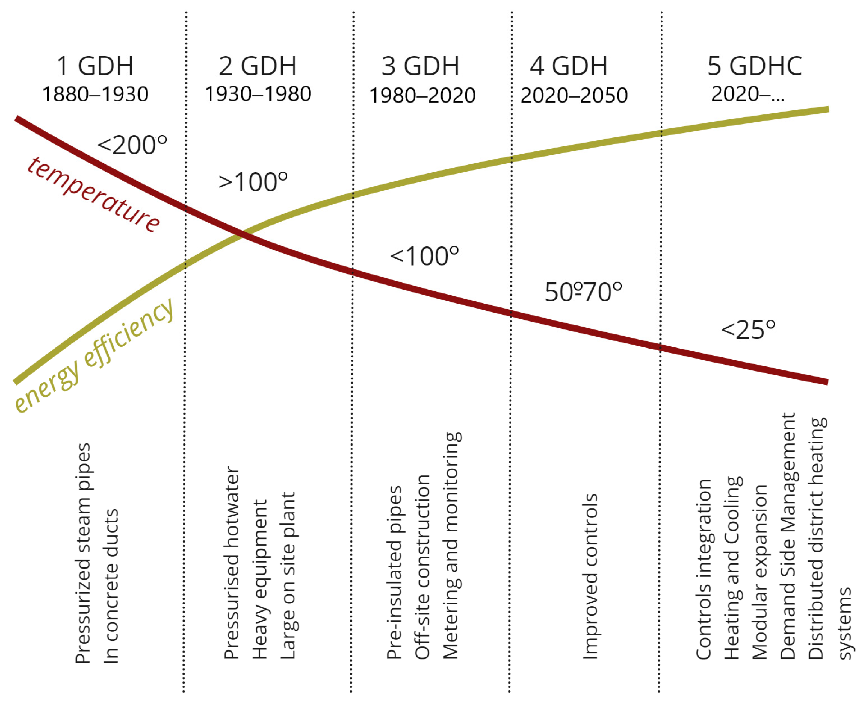
- The first generation (1 GDH) is characterized by steam heating with a steam temperature of 100–200 °C and high thermal energy losses exceeding 30%. It is mainly used in steam boilers operating on solid fuels (coal, peat, etc.).
- The second generation (2 GDH) is characterized by water heating with a network water temperature above 100 °C at high pressure and high thermal energy losses (up to 30%). These DHSs mainly focus on providing heat to industrial consumers, while the surplus thermal energy is used to meet the needs of household consumers. They can include heat and electricity cogeneration plants operating mainly on solid fuels.
- The third generation (3 GDH) is characterized by water heating with a network water temperature of 70–100 °C for heat supply to domestic consumers. Energy saving measures are implemented to reduce thermal energy losses during the coolant transfer from the source to consumers (up to 18%) and to control harmful emissions from the combustion of hydrocarbon fuels. Thermal energy sources use solid and gaseous fuels [44]. Cogeneration technologies are widely used to generate heat and electricity. There is an insignificant share of generation (up to 10%) using renewable energy resources [45].
- The fourth generation (4 GDH) is characterized by a network water temperature of 50–70 °C, while heat losses do not exceed 6%. Secondary and renewable energy resources are massively used; heat storage, automation, and digitalization systems are introduced into the processes of thermal energy production and distribution [46,47]. Along with efficient cogeneration technologies, heat pumps, solar collectors, and other plants based on renewable energy resources are used to produce thermal energy. Trigeneration technologies are utilized for the air conditioning of buildings, enhancing the capabilities of district heating systems.
- The fifth generation (5 GDHC) is characterized by a coolant temperature from 5 to 25 °C, while heat losses do not exceed 5%. Highly efficient thermal energy sources are utilized that make use of secondary energy resources such as solid industrial, agricultural, and domestic waste to minimize CO2 emissions. These district heating systems employ integrated automation systems as the basis for intelligent control systems to be created [48].
- Hydrocarbon fuels, industrial, agricultural, and domestic solid waste (boilers, combined heat and power plants (CHPPs));
- Renewable energy resources (heat pumps, solar collectors, etc.);
- Electricity (electric boiler rooms, individual electric boilers) [50].
3. Materials and Methods
4. Results and Discussion
4.1. Modeling Example
4.2. Enhancing the Energy Efficiency of Thermal Energy Production
4.3. Boosting the DHS Technical Reliability
4.4. Increasing the DHS Cost-Effectiveness
4.5. Establishment of Intelligent Control Systems for DHSs
5. Conclusions
Future Research Directions
Author Contributions
Funding
Institutional Review Board Statement
Informed Consent Statement
Data Availability Statement
Conflicts of Interest
References
- Glazkova, V.V. Principles of Ecological and Economic Management of Innovative Development of Heat Supply. In Finance, Economics, and Industry for Sustainable Development; Springer: Cham, Switzerland, 2023. [Google Scholar] [CrossRef]
- Bergen, D. Alternative Options for Modernization of Regional Heat Supply Systems: Environmental and Economic Aspects. Bull. Baikal State Univ. 2021, 31, 407–415. [Google Scholar] [CrossRef]
- Zheliuk, T. Management of modernization of heat supply system of the region in the context of its sustainable development. Her. Ternopil Natl. Econ. Univ. 2020, 3, 20–36. [Google Scholar] [CrossRef]
- Chebotarova, Y.; Perekrest, A. Modernization of electrical complex for producing thermal energy for an industrial enterprise. Technol. Audit Prod. Reserves 2022, 5, 25–32. [Google Scholar] [CrossRef]
- Biev, A.A. Formation of Territorial Heat Supply Systems in the Northern and Arctic Regions of Russia. Arct. North 2023, 51, 28–51. [Google Scholar] [CrossRef]
- Gorinov, Y.A.; Anisimov, P.N. Icreasing the efficiency of district heating supply systems by local heat distribution station modernation. Power Eng. Res. Equip. Technol. 2022, 24, 101–111. [Google Scholar] [CrossRef]
- Chen, W.; Huang, Z.; Chua, K.J. Sustainable energy recovery from thermal processes: A review. Energy Sustain. Soc. 2022, 12, 46. [Google Scholar] [CrossRef]
- An, Y.; Fu, Y.; Dai, J.G.; Yin, X.; Lei, D. Switchable radiative cooling technologies for smart thermal management. Cell Rep. Phys. Sci. 2022, 3, 101098. [Google Scholar] [CrossRef]
- Nasir, M.T.; Kim, M.; Lee, J.; Kim, S.; Kim, K.C. A review on technologies with electricity generation potentials using liquified natural gas regasification cold energy. Front. Energy 2023, 17, 332–379. [Google Scholar] [CrossRef]
- Bai, H.Y.; Liu, P.; Alonso, M.J.; Mathisen, H.M. A review of heat recovery technologies and their frost control for residential building ventilation in cold climate regions. Renew. Sustain. Energy Rev. 2022, 162, 112417. [Google Scholar] [CrossRef]
- Wang, W.; Huang, S.; Zhang, G.; Liu, J.; Chen, Z. Optimal Operation of an Integrated Electricity-heat Energy System Considering Flexible Resources Dispatch for Renewable Integration. J. Mod. Power Syst. Clean Energy 2021, 9, 699–710. [Google Scholar] [CrossRef]
- Bezhan, A.V. Efficiency Estimation of Constructing of Wind Power Plant for the Heat Supply Needs. ENERGETIKA Proc. CIS High. Educ. Inst. Power Eng. Assoc. 2022, 65, 366–380. [Google Scholar] [CrossRef]
- Heperkan, H.A.; Önal, B.S.; Uyar, T. Renewable Energy Integration and Zero Energy Buildings. In Renewable Energy Based Solutions; Springer: Cham, Switzerland, 2022. [Google Scholar] [CrossRef]
- Finichenko, A.; Glukhova, M.; Glukhov, S. The Use of Heat Pump Systems for Heat Supply to Consumers. In Networked Control Systems for Connected and Automated Vehicles; Springer: Cham, Switzerland, 2022; Volume 2. [Google Scholar] [CrossRef]
- Shioya, M.; Shimo, T.; Shiba, Y.; Masaki, I.; Ooka, R.; Tanaka, H.; Ukai, M.; Tsuchida, C.; Yuzawa, H.; Kondo, T.; et al. Development of Sky-source Heat Pump System. E3S Web Conf. 2023, 396, 03033. [Google Scholar] [CrossRef]
- Aleksandrs, Z.; Raimonds, B.; Zeiza-Seleznova, A.; Valančius, R.; Zemītis, J. Integration of decentralized solar collectors into a district heating system. Sustain. Cities Soc. 2022, 83, 103920. [Google Scholar] [CrossRef]
- Jerry; Febriyanto, P.; Satria, W.A. Analysis of Tapioca Industrial Solid Waste as Coal Substitution. IOP Conf. Ser. Earth Environ. Sci. 2023, 1209, 012012. [Google Scholar] [CrossRef]
- Ishi, T.; Tyavyar, E.M.; Nomkpev, W.A. Determinants of household solid waste disposal practices in the residential neighbourhoods of a rapidly growing urban area in Nigeria. Environ. Waste Manag. Recycl. 2022, 5, 121. [Google Scholar] [CrossRef]
- Golobokov, S.; Lesin, I.A.; Tichomirova, A.A.; Chukareva, M.M. The use of solid household waste as fuel in the housing and utilities sector. IOP Conf. Ser. Earth Environ. Sci. 2021, 866, 012029. [Google Scholar] [CrossRef]
- Zarzycki, R.; Kacprzak, A.; Bis, Z. The Use of Direct Carbon Fuel Cells in Compact Energy Systems for the Generation of Electricity, Heat and Cold. Energies 2018, 11, 3061. [Google Scholar] [CrossRef]
- Siddique, M.B.; Rosendal, M.B.; Jensen, I.G.; Keles, D. Impacts of earlier natural gas phase-out & heat-saving policies on district heating and the energy system. Energy Policy 2023, 174, 113441. [Google Scholar] [CrossRef]
- Kåberger, T. Turning around the direction of the fuel-electricity system. Acad. Lett. 2022, 5578. [Google Scholar] [CrossRef]
- Perez, A.P.; Sala, J.M.; Escudero, C.; Hidalgo-Betanzos, J.M.; de Vergara, I.R. Thermoeconomic Analysis in Advanced Cogeneration Systems in Buildings. Front. Energy Res. 2022, 9, 802971. [Google Scholar] [CrossRef]
- Kikuchi, Y.; Kanematsu, Y.; Sato, R.; Nakagaki, T. Distributed Cogeneration of Power and Heat within an Energy Management Strategy for Mitigating Fossil Fuel Consumption. J. Ind. Ecol. 2015, 20, 2. [Google Scholar] [CrossRef]
- Huo, S.; Wang, J.; Qin, Y.; Cui, Z. Operation optimization of district heating network under typical modes for improving the economic and flexibility performances of integrated energy system. Energy Convers. Manag. 2022, 267, 115904. [Google Scholar] [CrossRef]
- Chen, J.; Li, H.; Huang, W. A Study on Urban Heating System Flexibility: Modeling and Evaluation. J. Energy Resour. Technol. Trans. ASME 2019, 142, 050903. [Google Scholar] [CrossRef]
- Brodny, J.; Tutak, M. Analysis of the efficiency and structure of energy consumption in the industrial sector in the European Union countries between 1995 and 2019. Sci. Total Environ. 2022, 808, 152052. [Google Scholar] [CrossRef] [PubMed]
- Otsuka, A. Industrial electricity consumption efficiency and energy policy in Japan. Util. Policy 2023, 81, 101519. [Google Scholar] [CrossRef]
- Talarek, K.; Knitter-Piatkowska, A.; Garbowski, T. Challenges for district heating in Poland. Discov. Energy 2023, 3, 5. [Google Scholar] [CrossRef]
- Kauko, H.; Rohde, D.; Hafner, A. Local Heating Networks with Waste Heat Utilization: Low or Medium Temperature Supply? Energies 2020, 13, 954. [Google Scholar] [CrossRef]
- Pokushko, M.; Stupina, A.; Medina-Bulo, I.; Dresvianskii, E.; Kuzmich, R.; Ruiga, I.; Korpacheva, L. Evaluating the Efficiency of Heat and Power Systems by the Data Envelopment Analysis Method. Wseas Trans. Power Syst. 2021, 16, 185–194. [Google Scholar] [CrossRef]
- Streimikiene, D.; Strielkowski, W.; Lisin, E.; Kurdiukova, G. Pathways for sustainable development of urban heat supply systems. E3S Web Conf. 2020, 208, 04001. [Google Scholar] [CrossRef]
- Li, J.; Gan, C.; Zhou, J.; Novakovic, V. Performance analysis of biomass direct combustion heating and centralized biogas supply system for rural districts in China. Energy Convers. Manag. 2023, 278, 116730. [Google Scholar] [CrossRef]
- Koroli, M.; Khoshimova, F.; Ivanisova, A. Energy saving technologies in the heat supply systems of Uzbekistan. E3S Web Conf. 2023, 417, 03004. [Google Scholar] [CrossRef]
- Karamyan, A.; Avetisyan, A.; Noack, S. Possible Prospects for Heat Supply of Multi-Apartment Buildings in Armenia. J. Archit. Eng. Res. 2023, 4, 69–74. [Google Scholar] [CrossRef]
- Industry Reports. Available online: https://www.mordorintelligence.com/ru/industry-reports/district-heating-market (accessed on 25 August 2023).
- Yuan, J.; Zhang, W.; Shen, Q. The impact of electricity-carbon market coupling on system marginal clearing price and power supply cost. Environ. Sci. Pollut. Res. 2023, 30, 84725–84741. [Google Scholar] [CrossRef] [PubMed]
- Shukla, S.; Pandit, M. Dynamic scheduling of market price-based combined heat–power-constrained renewable microgrid. Clean Energy 2023, 7, 795–808. [Google Scholar] [CrossRef]
- Department for Business, Energy & Industrial Strategy (BEIS). Valuation of energy use and greenhouse gas emissions—Supplementary guidance to the HM treasury green book on appraisal and evaluation in central government [Internet]. In Green Book; UK Government: London, UK, 2021; p. 39. Available online: https://assets.publishing.service.gov.uk/government/uploads/system/uploads/attachment_data/file/1024054/1.Valuation_of_energy_use_and_greenhouse_gas_emisions_for_appraisal_CLEAN.pdf. (accessed on 12 August 2023).
- World Energy Statistics. Available online: https://www.eeseaec.org/proizvodstvo-elektroenergii-v-regionah-i-stranah-mira (accessed on 13 August 2023).
- Euroheat and Power Publications, Reports, Studies. Available online: https://www.euroheat.org/media-centre/publications.html (accessed on 15 August 2023).
- Angelidis, O.; Ioannou, A.; Friedrich, D.; Thomson, A.; Falcone, G. District heating and cooling networks with decentralised energy substations: Opportunities and barriers for holistic energy system decarbonization. Energy 2023, 269, 126740. [Google Scholar] [CrossRef]
- Boesten, S.; Ivens, W.; Dekker, S.C.; Eijdems, H. 5th generation district heating and cooling systems as a solution for renewable urban thermal energy supply. Adv. Geosci. 2019, 49, 129–136. [Google Scholar] [CrossRef]
- Ilyushin, P.; Filippov, S.; Kulikov, A.; Suslov, K.; Karamov, D. Specific Features of Operation of Distributed Generation Facilities Based on Gas Reciprocating Units in Internal Power Systems of Industrial Entities. Machines 2022, 10, 693. [Google Scholar] [CrossRef]
- Bashir, A.A.; Jokisalo, J.; Heljo, J.; Safdarian, A.; Lehtonen, M. Harnessing the Flexibility of District Heating System for Integrating Extensive Share of Renewable Energy Sources in Energy Systems. IEEE Access 2021, 9, 116407–116426. [Google Scholar] [CrossRef]
- Ilyushin, P.; Filippov, S.; Kulikov, A.; Suslov, K.; Karamov, D. Intelligent Control of the Energy Storage System for Reliable Operation of Gas-Fired Reciprocating Engine Plants in Systems of Power Supply to Industrial Facilities. Energies 2022, 15, 6333. [Google Scholar] [CrossRef]
- Shamarova, N.; Suslov, K.; Ilyushin, P.; Shushpanov, I. Review of Battery Energy Storage Systems Modeling in Microgrids with Renewables Considering Battery Degradation. Energies 2022, 15, 6967. [Google Scholar] [CrossRef]
- Ilyushin, P.V.; Pazderin, A.V. Requirements for power stations islanding automation an influence of power grid parameters and loads. In Proceedings of the 2018 International Conference on Industrial Engineering, Applications and Manufacturing (ICIEAM), Moscow, Russia, 15–18 May 2018. [Google Scholar]
- Jiang, M.; Rindt, C.; Smeulders, D.M.J. Optimal Planning of Future District Heating Systems—A Review. Energies 2022, 15, 7160. [Google Scholar] [CrossRef]
- Bakken, B.H.; Haugstad, A.; Hornnes, K.S.; Vist, S.; Gustavsen, B.; Røynstrand, J. Simulation and optimization of systems with multiple energy carriers. In Proceedings of the 1999 Conference of the Scandinavian Simulation Society (SIMS), Linkoöping, Sweden, 18–19 October 1999. [Google Scholar]
- Johansen, K.; Werner, S. Something is sustainable in the state of Denmark: A review of the Danish district heating sector. Renew. Sustain. Energy Rev. 2022, 158, 112117. [Google Scholar] [CrossRef]
- Danish Board of District Heating. Available online: https://dbdh.dk/wp-content/uploads/2020/09/FJV-Branchestatistik-2020.pdf (accessed on 3 August 2023).
- Yarovoi, Y. On experience in managing district heating systems in Danish cities. Heat. News 2006, 10. Available online: https://www.rosteplo.ru/Tech_stat/stat_shablon.php?id=2417 (accessed on 23 October 2023).
- Kontu, K.; Rinne, S.; Junnila, S. Introducing modern heat pumps to existing district heating systems—Global lessons from viable decarbonizing of district heating in Finland. Energy 2018, 166, 862–870. [Google Scholar] [CrossRef]
- Vadén, T.; Majava, A.; Toivanen, T.; Järvensivu, P.; Hakala, E.; Eronen, J. To continue to burn something? Technological, economic and political path dependencies in district heating in Helsinki, Finland. Energy Res. Soc. Sci. 2019, 58, 101270. [Google Scholar] [CrossRef]
- News Portal Rambler. Available online: https://news.rambler.ru/disasters/41355823-3-cheloveka-pogibli-v-rezultate-razryva-staroy-truby-sistemy-teplosnabzheniya-v-tsentralnom-kitae/ (accessed on 24 June 2023).
- ESG Reporting Standards in 2023: Everything You Need to Know. Available online: https://sustainablefuturenews.com/esg/esg-reporting-standards-in-2023-everything-you-need-to-know/ (accessed on 5 August 2023).
- Energy Data Statistic. Available online: https://energystats.enerdata.net/co2/emissions-co2-data-from-fuel-combustion.html (accessed on 8 August 2023).
- Arnold, M.; Andersson, G. Investigating renewable infeed in residential areas applying model predictive control. In Proceedings of the Power and Energy Society General Meeting IEEE, Minneapolis, MN, USA, 25–29 July 2010. [Google Scholar]
- Kulikov, A.L.; Ilyushin, P.V.; Suslov, K.V.; Karamov, D.N. Coherence of digital processing of current and voltage signals at decimation for power systems with a large share of renewable power stations. Energy Rep. 2022, 8, 1464–1478. [Google Scholar] [CrossRef]
- Latest News, Comments and Reports on Energy. Available online: https://www.iea.org/energy-system/buildings/heating (accessed on 3 August 2023).
- Liang, J.; Qiu, Y.; Xing, B. Impacts of electric-driven heat pumps on residential electricity consumption: An empirical analysis from Arizona, USA. Clean. Responsible Consum. 2021, 4, 100045. [Google Scholar] [CrossRef]
- Kuang, B.; Schelly, C.; Ou, G.; Sahraei-Ardakani, M.; Tiwari, S.; Chen, J. Data-driven analysis of influential factors on residential energy end-use in the US. J. Build. Eng. 2023, 75, 106947. [Google Scholar] [CrossRef]
- International Renewable Energy Agency. Innovation Outlook Themal Enegry Storage. Available online: https://www.irena.org/-/media/Files/IRENA/Agency/Publication/2020/Nov/IRENA_Innovation_Outlook_TES_2020.pdf (accessed on 12 August 2023).
- Copenhagen Center on Energy Efficiency. Available online: https://c2e2.unepccc.org/kms_object/open-district-heating-in-stockholm-sweden/ (accessed on 10 August 2023).
- Magnusson, D.; Grendel, I. Large technical systems in shrinking municipalities—Exploring system reconfiguration of district heating in Sweden. Energy Res. Soc. Sci. 2023, 97, 102963. [Google Scholar] [CrossRef]
- Gamisch, S.; Kick, M.; Klünder, F.; Weiss, J.; Laurenz, E.; Haussmann, T. Thermal storage: From low to high temperature systems. Energy Technol. 2023, 2300544. [Google Scholar] [CrossRef]
- Wang, F.; Zhang, Y.; Xie, L.; Wang, J.; Qin, Y.; Shu, T.; Cong, M.; Lei, Y.; Dong, L. An Antimicrobial, Environmental Protection, and High-Efficiency Solar Steam Generator Based on Carbonized Sawdust. Energy Technol. 2023, 2300554. [Google Scholar] [CrossRef]
- Hauer, A.; Laevemann, E. Thermal Energy Storage—An Introduction. In Advances in Energy Storage; John Wiley & Sons: London, UK, 2021. [Google Scholar] [CrossRef]
- Nadalon, E.; Souza, R.D.; Casisi, M.; Reini, M. Part-Load Energy Performance Assessment of a Pumped Thermal Energy Storage System for an Energy Community. Energies 2023, 16, 5720. [Google Scholar] [CrossRef]
- Pietro, C.; Testasecca, T.; Villetta, M.L.; Morale, M.; Piacentino, A. Thermodynamic-based method for supporting design and operation of thermal grids in presence of distributed energy producers. J. Sustain. Dev. Energy Water Environ. Syst. 2023, 11, 1110459. [Google Scholar] [CrossRef]
- Chicco, J.M.; Mandrone, G. Modelling the Energy Production of a Borehole Thermal Energy Storage (BTES) System. Energies 2022, 15, 9587. [Google Scholar] [CrossRef]
- Industry Reports. Available online: https://www.mordorintelligence.com/industry-reports/united-states-heat-pump-market (accessed on 12 August 2023).
- Saloux, E.; Candanedo, J.A. Sizing and control optimization of thermal energy storage in a solar district heating system. Energy Rep. 2021, 7, 389–400. [Google Scholar] [CrossRef]
- Sibbitt, B.; McClenahan, D.; Djebbar, R.; Thornton, J.; Wong, B.; Carriere, J.; Kokko, J. The Performance of a High Solar Fraction Seasonal Storage District Heating System—Five Years of Operation. Energy Procedia 2012, 30, 856–865. [Google Scholar] [CrossRef]
- Bava, F.; Furbo, S.; Perers, B. Simulation of a Solar Collector Array Consisting of two Types of Solar Collectors, with and without Convection Barrier. Energy Procedia 2015, 70, 4–12. [Google Scholar] [CrossRef]
- Siemens Gamesa. Renewable Energy. Available online: https://www.siemensgamesa.com/newsroom/2019/06/190612-siemens-gamesa-inauguration-energy-system-thermal (accessed on 23 October 2023).
- Thermal Energy Storage in Greater Copenhagen. Available online: https://vbn.aau.dk/ws/files/260124158/samlet_fardig.pdf (accessed on 23 October 2023).
- Mancarella, P. MES (multi-energy systems): An overview of concepts and evaluation models. Energy 2014, 65, 1–17. [Google Scholar] [CrossRef]
- Nazari-heris, M.; Jabari, F.; Mohammadi-ivatloo, B.; Asadi, S.; Habibnezhad, M. An updated review on multi-carrier energy systems with electricity, gas, and water energy sources. J. Clean. Prod. 2020, 275, 123136. [Google Scholar] [CrossRef]
- Li, G.; Kou, Y.; Jiang, J.; Lin, Y.; Bie, Z. Researches on the reliability evaluation of integrated energy system based on Energy Hub. In Proceedings of the 2016 China International Conference on Electricity Distribution (CICED), Xi’an, China, 10–13 August 2016; IEEE: Piscataway, NJ, USA, 2016; pp. 1–9. [Google Scholar]
- Jayasuriya, L.; Chaudry, M.; Qadrdan, M.; Wu, J.; Jenkins, N. Energy hub modelling for multi-scale and multi-energy supply systems. In Proceedings of the 2019 IEEE Milan PowerTech, Milan, Italy, 23–27 June 2019. [Google Scholar]
- Saderghi, H.; Ijaz, A.; Sing, R.M. Current status of heat pumps in Norway and analysis of their performance and payback time. Sustain. Energy Technol. Assess 2022, 54, 102829. [Google Scholar] [CrossRef]
- Ilyushin, P.V.; Shepovalova, O.V.; Filippov, S.P.; Nekrasov, A.A. The effect of complex load on the reliable operation of solar photovoltaic and wind power stations integrated into energy systems and into off-grid energy areas. Energy Rep. 2022, 8, 1515–1529. [Google Scholar] [CrossRef]
- Ilyushin, P.V.; Filippov, S.P. Under-frequency load shedding strategies for power districts with distributed generation. In Proceedings of the 2019 International Conference on Industrial Engineering, Applications and Manufacturing (ICIEAM), Sochi, Russia, 25–29 March 2019. [Google Scholar] [CrossRef]
- Atănăsoae, P. Allocation of Joint Costs and Price Setting for Electricity and Heat Generated in Cogeneration. Energies 2022, 16, 134. [Google Scholar] [CrossRef]
- Chuchueva, I. The Calculation Methods of the Specific Fuel Rate in Combined Heat and Electricity Production. Sci. Educ. Bauman MSTU 2016, 16, 135–165. [Google Scholar] [CrossRef]
- Braccio, S.; Phan, H.T.; Tauveron, N.; Pierres, N.L. Energy and exergy analysis of a pilot plant for the co-production of cold and electricity. MATEC Web Conf. 2023, 379, 01005. [Google Scholar] [CrossRef]
- Ma, T.; Wu, J.; Hao, L. Energy flow modeling and optimal operation analysis of the micro energy grid based on energy hub. Energy Convers. Manag. 2017, 133, 292–306. [Google Scholar] [CrossRef]
- Mohammadi, M.; Noorollahi, Y.; Mohammadi-Ivatloo, B.; Yousefi, H. Energy hub: From a model to a concept—A review. Renew. Sustain. Energy Rev. 2017, 80, 1512–1527. [Google Scholar] [CrossRef]
- Favre-Perrod, P.; Geidl, M.; Klöckl, B.; Koeppel, G. A Vision of Future Energy Networks. In Proceedings of the IEEE PES Inaugural Conference and Exposition in Africa, Durban, South Africa, 11–15 July 2005. [Google Scholar]
- Geidl, M.; Andersson, G. Optimal power dispatch and conversion in systems with multiple energy carriers. In Proceedings of the 15th Power Systems Computation Conference (PSCC), Liège, Belgium, 22–26 August 2005. [Google Scholar]
- Geidl, M.; Andersson, G. A modeling and optimization approach for multiple energy carrier power flow. In Proceedings of the 2005 IEEE Russia Power Tech, St. Petersburg, Russia, 27–30 June 2005. [Google Scholar]
- Geidl, M.; Andersson, G. Optimal power flow of multiple energy carriers. IEEE Trans. Power Syst. 2007, 22, 145–155. [Google Scholar] [CrossRef]
- Koeppel, G.A. Reliability Considerations of Future Energy Systems: Multi-Carrier Systems and the Effect of Energy Storage. Master’s Thesis, Swiss Federal Institute of Technology, Zürich, Switzerland, 2007. [Google Scholar]
- Mokaramian, E.; Shayeghi, H.; Sedaghati, F.; Safari, A. Fourobjective optimal scheduling of energy hub using a novel energy storage, considering reliability and risk indices. J. Energy Storage 2021, 40, 102731. [Google Scholar] [CrossRef]
- Suslov, K.; Shushpanov, I.; Buryanina, N.; Ilyushin, P. Flexible power distribution networks: New opportunities and applications. In Proceedings of the 9th International Conference on Smart Cities and Green ICT Systems (SMARTGREENS), Prague, Czech Republic, 2–4 May 2020; pp. 57–64. [Google Scholar] [CrossRef]
- Ilyushin, P.V.; Suslov, K.V. Operation of automatic transfer switches in the networks with distributed generation. In Proceedings of the 2019 IEEE Milan PowerTech, Milan, Italy, 23–27 June 2019. [Google Scholar] [CrossRef]
- Arnold, M.; Andersson, G. Decomposed electricity and natural gas optimal power flow. In Proceedings of the 16th Power Systems Computation Conference (PSCC 08), Glasgow, Scotland, 26 July 2008. [Google Scholar]
- Ilyushin, P.; Volnyi, V.; Suslov, K.; Filippov, S. Review of Methods for Addressing Challenging Issues in the Operation of Protection Devices in Microgrids with Voltages of up to 1 kV that Integrates Distributed Energy Resources. Energies 2022, 15, 9186. [Google Scholar] [CrossRef]
- Beccuti, G.; Demiray, T.; Batic, M.; Tomasevic, N.; Vranes, S. Energy hub modelling and optimization: An analytical case-study. In Proceedings of the 2015 IEEE Eindhoven PowerTech, Eindhoven, The Netherlands, 29 June–2 July 2015. [Google Scholar]
- Page, J.; Basciotti, D.; Pol, O.; Fidalgo, J.N.; Couto, M.; Aron, R.; Fournie, L. A multi-energy modeling, simulation and optimization environment for urban energy infrastructure planning. In Proceedings of the 13th Conference of International Building Performance Simulation Association, Chambery, France, 26–28 August 2013; pp. 26–28. [Google Scholar]
- Yan, C.; Bie, Z. Evaluating National Multi-energy System Based on General Modeling Method. Energy Procedia 2019, 159, 321–326. [Google Scholar] [CrossRef]
- Boyko, E.E.; Byk, F.L.; Myshkina, L.S.; Suslov, K.V. Methods to improve reliability and operational flexibility by integrating hybrid community mini-grids into power systems. Energy Rep. 2023, 9, 481–494. [Google Scholar] [CrossRef]
- Byk, F.L.; Ilyushin, P.V.; Myshkina, L.S. Forecast and Concept for the Transition to Distributed Generation in Russia. Stud. Russ. Econ. Dev. 2022, 33, 440–446. [Google Scholar] [CrossRef]
- Postnikov, I.; Stennikov, V. Modifications of probabilistic models of states evolution for reliability analysis of district heating systems. Energy Rep. 2020, 6, 293–298. [Google Scholar] [CrossRef]
- Penkovskii, A.; Stennikov, V.; Postnikov, I. Unified heat supply organization: Mathematical modeling and calculation. Energy Procedia 2019, 158, 3439–3444. [Google Scholar] [CrossRef]
- Boyko, E.E.; Myshkina, L.S. Influence of location of peak sources on the reliability of heat supply systems. Methodol. Issues Stud. Reliab. Large Energy Syst. 2023, 74, 355–365. (In Russian) [Google Scholar]
- Ilyushin, P.; Kulikov, A.; Suslov, K.; Filippov, S. Consideration of Distinguishing Design Features of Gas-Turbine and Gas-Reciprocating Units in Design of Emergency Control Systems. Machines 2021, 9, 47. [Google Scholar] [CrossRef]
- Lei, Z.; Wang, G.; Li, T.; Cheng, S.; Yang, J.; Cui, J. Strategy analysis about the active curtailed wind accommodation of heat storage electric boiler heating. Energy Rep. 2021, 7, 65–71. [Google Scholar] [CrossRef]
- Li, J.; Fu, Y.; Li, C.; Li, J.; Xing, Z.; Ma, T. Improving wind power integration by regenerative electric boiler and battery energy storage device. Int. J. Electr. Power Energy Syst. 2021, 131, 107039. [Google Scholar] [CrossRef]
- European Commission. A Clean Planet for All: European Strategic Long-Term Vision for a Prosperous, Modern, Competitive and Climate Neutral Economy; European Commission: Brussels, Belgium, 2018. [Google Scholar]
- Business Views. Available online: https://inlnk.ru/DBl67a (accessed on 28 July 2023).
- Kienzle, F.; Favre-Perrod, P.; Arnold, M.; Andersson, G. Multi-energy delivery infrastructures for the future. In Proceedings of the 2008 First International Conference on the Infrastructure Systems and Services: Building Networks for a Brighter Future (INFRA), Rotterdam, The Netherlands, 10–12 November 2008. [Google Scholar] [CrossRef]
- Ma, T.; Wu, J.; Hao, L.; Lee, W.J.; Yan, H.; Li, D. The optimal structure planning and energy management strategies of smart multi-energy systems. Energy 2018, 160, 122–141. [Google Scholar] [CrossRef]


| Type of Thermal Energy Storage | Technology | Capacity | Power | Operating Temperature, °C | Efficiency, % | Storage Time | Lifetime |
|---|---|---|---|---|---|---|---|
| Sensible | WTTES * | 1 kWh–1 GWh | 1 kW–10 MW | 10–90 | 50–90 | Hours–months | 15–40 years |
| UTES ** | MWh–GWh | 1–100 MW | 5–95 | >90 | Weeks–months | 50 years | |
| Solid state | 10 kWh–GWh | 1 kW–100 MW | 160–1300 | >90 | Hours–months | 5000 cycles | |
| Latent | Low-temperature PCM *** | 1 kWh–100 kWh | 1–10 kW | >120 | >90 | Hours | 300–3000 cycles |
| High-temperature PCM **** | 10 kWh–1 GWh | 10 kW–100 MW | >1000 | >90 | Hours–days | 5000 cycles | |
| Thermo-chemical | Salt hydration | 10 kWh–100 kWh | – | 30–200 | 50–60 | Months | 20 years |
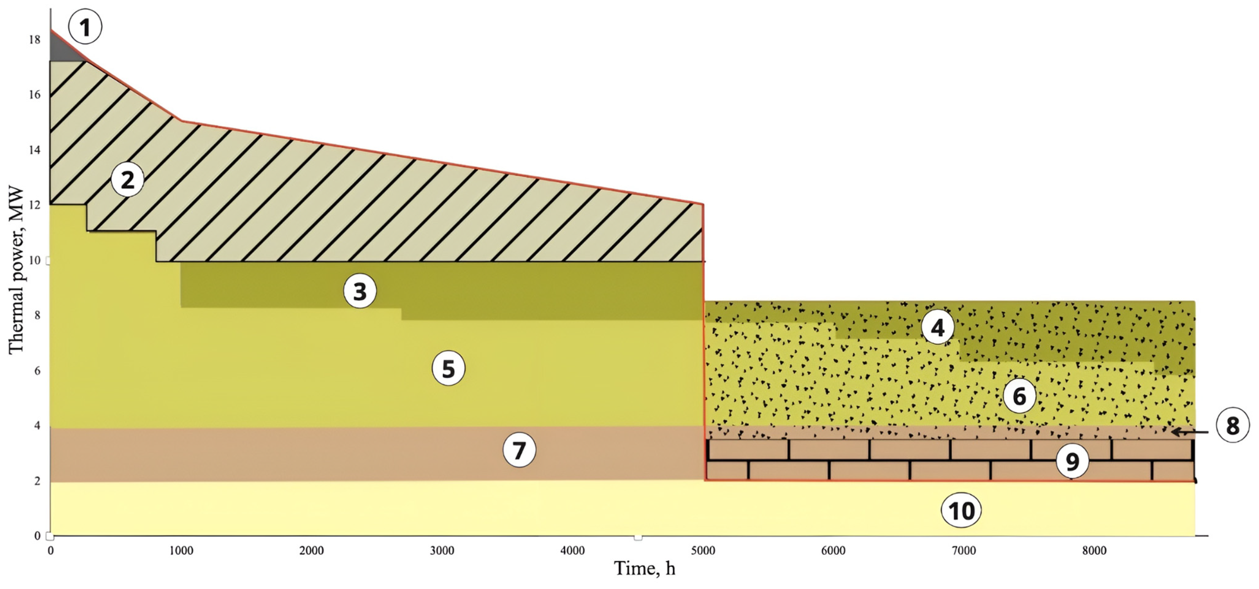
| Type of Energy Source | Capacity, MW | Energy Resource | Resource Volume |
|---|---|---|---|
| CHPP | 10 | Natural gas | 17,000 thousand m3 |
| Electrical boilers | 2 | Electrical energy | 17,500 MWh |
| Thermal energy storage | 6 | Thermal energy from CHPP | 18,000 MWh |
Disclaimer/Publisher’s Note: The statements, opinions and data contained in all publications are solely those of the individual author(s) and contributor(s) and not of MDPI and/or the editor(s). MDPI and/or the editor(s) disclaim responsibility for any injury to people or property resulting from any ideas, methods, instructions or products referred to in the content. |
© 2023 by the authors. Licensee MDPI, Basel, Switzerland. This article is an open access article distributed under the terms and conditions of the Creative Commons Attribution (CC BY) license (https://creativecommons.org/licenses/by/4.0/).
Share and Cite
Boyko, E.; Byk, F.; Ilyushin, P.; Myshkina, L.; Filippov, S. Approach to Modernizing Residential-Dominated District Heating Systems to Enhance Their Flexibility, Energy Efficiency, and Environmental Friendliness. Appl. Sci. 2023, 13, 12133. https://doi.org/10.3390/app132212133
Boyko E, Byk F, Ilyushin P, Myshkina L, Filippov S. Approach to Modernizing Residential-Dominated District Heating Systems to Enhance Their Flexibility, Energy Efficiency, and Environmental Friendliness. Applied Sciences. 2023; 13(22):12133. https://doi.org/10.3390/app132212133
Chicago/Turabian StyleBoyko, Ekaterina, Felix Byk, Pavel Ilyushin, Lyudmila Myshkina, and Sergey Filippov. 2023. "Approach to Modernizing Residential-Dominated District Heating Systems to Enhance Their Flexibility, Energy Efficiency, and Environmental Friendliness" Applied Sciences 13, no. 22: 12133. https://doi.org/10.3390/app132212133
APA StyleBoyko, E., Byk, F., Ilyushin, P., Myshkina, L., & Filippov, S. (2023). Approach to Modernizing Residential-Dominated District Heating Systems to Enhance Their Flexibility, Energy Efficiency, and Environmental Friendliness. Applied Sciences, 13(22), 12133. https://doi.org/10.3390/app132212133