Featured Application
Advanced thermo-mechanical tyre models, real time vehicle dynamic simulation, heat transfer calcualtion.
Abstract
Tyres are one of the most important elements of a vehicle because they are the link to the road and have a huge impact on traffic-related pollution. Knowing their behaviour, thus being able to use them at their best and reducing their wear rate, is one of the means of improving their lifetime, which means decreasing traffic environmental impact. In order to understand how tyres behave and to predict the real-time tyre–road coefficient of friction, which is strongly influenced by the temperature, in the last few years several complex thermo-mechanical models of heat transfer inside the tyre have been developed. However, in the current state of the art of the literature and practice, there is still an important parameter regarding such models that is not deeply studied. This parameter is the heat transfer coefficient between the tyre and the road at the contact patch, which usually is considered as a constant. The current research paper allows understanding that such an approximation is not always valid for all of the speeds and tyre loads of city and race cars; instead, it is developed an equation that, for the first time, calculates the real-time, dynamic tyre–road heat transfer coefficient, taking into account the tyre’s travelling speed and the footprint length. The equation results are in good agreement with the empirical values coming from the literature and permit understanding how much such a parameter can vary, depending on the tyre use range. The formulation is simple enough to be easily implemented in existing thermodynamic tyre models without requiring meaningful computational time.
1. Introduction
The tyre–road interaction is a fundamental element in the field of vehicle dynamics and plays a pivotal role in determining not only a vehicle performance but also its safety and energy efficiency (Rafei et al. [1]). A comprehensive understanding of this interaction is important because tyres are the ultimate link between the vehicle and the road, and they are the means of the main force exchanges, as underlined by Pacejka [2]. Being able to predict/simulate tyre behaviour in different conditions permits improving vehicle design and can be also a way, to a certain extent, to perform the road surface project, as it can be found in a review of various design guidelines carried out by Das [3]. Moreover, Zhang et al. [4] reported that tyre wear particle emissions are higher than those coming from the exhaust. Operating tyres outside the design temperature can accelerate the wear rate, as remembered by West [5], so deepening the knowledge of tyre behaviour permits optimizing their use, extending their lifetime and decreasing, in such a way, their environmental impact.
Historically, semi-empirical models such as the “magic formula” proposed by Bekker et al. [6] served as the foundational principles for tyre modelling. These models primarily focus on the kinematics of the tyre contact patch and are based on empirical data, providing essential insights into lateral and longitudinal tyre forces and slip behaviour. While these kinematic models have significantly improved our understanding of tyre–road interaction and are still used in vehicle dynamics design (see, for instance, Nguyen in refs. [7,8]), they are inherently limited in terms of capturing the complexities arising from heat generation and dissipation within the tyre.
As highlighted by Persson in ref. [9], friction between tyres and road is strongly influenced by temperature. Moreover, in addition to the friction coefficient (in its hysteretic and adhesion components, as inferred by Grigoriadis [10]), temperature affects the rolling resistance, as underlined by Ejsmont et al. in ref. [11], and when it is excessive it can be harmful for the integrity of the tyre, as stated by Marais et al. [12]. Thus, a paradigm shift occurred in the modelling domain, leading to the development of thermodynamic tyre models. These models incorporate the thermodynamic aspects of the tyre–road interaction by accounting for heat generation and dissipation within the tyre, particularly in the contact patch region. By considering the said phenomena, these models offer a more accurate representation of real-world tyre behaviour, especially under extreme conditions and during high-speed manoeuvres.
One of the first researchers that addressed the role of the temperature in friction behaviour in the modern era was Persson [9], who was also one of the winners of the Tire Technology International Awards for Innovation and Excellence in 2022 [13].
In such a context, it is worth remembering the extended studies of Farroni et al. [14] that, starting from the one-dimensional Thermo-Tyre model of De Rosa et al. [15], which is a simplified method devoted to determining the surface temperature of the rubber, developed the analytical-physical tri-dimensional model called “Thermo Racing Tyre” (TRT). Such a model takes into account all heat generation and flux exchange phenomena occurring inside the tyre. Allouis et al. [16] proposed a test procedure to evaluate the thermal diffusivity of tyres, to be used in the said TRT model, and even a further model called TRTLAb. Moreover, Farroni [17] developed the Tire/Road Interaction Characterization and Knowledge (TRICK) tool, which permits tuning the various models using the vehicle as a lab. Furlan et al. [18] provided an artificial neural network model to predict the friction coefficient, including a heat transfer model to calculate the tyre bulk temperature. Mavros [19] proposed a thermo-mechanical model based on an extensive study of the local flash temperature. Ebbot et al. [20] developed a model, based on finite element analysis (FEA), able to predict the thermal distribution inside the tyre at steady state. Lin et al. [21] developed a simulation procedure that combines dynamic mechanical tests and material tests in order to evaluate, through computer simulation, the temperature distribution. Even solid rubber tyres for aircraft have been studied. For instance, Chen et al. [22] developed a particular model from the thermo-mechanical point of view, acknowledging that the high heating of such parts of the airplane can threaten safety during the landing procedures.
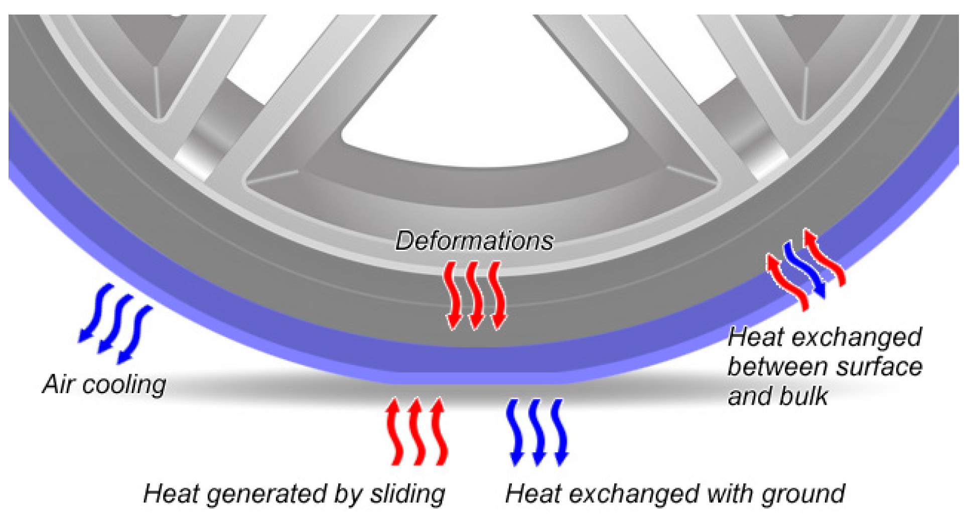
All of the above cited models, which depend upon the number of sub-systems into which the tyre is subdivided, calculate the heat transfer between the various parts by means of convection and conduction. It is worth mentioning that, usually, even advanced tyre models do not take into account any radiation thermal coefficient towards the external environment because it is considered negligible, as reported by Marais et al. [12]. The said heat transfer mechanisms considered are usually (Figure 1) represented by:
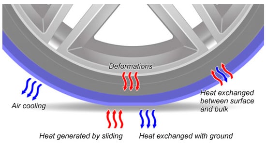
Figure 1.
Synthesis of heat transfer mechanisms between the tyre and the surroundings.
- (1)
- heat directly generated because of tyre deformations (mainly because of rolling resistance);
- (2)
- heat exchanged with external air by (forced) convection (tyre rolling at speed);
- (3)
- heat internally exchanged between rubber layers or other parts of the tyre;
- (4)
- heat directly generated in the surface layer by viscoelastic excitement of the polymer from rubber sliding over road asperities;
- (5)
- heat exchanged with the road at the contact patch, removed from the surface layer, which requires knowledge of the tyre–road heat transfer coefficient Hc.
Whereas the first four heat transfer mechanisms are well studied and discussed in the existing thermodynamic tyre models, the heat exchanged with the ground is vastly overlooked because information about the Hc coefficient is scarce and its actual value, which was obtained only in empirical ways, is not easy to find in the literature.
The Hc coefficient is important because it takes into account, in a macroscopic manner, the conduction heat transfer during the transitory time of contact between the tyre and the ground. By means of the said coefficient, the expression of the heat flux, φ [W], exchanged with the ground can be calculated with the Newton formula as follows:
where A [m2] is the tyre contact patch area and ΔT [K] is the temperature difference between the road and the surface of the tyre tread.
Usually, in the literature as well as in practice, the tyre–road heat transfer coefficient Hc is proposed as an empirical constant, as declared by Farroni et al. in ref. [23]. However, the (few) values published in the literature are very different one from another, suggesting that the actual value of Hc may depend upon the testing conditions. For example, Miller [24] suggested a value of 3 × 10⁴ W/m2K. Smith et al. [25] proposed one of the most used values, 1.2 × 10⁴ W/(m2K), employed, as it is, also by [26,27,28], without any discussion about its validity in relation to the testing conditions. Hackl et al. [29] found results significantly lower and around 2 × 10³ W/m2K. Taking into account the above discussion, the Hc range seems rather wide, suggesting that its expression should be more complex than a simple constant. To date, there is no evidence that the value 1.2 × 10⁴ W/(m2K), even if it is the most used, is the correct one, because as far as the authors’ knowledge goes, there is not an extensive validation of such a number for all of the possible tyre use conditions. Farroni et al. [30] considered Hc a function of the thermal characteristics of the compound only, but as far as the authors’ knowledge goes, there is not a relation or an equation that permits calculating the coefficient on the basis of known parameters related to actual vehicle conditions. There is a lack of knowledge about the phenomenon.
It is important to underline that the use of a constant for the Hc value is acceptable when two different materials are continuously in contact. Such a hypothesis is not verified in the case of a rolling tyre and the road, because the contact surface portion continues to change and the heat stored in each portion of the surface layer is continually released to the ground every tyre revolution. Thus, Hc is expected to show some dependency upon the tyre speed and footprint length.
As underlined by [17], the thermal real effects on tyres are often underestimated; nevertheless, the Hc impact can be very meaningful on modern thermodynamic models implementing it. Thus, its determination is an important open research question, which cannot be neglected in the complex evaluation of tyre behaviour.
The scope of the current paper is to answer such a question by developing a first proposal for an equation that allows evaluating the Hc coefficient.
The novelty of the paper consists in providing, for the first time, a dynamic formulation for Hc, based on physical principles of heat transmission, that takes into account not only the tyre compound characteristics but also the real-time speed of the vehicle and the tyre footprint length.
In order to achieve the declared scope, the paper is structured into the following sections:
- Section 2: An analysis of the theoretical heat transfer mechanism between the tyre surface and the road, based on energy conservation principles;
- Section 3: A physics-based equation describing the process;
- Section 4: A validation of the model on the basis of the few literature results available;
- Section 5: A discussion of the results;
- Section 6: Some considerations for future possible developments.
2. Heat Transfer between Road and Tyre—Thermophysical Aspects
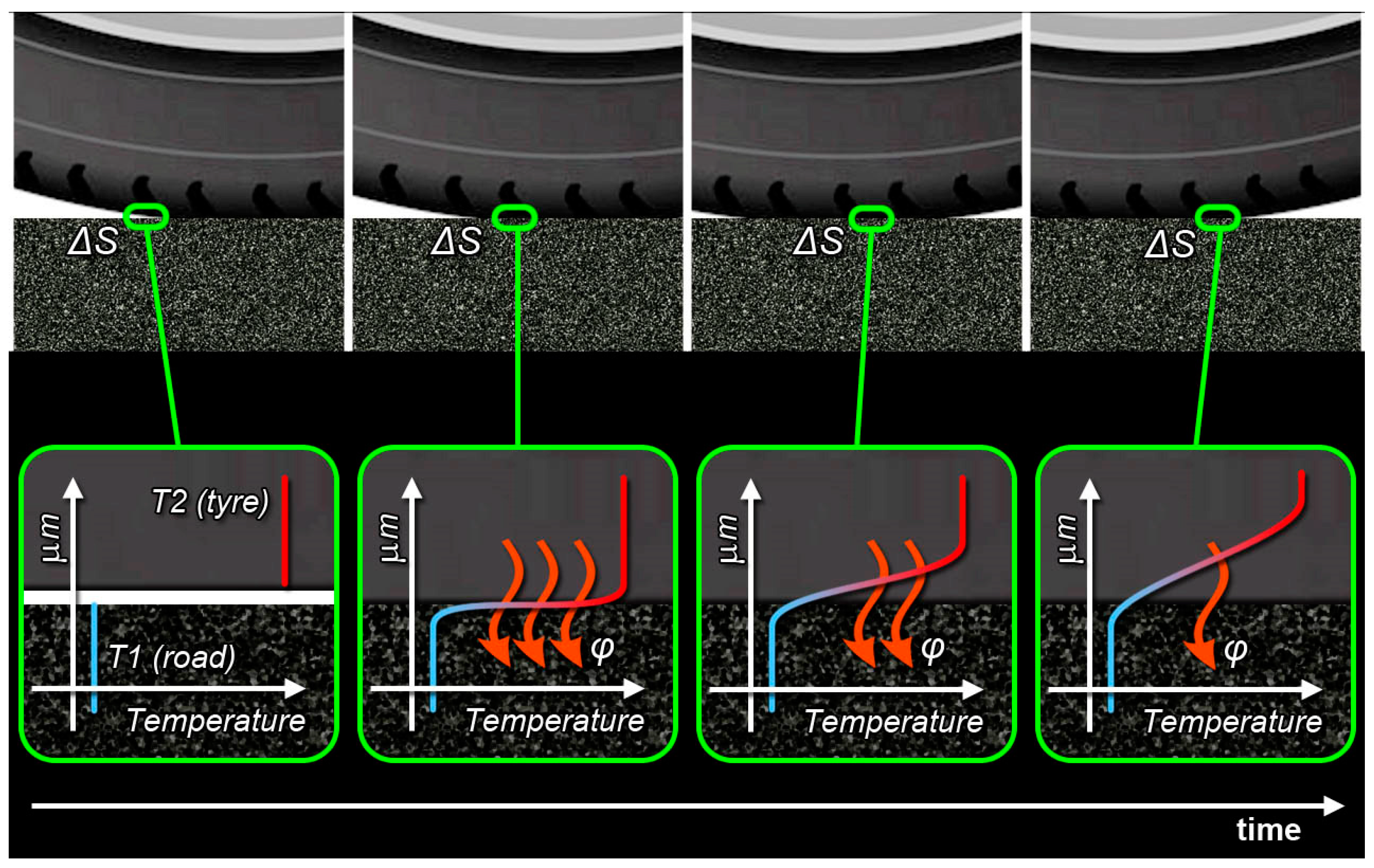
The tyre–road heat transfer mechanism is theorised starting from the description of what happens when the rolling tyre surface comes into contact with the ground and becomes part of the contact patch. In particular, the description takes into account a small part of the tyre tread surface ΔS [m2] and what happens inside the first infinitesimal layer of rubber in terms of the thermal gradient and thermal flux, φ, exchanged with the ground, as can be seen in Figure 2.
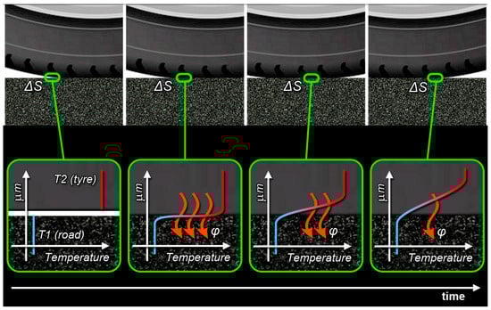
Figure 2.
Thermal gradient evolution inside the tyre due to the heat flux passing through the tyre surface ΔS.
Analysing Figure 2, it can be seen that, at first, the tyre and road surfaces have different temperatures, T1 [K], the road one, and T2 [K], the tyre one. Nevertheless, as soon as ΔS is pressed into contact with the ground, because of the tyre rotation, at least the very first molecular layer substrate must reach thermal equilibrium. In that situation, a steep thermal gradient develops inside the rubber surface ΔS, so an intense thermal flux, φ, starts to flow from the tyre surface to the ground [31].
Because of that intense thermal flux, the temperature of the first substrate drops, and this thermal drop begins to propagate deeper (it is worth noting that the thermal gradient develops inside a very short depth of the rubber surface layer tread). The heat propagation smooths the thermal gradient; consequently, the heat flow decreases. A Finite Element Method (FEM) simulation by Mavros [19] was in agreement with the above description. Furthermore, the road temperature remains almost the same, given that the asphalt conductivity, as well as its thermal capacity, is one order of magnitude higher than those of the tyre rubber, as reported by [32].
As soon as the surface area previously in contact with the ground loses such a contact, the temperature of the first layer rises again, returning in thermal equilibrium with the temperature of the rubber surface layer until ΔS, after a full tyre rotation, returns into contact with the ground. The whole process generates continually a heat loss that can be taken into account when defining the Hc coefficient. Such a coefficient permits calculating the heat flux passing from the tyre to the road on average (Equation (1)).
Considering the above description, Hc is not expected to be a constant but rather a function of the (rolling) tyre footprint–road contact time; in other words, the Hc coefficient should increase with the tyre rolling speed while decreasing with the footprint length, as hinted at also in ref. [29]. The above observation is the basis of the Hc equation development proposed in Section 3.
3. The Tyre–Road Heat Transfer Coefficient Hc Equation Proposal
As stated above, the Hc parameter should have a dependence upon the tyre rolling speed and the footprint length. In the current section, a formulation that takes into account such variables is proposed, starting from a simplification of the temperature gradient behaviour. The transient temperature gradient in the first infinitesimal tyre tread layer shows a shape like the one in Figure 2 [31], which can be approximated by a simplified polygonal curve, as depicted in Figure 3.
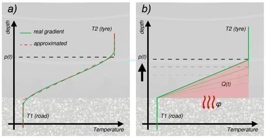
Figure 3.
(a) Temperature gradient approximation between the tyre tread surface and the road. (b) Heat exchanged between the tyre tread surface and the road as a function of the temperature gradient penetration.
In the above Figure 3, p(t) [m] is defined as the “propagation depth” of the temperature gradient: p(t) is the “knee” of the real curve gradient, and it represents the depth over which the temperature is still “undisturbed” and can be considered the one of the surface layer. Such a parameter p(t) is a function of time, equal to 0 at time t0 = 0, that corresponds to the instant at which the surface ΔS touches the ground, and then increasing monotonically as long as ΔS remains in contact with the road. The approximation in Figure 3 is based on the hypothesis that, given the short time of contact for a tyre rolling at speed, the length p(t) is very short as well, in comparison to the whole rubber thickness, and that the entire gradient is developing (happening) well inside the surface layer of the tyre rubber.
The heat stored inside the rubber is proportional to the reached temperature and the heat capacity. When the temperature decreases, it means that part of the stored heat is transmitted outside the tyre.
Taking into account the representation of the thermal gradient behaviour shown in Figure 3, it can be inferred that the amount of heat exchanged with the ground at time t [s], Q(t) [J], is proportional to the area of the triangle depicted in red in said figure. Thus:
Introducing the heat capacity per unit of volume, C [kJ/(m3K)], considered as a constant as in ref. [33], the energy lost by the rubber of the tyre surface ΔS at time t and transferred to the ground can thus be written as:
Given the heat flux definition:
Equation (3) can be derived as follows:
The heat flux going from the tyre to the road, however, must equal the heat flux inside the tyre rubber expressed by the Fourier thermal conduction law, considering the temperature gradient, the depth p and the heat conductivity coefficient, λ [W/(mK)] (assuming, as said above, that the asphalt conductivity is one order of magnitude higher than the rubber one):
From the comparison of Equations (5) and (6) comes:
Integrating the above differential equation with the boundary conditions p(t) = 0 when t = 0, it is possible to obtain, for p(t), the following expression:
Thanks to the above formulation, by comparing Equations (8) and (3), it is possible to express the amount of heat exchanged by the tyre surface ΔS and the ground as a function of the contact time t:
The above expression implies that Q(t0) = 0 because before any contact between the ground and tyre, no flux exchange with the ground happens.
Remembering Equation (4), the average heat flux exchanged can be expressed as the total amount of heat flowing during the whole time the surface ΔS is in contact with the ground divided by such an amount of time. Considering the interval of time Δt = tc − t0, where tc is the instant when the surface ΔS loses contact with the ground, it comes:
Remembering Equation (1), the average Hc can be expressed by dividing Equation (10) by the surface area ΔS and the temperature difference (T2 − T1):
Given the tyre footprint length FL [m] and the tyre speed v [m/s], it is straightforward to calculate the time tc as FL/v, and the final formulation of the real-time Hc heat transfer coefficient becomes:
The above equation is very easy to be applied, for instance, in existing thermodynamic tyre models. It allows determining the coefficient Hc as a function of two constant tyre compound characteristics (the heat conductivity coefficient, λ, and the heat capacity per unit of volume, C) and two dynamic variables: the rolling speed, v, and the footprint length, FL. These two variables can be easily determined by means of existing tyre models and/or by experimental results. The Hc formulation permits adding the real-time characteristic of the heat exchanged between the tyre and the road to those existing models.
In the next section, the validation of the proposed mathematical expression is carried out by comparing the literature results with the ones calculated using the equation.
4. Equation Validation
As already pointed out, as far as the authors’ knowledge goes, there are very few Hc values in the literature. Thus, in order to understand if the equation can be considered reliable, a test was carried out on the only available values. It must be underlined that in all of the literature cases, the boundary conditions were not very clear.
At any rate, considering a tyre conduction coefficient of 0.25 W/(mK), which is a diffused used value for tyres [12,34], and an average specific volume heat equal to 2 × 10⁶ J/(m3K) 121, Equation (12), with a speed of 41.6 m/s, equal to 150 km/h, for an FL equal to 0.14 [24], gives:
This result is in perfect agreement with [25]. The error of 1.6% can be considered completely negligible.
Taking into account the same tyre parameters but decreasing the rolling speed, for example, at 2.7 m/s, equal to 10 km/h, Hc becomes 3.1 × 10³ W/(m2K). Again, the parameters are in good agreement with the testing conditions and the results are of the same order of magnitude as those found in ref. [29].
It is interesting, in these cases, to calculate the maximum value of p(t) in order to validate the initial hypothesis that the thermal propagation depth is very thin in comparison to the whole tyre tread thickness. Remembering the expression of p(t) in Equation (8) and using for t the contact time FL/v, the above speeds give results in the range 10−5 m (v = 41.6 m/s, that is, 150 km/h) and 10−4 m (v = 2.7 m/s, that is, 10 km/h). Given an average rubber layer thickness in the order of magnitude of 3 × 10⁻² m [35], the initial assumption that the whole process happens only at the tyre surface layer can be considered confirmed and therefore validated.
Finally, it must be underlined that the Hc values, calculated using the equation, increase with speed. Such a result complies with empirical observations about the tyre temperature behaviour, such as that described by Hyttinen et al. [36].
Table 1 summarises the comparison between the literature values and equation results.

Table 1.
Comparison between the Hc literature values and Hc equation results.
5. Discussion
On the basis of the discussion in Section 4, it is possible to state that the equation provides results in the same order of magnitude as the values found in the literature in similar conditions. Thus, the study, as far as the authors’ knowledge goes, for the first time offers a theoretical justification for the use of the empirical values normally found in the literature and provides an explanation, mainly driven by the tyre rolling, for the wide range of them.
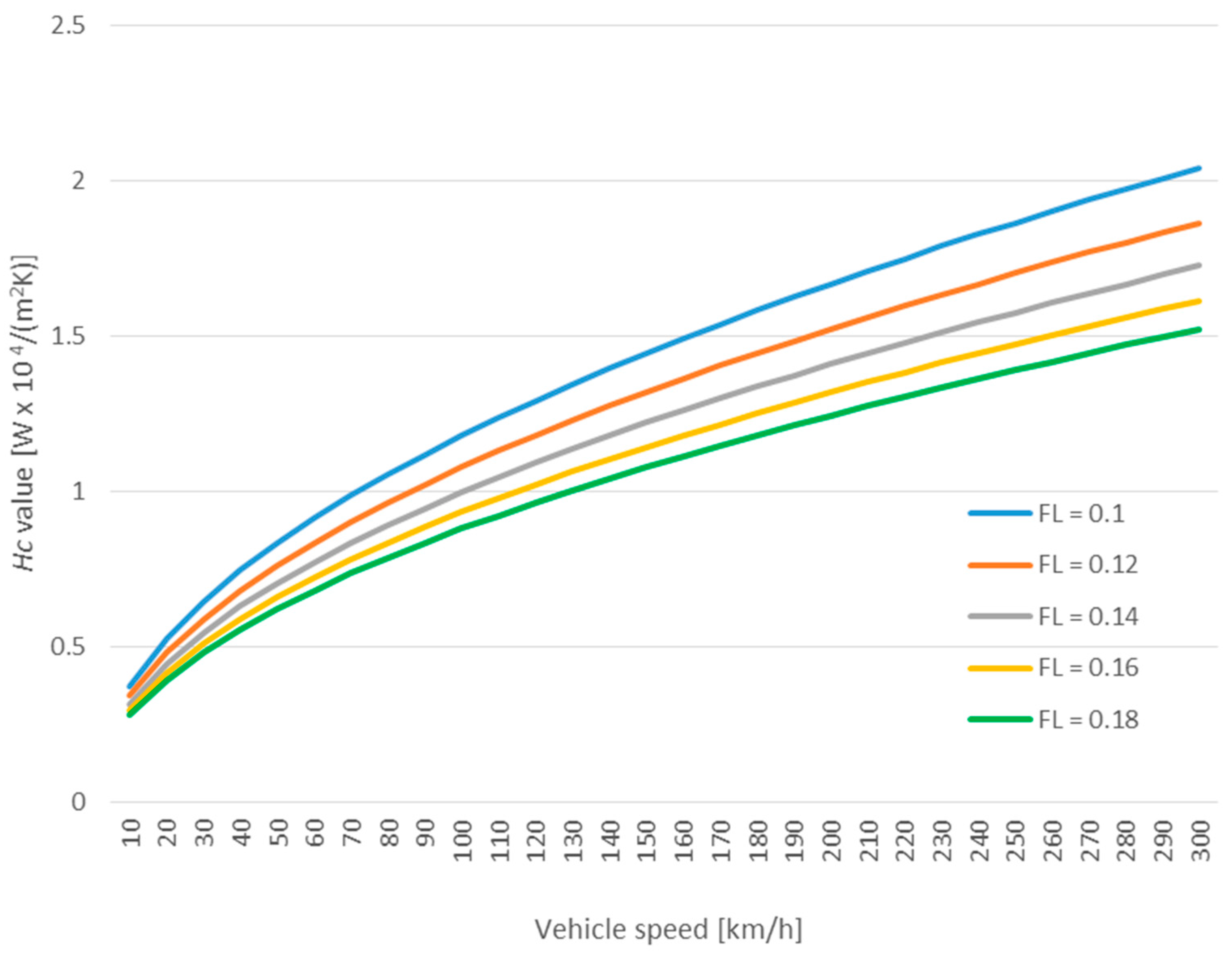
It is important to remember, even in this section, that one of most adopted values for Hc is 1.2 × 10⁴ W/(m2K) and that, in many models and papers, it is used without discussion about the boundary conditions. In particular, it is used without paying attention to the rolling speed of the tyre or to the wheel footprint length. It is worth noting that, on the basis of the equation analysis, as well as of the testing conditions of some of the users of such a number, it seems that the number should be suitable only for high speeds. In the graph in Figure 4, the Hc behaviour is parameterised as a function of the footprint length of 0.14 m and calculated as a function of the rolling speed, as expressed in kilometres per hour.
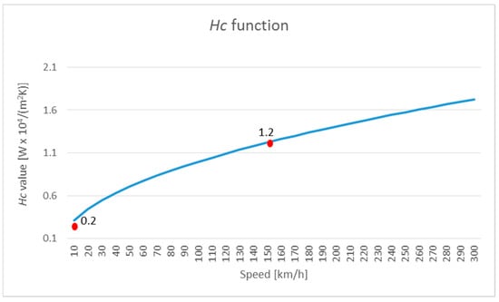
Figure 4.
Hc behaviour as a function of the rolling speed (footprint length of 0.14 m). Red dots represent the literature empirical values.
Analysing the graph above, it is clear that the most used value of Hc could be employed for a speed range between 100 km/h and 200 km/h, if a total error of 40% (±20%) can be considered acceptable. Such a range is certainly suitable for racing cars and, as a matter of fact, it must be recognised that many tyre models are focused on such a target. Nevertheless, if passenger cars and city speeds are considered, it seems more appropriate to halve the Hc values employed.
It is interesting to analyse, as well, what happens if the tyre load changes, influencing the footprint length. Regarding the FL evaluation, Balakina et al. [37] proposed an interesting work. The paper starts from the Hedekel formula reported below, which is derived from geometric considerations:
In the equation above, ∆z represents the radial tyre deformation [mm], while R is the free wheel radius [mm]. The gradient of z is given by the ratio between the normal wheel load P [N] and the radial rigidity of the tyre, R, [N/mm], as written below:
In said paper, Balakina et al., proposed a correction coefficient for Equation (13) in order to obtain the best fit between the empirical findings and the calculated ones. One of the most interesting parts of the work is that, in order to evaluate such a coefficient, several experiments were carried out, concerning both various types of passenger cars as well as trucks. For the current work, the very experimental results reported in Table 2 of ref. [37] were taken into account. Only passenger vehicles, characterised by a normal wheel load that goes from 1863 N to 3923 N, were considered. Here, 1863 N is about 750 kg, a typical mass for a small car, while 3923 N is about 1568 kg, a mass ascribable to a station wagon or small sports utility vehicle (SUV) [38]. The average free wheel radius was 0.3 m.
Table 2.
Hc analytical results for different vehicle speeds at different footprint lengths.
Table 2 of ref [37] permits inferring an FL range that goes from 0.1 to 0.18 for the said car range.
Taking into account Equation (12), considering a tyre conduction coefficient of 0.25 W/(mK) and an average specific volume heat equal to 2 × 10⁶ J/(m3K), it was possible to calculate the Hc values parametrised as a function of increasing the FL values, starting from 0.1 m, with an increment step of 0.02 m. The calculation was performed for increasing speeds in a range from 10 km/h to 300 km/h. The analytical results are reported in Table 2.

Figure 5.
Hc variation with the rolling speed as a function of different foot lengths.
Analysing Figure 5, it can be confirmed that the value of 1.2 × 10⁴ W/(m2K) remains suitable for high speeds: from 70 km/h, for the lightest footprint, related to very small cars, to 300 km/h, for the heaviest one. When low speeds are considered, it seems more adequate to use values one order of magnitude below. For example, it would be suitable to use 3.1 × 10³ W/(m2K) for a speed range from 50 km/h to 10 km/h, representing typical city speeds. Nevertheless, if, for example, an FL of 0.18 is considered, the value of 130 km/h could be the lowest threshold where 1.2 × 10⁴ W/(m2K) can be applied. Below such a speed, a lower Hc value should be considered. As a matter of fact, from the considerations above, an attentive Hc evaluation should not be a negligible step in the tyre thermal model definition. Actually, it must be remembered that the use of a completely wrong Hc provides, as a result, an unrealistic tyre behaviour, because such a coefficient should be able to offer an account of all of the heat discharged by the tyre through contact with the ground.
It Is worth remembering that the temperature of tyres is one of the main parameters ruling their consumption. Understanding how the thermal profile evolves in different speed ranges and load configurations is one of the means of improving tyre design and management. All of these actions are focused on improving safety and on minimizing consumption, thus decreasing tyre-related pollution.
From the computational point of view of an implementation of the proposed formula, it can be said that the equation only requires a square root, a division and a multiplication. It is clear that such operations add a negligible computation time in comparison to the use of a simple constant. Thus, in a complex thermodynamic tyre model, where it is important to achieve the most realistic results, adding this expression for Hc does not affect the computational time, while, at the same time, it can meaningfully improve the accuracy of the results. Authors have made a first experimental attempt to integrate said equation into the existing tyre model of the AVC™ virtual car simulation library [39], obtaining results more in compliance with the empirical results, without noticing significant additional computation time.
6. Further Developments
In order to better validate the model, in addition to the literature results, it is advisable to compare the theoretical results with new sets of empirical data directly collected for the purpose. The next step in the current research will be developed in this direction, collecting Hc values using real vehicles running on a specific track at different speeds and with different footprint lengths. Different tyre typologies will be tested too. The vehicles will be equipped with on-board instruments in order to collect the temperature behaviour of the external layers of the rubber, while the asphalt conductivity will be determined starting from its granular composition and compared to the tyre one to understand the approximation error entity of the proposed equation. The experiments will be carried out on sport cars in order to test the widest speed range possible.
Furthermore, the proposed equation will be implemented in a complex thermos-mechanical tyre model based on the interaction between the temperature dependant characteristics of the tyre compound and the power spectral density of the terrain asperities. Such a model is a further step in the research and it is currently in the final development phase.
7. Conclusions
The current paper proposes a novel, physics-based equation that serves the purpose of computing, in real-time, the dynamic tyre–road heat transfer coefficient Hc. This coefficient estimation relies on essential tyre compound characteristics and two dynamic parameters: the rolling speed of the tyre and the length of its footprint on the road. The work is motivated by the need to address a research question that has long been overlooked in this field: the lack of knowledge about the heat transfer coefficient between the tyre and the road. Despite its significant impact on the results generated by more intricate thermos-mechanical tire models, this parameter has historically been treated as a constant, even though the few values available in the literature exhibit significant variability, varying by more than one order of magnitude. This inconsistency has cast doubt on the suitability of these values for integration into advanced tyre models whose aim is to provide the most realistic results possible.
The equation presented in this paper was developed considering the mechanism of heat transfer that occurs between the ground and the first layer of the rubber composing the tyre tread. This heat transfer predominantly occurs within the tyre surface layer, specifically through the contact area. The formulation of Hc is based on the average heat flux exchanged between the tyre surface and the ground throughout a full revolution of the wheel.
To validate the proposed equation, comparisons with the values actually available in the existing literature were made. The results consistently demonstrated a close alignment with the empirical data. For instance, at high speeds of approximately 41.6 m/s (equivalent to 150 km/h) and a tire footprint length of 0.14 m, the proposed model provides a value of 1.22 × 10⁴ W/(m2K). Conversely, at lower speeds of 2.7 m/s (equivalent to 10 km/h), the equation yields a value of 3.1 × 10³ W/(m2K). These results support the theoretical justification for employing the empirical values that are commonly found in the literature.
Upon careful analysis of the equation outcomes and thorough consideration of the underlying physics, it becomes evident that Hc is not a constant throughout the entire spectrum of vehicle speeds. Specifically, this work emphasises that the most widely used value of Hc, which stands at 1.2 × 10⁴ W/(m2K), is most suitable within the medium- to high-speed range, spanning from 100 km/h to 200 km/h, with the tire footprint length set at 0.14 m. However, when vehicle speeds fall within the 10 km/h to 50 km/h range, it is more fitting to halve the aforementioned Hc value. For higher speeds, employing the widely disseminated Hc value could potentially lead to an underestimation of the actual heat exchanged with the ground.
An additional advantage of the formula Is Its simplicity and efficiency. It entails minimal computational overheads and can be seamlessly integrated into more complex tyre models, adding the needed real-time characterisation of the heat exchange between the tyre and the ground. This integration serves to refine the prediction of tyre behaviour, fostering smarter tyre design and utilisation that can effectively mitigate tyre-related pollution.
Looking ahead, this research will expand to encompass the validation of the equation using experimental data gathered from real vehicles operating at various speeds. Moreover, the aim is to incorporate the formula into a new comprehensive thermos-mechanical tyre model actually under development by the authors.
Author Contributions
Conceptualization, P.C., L.C. and A.M.; Methodology, P.C., L.C. and A.M.; Software, P.C.; Validation, P.C. and L.C.; Formal analysis, P.C. and A.M.; Investigation, P.C. and L.C.; Resources, A.M.; Data curation, P.C. and L.C.; Writing—original draft, P.C. and L.C.; Writing—review & editing, P.C., L.C. and A.M.; Visualization, P.C.; Supervision, A.M. All authors have read and agreed to the published version of the manuscript.
Funding
This research received no external funding.
Institutional Review Board Statement
Not applicable.
Informed Consent Statement
Not applicable.
Data Availability Statement
Data is contained within the article, no further data available.
Conflicts of Interest
The authors declare no conflict of interest.
Nomenclature
| Acronyms | |
| FEA | Finite Element Analysis |
| FEM | Finite Element Method |
| SUV | Sports Utility Vehicle |
| TRT | Thermo Racing Tyre |
| TRICK | Tire/Road Interaction Characterization and Knowledge |
| Symbols | |
| A | Contact area between tyre and road (m2) |
| C | Heat capacity per unit of volume (J/(kgK)) |
| R | Radial rigidity of the tyre (N/mm) |
| FL | Tyre footprint length (m) |
| Hc | Tyre–road heat transfer coefficient (W/(m2K)) |
| p(t) | Propagation depth (m) |
| Q(t) | Heat (J) |
| P | Normal wheel load (N) |
| S | Tyre surface (m2) |
| T | Dry bulb temperature (°C) |
| t | Time (s) |
| v | Tyre speed (m/s) |
| ∆z | Radial tyre deformation (mm) |
| λ | Conductivity coefficient (W/(mK)) |
| φ | Heat flux (W) |
References
- Rafei, M.; Ghoreishy, M.R.H.; Naderi, G. Thermo-mechanical coupled finite element simulation of tire cornering characteristics—Effect of complex material models and friction law. Math. Comput. Simul. 2018, 144, 35–51. [Google Scholar] [CrossRef]
- Pacejka, H.B. Tire and Vehicle Dynamics, 3rd ed.; Butterworth-Heinemann: Oxford, UK, 2012; ISBN 9780080970165. [Google Scholar] [CrossRef]
- Das, A. Structural Design of Asphalt Pavements: Principles and Practices in Various Design Guidelines. Transp. Dev. Econ. 2015, 1, 25–32. [Google Scholar] [CrossRef]
- Zhang, M.; Yin, H.; Tan, J.; Wang, X.; Yang, Z.; Hao, L.; Du, T.; Niu, Z.; Ge, Y. A comprehensive review of tyre wear particles: Formation, measurements, properties, and influencing factors. Atmos. Environ. 2023, 297, 119597. [Google Scholar] [CrossRef]
- West, W.J.; Limebeer, D.J.N. Optimal tyre management for a high-performance race car. Veh. Syst. Dyn. 2022, 60, 1–19. [Google Scholar] [CrossRef]
- Bakker, E.; Nyborg, L.; Pacejka, H.B. Tyre modelling for use in vehicle dynamics studies. In Proceedings of the Conference: Society of Automotive Engineers International Congress and Expo, Detroit, MI, USA, 23 February 1987. [Google Scholar]
- Nguyen, T.A. Establishing a novel adaptive fuzzy control algorithm for an active stabilizer bar with complex automotive dynamics model. Ain Shams Eng. J. 2023, 14, 102324. [Google Scholar] [CrossRef]
- Nguyen, T.A. Development of a Fuzzy Algorithm with Multiple Inputs for the Active Stabilizer Bar to Improve Vehicle Stability When Steering. IEEE Access 2023, 11, 29035–29047. [Google Scholar] [CrossRef]
- Persson, B.N.J. Role of Frictional Heating in Rubber Friction. Tribol. Lett. 2014, 56, 77–92. [Google Scholar] [CrossRef]
- Grigoriadis, K.; Mavros, G.; Knowles, J.; Pezouvanis, A. Experimental investigation of tyre–road friction considering topographical roughness variation and flash temperature. Tribol. Int. 2023, 181, 108294. [Google Scholar] [CrossRef]
- Ejsmont, J.; Taryma, S.; Ronowski, G.; Swieczko-Zurek, B. Influence of temperature on the tyre rolling resistance. Int. J. Automot. Technol. 2018, 19, 45–54. [Google Scholar] [CrossRef]
- Marais, J.; Venter, G. Numerical modelling of the temperature distribution in the cross-section of an earthmover tyre. Appl. Math. Model. 2018, 57, 360–375. [Google Scholar] [CrossRef]
- Tire Technology International Awards for Innovation and Excellence. Available online: https://www.tiretechnology-expo.com/en/awards-2023.php (accessed on 20 July 2023).
- Farroni, F.; Giordano, D.; Russo, M.; Timpone, F. Thermo racing tyre a physical model to predict the tyre temperature distribution. Meccanica 2014, 49, 707–723. [Google Scholar] [CrossRef]
- De Rosa, R.; Di Stazio, F.; Giordano, D.; Russo, M.; Terzo, M. Thermo tyre: Tyre temperature distribution during handling maneuvers. Veh. Syst. Dyn. 2008, 46, 831–844. [Google Scholar] [CrossRef]
- Allouis, C.; Farroni, F.; Sakhnevych, A.; Timpone, F. Tire thermal characterization: Test procedure and model parameters evaluation. In Proceedings of the World Congress on Engineering, London, UK, 29 June–1 July 2016; pp. 1199–1204. [Google Scholar]
- Farroni, F. TRICK-Tire/Road Interaction Characterization & Knowledge—A tool for the evaluation of tire and vehicle performances in outdoor test sessions. Mech. Syst. Signal Process. 2016, 72–73, 808–831. [Google Scholar] [CrossRef]
- Furlan, M.; Mavros, G. A Neural Network Approach for Roughness-Dependent Update of Tyre Friction. Simul. Model. Pract. Theory 2022, 116, 102484. [Google Scholar] [CrossRef]
- Mavros, G. A thermo-frictional tyre model including the effect of flash temperature. Veh. Syst. Dyn. 2019, 57, 721–751. [Google Scholar] [CrossRef]
- Ebbott, T.G.; Hohman, R.L.; Jeusette, J.P.; Kerchman, V. Tire Temperature and Rolling Resistance Prediction with Finite Element Analysis. Tire Sci. Technol. 1999, 27, 2–21. [Google Scholar] [CrossRef]
- Lin, Y.J.; Hwang, S.J. Temperature prediction of rolling tires by computer simulation. Math. Comput. Simul. 2004, 67, 235–249. [Google Scholar] [CrossRef]
- Chen, D.; Wu, J.; Su, B.; Cui, B.; Teng, F.; An, S.; Bai, Y.; Liu, X.; Liu, Y.; Wang, Y. Thermo-mechanical-abrasive coupling analysis of solid rubber tire under high-speed rolling. Wear 2023, 512, 204546. [Google Scholar] [CrossRef]
- Farroni, F.; Mancinelli, N.; Timpone, F. A Real-Time Thermal Model for the Analysis of Tire/Road Interaction in Motorcycle Applications. Appl. Sci. 2020, 10, 1604. [Google Scholar] [CrossRef]
- Miller, D.C. Thermal Conductance of ad Heat Generation in Tire—Pavement Interface and Effect on Aircraft Braking; Technical Note; National Aeronautics and Space Administration: Washington, DC, USA, 1976.
- Smith, R.E.; Tang, T.; Johnson, D.; Ledbury, E.; Goddette, T.; Felicelli, S.D. Simulation of Thermal signature of tires and tracks, Distribution Statement A. In Proceedings of the NDIA Group Vehicle Systems Engineering and Technology Symposium, Modelling and Simulation, Testing and Validation (MSTV) Mini Symposium, Warren, MI, USA, 14–16 August 2012. [Google Scholar]
- Jayme, A.; Al-Qadi, I.L. Thermomechanical Coupling of a Hyper-viscoelastic Truck Tire and a Pavement Layer and its Impact on Three-dimensional Contact Stresses. Transp. Res. Rec. 2021, 2675, 359–372. [Google Scholar] [CrossRef]
- Tang, T.; Johnson, D.; Smith, R.E.; Felicelli, S.D. Numerical evaluation of the temperature field of steady-state rolling tires. Appl. Math. Model. 2014, 38, 1622–1637. [Google Scholar] [CrossRef]
- Nguyen, T.-C.; Cong, K.-D.D.; Dinh, C.-T. Rolling Tires on the Flat Road: Thermo-Investigation with Changing Conditions through Numerical Simulation. Appl. Sci. 2023, 13, 4834. [Google Scholar] [CrossRef]
- Hackl, A.; Scherndl, C.; Hirschberg, W.; Lex, C. Experimental Validation of Various Temperature Models for Semi-Physical Tyre Model Approaches. IOP Conf. Ser. Mater. Sci. Eng. 2017, 252, 012009. [Google Scholar] [CrossRef]
- Farroni, F.; Russo, M.; Sakhnevych, A.; Timpone, F. TRT EVO: Advances in real-time thermodynamic tire modeling for vehicle dynamics simulations. Proc. Inst. Mech. Eng. Part D J. Automob. Eng. 2019, 233, 121–135. [Google Scholar] [CrossRef]
- Incropera, F.P.; Dewitt, D.P.; Bergman, T.L.; Lavine, A.S. Fundamentals of Heat and Mass Transfer; John Wiley & Sons Inc.: Hoboken, NJ, USA, 2007; pp. 283–290. [Google Scholar]
- Pan, P.; Wu, S.; Hu, X.; Liu, G.; Li, B. Effect of Material Composition and Environmental Condition on Thermal Characteristics of Conductive Asphalt Concrete. Materials 2017, 10, 218. [Google Scholar] [CrossRef]
- Ghoreishy, M.H.R.; Rafei, M.; Naderi, G. Optimization of the vulcanization process of a thick rubber using an advanced computer simulation technique. Rubber Chem. Technol. 2012, 85, 576–589. [Google Scholar] [CrossRef]
- Nyaaba, W.; Frimpong, S.; Somua-Gyimah, G.; Galecki, G. FEA Prediction of Off-Road Tire Temperature Distribution. In Proceedings of the Conference: Science in the Age of Experience, Boston, MA, USA, 23–25 May 2016. [Google Scholar]
- Rahman, J.; Shoukaku, Y.; Iwai, T. In Situ Rubber-Wheel Contact on Road Surface Using Ultraviolet-Induced Fluorescence Method. Appl. Sci. 2020, 10, 8804. [Google Scholar] [CrossRef]
- Hyttinen, J.; Ussner, M.; Österlöf, R.; Jerrelind, J.; Drugge, L. Truck tyre transient rolling resistance and temperature at varying vehicle velocities—Measurements and simulations. Polym. Test. 2023, 122, 108004. [Google Scholar] [CrossRef]
- Balakina, E.V.; Zadvornov, V.N.; Sarbaev, D.S.; Sergienko, I.V.; Kozlov, Y.N. The calculation method of the length of contact of car tires with the road surface. IOP Conf. Ser. Mater. Sci. Eng. 2019, 632, 012022. [Google Scholar] [CrossRef]
- Cuenot, F. CO2 emissions from new cars and vehicle weight in Europe; How the EU regulation could have been avoided and how to reach it? Energy Policy 2009, 37, 3832–3842. [Google Scholar] [CrossRef]
- The AVC Project. Real Time Simulation of Wheeled Ground Vehicles, Description. Available online: http://www.paolocattani.com/personal/avc/ (accessed on 18 September 2023).


Disclaimer/Publisher’s Note: The statements, opinions and data contained in all publications are solely those of the individual author(s) and contributor(s) and not of MDPI and/or the editor(s). MDPI and/or the editor(s) disclaim responsibility for any injury to people or property resulting from any ideas, methods, instructions or products referred to in the content. |
© 2023 by the authors. Licensee MDPI, Basel, Switzerland. This article is an open access article distributed under the terms and conditions of the Creative Commons Attribution (CC BY) license (https://creativecommons.org/licenses/by/4.0/).