Abstract
A double-plunger type overspeed protection mechanism has excellent performance in turbine overspeed protection, but the complicated operating principle thereof makes long-term use difficult. In this study, a dynamic model is established to explain the relationship between the motion state and the force situation. Through the analysis of the dynamic model, the specific process of the linked plunger for achieving overspeed protection with tripping action is determined, and the motion law of the inner and outer plungers is clarified. Additionally, the complete solution method and calculation procedure for the tripping speed of the submerged plunger are established, and the specific process for solving the relevant equations with numerical iteration is clarified. Finally, a rigid-flexible coupling virtual prototype model is established, which validates the conclusion that initial eccentric distance and spring stiffness are key factors affecting tripping speed and the motion process of inner and outer plungers.
1. Introduction
The main shaft of a turbine rotates with a centrifugal force proportional to the square of the angular velocity. Once the design speed is exceeded, there is a high risk of damage to the unit and serious accidents [1]. Therefore, the overspeed protection device is of great importance for ensuring the safe operation of the turbine unit for a long time. There have been many studies on turbine overspeed protection devices, but the focus has been on electronic trip systems, which use speed sensors and electrical circuits [2,3,4]. For example, an electromagnetic system is used to monitor the system’s operating status in real-time [5], and the timing of starting the overspeed protection program is determined by judging the current operating conditions. Mechanical overspeed protection devices usually use centrifugal force at high rotational speeds to drive the mechanism to generate tripping action. However, mechanical overspeed protection has the situation of “mal-operation” or “refused operation of protection” [6], which is more evident in traditional single-plunger type overspeed protection mechanisms. Compared with the traditional single-plunger type, the double-plunger type can act more promptly and accurately when the unit is running overspeed, has a more stable performance at higher speeds, and can adjust the trip speed by changing the position of the outer plunger. Additionally, compared to other principle-based overspeed protection devices such as electromagnetic and hydraulic types, the mechanical type can work in a liquid environment, is easier to disassemble, does not need to provide power during operation, and can still work in the case of loss of external power supply [7]. However, the motion process and force conditions of the double-plunger type overspeed protection mechanism are also more complicated than those of the traditional single-plunger type, which makes it difficult to directly obtain the corresponding relationship between the structural parameters and trip speed and adds challenges to the design and widespread use of this device. In actual use, the corresponding relationship between the adjustment value and the trip speed has to be determined by repeated tests, which not only consumes considerable manpower but also reduces the operating efficiency of the turbine unit.
The objective of this study is to establish the equations of the dynamics of the inner and outer plungers and further explore the mechanism of the plunger to achieve the overspeed protection function, clarify the motion process of the inner and outer plungers, and verify it by simulation.
2. Device Operation Principle
The basic structure of the double-plunger type is shown in Figure 1.
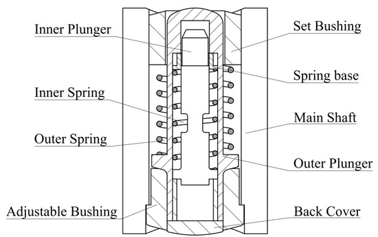
Figure 1.
Structure of double-plunger type overspeed protection mechanism.
The entire device is placed in a radial through hole in the main shaft, and the device can only move along the radial direction of the main shaft. The set bushings and adjustable bushings are attached to the main shaft with threads. In the initial state, the outer spring is in a compressed state, the outer flyweight is pressed by the outer spring on the lower cock, and the displacement is limited. By adjusting the depth of the adjustable bushing screwed into the main shaft, the overall height of the plungers can be adjusted. Compared with the traditional single-plunger type overspeed protector [8], the outer plunger is a cavity, and the inner plunger, inner spring, and spring base can be placed in the cavity of the outer plunger. The back cover and the outer plunger are integrally connected by threads, and the inner spring is in a compressed state at this time, which can limit the movement of the inner plunger.
Figure 2 shows the whole system in the complete state in (a), the main shaft cut state in (b), and the outer plunger cut state in (c).

Figure 2.
(a) Orthographic projection; (b) half-section view; (c) complete cut view.
As shown in Figure 3, since the center of mass of the inner plunger does not coincide with the center of rotation of the spindle when the main shaft starts to rotate, the inner plunger is subjected to centrifugal force. When the rotational speed reaches a critical value, the centrifugal force of the inner plunger overcomes the spring force to extend outward, which causes the eccentricity of the overall center of mass of the whole device to further increase. Subsequently, the outer plunger overcomes the spring force to fly out, and the extended plunger hits the lever mechanism to create subsequent actions, which then finally leads to the main shaft stopping.

Figure 3.
(a) Center of mass distribution; (b) hitting the leveraging mechanism.
3. Dynamic Modeling of Plungers
3.1. Analysis of Plunger Motion States
In the dynamics of multibody systems, to describe the motion of each object accurately, it is necessary to establish a suitable coordinate system based on its connections and constraints [9]. As shown in Figure 4, the absolute coordinate system, i.e., the fixed coordinate system ox0y0z0, and the relative coordinate system, i.e., the dynamic coordinate system oxyz, which is attached to the main shaft, are established. The x-axis of the dynamic coordinate system coincides with the axis of the turbine main shaft and is defined as the axial direction, and the z-axis of the dynamic coordinate system is defined as the radial direction. The basis vectors along the z and y axes in the dynamic coordinate system are eρ and eθ, respectively. In this study, the spindle only has rotational motion around its axis; relative rotation around the x-axis between the relative and absolute coordinate systems occurs; and the angle between the y0-axis in the absolute coordinate system and the y-axis in the relative coordinate system is θ. The angular velocity of the spindle rotation is ω = .

Figure 4.
Coordinate systems: (a) absolute coordinate system; (b) relative coordinate system.
After analyzing the constraints between each component, it can be seen that the inner and outer plungers have two degrees of freedom, and the compound motion of the inner plunger consists of two parts: the rotation around the axis along with the spindle, denoted as θ, and the radial movement along the y-axis of the dynamic coordinate system in the outer plunger cavity, denoted as ρ2. Similarly, the compound motion of the outer plunger consists of two parts: the rotation following the spindle, which is at the same angle as the rotation of the inner plunger and therefore also θ, and the radial movement inside the spindle bore cavity, denoted as ρ1. The moving points C1 and C2 are defined as the centers of mass of the outer and inner plungers, respectively; their radius vectors to the origin O in the absolute coordinate system are defined as r1 and r2, and the radius vectors to the origin in the relative coordinate system are defined as ρ1 and ρ2, respectively. The coordinate transformation matrix from the fixed coordinate system to the dynamic coordinate system is A. Then, the equations of motion of the plungers can be expressed as
where r and ρ are matrices with three rows and two columns.
It is clear that matrix A satisfies AAT = I, i.e., A−1 = AT, which means that it is an orthogonal matrix [10]. Therefore, ρ can be expressed as
To find the velocity of motion of the center of mass, Equation (1) is derived with respect to time:
Matrix is discussed next, with derivatives for time t on both sides of the equation AAT = I:
which means
This shows that matrix is an antisymmetric matrix whose diagonal elements are all zero and whose only three elements are independent. Therefore, it can be written in the following form:
It is clear that matrix is the skew-symmetric matrix of the vector ω = [ωx ωy ωz]T, denoted as . Substituting this into Equation (3) yields
where is the velocity vector of moving point C in the relative coordinate system and is its velocity vector in the absolute coordinate system. Then, the absolute velocity of the center of mass of the inner plunger is
To find the acceleration of the movement of moving point C, Equation (8) is derived for time:
Defining the rate of change of the vector in time with respect to the fixed coordinate system as the absolute derivative and the rate of change in time with respect to the dynamic coordinate system as the relative derivative, the last term in Equation (9) becomes the absolute derivative of the relative velocity vector. Since the absolute derivative of a vector is equal to its relative derivative plus the cross product of the angular velocity of the dynamic system and this vector [8]; therefore,
Substitute Equations (8) and (10) into Equation (9) yields
where is the acceleration of the dynamic system with respect to the fixed system, i.e., the convective acceleration; is the Coriolis acceleration [11]; is the acceleration of the moving point with respect to the moving system, i.e., the relative acceleration. It can be seen that the acceleration of a plunger in motion is a vector sum of the above three accelerations. The complex motion of an object in space can be described as a linear combination of basis vectors by establishing multiple basis vectors [10], each of which usually represents a certain characteristic direction of the object during its motion. In this study, the basis vectors eθ and eρ are established along the tangential and radial directions of the main shaft, respectively. Then, the convective acceleration for the inner plunger is
the relative acceleration is
the Coriolis acceleration is
Similarly, the acceleration of the outer plunger during the motion is
3.2. Analysis of the Plungers Force Situation
During the entire motion, the inner plunger may be subjected to the contact force Ft2 along the tangential direction of the spindle, the contact force Fr2 along the radial direction of the spindle, the frictional force f2, and the elastic force S2 generated by the inner spring and the outer plunger. These forces always satisfy the following equations:
Similarly, the outer plunger may be subjected to a contact force Ft1 along the tangential direction of the spindle, a contact force Fr1 along the radial direction of the spindle, a frictional force f1, an elastic force S1 generated by the outer spring, and an elastic force S2 generated by the inner spring. These forces always satisfy the following equations:
The force on the plungers is different when they are in different positions. As shown in Figure 5, there are three main cases for an inner plunger, as follows.
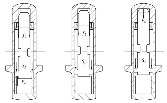
Figure 5.
Three different force conditions of the inner plunger.
When the inner plunger is located in the initial position, at which time , Equations (16) and (17) can be rewritten as
When the inner plunger moves inside the outer plunger cavity and its upper and lower end surfaces are not in contact with the inner wall of the outer plunger, the outer plunger does not produce a contact force along the radial direction of the main shaft, Fr2 = 0. At this time, Equation (16) is written as follows:
When the inner plunger moves to the outermost end, its upper surface comes into contact with the top surface of the inner wall of the outer plunger, and there is no relative motion between the inner and outer plunger. At this time, the outer plunger and inner plunger can be seen as a whole and Equation (16) can be written as follows:
Similarly, as shown in Figure 6, there are two cases of forces on the outer plunger, as follows.

Figure 6.
Two different force conditions of the outer plunger.
When no action occurs, similar to the inner plunger, , and Equations (18) and (19) are written as
With the outer plunger action, due to the outer plunger action and the adjustable bushing out of contact, the adjustable bushing on the radial contact force along the spindle disappears. At this time, Fr1 = 0, and Equation (18) is rewritten as follows:
4. Analysis of the Trip Process
4.1. Trip Speed of Plungers
When the rotation speed keeps rising to the preset tripping speed, there may be two kinds of movements of the inner and outer plungers, as follows.
- (1)
- The inner plunger moves first in the outer plunger cavity, and the outer plunger does not move at this time.
- (2)
- The outer plunger drives the inner plunger to move both plungers together. Because the bottom of the inner plunger is limited by the outer plunger base’s ability to move downward, there is no situation in which the outer plunger moves but the inner plunger remains in the same place.
To confirm the actual motion for the given parameters, the spindle speed can be calculated by calculating the centrifugal force required to overcome the spring force at the initial position of the inner and outer plungers for the action to occur. The spindle speed is used as the unknown to solve the following two sets of equations.
The spring forces S1 and S2 are calculated according to the following equation [12]:
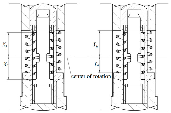
Figure 7.
Position description of Xa, Xb, Ya, and Yb.
For the problems of the centrifugal force on the spring in the rotating system, some scholars conducted relevant studies but did not propose a clear formula [13]. In this study, we followed the aforementioned research results to use Equations (28) and (29) and verified the equations as described in Section 5.
Using the algorithm in Section 4.1 to solve the above equation, can be obtained, which means that the action speed of the inner plunger is less than that of the outer plunger, and when the spindle speed keeps rising, the inner plunger first reaches the critical state of imminent flying out, which is categorized as the first case mentioned above. The at this time is recorded as ω2, which is the minimum speed to make the inner plunger action occur.
Because the inner plunger is moved after causing the inner spring to be further compressed, the elastic force S1 of the inner spring is also increased, and the force situation is changed; thus, it is necessary to re-determine whether the outer plunger will move after the spring force of the inner spring is increased. When the inner plunger is moved, the inner spring force is a function of the radial displacement ρ2 of the inner plunger, denoted as S2(ρ2). If the inner spring force is sufficient to overcome the frictional resistance and centrifugal force to make the outer plunger fly out, then there is
According to the calculation of the relevant parameters, Equation (30) does not hold when r0 < ρ2 < r0 + xmax. Therefore, the outer plunger does not produce radial displacement during the movement of the inner plunger. When the inner plunger moves to the end, the inner wall of the outer plunger is in contact, and the inner and outer plungers become a whole. At this time, the plunger action occurs under the following conditions:
This means that the centrifugal force overcomes the frictional force between the outer plunger and the bushings and the spring force to make the inner plunger fly out along with the outer plunger. Since the eccentricity of the inner and outer plungers is ρ2 = r0 + xmax, the centrifugal force on the whole plunger is greatly increased, so ω1 < ω0, the value of the left polynomial in Equation (31) is smaller than that of the right polynomial, and the whole outer plunger flies outward.
After the inner plunger moves in the cavity, its eccentricity increases further and the centrifugal force on it increases at the same time, but the spring is also further compressed and the spring force on it increases further. Therefore, the combined external force on the inner plunger is a function of ρ2, denoted as F2(ρ2).
After numerical calculation, F2 increases monotonically with the rise of the eccentricity ρ2 and the rotational speed ω, i.e., the combined external force on the inner plunger increases continuously and always points to the direction of motion. Therefore, the motion law of the inner plunger after the action occurs is to continuously accelerate along the radial direction of the spindle until it comes into contact with the inner wall of the outer plunger. Additionally, at this time, the motion of the inner plunger satisfies Equation (26).
When the inner plunger moved to the end and made contact with the outer plunger, the two had no relative motion; at this time, they could be seen as a whole. At this time, the external force on plungers can be expressed as
We can see that Equation (33) is greater than 0 at this time through numerical calculation; therefore, the outer plunger will fly out with the inner plunger together at this time.
In summary, the movement law of the inner and outer plungers states that after reaching the critical speed, the inner plunger starts to accelerate the movement. In this process, the outer plunger does not experience radial displacement. When the inner plunger and the inner wall of the outer plunger come into contact, the inner and outer plungers become whole and fly out together.
4.2. Motion Time of Plungers
Because the spindle speed is still changing after the action of the plunger occurs, the time interval between the action of the inner and outer plungers needs to be calculated to finally determine the time when the plunger completes the tripping action and obtain the final tripping speed according to the angular acceleration of the main shaft. The inner plunger in the outer plunger cavity performs a variable acceleration motion with the combined external force to meet Equation (32). Then, the kinetic energy of the inner plunger distance after the movement of x is as follows [14]:
From the set of Equation (34), the velocity of the inner plunger in this position can be expressed as
The average speed of the inner plunger during the whole motion is
According to Equations (34)–(36), can be expressed as
The time spent by the inner plunger during its trip process is
After the inner plunger movement to the outermost side (ρ2 = r0 + xmax), at this time the inner and outer plungers can be seen as a whole, similar to the inner plunger, and the movement time consumption of the whole plunger can be calculated using the same method. Therefore, the outer plunger movement time consumption is
The final trip speed can be obtained with the following equation:
5. Numerical Solution of the Dynamic Model
5.1. Processes of Solving
The computational process for the dynamic model of the inner and outer plungers can be represented as shown in Figure 8.

Figure 8.
Flowchart of computing: (a) the process of trip speed computing; (b) the process of the inner plunger’s trip speed.
First, it is necessary to calculate the minimum rotational speed ω2 that causes the action of the inner and outer plungers to occur at the initial position. Second, given that there is no analytical solution for the set of equations used to solve the rotational speed of the inner plunger tripping in Equation (37), the value of the rotational speed that satisfies the condition is solved with the numerical iterative method. Figure 8a shows the whole process of iterative calculation, in which the accuracy of the iterative calculation is set to 0.01 and the iterative process stops when the difference between the calculated result and the target value is less than 0.01.
Figure 8b shows the process of solving the motion time consumption of the inner and outer plungers using the relevant equations in Section 3. The average speed expression calculated according to Equation (37) is complicated and cannot be directly solved for its original function to perform integral operations, so the calculation result of Equation (37) is calculated with numerical integration, after which the final tripping speed of the plunger as a whole can be found according to Equation (40) in combination with process 1.
5.2. Results and Discussion
The centrifugal force generated by the main shaft driving the rotation of the inner plunger is the driving force that causes the eccentric motion of the inner plunger, while the pre-compression of the inner spring provides the resistance to stop the movement of the inner plunger, so the action speed of the inner plunger is primarily determined by the following two factors:
- (1)
- The pre-compression force provided by the inner spring;
- (2)
- The eccentricity of the center of mass of the inner plunger relative to the center of rotation of the main shaft.
After executing the process shown in Figure 8b, the calculation result is shown in Figure 9. The condition-satisfying ω2 is obtained at the iteration up to i = 10 times, and the computation converges here.

Figure 9.
Result of flow path b.
The calculation results of the time spent on the movement of the inner and outer plungers are shown in Figure 10.

Figure 10.
Result of flow path a.
As the number of selected data points increases, the step size of each calculation gradually decreases, and the final integration value gradually converges. The joint between the inner and outer plungers is categorized as a translation joint with dry clearance. For the movement trend between the inner and outer plungers, the friction force generated by the dry friction between the two is not a constant value [15]. This part of the friction situation can be further discussed in future research by analyzing the factors affecting the friction force of dry friction with clearance to establish a model for the change of friction coefficient between the inner and outer plunger and finally clarify the change law of the friction force.
6. Dynamic Simulation and Validation
6.1. Elasticity Calculation Formula Verification
The spring force calculation of Equations (28) and (29) for the spring in the rotating regime is verified with a simulation. As shown in Figure 11a, a flexible body model of the spring is given a load condition in the simulation software with both ends fixed and rotating around a certain axis while ensuring that the material parameters such as density, Young’s modulus, and Poisson’s ratio of the spring are consistent with the actual situation. By measuring the pressure at the fixed end, the spring force in the rotating condition can be obtained.

Figure 11.
(a) Stress distribution of a spring with centrifugal force; (b) result of simulation and theoretical calculation.
The simulation results are shown in Figure 11b. The speed of rotation and the position of the center of rotation are changed, the simulation results are measured, and the results are consistent with the theoretical equations, which verify the correctness of Equations (28) and (29).
6.2. Simulation of the Trip Process
Validation experiments using turbine units are too expensive and time-consuming to compete. In this study, simulation experiments are chosen to verify the correctness of the theoretical analysis [16]. Furthermore, we use the dynamics module in ADAMS to simulate the whole process of the overspeed protection system. Similar to the common process of using ADAMS for mechanism motion simulation [17], we set up constraints, loads, and motion subsets for the imported physical model in ADAMS, and we set up sensors to obtain motion parameters.
Figure 12 shows the model of the overspeed protection system in ADAMS.

Figure 12.
Model in ADAMS.
Because the eccentricities of each part of the inner and outer springs are different during the motion of the plunger, the magnitude of the centrifugal force is also different. The resulting inhomogeneous deformation changes the spring’s mass distribution, and the centrifugal force changes with the change in mass distribution. Therefore, although the reaction force that varies linearly with the displacement of the constrained end can be achieved by setting a spring-damper force in ADAMS, to accurately simulate the actual spring force in the rotating system, the spring needs to be imported into the simulation model and defined as a flexible body. In this study, the modal neutral file is generated using the Ansys workbench, and the .mnf file is used to generate the modal neutral file and provide the mesh and stress information in ADAMS to realize the flexibility of the spring. In the multibody system dynamics simulation environment, the pre-compression condition of the spring cannot be set, and the spring force used to hold the plunger in place is simulated by defining the force acting directly on the plunger after the inner and outer springs are pre-compressed.
The spindle is driven with uniform acceleration, and the displacement of the outer plunger along the Z-axis direction of the spindle is used as the condition for the simulation process to stop. Specifically, the simulation process stops when the outer plunger flies outward by more than 1 mm. According to the acceleration value and the spindle acceleration time consumption, the final speed of the spindle can be obtained when the outer plunger hits the leveraging mechanism.
Figure 13a shows the speed-displacement curve of the inner and outer plungers along the radial direction of the main shaft.
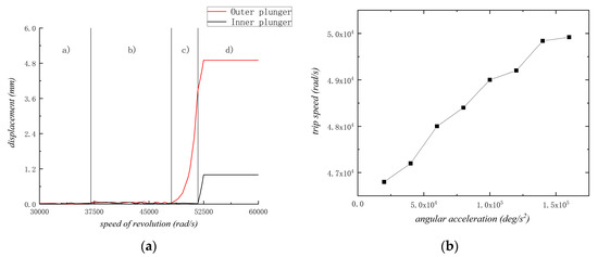
Figure 13.
Results of simulation: (a) speed–displacement curve of the inner and outer plungers; (b) trip speed change curve of the inner plunger.
The horizontal coordinate of Figure 13a is the rotational speed of the spindle, and the vertical coordinate is the displacement of the inner or outer plungers along the radial direction of the spindle relative to the initial position. The motion process is divided into the following four stages:
- (a)
- The spindle speed is low, and the inner and outer plungers are not displaced.
- (b)
- The spindle speed is gradually approaching the inner plunger trip speed, and the inner and outer plungers show an unstable state, resulting in a small displacement (less than 0.1 mm).
- (c)
- The inner plunger overcomes the spring resistance with the driving of centrifugal force and starts accelerated motion, and the outer plunger does not move in this process.
- (d)
- The inner plunger moves to the end and comes into contact with the top of the inner wall of the outer plunger, and then both inner and outer plungers fly outward together.
As shown in Figure 13b, the final tripping speed of the plunger increases with acceleration, and the trend is consistent with the results of the theoretical model.
As shown in Figure 14, trip speed grows with spring stiffness, and the inner plunger trips at a higher speed over a shorter eccentric distance.

Figure 14.
Trip speed of inner plungers in different eccentric distance.
In summary, the simulation of the plunger motion is consistent with the theoretical analysis.
7. Conclusions
In this study, the relationship between the acceleration of the plunger in motion and its position, spindle speed, eccentric distance, and other parameters was determined. The inner plunger first moved radially along the main shaft with the action of centrifugal force until it came into contact with the inner wall of the outer plunger, and then the inner and outer plungers flew outward together to produce the tripping action. The formula for calculating the rotational speed of the inner plunger and the formula for calculating the time required for the movement of the inner plunger in the outer plunger cavity were derived.
A rigid-flexible coupling virtual prototype model was established with ADAMS and ANSYS. The entire process of plunger motion was simulated with a dynamics simulation to verify the correctness of the plunger action mechanism in the theoretical model, and the variation of the inner plunger action speed with the initial eccentric distance and spring stiffness was demonstrated.
The action speed of the inner plunger was the key factor for determining the spindle speed when the whole plunger tripped; the action speed of the inner plunger was primarily affected by its initial state eccentricity and inner spring stiffness.
Author Contributions
H.J. designed the study and wrote the first draft of the manuscript. D.W. developed the overall framework for the article and provided language support. H.J. and P.C. analyzed the dynamic process, derived formulas, and designed the algorithm. H.J. and C.S. conducted the simulation and analyzed the results. All authors have read and agreed to the published version of the manuscript.
Funding
This research was funded by “Construction of common technology research and development, testing and application platform projects for basic machinery and key components” grant number [2021-0170-1-1].
Institutional Review Board Statement
Not applicable.
Data Availability Statement
The data presented in this study are available on request from the corresponding author. The data are not publicly avaliable due toethical restrictions.
Acknowledgments
The authors thank China Productivity Center for Machinery and China Academy of Machinery Science and Technology Group Co. Lid for their financial support.
Conflicts of Interest
The authors declare that this study received funding from China Productivity Center for Machinery and China Academy of Machinery Science and Technology Group Co. Lid. The funder was not involved in the study design, collection, analysis, interpretation of data, the writing of this article or the decision to submit it for publication.
Nomenclature
| mh2 | Inner plunger mass |
| mh1 | Outer plunger mass (including locating bushings) |
| ms2 | Inner spring mass |
| ms1 | Outer spring mass |
| k2 | Inner spring stiffness |
| k1 | External spring stiffness |
| xmax | Maximum displacement of the inner plunger relative to the outer plunger |
| H | Maximum displacement of the outer plunger relative to the main shaft |
| d1 | Distance between the center of mass of the outer plunger and the center of rotation |
| r0 | Eccentricity of the inner plunger in the initial state |
| l2 | Pre-compression length of the inner spring |
| l1 | Pre-compression length of the outer spring |
| R1 | Overall eccentricity of the plunger at the end of the inner plunger movement |
| μ1 | Friction coefficient between the outer plunger and the plug |
| μ2 | Friction coefficient between the inner plunger and the inner wall of the outer plunger |
| Ya | Distance from the center of mass of the outer spring to the contact surface of the adjusting end |
| Yh | Distance from the center of mass of the outer spring to the contact surface of the striking end |
| Xa | Distance from the center of the inner spring to the contact surface of the adjusting end |
| Xh | Distance from the inner spring center to the contact surface of the striking end |
| β | Angular acceleration of the main shaft |
References
- Nozhnitsky, Y.A.; Servetnik, A.N. Prevention of Hazardous Failure of the Turbine Rotor Due to its Overspeed. IOP Conf. Ser. Mater. Sci. Eng. 2018, 449, 012025. [Google Scholar] [CrossRef]
- Sidorov, A.A.; Abolmasov, V.I.; Kosolapov, K.O.; Kuznetsov, A.V.; Arkhipov, M.A. Multifunctional Overspeed Protection Device. Power Technol. Eng. 2021, 55, 494–497. [Google Scholar] [CrossRef]
- Bloch, H.P. Update on steam turbine overspeed testing. ASME Life Fellow 2015, 94, 19–20. [Google Scholar]
- Novoselov, V.B.; Shekhter, M.V. The modern overspeed protection system for steam turbines of the ZAO Ural Turbine Works. Therm. Eng. 2011, 58, 21–25. [Google Scholar] [CrossRef]
- Chirca, M.; Dranca, M.; Teodosescu, P.-D.; Breban, S. Limited-Angle Electromechanical Actuator for Micro Wind Turbines Overspeed Protection. In Proceedings of the 11th International Symposium on Advanced Topics in Electrical Engineering (ATEE), Bucharest, Romania, 28–30 March 2019. [Google Scholar]
- Qi, J.; Lv, B.; Yu, X.; Wu, X. Feasibility study and analysis on the improvement of mechanical overspeed protection device of a thermal power turbine unit. In Proceedings of the International Conference on Mechanical Design and Simulation (MDS), Wuhan, China, 18–20 March 2022. [Google Scholar]
- Rutan, C.R. Turbine Overspeed Trip Protection. In Proceedings of the 32nd Turbomachinery Symposium, Houston, TX, USA, 8–11 September 2003; pp. 109–120. [Google Scholar]
- Wang, Z.; Liu, X. Brief Introduction of Turbine Mechanical Emergency Breaker Design. Therm. Turbine 2021, 50, 131–134. [Google Scholar] [CrossRef]
- Yang, C.; Han, J.; Zheng, S.; Peter, O. Dynamic modeling and computational efficiency analysis for a spatial 6-DOF parallel motion system. Nonlinear Dyn. 2012, 67, 1007–1022. [Google Scholar] [CrossRef]
- Lay, D.C.; McDonald, J.J.; Lay, S.R. Linear Algebra and Its Applications; Pearson: Boston, MA, USA, 2015; pp. 332–349. [Google Scholar]
- Yao, M.H.; Niu, Y.; Hao, Y.X. Nonlinear dynamic responses of rotating pretwisted cylindrical shells. Nonlinear Dyn. 2019, 95, 151–174. [Google Scholar] [CrossRef]
- Guo, S. Design of turbine overspeed protector. J. Electr. Eng. 1984, 4, 46–54. [Google Scholar] [CrossRef]
- Wu, Z.; Yang, X.; Qiu, H. Analysis on Spring Characteristic of Crisis Interrupter. Mech. Electr. Equip. 2020, 37, 49–53. [Google Scholar] [CrossRef]
- Beckers, J.; Verstraten, T.; Verrelst, B.; Contino, F.; Van Mierlo, J. Analysis of the dynamics of a slider-crank mechanism locally actuated with an act-and-wait controller. Mech. Mach. Theory 2021, 159, 104253. [Google Scholar] [CrossRef]
- Tian, Q.; Flores, P.; Lankarani, H.M. A comprehensive survey of the analytical, numerical and experimental methodologies for dynamics of multibody mechanical systems with clearance or imperfect joints. Mech. Mach. Theory 2018, 122, 1–57. [Google Scholar] [CrossRef]
- Schiehlen, W. Research trends in multibody system dynamics. Multibody Syst. Dyn. 2007, 18, 3–13. [Google Scholar] [CrossRef]
- Khemili, I.; Romdhane, L. Dynamic analysis of a flexible slider-crank mechanism with clearance. Eur. J. Mech. A-Solids 2008, 27, 882–898. [Google Scholar] [CrossRef]
Disclaimer/Publisher’s Note: The statements, opinions and data contained in all publications are solely those of the individual author(s) and contributor(s) and not of MDPI and/or the editor(s). MDPI and/or the editor(s) disclaim responsibility for any injury to people or property resulting from any ideas, methods, instructions or products referred to in the content. |
© 2023 by the authors. Licensee MDPI, Basel, Switzerland. This article is an open access article distributed under the terms and conditions of the Creative Commons Attribution (CC BY) license (https://creativecommons.org/licenses/by/4.0/).