Abstract
This study aims at the problems of the difficulty in controlling the stability of the surrounding rock and the high-impact danger of knife handle-type working face mining. We take the I010206 working face of Kuangou Coal Mine in Xinjiang as the engineering background, establish the mechanical model of roof periodic fracture and the FLAC3D numerical model of a working face, and analyze the evolution characteristics of the surrounding rock stress and energy when the working face is widened, revealing the mechanism of induced impact caused by overburden fracture in the working face, putting forward the technology of hydraulic fracturing to relieve the danger in the roof area, and comparing the pressure relief effect. The research results show the following: (1) After the working face is widened, the overlying strata load is transferred to the coal seam in front of the working face and the upper and lower sides of the working face. after mining; the abutment pressure of the I010408 working face in the B4-1 coal seam is superimposed with the abutment pressure of the I010206 working face in the B2 coal seam, the stress concentration is higher, and the lateral support pressure of the goaf forms a high static load. The large-area roof caving forms a high dynamic load. All of them are more likely to induce rockburst. (2) In knife handle-type working face mining, the peak value of the advanced abutment pressure in working faces first decreases and then increases, and the advanced abutment pressure increases from 10.31 MPa to 14.62 MPa; the peak value and concentration degree of strain energy density increase with the increase in working face width. (3) Measures were proposed to weaken the hydraulic fracturing roof in advance. After using hydraulic fracturing technology, the pressure step distance of the working surface roof was reduced, and the microseismic energy frequency was significantly reduced. These measures reduced the impact risk of the working face and ensured the safe mining of the working face.
1. Introduction
With the rapid development of the social economy, the demand for coal is also increasing. Due to large-scale mining in shallow areas, coal resources are being increasingly depleted [1]. Coal mines are gradually being mined in deep areas. Due to the complexity of coal seam conditions and variability [2,3,4], in order to reduce the loss of coal resources and the amount of moving, and to ensure the efficient mining of mines, the knife handle-type working face came into being. The complex overlying rock structure after the mining of the knife handle-type working face has brought great difficulties to the control of the surrounding rock of the working face.
Domestic and foreign scholars have conducted a large number of studies on the overlying rock structure and energy evolution rules after mining in the working face. Zhao Tongbin et al. studied the dynamic evolution law of stope support pressure through the ANSYS 19.0 software [5]. He Jiang et al. analyzed the distribution and evolution law of surrounding rock stress by establishing a numerical model and a surrounding rock mechanical model, and proposed a roof-type impact rock pressure mechanism [6]. Mou Zonglong et al. used UDEC 5.0 software to analyze the impact of roof rock layers of different thicknesses and strengths above the coal seam on coal mass impact from an energy perspective [7]. Cui Feng et al. used physical simulation and numerical simulation to analyze the structural evolution of the overburden and the characteristics of the mine pressure after mining, and divided the overburden impact risk area [8]. Wang Xinfeng et al. reflected the dynamic migration characteristics and mechanical response mechanism of the roof by analyzing the deformation effect and stress distribution of the continuous dynamic rupture of the beam on the internal coal and rock [9]. Pu Hai et al. analyzed the influence of mining depth and key layer breakage on the surrounding rock support pressure [10]. A.M.Suchowerska et al. analyzed the vertical stress distribution characteristics of the ultra-long working face, revealing the angular correlation between the vertical stress of the coal pillar bottom plate and the supporting pressure [11]. Dou Linming et al. theoretically studied the energy and stress conditions of impact mine pressure induced by the superposition of dynamic and static loads, and systematically proposed the principle of impact mine pressure induced by the superposition of dynamic and static loads [12]. HE Jiang et al. believed that when the hard roof breaks, the breaking stress is transmitted to the mining coal seam and generates a stress increment on the lower load-bearing coal and support. In severe cases, it can induce the occurrence of shock mine pressure [13]. Cao Anye et al. summarized the current status of mine earthquakes, and systematically elaborated on the research progress and main problems in the mechanisms, damage effects, prevention, and control technologies of mine earthquakes [14]. Jiang Fuxing et al. proposed the disaster mechanism of “creep type” rockburst accidents based on the study of the occurrence mechanism of mining rockburst accidents in high-stress areas [15]. Nan Li et al. studied the fracture instability mechanism of hard roofs through physical similar simulations, revealing the “shear fracture at both ends—bending deformation in the middle—tensile failure in the middle” of the hard roof under in situ stress and mining stress [16]. Pan Junfeng et al. conducted an in-depth study on the evolution process of geoburst and proposed the theory of geoburst initiation [17].
Existing roof-weakening methods mainly include roof presplit blasting, frosted jet axial roof cutting, and directional long-hole segmented hydraulic fracturing to relieve pressure on the roof. Zhao Shankun proposed the synergistic anti-collision mechanism of a deep-hole roof presplitting blasting stress structure by analyzing the stress field of blasted rock mass, the plastic failure zone, and the stress and displacement change rules under different blasthole arrangements [18]. Chai Jiamei aimed to resolve the problem of coal SC in the goaf of an “isolated-island” fully mechanized caving face; a multiphysics model coupled with a gas flow field and a gas concentration field was established in the present study, and an accurate division of spontaneous combustion (SC) zones in the goaf and the determination of the prediction system of the SC index are developed [19]. lgor lvanovich Bosikov developed a generalized expression for the transfer functions of coalmine objects, taking into account delays, and carried out the method for managing the process of changing connections between devices (controllers–switches) of the technical system [20]. Zhao Xinglong analyzed the basic rules of shear failure and tension failure of natural fractures caused by hydraulic fracture disturbance stress, and revealed the development and formation mechanism of natural fractures during hydraulic fracturing [21]. Grant A G et al. studied the effect of water content on different rocks. The influence of acoustic parameters provides a basis for research on the disaster precursor characteristics of coal and rock energy field distribution caused by water injection [22]. Pan Junfeng et al. proposed a A method of directional presplitting, pressure relief and anti-rockburst of water jet prefabricated slot in hard roof is presented and field test is carried out. The implementation area effectively reduced the stress level of the tunnel’s surrounding rock [23]. Tang Shibin et al. studied the fracture initiation and propagation process in the rock fracturing process by numerical simulation [24,25]. Yang Junzhe et al. studied the fracture characteristics of the thick hard roof’s overlying rock, proposed the dynamic disaster mechanism induced by the superposition of dynamic and static loads, proposed the advanced weakening treatment technology of hydraulic fracturing for the hard roof, and evaluated the pressure relief effect [26].
The above-mentioned scholars carried out a series of studies on the fracture characteristics of the overlying rock structure, energy evolution rules, and roof-weakening measures after coal seam mining. However, there are still few studies on the complex overlying rock fracture structure, stress, and energy evolution rules of the knife handle-type working face. This article focuses on the problems of high difficulty in controlling the stability of the surrounding rock and the high risk of impact in the mining of the knife-type working face. Taking the I010206 working face of Kuangou Coal Mine in Xinjiang as the engineering background, we establish a cyclic fracture mechanics model and a FLAC3D numerical model of the working face roof to analyze the stress and energy evolution characteristics of the surrounding rock in the knife handle working face, reveal the breaking and thrusting mechanism of the overlying rock in the working face, and put forward that the roof is weakened in advance, and we use risk relief technology and test the pressure relief effect through means such as support pressure and microseismic monitoring. The research results can provide a theoretical and engineering basis for taking targeted measures to control the surrounding rock of the knife handle working face.
2. Engineering Background
Kuangou Coal Mine is located in Queergou Town, Hutubi County, Changji Prefecture, Xinjiang. The mine field is 70 km southwest of Hutubi County. The mine field area is about 20.1325 km2. The main coal seams in the mine from top to bottom are the B4-1 coal seam, B2 coal seam, and B1 coal seam. The I010206 working face is located in the B2 coal seam in the east of the No.1 mining area. The uniaxial compressive strength of the B2 coal seam is 26.34 MPa, the average dip angle of the coal seam is 14°, the thickness of the coal seam is 8.6~20.8 m, and the average thickness is 9.5 m. The roof of the B2 coal seam is mainly composed of fine-grained sandstone and coarse-grained sandstone, with an average thickness of 15.7 m and a uniaxial compressive strength of 115.25 MPa. The floor of the B2 coal seam is mainly mudstone and fine-grained sandstone; the average thickness is 4.0 m and the uniaxial compressive strength is 39.73 MPa. The appraisal results of the impact tendency of the B2 coal seam and the roof and floor strata show that the roof strata have strong impact tendency and the B2 coal seam and floor strata have weak impact tendency.
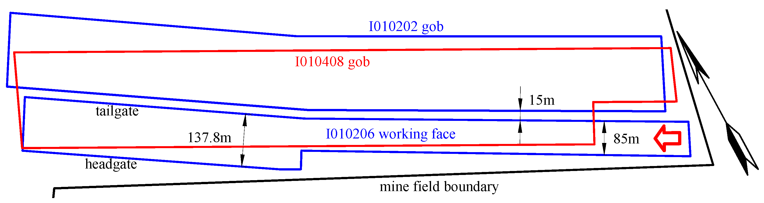
The open-off cut of the I010206 working face is 55 m away from the mine field boundary, the I010202 gob in B2 coal seam is on the north side of the I010206 working face, 15 m protective coal pillars are reserved for the I010206 working face and I010202 working face, and the upper 50 m of the I010206 working face is the I010408 working face in the B4-1 coal seam; the B1 coal seam is 25 m from the lower part of the I010206 working face. The first section of the I010206 working face is 85 m wide, the second section is 137.8 m wide, the recoverable strike length is 1672 m, the coal seam thickness is 9.5 m, the mining height is 3.2 m, the top coal caving thickness is 6.3 m. Figure 1 shows the layout of the I010206 working face, and the red is the I010408 working face in the B4-1 coal seam; blue is the I010202 gob and the I010206 working face in the B2 coal seam.
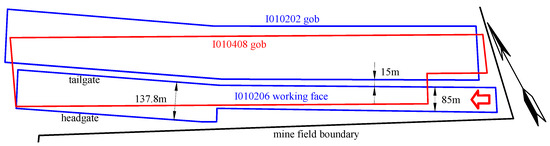
Figure 1.
Layout of I010206 working face.
3. Knife Handle-Type Working Face Overlying Rock Breaking and Inducing Mechanism
After mining, the knife handle-type working face will affect the collapse structure and form of the overlying rock strata in the stope. According to the geological characteristics of the working face, a mechanical model of the stope roof under different boundary conditions was constructed to analyze the mechanical characteristics and energy evolution rules of the roof breakage in the knife-handle type working face. Then, the overlying rock breaking mechanism of the working face roof was studied.
3.1. Stope Roof Model
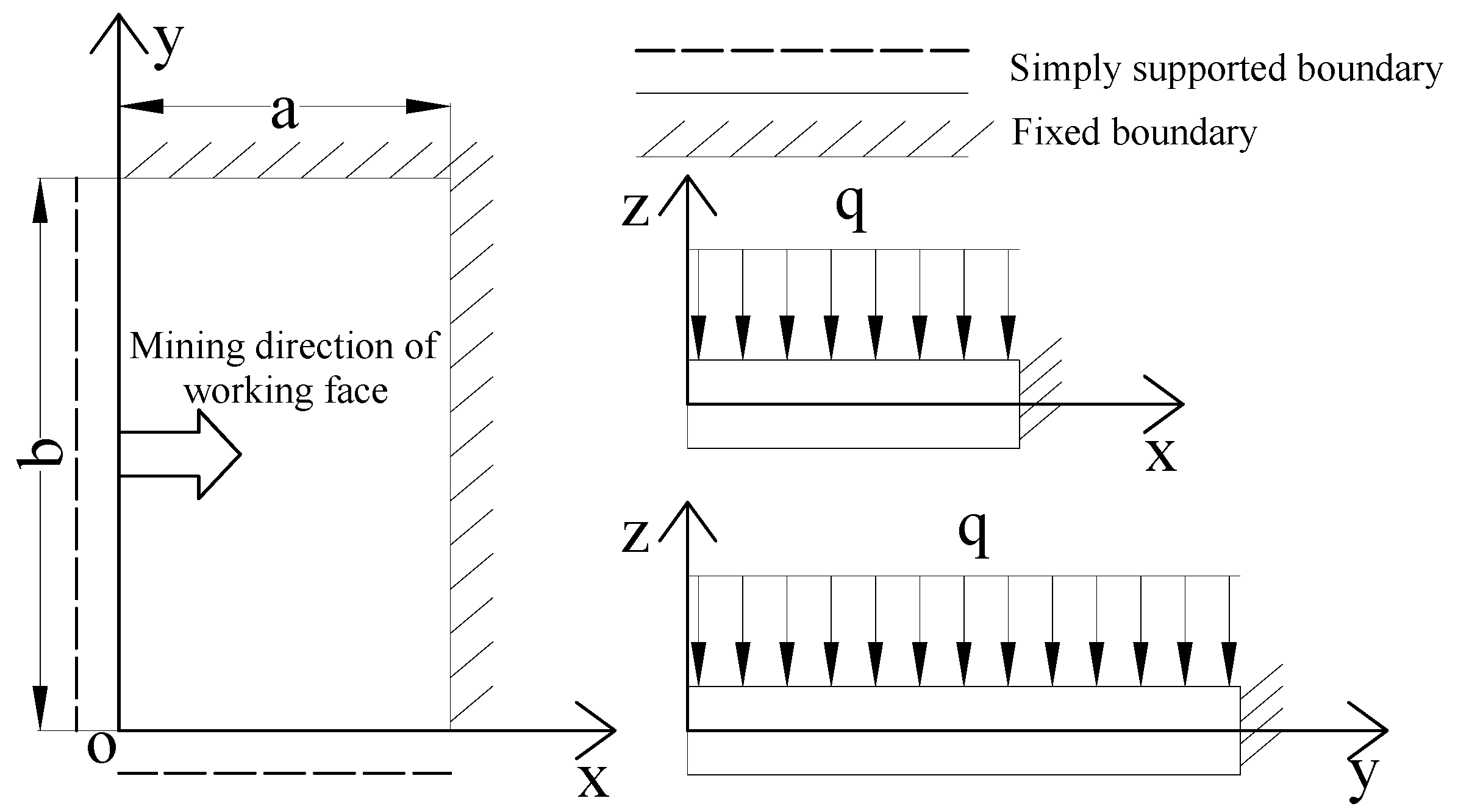
Thin plate theory is used to analyze the stability of the working surface roof [27,28], and the bending moment distribution state of the knife handle-type working surface roof is studied. Taking the I010206 working face as an example, the back of the I010206 working face is the gob; there is a 15 m protective coal pillar on the side of tailgate. The degree of plastic damage in the protected coal pillar is high, resulting in its limited support capacity for the roof, and the overlying rock of the I010202 working face has been broken; therefore, the lower side and left side of the roof are set as simply supported boundaries, and the headgate and front of the roof of the working face are solid coal areas, which are in a stable supporting state. The upper and front sides of the stope roof are set as the fixation boundaries.
According to the above roof boundary characteristics, the front of the coal wall of the working face and the tailgate trough protective coal pillar are fixedly supported boundaries, the goaf area behind the working face and the protective coal pillars of the two working faces are simply supported boundaries, and the cyclic failure mechanics model of the continuous working face is as follows: The structure is fixedly supported on both sides and simply supported on both sides. The top plate is subject to a uniform load q. The mechanical model is shown in Figure 2.

Figure 2.
Mechanical model of periodic breakage of working face roof.
Its boundary conditions are:
Assume that the deflection function is:
According to Galerkin’s law:
Calculated as:
Then, the bending moment value of the plate structure with fixed support on both sides and simple support on both sides is obtained:
The energy U(x) at any position of the short fixed support edge of the working surface roof can be obtained from the bending moment function, and its expression is:
3.2. Analysis of Roof Breakage Induction Mechanism
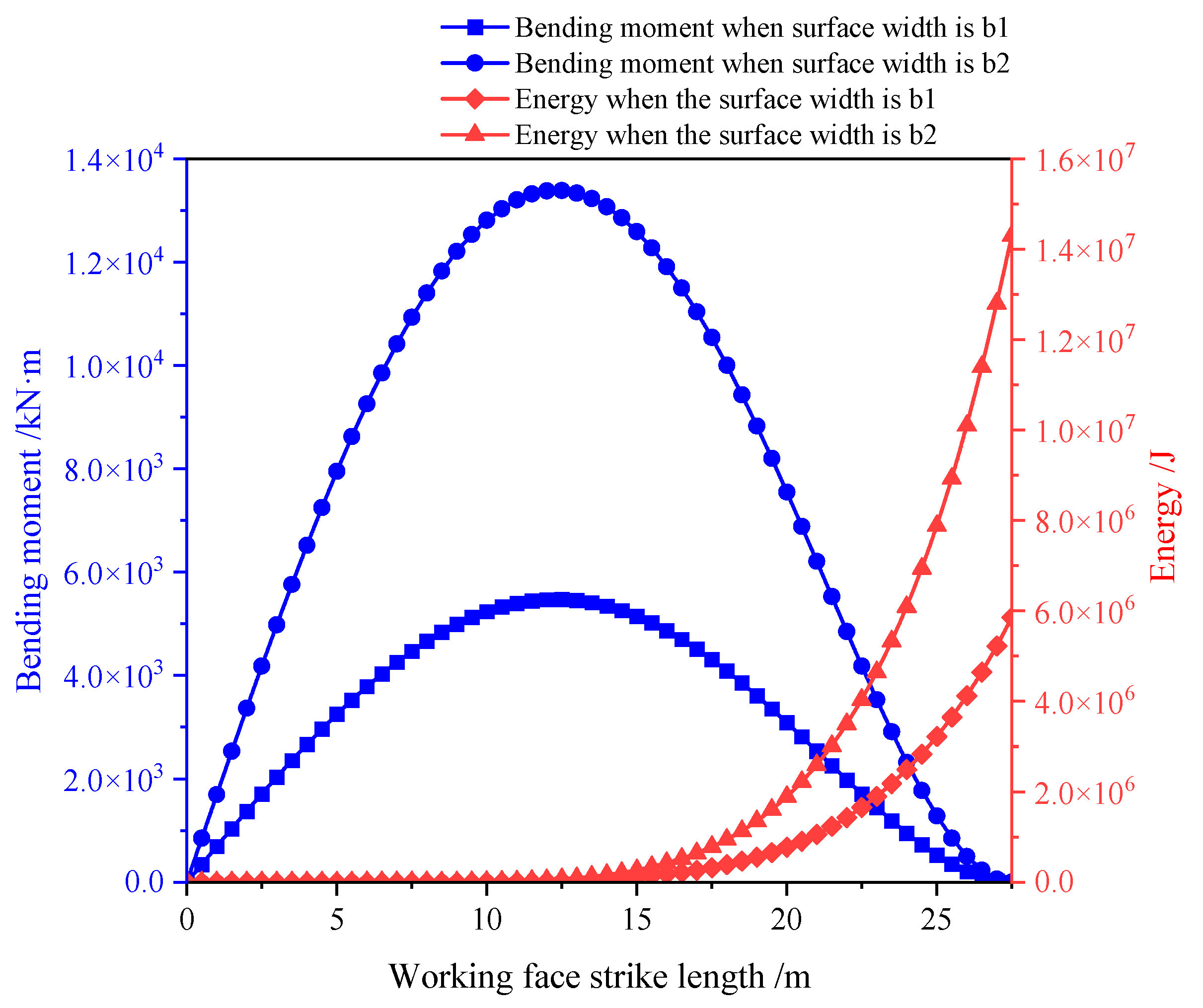
By constructing a mechanical model of the roof, the deflection expression is solved through the Galerkin method, and then the bending moment expression of the working surface roof is obtained, and through the bending moment function, the energy expression of the working surface roof is obtained. The formula of the bending moment and energy is obtained by simplifying the formula. Substituting a = 27.5 m, b1 = 85 m, and b2 = 137.8 m into Equations (9) and (10), we draw the bending moment diagram and energy diagram of the working surface roof and analyze the energy concentration law of the roof. The bending moment and energy distribution of the short fixed support edge of the working face are shown in Figure 3. The peak bending moment on the short fixed support edge is located at a position 1/√5 a away from the gob. When the working face width is 85 m and 137.8 m, the extreme bending moment values of the working face roof are 1.34 × 10⁴ kN·m and 5.47 × 10³ kN·m; the energy extreme values of the working surface roof are 1.43 × 10⁷ J and 5.85 × 10⁶ J respectively. As the width of the working face increases, the roof load further increases, and the load of the overlying rock layer is transmitted to the coal mass in front of the working face and the coal mass on the upper and lower sides of the working face. As the working face advances, the overlying rock layer reaches its ultimate strength and will fracture.
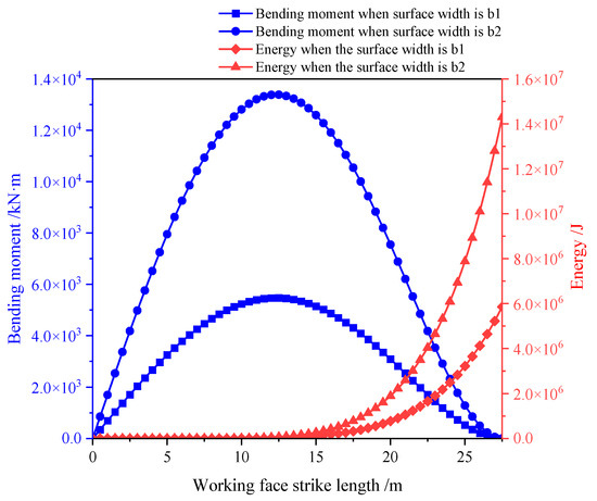
Figure 3.
Characteristics of bending moment and energy distribution of short fixed support edge of working face.
The sources of coal and rock dynamic disasters include static load stress and dynamic load stress after mining. The static load stress in the protected coal pillar area increases after mining on the working face. The dynamic load generated after mining is superimposed on the protected coal pillar area. When the coal and rock mass reaches the ultimate destructive strength, it will trigger a rock burst disaster. When the B2 coal seam is not mined, the middle rock layer of the I010408 working face of the B4-1 coal seam collapses and fills the gob. After mining the B2 coal seam, the I010206 working face forms a cantilever beam structure along the trough; as the working face continues to advance, the cantilever beam structure breaks and the beam structure rotates, causing the roof of the B2 coal seam to break. When the working face width is 85 m, the influence of mining disturbance on the working face after mining can be borne by the stable working space formed of the coal and rock mass. When the working face width increases to 137.8 m, the supporting pressure in the coal and rock mass around the stope increases, and the elastic energy accumulated in the protective coal pillar increases. When the roof of the I010206 working face was broken in the B2 coal seam, it further caused the masonry beam structure above the B4-1 coal seam to rotate at a larger angle, causing linkage instability between the B2 coal seam and the roof of the B4-1 coal seam. When overlying rock fractures induce dynamic loads, the superposition of dynamic and static loads makes it easier to induce rockburst.
4. Numerical Simulation Analysis of Knife Handle Working Face
Through the theoretical analysis in Section 3, it is concluded that when the width of the working face increases, the bending moment and energy of the fixed edge of the working face increase greatly. It is necessary to study the impact risk in the mining process of the working face by establishing a numerical simulation model, which can simulate the possibility of disasters in advance and predict the potential risks.
4.1. Materials and Methods
4.1.1. Building the Numerical Model
The FLAC3D 5.0 numerical simulation analysis software has the characteristics of continuity, which is suitable for the analysis of stress and elastic energy change characteristics in mine production and is widely used in mine mining. Through the analysis of finite element numerical simulation software, in order to fully understand the stress distribution and energy evolution characteristics of the surrounding rock in the knife handle working face, this section is based on the geological conditions of Kuangou Coal Mine and the mining layout of the working face, and builds a numerical analysis model based on the comprehensive histogram of the borehole for research.
The I010206 working face of Kuangou Coal Mine was selected as the research object. The physical and mechanical parameters of the coal and rock mass used in FLAC3D are shown in Table 1. In the process of simulation, additional parameters should be added to the simulated rock strata in the numerical model according to the parameters of each rock stratum in Table 1, so as to realize the reproduction of the field geological conditions [29,30,31,32]. The borehole comprehensive histogram is shown in Figure 4.

Table 1.
Physical and mechanical parameters of numerical simulation.
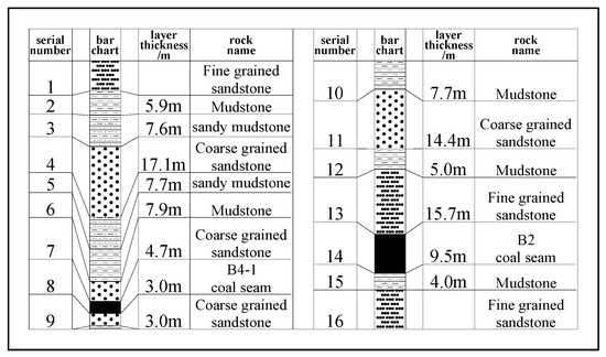
Figure 4.
Borehole comprehensive histogram.
The designed numerical model is 600 m long, 460 m wide, and 250 m high, as shown in Figure 5. The strata designed by numerical simulation are 16 layers; the coal seams are the B2 coal seam and B4-1 coal seam; the average dip angle is 14°. The simulated thickness of the B2 coal seam is 9.5 m and of the B4-1 coal seam is 3 m; the designed initial gravity acceleration is 9.8 m/s2. The Mohr–Coulomb model is adopted in the model. The initial gradient stress is applied to the top of the model. In the horizontal direction, except for the undefined boundary at the top of the model, the allowable deformation of the other five boundary surfaces is 0.2 m, and the bottom and lateral displacement of the model are limited.

Figure 5.
Numerical calculation model.
The horizontal stress applied to both sides of the model is 13.8 MPa. Since the model is not simulated to the surface, the top of the model is 310 m away from the surface. According to the Kinnick theory [33], the vertical stress applied to the top of the model is calculated as:
A vertical load of 7.75 MPa is applied to the top of the model.
4.1.2. Experimental Scheme
FLAC3D Empty elements are used to simulate the excavation of the coal seam. The specific mining plan of the model is as follows: the first step is to mine the I010408 working face in the B4-1 coal seam; the second step is to mine the I010202 working face in the B2 coal seam; the third step is to mine the I010206 working face in the B2 coal seam.
4.2. Evolution Rules of Support Pressure of Knife Handle Working Surface
After the working face is mined, the stress of the coal and rock mass is redistributed; the stress concentration is formed in front and on both sides of the working face. In order to study the advancement distance of the knife handle working face and the evolution trend of the advanced support pressure, the measurement line is arranged at the position of x = 135 and z = 111.5 in the model. During the process of the working face advancing from 200 m to 400 m, the advanced support pressure was recorded every 20 m, analyzing the distribution characteristics of the leading bearing pressure when the width of the working face changed from 85 m to 137.8 m. It can be seen from Figure 6 that the peak value of the advanced support pressure first decreases and then increases. Affected by the gob of the upper layer, the peak value of the advanced support pressure is smaller overall. When the width of the working face is 85 m, as the advancing distance of the working face increases, the peak value of the advanced bearing pressure gradually decreases from 10.75 MPa to 10.31 MPa. The change in advanced support pressure is small, and the influence range of the advanced support pressure is within 57 m in front of the working face; the peak value of the lateral support pressure dropps from 17.43 MPa to 17.23 MPa, and the change in the lateral support pressure is small. When the width of the working face is 137.8 m, the peak value of the advanced support pressure of the working face increases with the increase in the advancing distance of the working face. The peak value of the advanced support pressure increases from 10.31 MPa to 14.62 MPa. The increase in the advanced support pressure is 4.31 MPa. The stress concentration factor increased from 0.88 to 1.25, the peak value of the lateral support pressure along the crossheading on the working surface increased from 17.23 MPa to 24.67 MPa, and the lateral support pressure increased to 7.44 MPa, indicating that when the width of the working surface increases, the overlying rock migration of the roof of the working surface is severe.
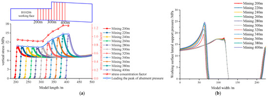
Figure 6.
Support pressure distribution characteristics during working face advancement. (a) Advanced bearing pressure distribution characteristics. (b) Lateral bearing pressure distribution characteristics.
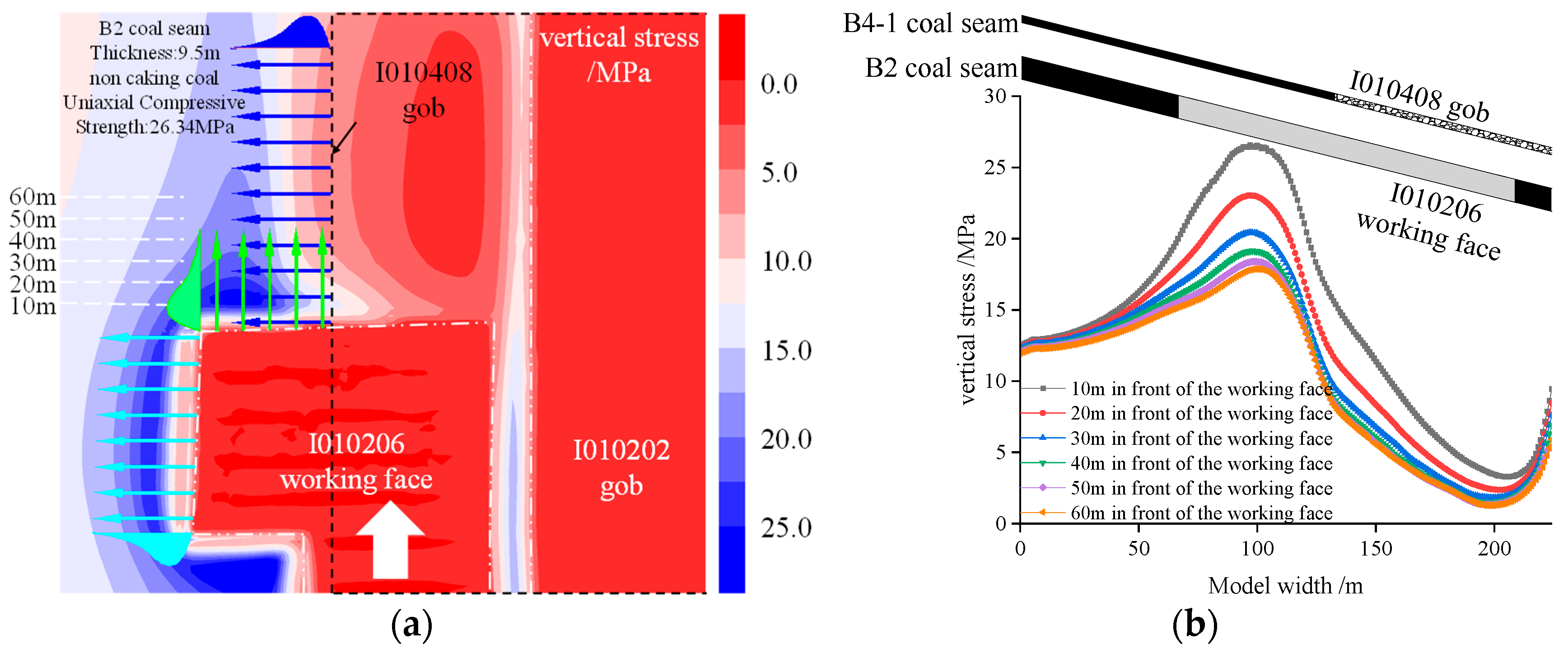
The vertical stress distribution characteristics when the working face is mined at 200 m are shown in Figure 7. After the coal seam was mined, obvious stress concentration appeared on the headgate and tailgate of the I010206 working face. Affected by the inclination angle of the coal seam, the vertical stress peak value on the headgate was greater than the tailgate. When the width of the working face is 85 m, the peak vertical stress at 10 m of the coal in front of the working face is 16.49 MPa, and the peak vertical stress at 60 m of the coal in front of the working face is 15.72 MPa. The vertical stress decrease is 5.7%. The vertical stress decreases slightly as the distance from the working surface increases.

Figure 7.
Vertical stress distribution characteristics of the working face when mining 200 m. (a) Vertical stress distribution cloud diagram of surrounding rock. (b) Vertical stress distribution characteristics of coal mass in front of the working face.
The vertical stress distribution characteristics of the working face when mining at 400 m are shown in Figure 8. As the working face advances, the geometry of the working face roof will affect the stress evolution law of the surrounding rock. When the width of the working face increases from 85 m to 137.8 m, the exposed area of the roof increases and the load transmitted by the overlying rock layer to the surrounding goaf also increases, resulting in an increase in the peak vertical stress of the coal mass in front of the working face. The peak vertical stress at 10 m of the coal in front of the working face is 26.56 MPa; the peak vertical stress at 60 m of the coal in front of the working face is 17.87 MPa. The vertical stress decrease is 32.7%. The numerical calculation results show that the extreme value of vertical stress in the large stope is higher when the working face is mined with different widths. When the working face width is 137.8 m, the artificial mining disturbance causes the stress in the coal to be readjusted, forming an advanced support pressure in the direction of the I010206 working face. The I010408 working face in the B4-1 coal seam support pressure is formed in the tilt direction, and the most severe disturbance area is the peak area of the advanced support pressure and the support pressure in the tilt direction. Therefore, rock pressure impact accidents are prone to occur near the peak superposition area.

Figure 8.
Vertical stress distribution characteristics of the working face when mining 400 m. (a) Vertical stress distribution cloud diagram of surrounding rock. (b) Vertical stress distribution characteristics of coal mass in front of the working face.
4.3. Energy Evolution Characteristics of Overlying Rock in Knife Handle Working Face
Based on the comprehensive histogram of the borehole, a FLAC3D numerical calculation model was established to study the energy distribution characteristics when the working face width changes and to analyze the energy accumulation and release rules during the mining process.
The total input energy of coal and rock mass units in the energy field generated by the stope stress environment is expressed as:
In the formula: e is the total work performed by the principal stress in the principal strain direction(J); σ1 is the maximum principal stress (MPa); σ2 is the intermediate principal stress (MPa); σ3 is the minimum principal stress (MPa); ε1 is the maximum principal stress elastic strain in the direction of stress; ε2 is the elastic strain in the direction of the intermediate principal stress; ε3 is the elastic strain in the direction of the minimum principal stress.
Hooke’s law in elastic mechanics is introduced to deduce the “stress-energy” relationship of the coal and rock mass, and the elastic strain energy expression is obtained [34] as:
In the formula, E is the elastic modulus (GPa); μ is Poisson’s ratio; Ue is the releasable elastic strain energy of the coal and rock mass (J/m3).
Using the FLAC3D numerical simulation software for secondary development, the energy distribution cloud diagram when the working face width changes is output, and the energy accumulation area during the mining process of the working face is determined. When the working surface advances every 20 m, the fish language is used to export the energy density cloud diagram, and the strain energy density of the I010206 working surface is sliced and combined, as shown in Figure 9. During the advancing process of the working surface, when the width of the working surface is 85 m, energy accumulation areas appear on both sides of the working face and the head-on side. As the working face continues to advance, the energy accumulation area further increases; the overall distribution pattern is relatively similar. When the working face width is 137.8 m, the strain energy density of the working face at different mining distances has peak values of 1.21 × 10⁵ J/m3, 1.26 × 10⁵ J/m3, 1.30 × 10⁵ J/m3, 1.38 × 10⁵ J/m3, and 1.78 × 10⁵ J/m3. As the width of the working surface increases, the peak strain energy density shows an increasing trend. As the working face continues to advance, the basic roof breaks periodically, the roof of the gob sinks further, and the strain energy density of the protected coal pillar area at the corner further increases. A large energy accumulation area of 1.78 × 10⁵ J/m3 appears in the corner protection coal pillar area, and the risk of impact increases sharply. The area here should be relieved of pressure in advance.
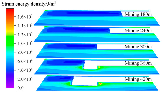
Figure 9.
Strain energy density cloud diagram at different mining distances.
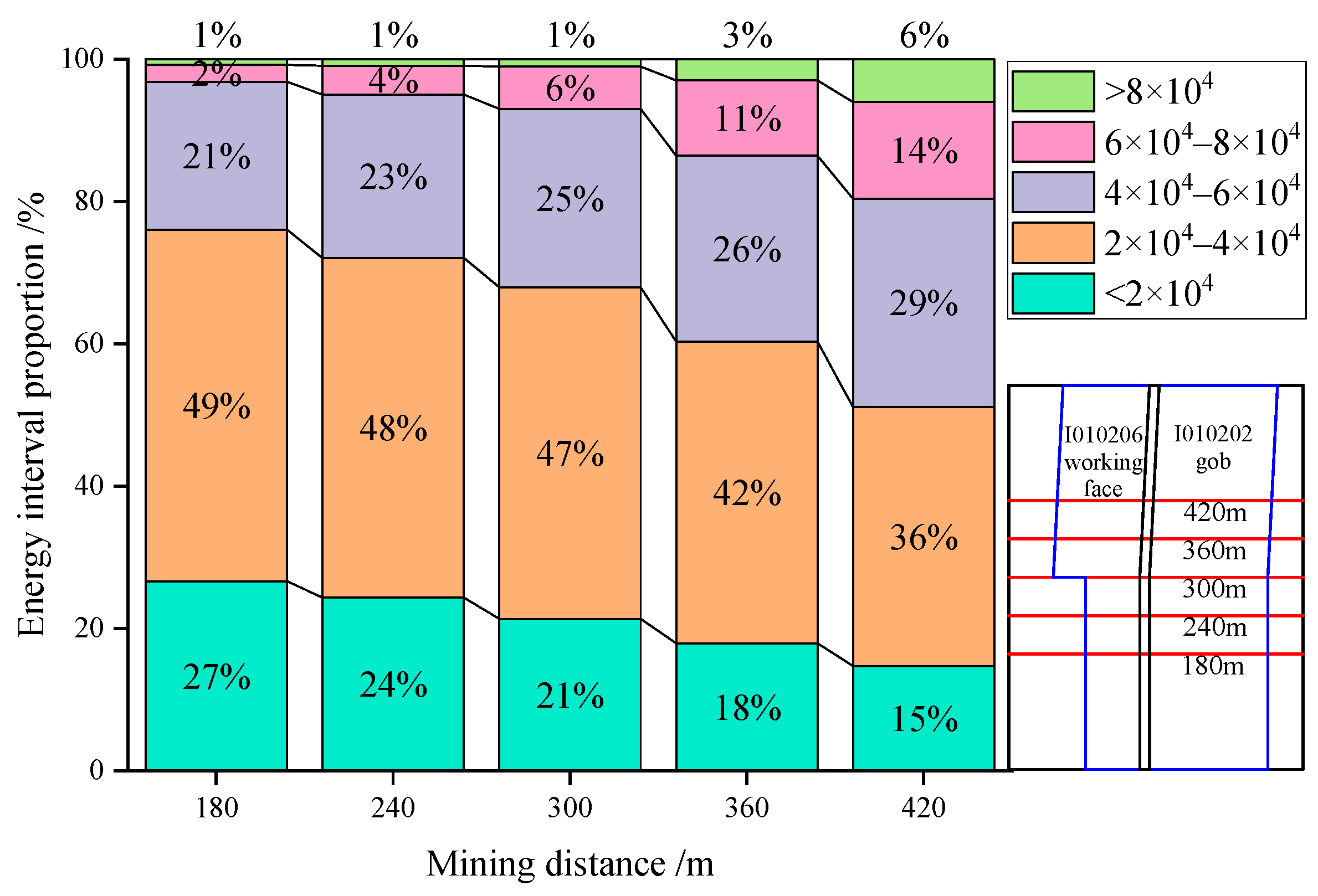
Statistics were made on the proportion of strain energy density at different energy levels during the mining process of the working face, and the proportion of strain energy density intervals at different mining distances was plotted, as shown in Figure 10. When the width of the working face is 85 m, The change range of strain energy density ratio in each interval is small, the proportion of low energy less than 4 × 10⁴ J/m3 is relatively large. When the mining width of the working face increases to 137.8 m, the proportion of high energy areas in the range of 6 × 10⁴–8 × 10⁴ J/m3 is 2%, 4%, 6%, 11%, 14%. When the working surface is advanced from 300 m to 420 m, the proportion of large energy areas in the range of 6 × 10⁴–8 × 10⁴ J/m3 increases by 57%. The proportion increased from 1% to 6%, which is in the range of 8 × 10⁴ J/m3. As the width of the working face increases, the large energy accumulation range in front of the working face and in the width changing area is wider, and the large energy area shows a gradually increasing trend as the working face advances.
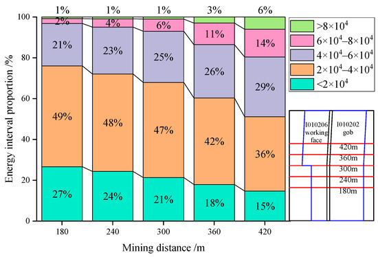
Figure 10.
The proportion of strain energy density intervals at different mining distances.
5. Measures for Preventing and Controlling Dynamic Disasters in Knife Handle Working Surfaces
The roof of the I010206 working face of Kuangou Coal Mine is a combination layer of fine-grained sandstone and coarse-grained sandstone. The average uniaxial compressive strength of the combined layer is 115.25 MPa, which is a typical hard roof. During the mining process of the working face, it is easy to form a large area of suspended roof. Through the above analysis of theoretical analysis and numerical simulation, it can be concluded that the sudden collapse of the thick hard rock layer on the roof is the main factor causing disaster. Therefore, it is necessary to implement roof-breaking measures on the thick hard rock layer on the roof to cut off the stress and energy conduction path.
5.1. Pre-Cracking Blasting Control Measures
The traditional method of dealing with hard roofs is manual blasting to force the roof pre-cracking [35,36]. When the working face width is 85 m, blasting technology is mainly used to relieve pressure on the roof. The construction plan of blasting holes for advanced presplitting of the working face is shown in Figure 11. The advanced presplitting blasting holes along the headgate are arranged in a fan-shaped arrangement, each group has four holes, the drilling diameter is 94 mm, and 80 mm charge rolls are used; the advanced pre-splitting blasting holes in the tailgate are arranged along the inclined fan shape. There are four holes in each group, the drilling diameter is 75 mm, and 60 mm explosive coils are used; there are two holes in each group of coal pillar lateral top-cut holes. The drilling diameter is 75 mm, 60 mm explosive coils are used, and each group of advanced presplit blasting holes is 5 m. Pre-splitting blasting is used to relieve pressure in advance, reduce the intensity of surrounding rock activity, and reduce the risk of impact during mining of the working face.

Figure 11.
Schematic diagram of I010206 working face presplitting blasting hole construction.
When the width of the working face increases from 85 m to 137.8 m, by analyzing the evolution law of abutment pressure and strain energy density during the mining process of the working face, it is found that when the advancing width of the working face increases, the peak lateral abutment pressure increases from 17.2 MPa to 27.2 MPa. After mining the working face at different mining distances, the peak strain energy density increases from 1.21 × 10⁵ J/m3 to 1.78 × 10⁵ J/m3, respectively. The degree of energy concentration is high. As the working face advances, the dynamic load disturbance is stronger when the hard roof collapses. It is easy to cause rock burst disasters and seriously affect the safety production of coal mines. Wen Yingyuan et al. found that the microseismic events in the gob were obviously reduced in the area where the roof deep-hole blasting had been carried out, especially microseismic events with energy greater than 103 J [37]. Cong Sen et al. indirectly reflected the release effect of coal pillar blasting on the internal stress of the working face by analyzing the variation in seismic wave velocity before and after blasting, and then evaluated the blasting effect of the coal pillar [38]. Xu Wenquan et al. used electromagnetic radiation to qualitatively test the stress distribution law of coal and rock in the working face before and after the implementation of blasting pressure relief measures, and quickly tested the blasting pressure relief effect [39]. Xie Jiahao et al. used numerical simulation to calculate the pressure relief effect of blasting. Before and after blasting, the peak stress of coal adjacent to the empty side decreased by 5.36 MPa, the maximum measured stress decreased by 5.4 MPa, and the energy and frequency of microseismic events decreased obviously [40].
However, the approval procedures for projects using blasting technology are complicated and the project volume is large. During the construction process, the release of toxic gases such as carbon monoxide is very likely to cause secondary disasters, and the working site is within the scope of mining influence, which resulted in a sharp increase in the risk of underground operations. Under the condition of frequent blasting operation, the damage of roadway surrounding rock in the mining will gradually accumulate and further deteriorate, and eventually the tunnel support system will be destroyed [41]. The treatment area of presplitting blasting measures is limited.
5.2. Hydraulic Fracturing Advanced Anti-Rockburst Technology
Because of the many drawbacks of presplitting blasting technology, combined with the actual production geological conditions of the mine, the hydraulic fracturing treatment of hard roofs is the future development direction. Hydraulic fracturing can achieve precise prevention and control the strong mine pressure dynamic disaster areas in the hard roof of Kuangou Coal Mine. The hydraulic fracturing treatment of hard roofs can reduce personnel investment, avoid associated disasters, keep the operating area away from areas affected by mining, and provide technical support for safe and efficient mine production. Therefore, hydraulic fracturing treatment can reconstruct the coal and rock structure and weaken the overall strength of coal and rock mass. This is beneficial to the control of the surrounding rock of the stope roof and the weakening and resolution of roof dynamic disasters.
5.2.1. Identification of Key Layers of Overlying Rock
In the process of coal mining, there are one or several layers of hard and thick rock layers in the overlying rock of the working face, which control the movement of all rock layers. They will affect the appearance of mine pressure and movement deformation in the stope when it breaks. Therefore, through the key layer identification formula, the key layers on the roof of the B2 coal seam are identified. The following is a derivation of the calculation formula for the load on the first layer of rock based on the principle of composite beams.
where (qn)1 is the load of the nth stratum on the first stratum; E is the elastic modulus; h is the thickness of the rock stratum; γ is the bulk density of the rock stratum.
Formula (18) is the formula for identifying the location of hard rock strata. When Formula (18) is satisfied, the calculation will no longer continue upward. At this time, starting from the first rock layer upward, the m + 1th rock layer is the first hard rock layer.
The load formed by the first rock layer is:
The first layer of fine-grained sandstone is the key layer in the mining process of the B2 coal seam, and the fine-grained sandstone is a hard rock layer with a uniaxial compressive strength of 97.8 MPa.
5.2.2. Identification of Energy Release Horizon of Overlying Strata
A large amount of energy is released after the roof of the working face breaks. By analyzing the distribution characteristics of microseismic energy during the mining process of the working face, statistics of microseismic energy release characteristics are used to locate the energy release accumulation area of the overlying rock and determine the hydraulic fracturing layer.
The microseismic events during the mining process of the I010206 working face are projected on the profile, as shown in Figure 12. The distribution height of microseismic events is within 30 m above the working face, and there are more microseismic events in the fine-grained sandstone layer, which is 15.7 m above the roof. Microseismic events above 103 J are mainly distributed within 15 m above the roof. The distribution of microseismic events indicates that the fine-grained sandstone is a concentrated energy release layer.
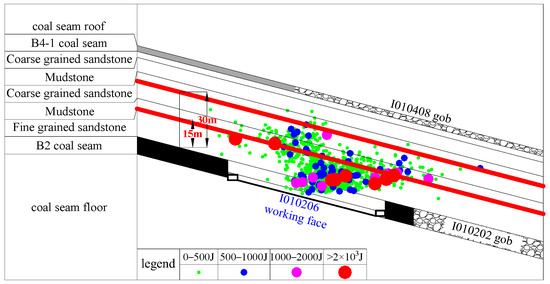
Figure 12.
Profile projection of microseismic events in I010206 working face.
Through the above identification of key layers of overlying rock and energy release layers, the fine-grained sandstone above the I010206 working face is a rock layer weakened by hydraulic fracturing, which destroys the integrity of the hard roof, weakens the intensity of energy release after roof collapse, and realizes the surrounding rock unloading weakening of pressure.
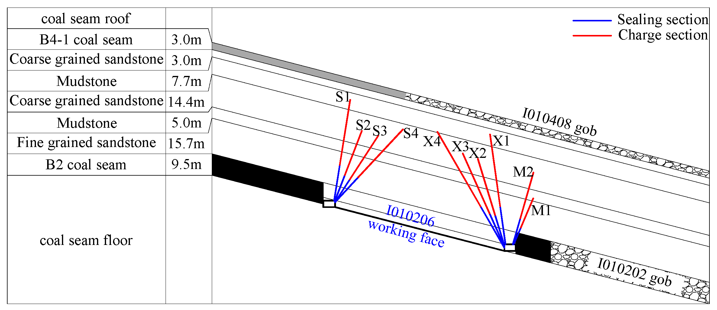
Based on the above analysis, the specific plan design for advanced hydraulic fracturing of the roadway was determined. As shown in Figure 13, the hydraulic fracturing drilling holes on the roadway roof were arranged 15 m away from the roof of the B2 coal seam.
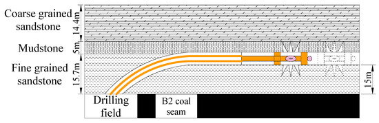
Figure 13.
Schematic diagram of hydraulic fracturing construction.
5.3. Effect Test of Pressure Relief Measures
After weakening the hard roof of the working face through hydraulic fracturing measures, on-site monitoring equipment was used to monitor the support pressure and microseismic signals during the advancement of the working face [42]; the effects of advanced presplitting blasting and hydraulic fracturing pressure relief were studied to conduct a comprehensive comparison, then guidance was provided for safe production on the working face.
The pressure characteristics of the working face during mining are shown in Figure 14. The data of the I010206 working face support were monitored. In the presplit blasting area, the average working resistance of the support was 6399 kN. When the working face is periodical weighting, and the maximum working resistance of the support during periodic pressure is 10,487 kN, the average working resistance is 7688 kN, and the average pressure step distance of the working surface is 16.0 m. After the implementation of hydraulic fracturing pressure relief, the average working resistance of the support during non-periodic pressure on the working face is 5998 kN, the maximum working resistance of the support during periodic pressure is 9513 kN, the average working resistance is 6941 kN, and the average pressure step distance on the working face is 11.4 m. Compared with the hydraulic fracturing area and the blasting area, the maximum working resistance of the support, the average working resistance, and the average pressure step distance of the working face during the period of periodic pressure decreased by 9.28%, 9.71%, and 28.75%, respectively. It shows that hydraulic fracturing construction increases the number of cracks in the roof and shortens the ultimate span of the roof, which effectively weakens the energy release after the roof break.
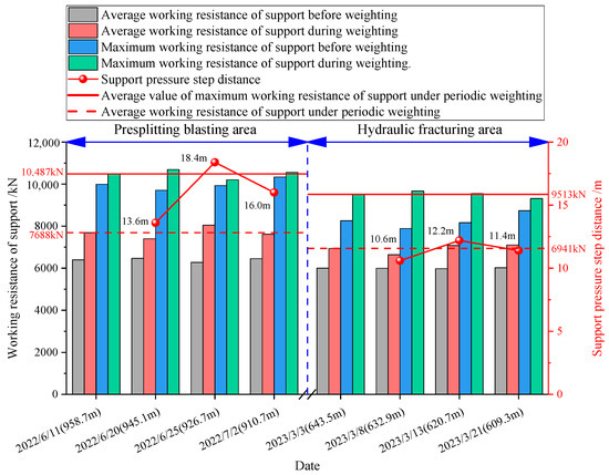
Figure 14.
Pressure characteristics during mining face.
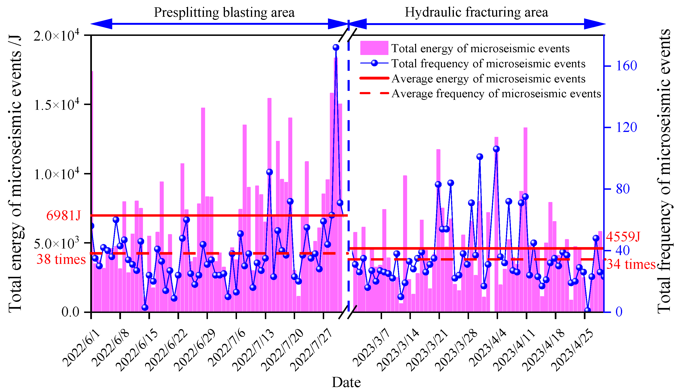
During hydraulic fracturing, cracks in the weakened area of the roof expand and create a new fracture network. As the working face advances, large-scale fractures penetrate and generate a large number of microseismic signals [30]. The microseismic energy intensity and frequency distribution characteristics during the mining process are monitored and analyzed. The effect of hydraulic fracturing is evaluated and the energy change pattern after advanced pressure relief in coal and rock mass areas is grasped. The energy frequency distribution characteristics of microseismic events are shown in Figure 15. In the presplitting blasting area, the total energy of daily microseismic events on the working face during periodic pressure is generally higher than 1 × 10⁴ J. The microseismic energy and frequency generated by overlying rock fractures during periodic pressure are generally larger. When hydraulic fracturing measures are implemented, the overall microseismic events on the working surface were controlled below 104 J, and the energy and frequency of microseismic events showed a significant downward trend. Statistics on the relationship between microseismic data and different pressure relief schemes during the mining process of the working face show that when advanced presplitting blasting is used, the total number of events with microseismic energy greater than 1000 J is 78 during mining; the average microseismic energy is 6981 J; the value of the average microseismic frequency is 38 times. After hydraulic fracturing construction, the total number of events with microseismic energy greater than 1000 J is 56 during mining. The average microseismic energy is 4559 J. The average microseismic frequency is 34 times. The number of microseismic high-energy events, the microseismic average energy, and microseismic frequency decreases were 28.2%, 34.6%, and 10.5%, respectively. This shows that the total amount of energy released from the overlying rock decreases after hydraulic fracturing, and the stress concentration of the coal and rock mass decreases.

Figure 15.
Energy/frequency comparison diagram of microseismic events.
6. Conclusions
Through theoretical analysis, numerical simulation, and field monitoring, the vertical stress and strain energy density evolution rules of the knife handle working face were analyzed, the overlying rock fracture induction mechanism of the working face was revealed, and a hydraulic fracturing layer analysis method was proposed. On-site mine pressure data and microseismic data after hydraulic fracturing were analyzed. This study leads us to the following four conclusions:
- (1)
- Based on the actual conditions of the working face, a mechanical model of the roof’s periodic fracture thin plate was established for quantitative analysis, and a mechanical model of the roof with simple support on both sides and fixed support on both sides was determined. As the width of the working face increases, the load on the roof increases and the load of overlying strata is transferred to the coal in front of the working face. The coal inclines to the upper and lower sides of the working face. The high static load is caused by the lateral support pressure of the gob and the high dynamic load is caused by the large-area collapse of the roof; they are more likely to induce rock burst.
- (2)
- Through numerical simulation, the evolution and energy release rules of the advanced support pressure are revealed in the knife handle working face. The results show that when the working surface width increases from 85 m to 137.8 m, the peak value of the advanced supporting pressure of the working surface increases from 10.31 MPa to 14.62 MPa; the increase of support pressure is 4.31MPa. The peak strain energy density of the working face increases from 1.21 × 10⁵ J/m3 to 1.78 × 10⁵ J/m3. As the width of the working face increases, the peak strain energy density shows an increasing trend, and the large energy area gradually increases when the working face advances.
- (3)
- In view of on-site impact risk factors such as higher energy concentration on the roof when the width of the working surface increases, and stronger dynamic load disturbance when the hard roof collapses, measures for advanced weakening of the hydraulic fracturing roof are proposed; the hydraulic fracturing layer is determined through the identification of key overlying rock layers and energy release layers. Support pressure and microseismic data are used to analyze the working face rockburst prevention and control plans. After using hydraulic fracturing technology, the working face roof pressure step distance was reduced, and the frequency of microseismic energy was significantly reduced, which reduced the risk of working face impact and ensured safe mining of the working face.
- (4)
- The testing of the hydraulic fracturing effect on the working face needs to be further studied and solved in actual situations. In addition to support pressure and microseismic signals, transient electromagnetic detection and borehole peeking are also often used to test the pressure relief effect. Different methods will be used in future research. Comparative analysis of fracturing effects can further improve the accuracy of monitoring results. In addition, microseismic events and acoustic emission events during the mining process can be analyzed in depth, impact risk evaluation indicators and discrimination criteria can be determined, and impact risk can be evaluated timely and accurately to ensure safe mining on the working face.
Author Contributions
F.C. conceived, designed, and analyzed the test results; J.S. performed the experiments and wrote the manuscript; X.L. use software; C.J. project administration; S.Z. participate in the processing of some data. All authors have made equal contributions to the revision of the paper. All authors have read and agreed to the published version of the manuscript.
Funding
This work was sponsored by the National Natural Science Foundation of China (No. 51874231), the Shaanxi Natural Science Fundamental Research Program Enterprise United Fund (2019JLZ-04), and the Shaanxi Province Innovation Ability Support Plan Project (2020KJXX-006).
Institutional Review Board Statement
No applicable.
Informed Consent Statement
No applicable.
Data Availability Statement
The data used to support the findings of this study are available from the corresponding author upon request.
Acknowledgments
The author sincerely thanks for the equipment and site support provided by Key Laboratory of Western Mines and Hazard Prevention of China Ministry of Education, the fund support provided by the above funding and the help of Feng Ganggui for this work.
Conflicts of Interest
The authors declare no conflict of interest.
References
- Wang, L.; Zhou, H.; Rong, T.; Ren, W. Research on the evolution rules and disturbance characteristics of stress field in deep coal mining. Chin. J. Rock Mech. Eng. 2019, 38, 2944–2954. [Google Scholar]
- Xie, H.; Zhou, H.; Xue, D.; Wang, W.; Zhang, R.; Gao, F. Research and thinking on deep coal mining and ultimate mining depth. J. China Coal Soc. 2012, 37, 535–542. [Google Scholar]
- He, M.; Xie, H.; Peng, S.; Jiang, Y. Research on rock mass mechanics in deep mining. Chin. J. Rock Mech. Eng. 2005, 24, 2803–2813. [Google Scholar]
- Pan, J.; Qi, Q.; Liu, S.; Wang, S.; Ma, W.; Kang, X. Characteristics, types and source prevention and control technology of rock bursts in deep coal mining in my country. J. China Coal Soc. 2020, 45, 111–121. [Google Scholar]
- Zhao, T.; Zhang, H.; Chen, Y.; Tan, Y. Evolution of support pressure distribution and its impact on coal and rock mass damage. J. Liaoning Tech. 2010, 29, 420–423. [Google Scholar]
- He, J.; Dou, L.; Wang, S.; Shan, C. Research on the mechanism and types of impact mine pressure induced by hard roof. J. Min. Saf. Eng. 2017, 34, 1122–1127. [Google Scholar]
- Mou, Z.; Dou, L.; Li, X.; Zhang, M. Research on the influence of roof rock layers on impact mine pressure. J. China Univ. Min. Technol. 2010, 39, 40–44. [Google Scholar]
- Cui, F.; Jia, C.; Lai, X.; Chen, J. Research on the evolution characteristics and stability of the overlying rock structure in upward mining of coal seams prone to strong impact at close range. Chin. J. Rock Mech. Eng. 2020, 39, 507–521. [Google Scholar]
- Wang, X.; Lu, M.; Gao, Y.; Luo, W.; Liu, W. Structural mechanical characteristics and instability law of roof key block breaking in gob-side roadway. Adv. Civ. Eng. 2020, 2020, 6682303. [Google Scholar] [CrossRef]
- Pu, H.; Miao, X. Influence of key layer movement in mining overburden on surrounding rock support pressure distribution. Chin. J. Rock Mech. Eng. 2002, 21, 2366–2369. [Google Scholar]
- Suchowerska, A.M.; Merifield, R.S.; Carter, J.P. Vertical stress changes in multi-seam mining under supercritical longwall panels. Int. J. Rock Mech. Min. Sci. 2013, 61, 306–320. [Google Scholar] [CrossRef]
- Dou, L.; He, J.; Cao, A.; Gong, S.; Cai, W. Principle and prevention of dynamic and static load superposition of coal mine shock pressure. J. China Coal Soc. 2015, 40, 1469–1476. [Google Scholar]
- He, J.; Dou, L.; Cao, A.; Gong, S.-Y.; Lv, J.-W. Rock burst induced by roof breakage and its prevention. J. Cent. South Univ. 2012, 19, 1086–1091. [Google Scholar] [CrossRef]
- Cao, A.; Dou, L.; Bai, X.; Liu, Y.; Yang, K.; Li, J.; Wang, C. The occurrence mechanism and management status and problems of mine earthquakes in my country’s coal mines. J. China Coal Soc. 2023, 48, 1894–1918. [Google Scholar]
- Jiang, F.; Feng, Y.; Kouame, K.R.A.; Wang, J. Research on the “creep type” impact mechanism of extra-thick coal seams under high geostress. Chin. J. Geotech. Eng. 2015, 37, 1762–1768. [Google Scholar]
- Li, N.; Wang, E.; Ge, M.; Liu, J. The fracture mechanism and acoustic emission analisis of hard roof: A physical modeling study. Arab. J. Geosci. 2015, 8, 1895–1902. [Google Scholar] [CrossRef]
- Pan, J. Research on coal mine rock burst initiation theory and its complete set of technical systems. J. China Coal Soc. 2019, 44, 173–182. [Google Scholar]
- Zhao, S. Mechanism and engineering practice of synergistic anti-collision mechanism and engineering practice of deep hole roof pre-splitting blasting. J. China Coal Soc. 2021, 46, 3419–3432. [Google Scholar]
- Chai, J. Investigation of Spontaneous Combustion Zones and Index Gas Prediction System in Goaf of “Isolated Island” Working Face. Fire 2022, 5, 67. [Google Scholar] [CrossRef]
- Bosikov, I.I.; Martyushev, N.V.; Klyuev, R.V.; Savchenko, I.A.; Kukartsev, V.V.; Kukartsev, V.A.; Tynchenko, Y.A. Modeling and Complex Analysis of the Topology Parameters of Ventilation Networks When Ensuring Fire Safety While Developing Coal and Gas Deposits. Fire 2023, 6, 95. [Google Scholar] [CrossRef]
- Zhao, X.; Huang, B.; Grasselli, G. Numerical Investigation of the Fracturing Effect Induced by Disturbing Stress of Hydrofracturing. Front. Earth Sci. 2021, 22, 2296–6463. [Google Scholar] [CrossRef]
- Grant, A.G. Fluid effect on velocity and attenuation in sandstone. J. Acoust. Soc. Am. 1994, 96, 1158–1173. [Google Scholar]
- Pan, J.; Ma, W.; Liu, S.; Gao, J. Experiment on directional pre-cracking and anti-scour technology of water jet prefabricated slots in hard roof. Chin. J. Rock Mech. Eng. 2021, 40, 1591–1602. [Google Scholar]
- Tang, S.B.; Huang, R.Q.; Wang, S.Y.; Bao, C.; Tang, C. Study of the fracture process in heterogeneous materials around boreholes filled with expansion cement. Int. J. Solids Struct. 2017, 112, 1–15. [Google Scholar] [CrossRef]
- Tang, S.; Wang, J.; Chen, P. Theoretical and numerical studies of cryogenic fracturing induced by thermal shock for reservoir stimulation. Int. J. Rock Mech. Min. Sci. 2020, 125, 104160. [Google Scholar] [CrossRef]
- Yang, J.; Chen, K.; Wang, Z.; Pang, N. Advanced weakening control technology for dynamic disasters in hard roofs. J. China Coal Soc. 2020, 45, 3371–3379. [Google Scholar]
- Yu, H. Research on the Movement of Overlying Rock Structure and Appearance of Mine Pressure in Close Coal Seam Mining. Ph.D. Thesis, China University of Mining & Technology (Beijing), Beijing, China, 2015. [Google Scholar]
- Xu, J.; Qian, M. Method for identifying the location of key overlying rock strata. J. China Univ. Min. Technol. 2000, 21–25. [Google Scholar]
- Ahmed, Z.; Wang, S.; Jasim, O.H.; Xu, Y.; Wang, P. Variability effect of strength and geometric parameters on the stability factor of failure surfaces of rock slope by numerical analysis. Arab. J. Geosci. 2020, 13, 1112. [Google Scholar] [CrossRef]
- Yin, Q.; Jing, H.; Liu, R.; Su, H.; Yu, L.; Han, G. Pore characteristics and nonlinear flow behaviors of granite exposed to high temperature. Bull. Eng. Geol. Environ. 2020, 79, 1239–1257. [Google Scholar] [CrossRef]
- Yin, Q.; Wu, J.; Zhu, C.; He, M.; Meng, Q.; Jing, H. Shear mechanical responses of sandstone exposed to high temperature under constant normal stiffness boundary conditions. Geomech. Geophys. Geo-Energ. Geo-Resour. 2021, 7, 35. [Google Scholar] [CrossRef]
- Yin, Q.; Wu, J.; Zhu, C.; Wang, Q.; Zhang, Q.; Jing, H.; Xie, J. The role of multiple heating and water cooling cycles on physical and mechanical responses of granite rocks. Geomech. Geophys. Geo-Energ. Geo-Resour. 2021, 7, 69. [Google Scholar] [CrossRef]
- Qian, M.; Shi, P. Mine Pressure and Rock Formation Control; China University of Mining and Technology Press: Xuzhou, China, 2003. [Google Scholar]
- Liu, H. Mechanics of Materials; Higher Education Press: Beijing, China, 2010. [Google Scholar]
- Banerjee, G.; Ray, A.K.; Singh, G.S.P.; Yadava, K.P. Hard roof management-a key for high productivity in longwall coal mines. J. Mines Met. Fuels 2003, 51, 238–244. [Google Scholar]
- Chhangte, S.; Pijusha, P.R. New blast ability index for hard roof management in blasting gallery method. Geotech. Geol. Eng. 2012, 30, 1357–1367. [Google Scholar]
- Wen, Y.; Guo, Z.; Cao, A.; Wang, S.; Bai, X.; Jiang, S. Analysis of pressure relief effect of roof deep-hole blasting based on microseismic data evaluation. Coal Sci. Technol. 2020, 48, 57–63. [Google Scholar]
- Cong, S.; Cheng, J.; Wang, B.; Wang, Y.; Fan, X. Evaluation method of blasting pressure relief effect based on slot wave velocity tomography. J. Coal Sci. 2018, 43, 426–433. [Google Scholar]
- Xu, W.; Wang, E.; Liu, Z.; Liu, X. Test method of blasting pressure relief effect based on borehole electromagnetic radiation method. J. Coal Sci. 2012, 37, 279–284. [Google Scholar]
- Xie, J.; Han, G.; Sun, K.; Ding, Z.; Hao, X. Anti-scour mechanism and effect test of hard roof pre-splitting blasting in adjacent roadway. J. Coal Sci. 2023, 48, 2078–2091. [Google Scholar]
- Zhu, C.; He, M.; Zhang, X.; Tao, Z.; Yin, Q.; Li, L. Nonlinear mechanical model of anchor with constant resistance and large deformation and analysis of influencing parameters of constant resistance behavior. Geotech. Mech. 2021, 42, 1911–1924. [Google Scholar]
- Cui, F.; Yang, Y.; Lai, X.; Jia, C.; Shan, P. Experimental Study on the Effect of Advancing Speed and Stoping Time on the Energy Release of Overburden in an Upward Mining Coal Working Face with a Hard Roof. Sustainability 2020, 12, 37. [Google Scholar] [CrossRef]


Disclaimer/Publisher’s Note: The statements, opinions and data contained in all publications are solely those of the individual author(s) and contributor(s) and not of MDPI and/or the editor(s). MDPI and/or the editor(s) disclaim responsibility for any injury to people or property resulting from any ideas, methods, instructions or products referred to in the content. |
© 2023 by the authors. Licensee MDPI, Basel, Switzerland. This article is an open access article distributed under the terms and conditions of the Creative Commons Attribution (CC BY) license (https://creativecommons.org/licenses/by/4.0/).