Abstract
Ambisonic room impulse responses (ARIRs) are recorded to capture the spatial acoustic characteristics of specific rooms, with widespread applications in virtual and augmented reality. While the first-order Ambisonics (FOA) microphone array is commonly employed for three-dimensional (3D) room acoustics recording due to its easy accessibility, higher spatial resolution necessitates using higher-order Ambisonics (HOA) in applications such as binaural rendering and sound field reconstruction. This paper introduces a novel approach, leveraging generative models to upmix ARIRs. The evaluation results validate the model’s effectiveness at upmixing first-order ARIRs to higher-order representations, surpassing the aliasing frequency limitations. Furthermore, the spectral errors observed in the Binaural Room Transfer Functions (BRTFs) indicate the potential benefits of using upmixed ARIRs for binaural rendering, significantly improving rendering accuracy.
1. Introduction
Ambisonics is a 3D surround-sound field format initially introduced by Gerzon et al. in the 1970s [1,2,3]. The first implementation, known as first-order Ambisonics (FOA), consists of four components, i.e., an omnidirectional component and three figure-of-eight directivity patterns, collectively referred to as the B-format [4]. While FOA captures the spatial information of the acoustical environment, its spatial resolution is limited. To overcome this limitation, higher-order Ambisonics (HOA) has been developed as an alternative approach. HOA utilizes a set of spherical harmonic (SH) expansion coefficients to accurately represent the three-dimensional (3D) sound field with greater precision [5,6]. Hence, HOA provides higher spatial resolution and a more accurate representation of spatial domain information. In applications such as binaural rendering or sound field reproduction, HOA effectively mitigated the spatial aliasing issues encountered in FOA, resulting in improved localization perception and enhanced timbre in the rendered audio [7,8,9].
In virtual reality (VR) and augmented reality (AR) applications, generating a highly realistic rendering experience often requires the utilization of measured Room Impulse Responses (RIRs). Ambisonics RIRs (ARIRs) are commonly captured and recorded using FOA microphone arrays. These arrays consist of four cardioid microphones distributed on a tetrahedron, allowing for the capture of the first-order sound field and preservation of directional information [4]. However, when capturing high-frequency content with FOA microphone arrays, the spatial resolution and accuracy of the captured sound field are reduced compared to HOA. HOA is typically measured using a multi-channel rigid or open spherical microphone array [10,11,12,13,14], such as the GFal acoustic camera, mh acoustics Eigenmike, or Brüel and Kjær spherical array. As the order of the microphone array increases, the spatial resolution improves. In other words, HOA can accurately capture the spatial acoustic response over a wider frequency range. However, an Nth-order spherical HOA microphone array requires deploying at least microphones on the surface of the sphere [10].
In practice, the FOA microphone array is a more effective solution and has been widely used for recording ARIRs. To further enhance the spatial representation capability, upmixing algorithms can be applied to extend low-order ARIRs recordings to higher-order ARIRs. Two notable methods are the Spatial Decomposition Method (SDM) [15] and the Ambisonics Spatial Decomposition Method (ASDM) [8]. These methods assume that there is a single dominant direction of arrival (DOA) within each time frame. They estimate this DOA and then re-encode the FOA signal into a HOA representation based on the estimated principal source direction. Hoffbauer et al. [16] utilized three additional directions that depend on the detected DOA to represent the diffuse sound component, increasing the echo density of the estimated signal. However, these methods assume temporal sparsity and may not effectively model complex reverberation components containing multiple overlapping DOAs. Spatial Impulse Response Rendering (SIRR) was proposed to estimate narrow-band DOA and recreate the diffuse components of the captured sound field based on a diffuseness estimate [17,18]. In summary, traditional methods for modeling ARIRs have primarily focused on synthesizing specific components, such as the direct path, early reflections, or diffuse components. These approaches typically involve first estimating the DOA of the recorded signals before synthesizing HOA signals.
A different approach focuses on upmixing by augmenting the number of microphone signals on a rigid spherical array. These additional signals are subsequently transformed into Ambisonics using a spherical harmonic transform [19]. Further, Chen et al. proposed using the Physics-Informed Neural Network (PINN) to estimate the sound field around a rigid sphere based on the measurement obtained from a set of sparsely distributed microphones mounted on the rigid sphere [20]. This method, however, focuses on modeling the sound field in the frequency domain.
In recent years, generative models, particularly generative adversarial networks (GANs) [21], have gained significant attention and success in various domains, including audio super-resolution and RIR synthesis [22,23,24,25]. The GAN framework consists of a generator and a discriminator. The generator synthesizes signals that resemble real data, while the discriminator determines the authenticity of the generated signals. These two models are trained iteratively, playing against each other. In the field of audio synthesis and speech enhancement, HiFi-GAN has emerged as an improved GAN approach [26]. In the study described in [27], HiFi-GAN was specifically employed to broaden the bandwidth of microphone measurements.
In this work, we present the first end-to-end deep learning approach for upmixing FOA RIRs directly in the time domain using HiFi-GAN. By training on raw FOA and HOA RIRs without decomposition, our model implicitly learns to preserve the complete spatial sound field. We further adopt a multi-resolution Short-Time Fourier transform (STFT) loss, enabling the generation of upmixed RIRs that retain both temporal precision and spectral accuracy. We demonstrate significant improvements in upmixing quality through extensive objective evaluation metrics.
The main structure of this paper is as follows. Section 1 discusses the limitations of FOA compared to HOA and reviews existing FOA upmixing methods. Section 3 introduces the fundamental structure of GAN networks and explains how we utilize the HiFi-GAN model for upmixing RIRs. Section 4 outlines the preprocessing steps for training data. In Section 5, we demonstrate the effectiveness of our proposed upmixing algorithm, in comparison to the baseline. Additionally, we showcase the synthesis of Binaural Room Transfer Functions (BRTFs) to highlight the potential advantages of our algorithm. Finally, Section 6 provides a summary of our proposed algorithm and the experimental results.
2. Review of Ambisonics
The incident sound pressure measured on a spherical surface, denoted as , can be expressed as an infinite-order linear combination of the spherical harmonics (SH), which are orthogonal on a sphere. The SH expansion of the incident sound pressure is as follows,
Here, represents the incident direction, where and denote the elevation and azimuth angles measured from the x-positive and z-positive axes, respectively. The wave number is defined as , where c is the speed of sound, is the angular frequency, and r is the distance from the origin. The terms are the n-order m-degree SH coefficients, which represent the Ambisonics signals. denotes the n-order m-degree SH function at . The SH functions are defined as follows,
where is the factorial function, and denotes the Legendre function.
In practical applications, the signals recorded by spherical microphone arrays can only be decomposed into a set of finite-order spherical harmonics. The finite linear combination can be represented by a matrix equation as
Here, the sound pressure is a column vector that represents the sound field measured at each discrete microphone position , . The number of microphones on the surface of the spherical array satisfies , and N is the truncated order of the SH expansion. The Ambisonic signals are put in a column vector representing the SH coefficients of the sound field. The vectors and are defined as follows,
The transfer matrix consists of N-th order SH functions. Each row represents spherical harmonics at a direction and is given by
As the transfer matrix is overdetermined, the N-th order Ambisonics can be obtained through the least squares (LS) method as
Here, is the pseudo inverse of the matrix . When , the SH basis functions consist of an omnidirectional pattern and three figure-of-eight directional patterns. In this case, the SH coefficients represent the first-order Ambisonics (FOA) signals. When , the SH coefficients represent the higher-order Ambisonics (HOA) signals.
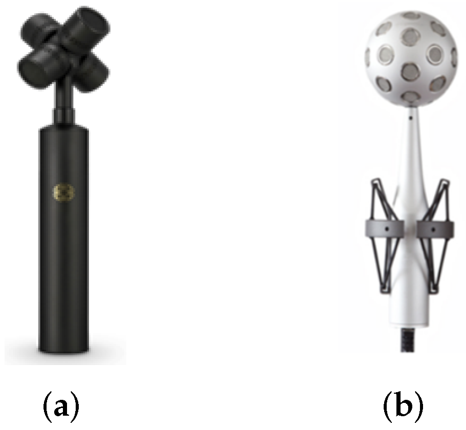
For the purpose of capturing FOA signals, the FOA microphone array (Figure 1a) serves as a widely adopted solution. This microphone array comprises four cardioid microphones meticulously arranged in a tetrahedron configuration. The signal acquired from the FOA microphone array is commonly referred to as the B-format. When it comes to capturing HOA, multi-channel spherical microphone arrays are typically employed. One popular choice for HOA recording is the Eigenmike (Figure 1b), which is a fourth-order rigid spherical microphone array. The recorded time-domain signals are processed using spherical harmonic decomposition to obtain the HOA signals.
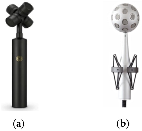
Figure 1.
The Ambisonics microphone arrays: (a) The FOA microphone array with four cardioid microphones. (b) The Eigenmike spherical microphone array with a radius of 4.2 cm and 32 omnidirectional microphones.
Considering the influence of scattering on the surface of a rigid sphere, the transformation matrix needs to incorporate the modal functions, that is
Here, the modal function for a rigid sphere is represented as
where is the spherical Bessel function of the first kind, denotes the spherical Hankel function of the second kind in the n-th order, and denotes the corresponding 1st derivative. Then, the HOA signals are calculated as follows:
where is the radial function [28].
Given the decomposed SH coefficients, we can reproduce sound pressure to a specific direction . The reconstruction process involves the Nth-order transform matrix and the SH coefficients . Mathematically, the reconstructed signal can be expressed as
Here, represents the matrix of Nth-order spherical harmonic basis functions as Equation (6).
Due to the limited number of microphones and the finite aperture of the microphone array, accurate capture of the room acoustics above the aliasing frequency is challenging. Spatial aliasing occurs when the frequency of the sound field exceeds the Nyquist frequency of the microphone array, which leads to a roll-off of high-frequency components and subsequently distorts the sound field. The aliasing frequency is determined by the condition , where N represents the SH decomposition order and r represents the array radius. For instance, the aliasing frequency of the 4th-order spherical array with a radius of cm, i.e., Eigenmike, is approximately 5.2 kHz. When the signals are recorded by the first-order spherical microphone array of the same radius, the aliasing frequency is approximately 1.2 kHz.
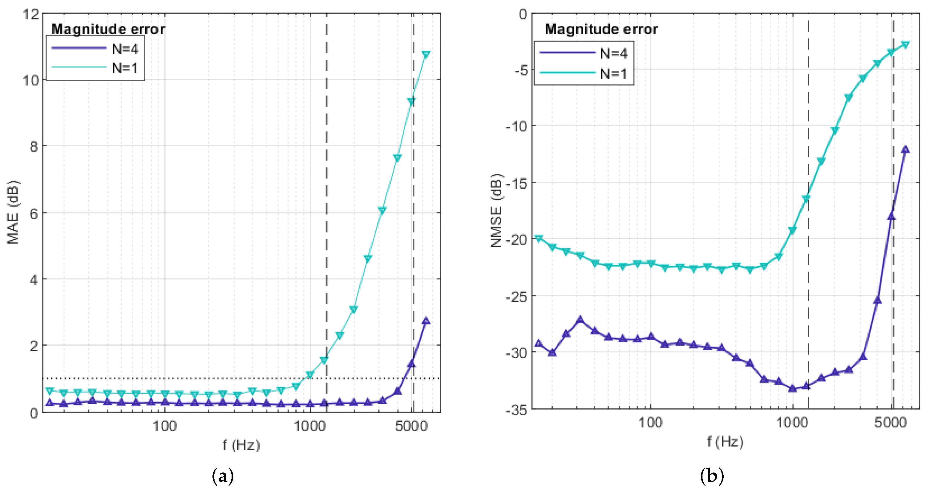
We conduct a reconstruction of the FOA and HOA RIRs measured by McKenzie et al. using an Eigenmike [29]. The reconstruction process involves mapping the ARIRs to the multi-channel signals at the positions of the microphones located on the surface of the sphere. The evaluation of the reconstruction quality is performed based on the Mean Absolute Error (MAE) and Normalized Mean Squared Error (NMSE) of the amplitude spectrum as shown in Figure 2. The MAE defined in Equation (12) is calculated as the average magnitude error between the measured sound pressure from M microphone channels on the surface of the spherical microphone array, and the corresponding estimated sound pressure at various frequency points k. The NMSE is defined in Equation (13). These metrics are averaged over reconstruction directions and one-third of octave bands:

Figure 2.
The (a) MAE and (b) NMSE of reconstructed RIRs. The green and purple lines represent the results of first-order and fourth-order reconstructions, respectively. The dashed lines in the graph represent the aliasing frequency corresponding to the first-order and fourth-order expansions, respectively. The dotted lines in (a) indicate an approximation of the just noticeable differences: 1 dB for amplitude spectrum.
It is observed that both the MAE and NMSE increase rapidly after the aliasing frequency is surpassed. The results show that the reconstruction of FOA RIRs has much lower aliasing frequencies and more significant overall errors.
3. Upmixing Ambisonics Sound Field
We use a generative adversarial network (GAN) model as the underlying network framework and employ the HiFi-GAN architecture to upmix the lower-order ARIRs to higher-order ones. In this section, we introduce the fundamental framework of the GAN model and the architecture of HiFi-GAN, which is an extended model of the GAN network.
3.1. Generative Adversarial Network (GAN)
GAN was originally proposed as an adversarial network by Goodfellow et al. [21]. The network consists of two models, a generator G that generates data close to real instances, and a discriminator D that determines whether the data are real or fake. During the training process, the two networks compete against each other by alternately training until reaching the Nash equilibrium. The objective function of the model is given by
The probability density of the real data is , and the latent variable is used as input to the generative network to generate fake data with the probability density . The discriminator network D is trained to maximize the first term in Equation (14). The generator G is trained to produce data that can deceive the discriminator such that , and minimize the second term, . The training process fixes one network and updates the parameters of the other one, alternating iterations. Eventually, the generator produces more realistic samples.
3.2. HiFi-GAN
The Ambisonics sound field upmixing approach discussed in this paper addresses the challenges posed by the low spatial resolution and limited bandwidth of FOA RIRs. To overcome these limitations, HiFi-GAN is employed to model the lower-order RIRs in the time domain, which learns a function that maps the FOA to a higher-order counterpart.
In this paper, Eigenmike is used as the acquisition device for capturing higher-order sound fields. However, it is worth noting that the proposed models can be extended to handle sound fields of an arbitrary order acquired by other types of microphone arrays. This flexibility allows for upmixing ARIRs to various orders, provided suitable training data are available. We use the first-order SH coefficients of signals recorded by Eigenmike or simulated at Eigenmike configuration as the lower-order ARIRs during the training phase. To align with the Eigenmike configuration, 32-channel signals are reconstructed from the measured or simulated FOA signals, which exclusively contain the first-order sound field information, and are utilized as inputs to the models.
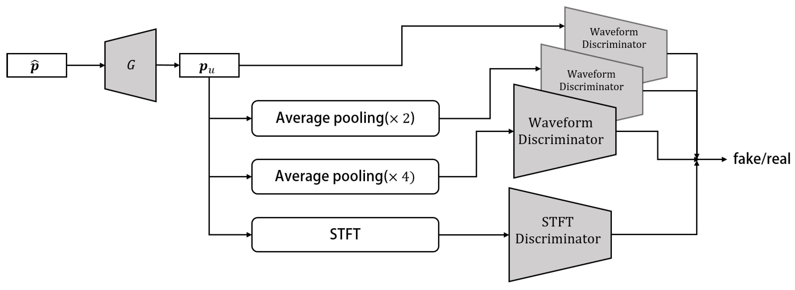
The HiFi-GAN network was initially proposed as an efficient and high-quality speech synthesis network [26,30]. Here, it is used to generate the 32-channel microphone signals, i.e., the upmixed RIRs in this work. The discriminator of this network introduces the multi-scale discriminator (MSD) and STFT discriminator to enhance the discriminative capability between synthetic and real signals. The generator module consists of an upsampling structure and employs Multi-Receptive Field Fusion (MRF). In this study, a network structure similar to that of [27] is used to model the time domain FOA RIRs. The schematic diagram of HiFi-GAN is depicted in Figure 3, illustrating the overall structure of the model. The network architecture of the generator and discriminators in HiFi-GAN is described as follows.
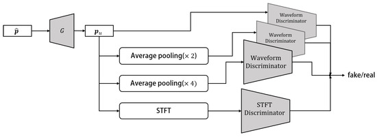
Figure 3.
The schematic diagram of HiFi-GAN includes the MSD with three Waveform Discriminators [26], as well as an STFT discriminator.
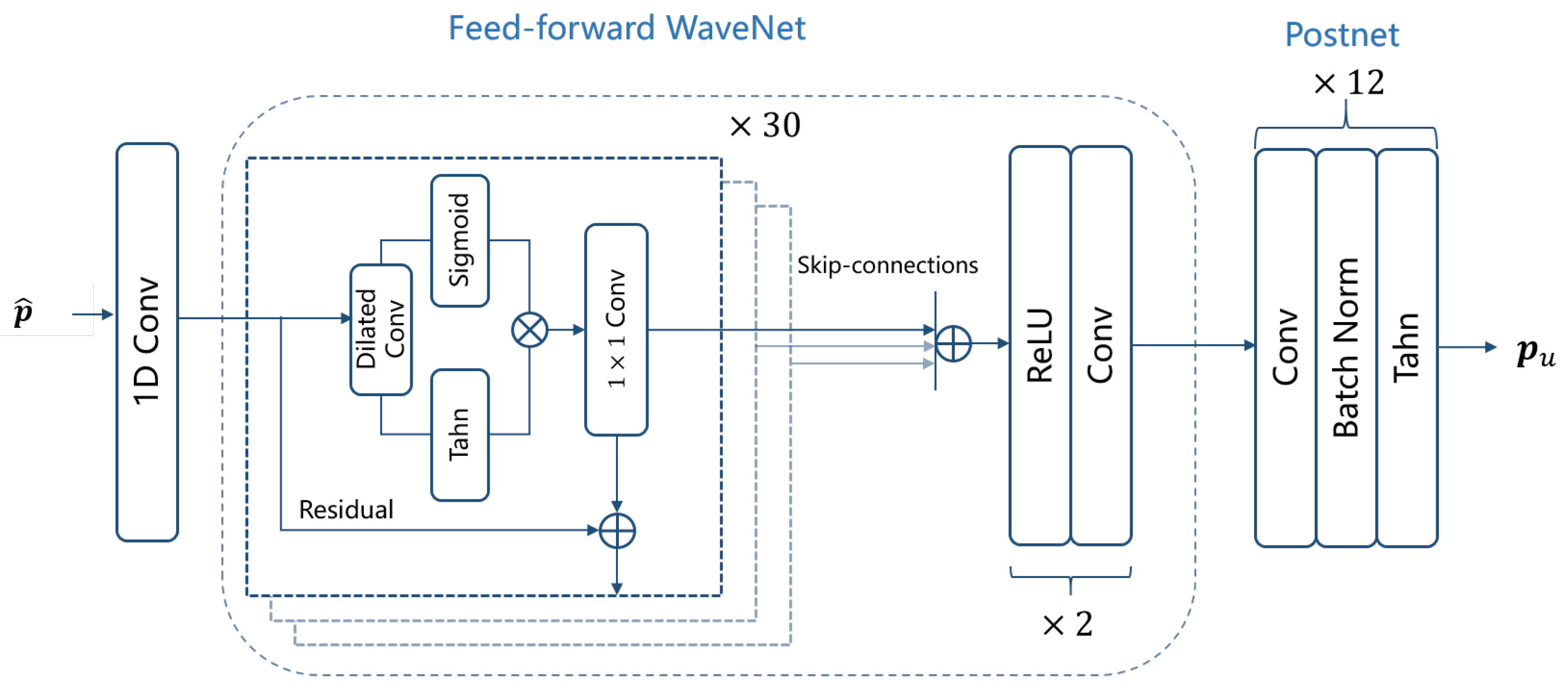
- Generator GThe generator G in the HiFi-GAN architecture consists of a 1D convolution layer, a 30-layer feed-forward WaveNet [31,32], and a postnet module [26]. The feed-forward WaveNet utilizes dilated convolutions with a kernel size of 3 and exponentially increasing dilation factors ranging from 1 to 512. This design yields a receptive field that is exponential in the number of layers. Each dilated convolution is embedded within a residual layer that includes an additional convolution and a residual connection. The contribution of the Tanh activation function in each layer is controlled by sigmoidal gates. The following postnet module consists of twelve stacks of 1D-convolutional layer and batch normalization. Each convolution layer has 128 channels and a kernel length of 32. The activation function used in the postnet is Tanh. The architecture of the generator is shown in Figure 4.
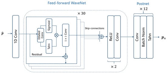 Figure 4. The Generator G architecture that is used to upmix the low-order Ambisonics signal to .
 - MSDTo effectively capture both the fine and coarse structures of the generated data, the MSD utilizes average pooling at various scales on the input signals prior to feeding them into the convolutional layers of the discriminator. The design of the MSD framework draws inspiration from the architecture proposed in [26], which incorporates three sub-discriminators operating at different scales: the original data and two scale-averaged pooling operations ( and average pooling). Each sub-discriminator consists of strided convolutional blocks, each comprising six 1D convolutional layers with Leaky ReLU activation.
- STFT DiscriminatorThe STFT discriminator is designed to capture the time–frequency characteristics of the input signals by performing an STFT on the input signal, following the approach proposed in [33]. The STFT window length is set to 2048, with a hop size set to half the window length. The network architecture of the STFT discriminator comprises four stacks of 2D convolutional layers, along with batch normalization and a Gated Linear Unit (GLU).
The loss function for the discriminators in the network model includes the loss of the generative adversarial network , the loss of the multi-scale discriminator , and the loss of the STFT discriminator . The overall loss for the discriminator is defined as
where and are weighting factors that are determined by hyperparameter search. The loss function is denoted as
The output of the D is between 0 and 1, and the training objective is to make approach 1 and approach 0.
The loss of MSD is
where represents , and and represent the measured higher-order microphone array signals and the generated signals, respectively.
The loss function of the STFT discriminator is computed as the sum of the spectral convergence and the spectral log-magnitude over R different STFT resolutions as proposed in [27]. The STFT discriminator loss is defined as
Here, denotes the F-norm, and is the STFT operator which transforms the flattened time-domain multi-channel RIRs of dimension into the spectrogram of dimension . M represents the number of RIR channels, K is the number of time samples of the impulse response, L is the number of frequency bins, and W is the number of frames in STFT. The multi-resolution loss in the STFT discriminator is computed by considering four distinct STFT resolutions: 1024, 2048, 512, and 256. The hop size is set to half of the STFT length, which allows for overlapping segments during the transformation. We used a Hann window as the window function for the STFT. The loss function of the generator in HiFi-GAN is written as
where the loss of the generative adversarial network is
During training, the generator network model is designed so that it produces signals that the four discriminators cannot distinguish from real signals. This encourages the generator to upmix the first-order ARIRs to higher orders. The Adam optimizer is employed to train the model, while the batch size is set to 8, and the training process iterates for a total of 65 epochs to yield the results.
4. Training Data
The training of the network is carried out using a combination of simulated and measured RIRs. The evaluation of the model’s performance is conducted using measured RIRs. The measured RIRs used in this study were recorded by McKenzie et al. using the Eigenmike in reverberation chambers. This dataset comprises five source positions and seven receiver positions, repeated with five different room configurations that exhibit varying levels of reverberation. In total, the dataset consists of 102 sets of RIRs [29]. The reverberation time (RT60) of the rooms ranges from 250 to 800 ms. To prepare the data for training, the database was downsampled to a sampling rate of 16 kHz. To accommodate the resource limitations of the training server, we truncated the RIRs to include only the first 4096 data points. This truncated portion corresponds to a duration of 256 ms of the RIRs. This 256 ms segment was used for modeling and analysis in our research. While this truncation reduces the length of the RIRs, our experimental results demonstrate the excellent upmixing performance of the proposed method.
We augmented our dataset by generating simulated RIRs using the SMIR toolbox [34]. The simulated dataset includes 35 different room acoustic configurations with variations in room size and wall reflection coefficients. The smallest room size in our dataset is , while the largest room size is . The reverberation time RT60 of the simulated RIRs ranges from 200 to 600 ms. In each of these room configurations, we placed the sound source at 10 different positions, allowing for variation in the source location within the room. Further more, we positioned 4 to 10 receivers within the room to capture the acoustic responses. Both the sound source and the microphones were placed on the same horizontal plane at a height of approximately 1.5 m. The RIRs were captured using a virtual rigid spherical microphone array with the same distribution as the Eigenmike, resulting in 4th-order RIRs. The simulation setup involved using a sampling rate of 16 kHz and generating RIRs with a length of 4096 samples. In total, we simulated 1450 sets of RIRs.
Both the measured and simulated microphone array RIRs were generated based on the scattered nature of the 4th-order rigid sphere. The corresponding FOA signals can be derived by substituting into Equation (10), and reconstructed using Equation (11) to align with the Eigenmike configuration. These reconstructed FOA signals, which contain only first-order sound field information, were utilized as the input signals of the model. The RIRs from both the simulated and measured databases were used as target signals for the model. The combined database used in this study consisted of 40 different room configurations, resulting in a total of 1552 sets of measured and simulated spherical array RIRs.
During the training phase, the input first-order reconstructed RIRs and target signals were reshaped from dimensions of to 16,384 × 1. The HiFi-GAN architecture, described in Section 3.2, was employed for the training process. For the dataset, we divided it into two distinct subsets, i.e., a training set and a test set. Specifically, in the case of the measured dataset, it was split with an 8:2 ratio. The simulated dataset was used exclusively as the training set. This division ensures that the model is evaluated on real-world measurements to assess its generalization and performance.
5. Experiments Results
To showcase the efficacy of the generative model in addressing the FOA upmixing problem, we conduct a comprehensive analysis of the spatial characteristics exhibited by the model’s output. Additionally, we explore the potential advantages that arise from employing such RIRs in binaural rendering applications.
We conducted an experiment to estimate RIRs at 32 positions on the surface of a spherical microphone array with a radius of 0.042 m, corresponding to the Eigenmike microphone layout. Three methods were utilized for RIR estimation:
- First-order Ambisonics (FOA) reconstruction;
- Upmixed RIRs using ASDM;
- Upmixed RIRs using HiFi-GAN.
The simulation procedure for ASDM can be referred to in the work by Zaunschirm et al. [8]. The pseudo-intensity vector is utilized for estimating the DOA of the FOA RIRs, which are further used to re-encode the RIRs for the generation of the upmixed HOA RIRs. Additionally, a spectral decay correction is applied. Further details regarding the ASDM simulation procedure are not elaborated in this study.
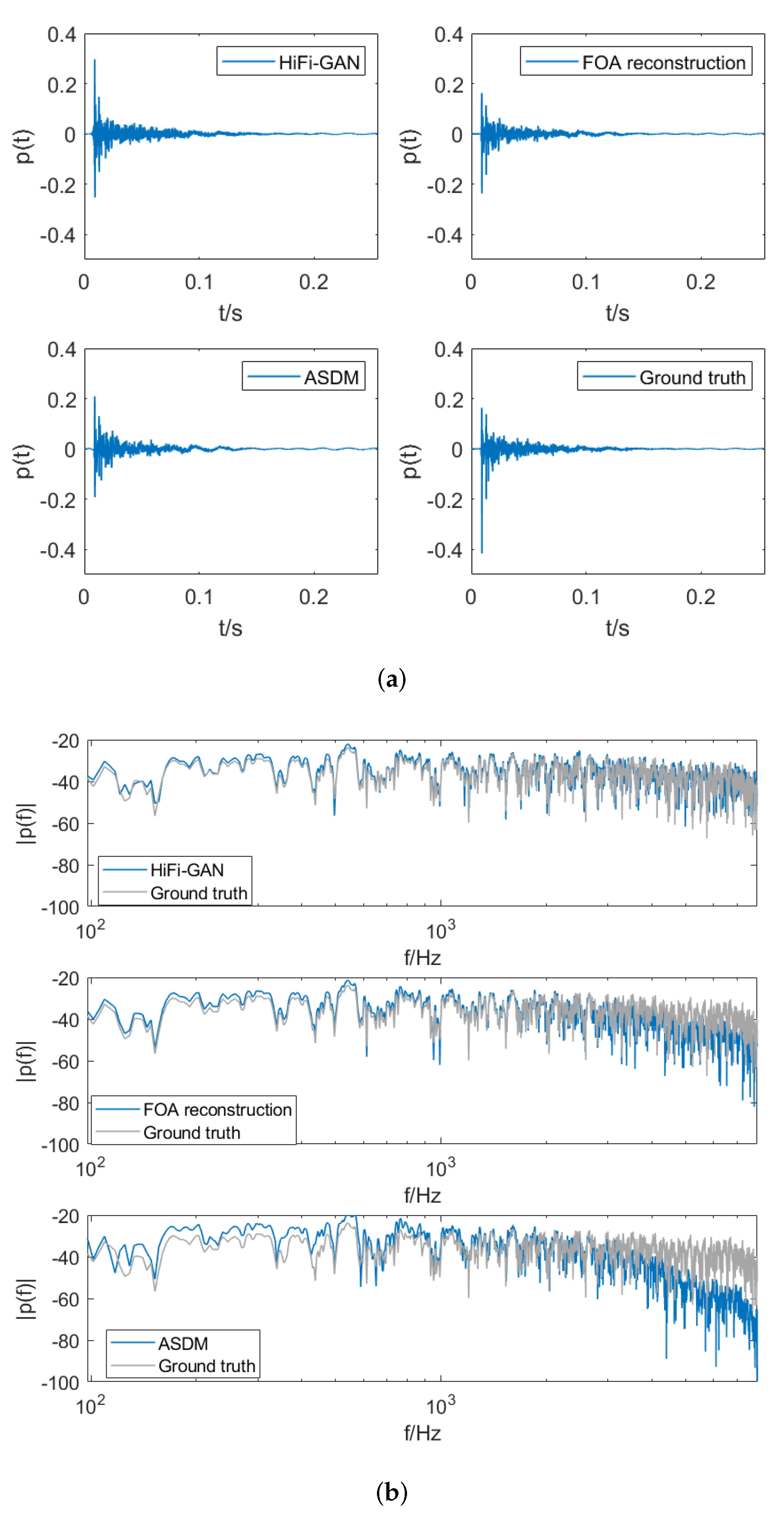
Figure 5 shows the time-domain signal and spectrum of the RIRs for the tenth channel in a test set. We can observe that HiFi-GAN effectively compensates for the high-frequency roll-off in low-order signals. Conversely, ASDM, which enhances the directionality of waves in each time window, equalizes the spectral characteristics based on the first-order signals and does not directly address the issue of high-frequency roll-off.

Figure 5.
Comparison of (a) the room impulse responses and (b) the spectrum of RIRs obtained from four scenarios: upmixed RIRs using HiFi-GAN, upmixed RIRs using ASDM, results of FOA reconstruction, and the ground truth RIRs.
To conduct a quantitative comparison of upmixing errors across different methods, the NMSE values are computed between the spectra of the three considered cases above the aliased frequency and the spectra of the ground truth. These results are averaged over the frequency range. The analysis reveals that the HiFi-GAN method exhibits the lowest error, with an average NMSE of −10.3 dB. The FOA reconstruction approach demonstrates an average estimation error of −7.9 dB. In contrast, the upmixed RIRs generated using the ASDM method exhibit a higher error of −5.3 dB.
The inferior high-frequency reconstruction in ASDM upmixed RIRs can be attributed to the lack of explicit spectral modeling during the upmixing process. ASDM upmixing relies solely on directional decompositions derived from the omnidirectional W-channel of the FOA RIRs. Consequently, the ASDM algorithm does not have a mechanism to directly optimize the high-frequency fidelity of the original FOA signals. The omnidirectional W-channel lacks adequate directional information to properly calibrate the high-frequency components during upmixing. This shortcoming results in the suboptimal high-frequency reconstruction observed in ASDM upmixed RIRs. Our proposed technique addresses this by incorporating multi-resolution spectrogram losses during HiFi-GAN training to explicitly retain high-frequency details from the original FOA RIRs.
5.1. Sound Field Reconstruction Error
In this subsection, we conduct an in-depth analysis and comparison of the spatial and frequency domain characteristics of the upmixed RIRs using the ASDM method and the proposed HiFi-GAN method, in comparison with RIRs obtained through the Ambisonic encoding of the original FOA recordings. This analysis extends to various frequency points beyond the aliasing frequency. The colorbar displayed in Figure 6 within the figure represents values in decibels (dB).
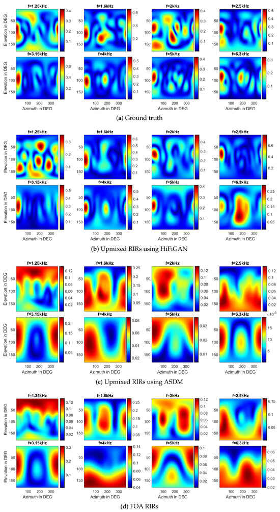
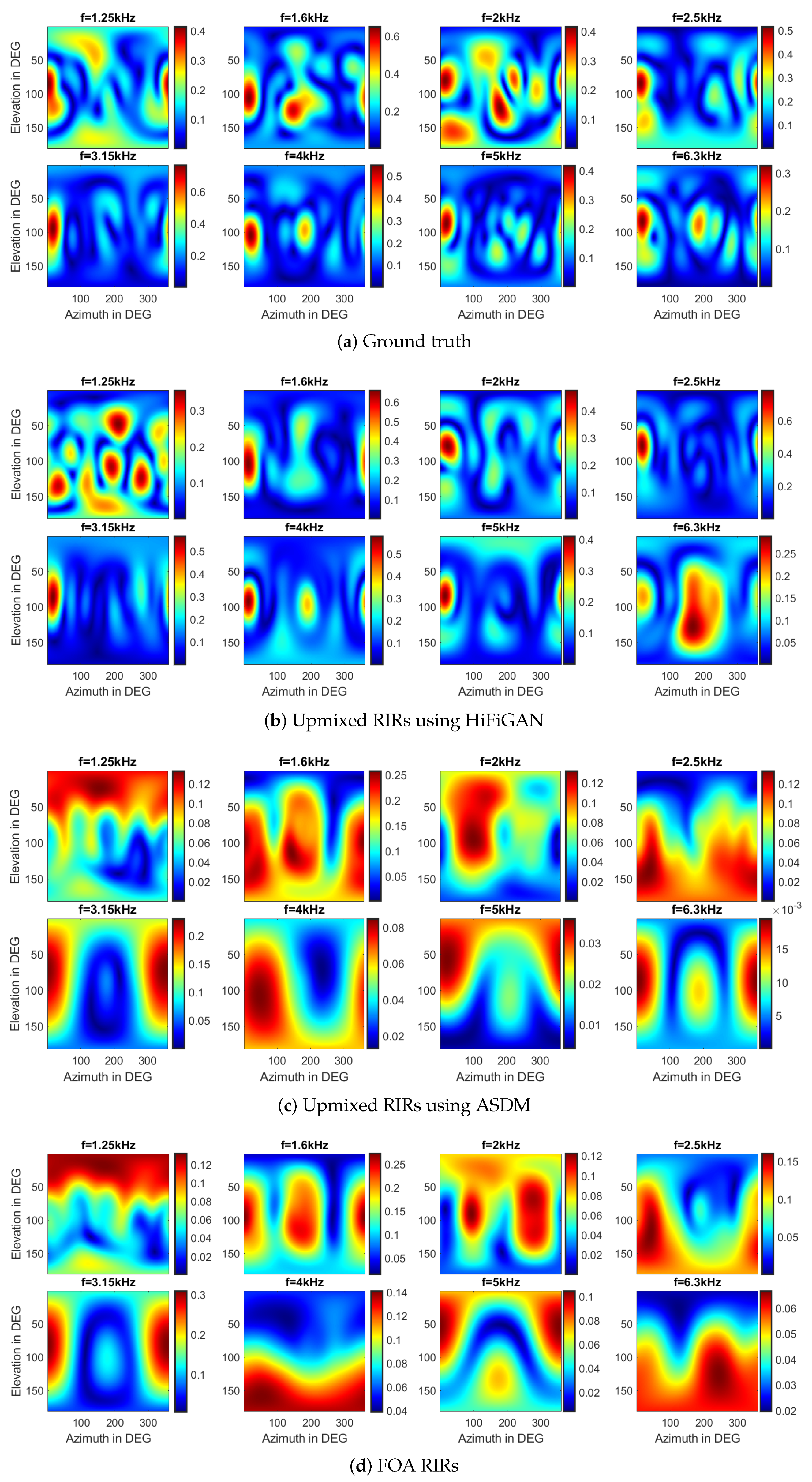
Figure 6.
The spatial responses at different frequency points above the 1st-order aliasing frequency on the sphere for the four scenarios: (a) The ground truth. (b) The upmixed RIRs using HiFi-GAN. (c) The upmixed RIRs using ASDM. (d) The results of FOA reconstruction.
Given that the spherical array RIRs contain sound field information specific to their respective locations, we first perform a visual analysis of the spatial responses at various frequency points across the sphere for four distinct signals, including the first-order RIRs, the upmixed RIRs using the HiFi-GAN model, the upmixed RIRs using the ASDM method, and the ground truth RIRs. For evaluation purposes, we specifically select the center frequency of the one-third octave band above the aliasing frequency.
In Figure 6, the spatial aliasing artifacts appear as the frequency exceeds the first-order aliasing frequency (1.2 kHz), accompanied by a noticeable roll-off in the FOA spectrum with increasing frequency. Although the upmixed RIRs using HiFi-GAN may exhibit slight variations in amplitude spectrum compared to the ground truth, they effectively preserve more accurate spatial information. It shows the effective upmixing capabilities of the HiFi-GAN model, which enhances both the spatial and spectral characteristics. Certainly, ASDM enhances the sound pressure in a specific direction, thereby sharpening the directional characteristics of the original RIRs. However, it is important to note that ASDM also is subject to certain limitations, such as DOA estimation error. Given the assumption that each time window contains waves from a single direction, the RIRs generated through the ASDM process might not fully capture the spatial and spectral intricacies of the actual, ground truth signals.
When conducting quantitative analysis to evaluate spectral errors, we exclude the ASDM method from consideration. This is due to the specific equalization process employed by ASDM, which is designed to align the spectral characteristics with the FOA signals. As a result, it has significantly larger errors when representing the high-frequency spectral components of the HOA signals.
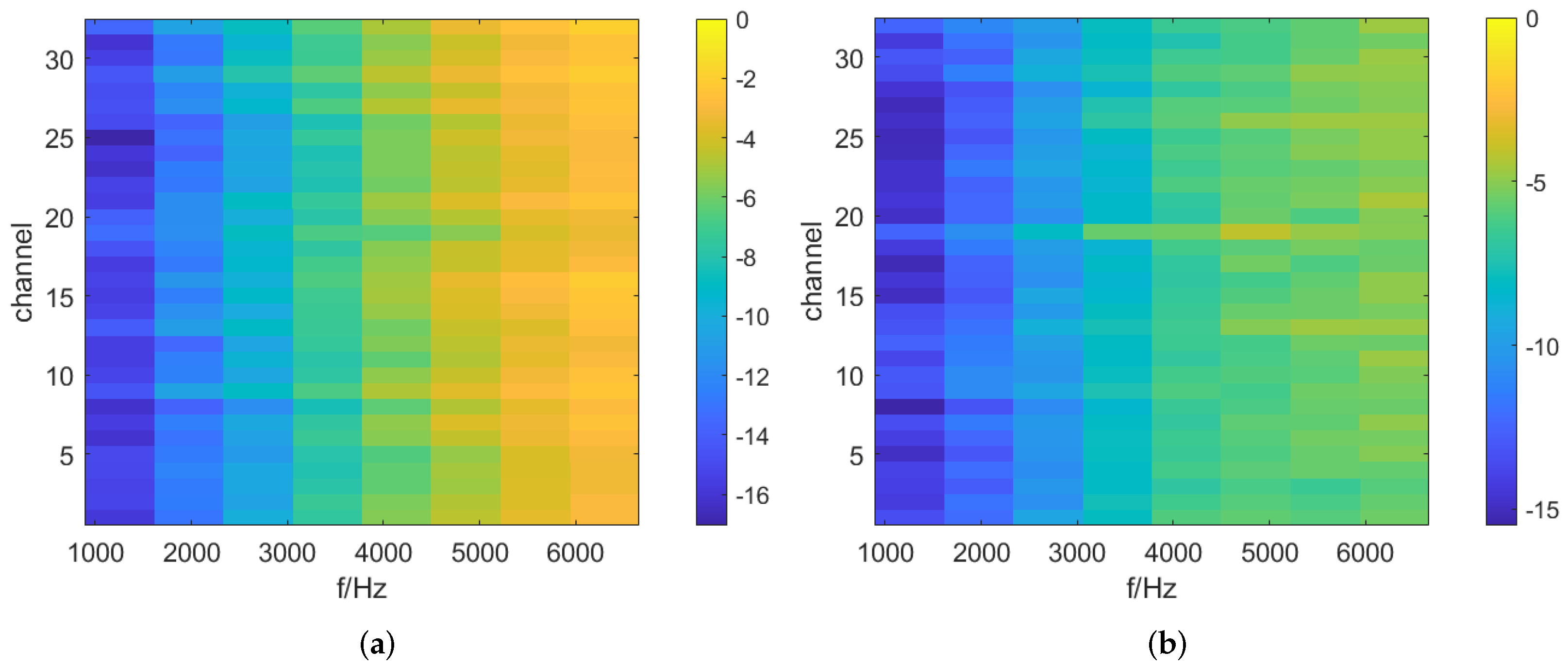
Figure 7 illustrates the NMSE values average across the 32-channel of a specific test set, which are averaged over one-third octave bands. Additionally, we calculated the NMSE separately for each channel within different test sets, and the results are presented in Figure 8. As shown in Figure 7 and Figure 8, the normalized mean square error (NMSE) values for the RIRs upmixed by HiFi-GAN are much lower compared to the original FOA RIRs for frequencies above the aliasing cutoff. Figure 7 demonstrates a maximum improvement of approximately 3.6 dB in reconstruction accuracy achieved by the HiFi-GAN model over FOA. It is worth noting that although HiFi-GAN primarily focuses on modeling the time domain rather than directly modeling the amplitude spectrum, it exhibits remarkable upmixing performance. This can likely be attributed to the multiple discriminators that perform multi-scale discrimination and STFT discrimination in both the time and frequency domains. The collective guidance provided by these discriminators facilitates the effective learning of features related to higher-order Ambisonic signals by the HiFi-GAN generator model.
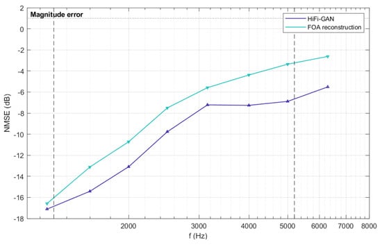
Figure 7.
The NMSE of reconstructed RIRs above the first-order aliasing frequency which is represented by a dashed line in the graph. The blue and purple lines represent the results of FOA reconstruction and upmixed RIRs using HiFi-GAN, respectively.
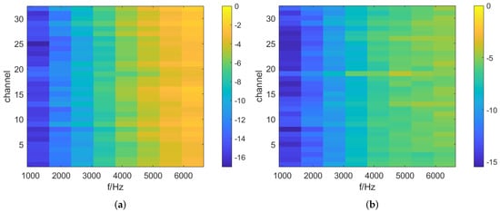
Figure 8.
The NMSE of reconstructed RIRs above the first-order aliasing frequency. (a) represents the results of the FOA reconstruction, and (b) represents the results of the HiFi-GAN output signals.
5.2. Binaural Room Transfer Functions (BRTFs) Synthesis Error
The binaural rendering technique used in this section is based on Ambisonics. This method involves convolving the spherical harmonic representation of the sound field with Head-Related Transfer Functions (HRTFs) by performing a dot product. The left and right binaural signals are then derived by summing the respective HRTF-convolved components. The synthesizing BRTF is expressed as follows,
where and represent the SH coefficients of the sound field and HRTFs, respectively. For further details on the binaural rendering algorithm, please refer to [35].
To evaluate the improvement in rendering quality achieved by using the upmixed RIRs, we compare and analyze the synthesized BRTFs obtained through the Ambisonics-based binaural rendering method under three conditions:
- The fourth-order rendering using 32-channel signals generated by HiFi-GAN;
- The fourth-order rendering using the estimated signals which are reconstructed to 32 channels by FOA;
- The first-order rendering using FOA.
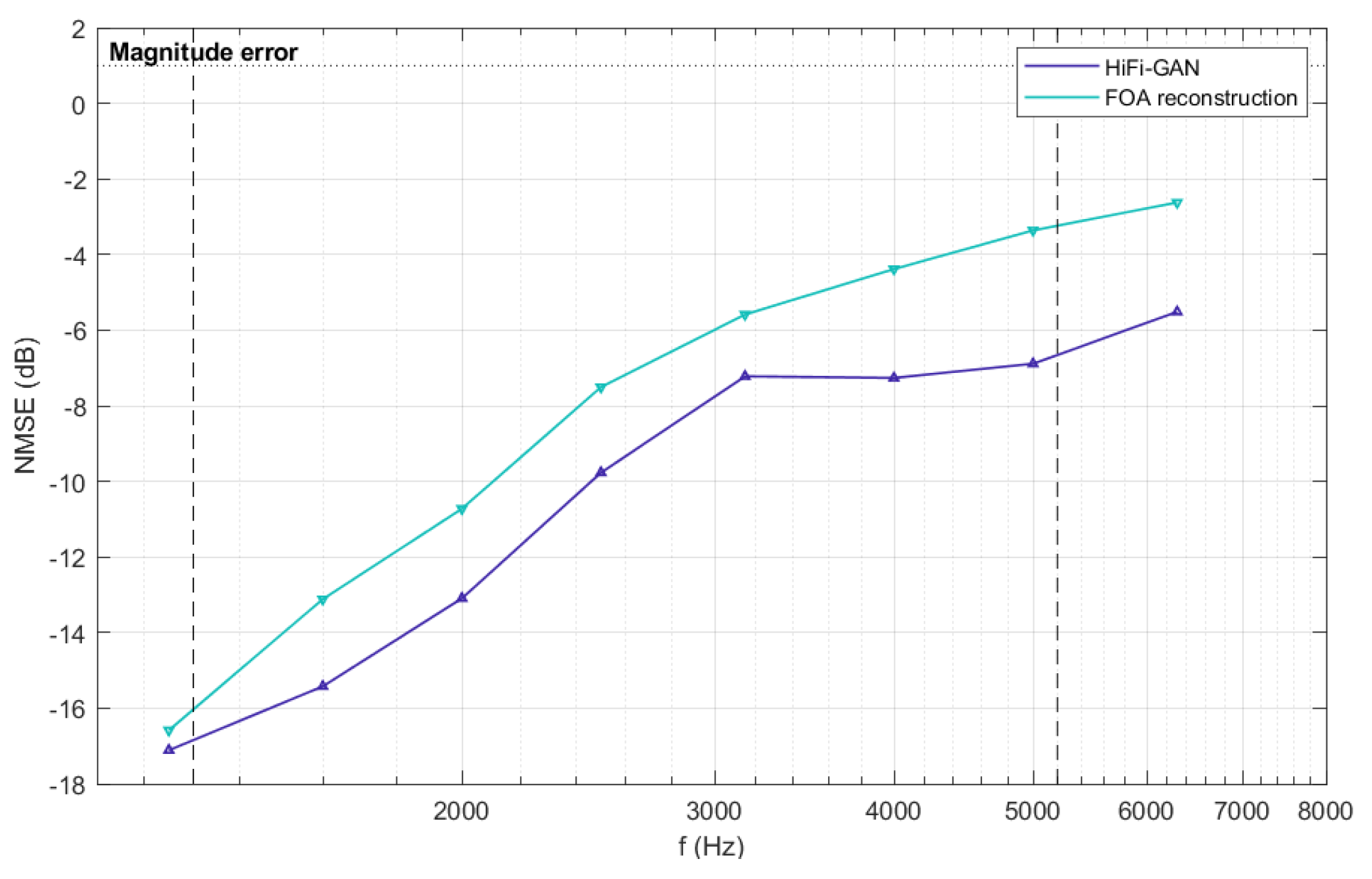
The synthesized BRTFs are evaluated using the NMSE for the amplitude spectrum above the first-order aliasing frequency. As depicted in Figure 9, HiFi-GAN exhibits significant improvement in the synthesized BRTFs, with a maximum enhancement of approximately 3.2 dB. Furthermore, the result for Condition 2 in Figure 9 indicates that when employing fourth-order HRTFs for rendering, if the sound field only contains first-order information, the improvement in the rendered results, compared to Condition 3, is only marginal. However, when upmixed RIRs are utilized, the rendering quality experiences substantial enhancement. Therefore, upmixing FOA to a higher Ambisonic order proves highly effective for achieving significant improvements in binaural rendering quality. The HiFi-GAN algorithm used in this study as the upmixing method demonstrates effectiveness in enhancing the binaural rendering quality from FOA signals.
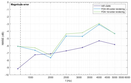
Figure 9.
The NMSE of synthesized BRTFs for three rendering conditions above the first-order aliasing frequency, which is indicated by a dashed line in the graph. The purple line corresponds to the results of fourth-order rendering using HiFi-GAN output signals in Condition 1. The green and blue lines represent the results of first-order and fourth-order rendering in Conditions 2 and 3, respectively.
6. Conclusions
This paper proposed a method for upmixing B-format Ambisonics RIRs using the generative model HiFi-GAN. Unlike previous approaches that focused only on parts of RIRs, HiFi-GAN is capable of modeling complete RIR signals. It effectively learns the temporal–frequency domain characteristics and spatial features of low-order RIRs through a set of discriminators containing multi-scale and STFT discriminators, along with a generator with multiple receptive fields. HiFi-GAN successfully upmixes first-order Ambisonic RIRs to higher orders. The upmixed RIRs exhibit higher reconstruction accuracy beyond the aliasing frequency range compared to the original B-format RIRs. This improvement in accuracy enhances the synthesis of BRTFs, allowing the upmixed RIRs to be used for high-fidelity binaural audio rendering at higher Ambisonic orders.
Author Contributions
All authors discussed the contents of the manuscript. J.X. performed the experimental work and wrote the original draft preparation; W.Z. contributed the research idea and guidance and assisted with the modification of the paper. All authors have read and agreed to the published version of the manuscript.
Funding
This work was supported in part by the National Natural Science Foundation of China (NSFC) under Grant 62271401.
Institutional Review Board Statement
Not applicable.
Informed Consent Statement
Not applicable.
Data Availability Statement
The data used in this paper was obtained from a third-party database (https://doi.org/10.5281/zenodo.6382405) or simulated using the SMIR toolbox (https://github.com/ehabets/SMIR-Generator).
Conflicts of Interest
The authors declare no conflict of interest.
References
- Gerzon, M.J. Periphony: With-Height Sound Reproduction. J. Audio Eng. Soc. 1973, 21, 2–10. [Google Scholar]
- Gerzon, M.A. Practical Periphony: The Reproduction of Full-Sphere Sound. In Audio Engineering Society Convention 65; Audio Engineering Society: New York, NY, USA, 1980. [Google Scholar]
- Zotter, F.; Frank, M. Ambisonics: A Practical 3D Audio Theory for Recording, Studio Production, Sound Reinforcement, and Virtual Reality; Springer: Berlin/Heidelberg, Germany, 2019. [Google Scholar]
- Gerzon, M.A. The Design of Precisely Coincident Microphone Arrays for Stereo and Surround Sound. In Audio Engineering Society Convention 50; Audio Engineering Society: New York, NY, USA, 1975. [Google Scholar]
- Malham, D.G.; Myatt, A. 3-D Sound Spatialization using Ambisonic Techniques. Comput. Music J. 1995, 19, 58. [Google Scholar] [CrossRef]
- Malham, D.G. Higher Order Ambisonic Systems for the Spatialisation of Sound. In Proceedings of the International Conference on Mathematics and Computing 1999, Nanjing, China, 27–30 September 1999. [Google Scholar]
- Zaunschirm, M.; Schörkhuber, C.; Höldrich, R. Binaural rendering of Ambisonic signals by head-related impulse response time alignment and a diffuseness constraint. J. Acoust. Soc. Am. 2018, 143 6, 3616. [Google Scholar] [CrossRef]
- Zaunschirm, M.; Frank, M.; Zotter, F. BRIR Synthesis Using First-Order Microphone Arrays. In Audio Engineering Society Convention 144; Audio Engineering Society: New York, NY, USA, 2018. [Google Scholar]
- Lübeck, T.; Pörschmann, C.; Arend, J. Perception of direct sound, early reflections, and reverberation in auralizations of sparsely measured binaural room impulse responses. In Audio Engineering Society Conference: 2020 AES International Conference on Audio for Virtual and Augmented Reality; Audio Engineering Society: New York, NY, USA, 2020. [Google Scholar]
- Abhayapala, T.D.; Ward, D.B. Theory and design of high order sound field microphones using spherical microphone array. In Proceedings of the 2002 IEEE International Conference on Acoustics, Speech, and Signal Processing, Orlando, FL, USA, 13–17 May 2002; Volume 2, pp. II-1949–II-1952. [Google Scholar] [CrossRef]
- Gover, B.N.; Ryan, J.G.; Stinson, M.R. Microphone array measurement system for analysis of directional and spatial variations of sound fields. J. Acoust. Soc. Am. 2002, 112, 1980–1991. [Google Scholar] [CrossRef] [PubMed]
- Meyer, J.; Elko, G. Spherical Microphone Arrays for 3D Sound Recording; Springer: Berlin/Heidelberg, Germany, 2004; pp. 67–89. [Google Scholar] [CrossRef]
- Li, Z.; Duraiswami, R. Flexible and optimal design of spherical microphone arrays for beamforming. IEEE Trans. Audio Speech Lang. Process. 2007, 15, 702–714. [Google Scholar] [CrossRef]
- Meyer, J.; Elko, G. A highly scalable spherical microphone array based on an orthonormal decomposition of the soundfield. In Proceedings of the 2002 IEEE International Conference on Acoustics, Speech, and Signal Processing, Orlando, FL, USA, 13–17 May 2002; Volume 2, pp. II-1781–II-1784. [Google Scholar] [CrossRef]
- Tervo, S.; Pätynen, J.; Kuusinen, A.; Lokki, T. Spatial Decomposition Method for Room Impulse Responses. J. Audio Eng. Soc. 2013, 61, 17–28. [Google Scholar]
- Hoffbauer, E.; Frank, M. Four-Directional Ambisonic Spatial Decomposition Method With Reduced Temporal Artifacts. J. Audio Eng. Soc. 2022, 70, 1002–1014. [Google Scholar] [CrossRef]
- Pulkki, V.; Merimaa, J.; Lokki, T. Reproduction of reverberation with spatial impulse response rendering. In Audio Engineering Society Convention 116; Audio Engineering Society: New York, NY, USA, 2004. [Google Scholar]
- Hold, C.; McCormack, L.; Pulkki, V. Parametric binaural reproduction of higher-order spatial impulse responses. In Proceedings of the 24th International Congress on Acoustics (ICA) 2022, Gyeongju, Republic of Korea, 24–28 October 2022. [Google Scholar]
- Lübeck, T.; Arend, J.M.; Pörschmann, C. Spatial Upsampling of Sparse Spherical Microphone Array Signals. IEEE/ACM Trans. Audio Speech Lang. Process. 2023, 31, 1163–1174. [Google Scholar] [CrossRef]
- Chen, X.; Ma, F.; Bastine, A.; Samarasinghe, P.; Sun, H. Sound Field Estimation around a Rigid Sphere with Physics-informed Neural Network. arXiv 2023, arXiv:2307.14013. [Google Scholar]
- Goodfellow, I.J.; Pouget-Abadie, J.; Mirza, M.; Xu, B.; Warde-Farley, D.; Ozair, S.; Courville, A.C.; Bengio, Y. Generative Adversarial Nets. In Proceedings of the NIPS 2014, Montreal, QC, Canada, 8–13 December 2014. [Google Scholar]
- Donahue, C.; McAuley, J.; Puckette, M. Adversarial Audio Synthesis. In Proceedings of the International Conference on Learning Representations 2018, Vancouver, BC, Canada, 30 April–3 May 2018. [Google Scholar]
- Ratnarajah, A.; Tang, Z.; Manocha, D. IR-GAN: Room Impulse Response Generator for Far-Field Speech Recognition. In Proceedings of the Interspeech 2021, Brno, Czechia, 30 August–3 September 2021. [Google Scholar]
- Ratnarajah, A.; Tang, Z.; Aralikatti, R.; Manocha, D. MESH2IR: Neural Acoustic Impulse Response Generator for Complex 3D Scenes. In Proceedings of the 30th ACM International Conference on Multimedia 2022, Newark, NJ, USA, 27–30 June 2022. [Google Scholar]
- Hauret, J.; Joubaud, T.; Zimpfer, V.; Bavu, E. EBEN: Extreme Bandwidth Extension Network Applied To Speech Signals Captured With Noise-Resilient Body-Conduction Microphones. In Proceedings of the ICASSP 2023—2023 IEEE International Conference on Acoustics, Speech and Signal Processing (ICASSP), Rhodes Island, Greece, 4–9 June 2023. [Google Scholar]
- Su, J.; Jin, Z.; Finkelstein, A. HiFi-GAN: High-Fidelity Denoising and Dereverberation Based on Speech Deep Features in Adversarial Networks. In Proceedings of the Interspeech 2020, Shanghi, China, 25–29 October 2020. [Google Scholar]
- Fernandez-Grande, E.; Karakonstantis, X.; Caviedes-Nozal, D.; Gerstoft, P. Generative models for sound field reconstruction. J. Acoust. Soc. Am. 2023, 153, 1179. [Google Scholar] [CrossRef] [PubMed]
- Zotter, F. A Linear-Phase Filter-Bank Approach to Process Rigid Spherical Microphone Array Recordings. In Proceedings of the IcETRAN 2018, Palic, Serbia, 11–14 June 2018. [Google Scholar]
- McKenzie, T.; McCormack, L.; Hold, C. Dataset of Spatial Room Impulse Responses in a Variable Acoustics Room for Six Degrees-of-Freedom Rendering and Analysis. arXiv 2021, arXiv:2111.11882. [Google Scholar]
- Kong, J.; Kim, J.; Bae, J. HiFi-GAN: Generative Adversarial Networks for Efficient and High Fidelity Speech Synthesis. Adv. Neural Inf. Process. Syst. 2020, 33, 17022–17033. [Google Scholar]
- Rethage, D.; Pons, J.; Serra, X. A Wavenet for Speech Denoising. In Proceedings of the 2018 IEEE International Conference on Acoustics, Speech and Signal Processing (ICASSP), Calgary, AB, Canada, 15–20 April 2018; pp. 5069–5073. [Google Scholar] [CrossRef]
- Su, J.; Finkelstein, A.; Jin, Z. Perceptually-motivated environment-specific speech enhancement. In Proceedings of the ICASSP 2019—2019 IEEE International Conference on Acoustics, Speech and Signal Processing (ICASSP), Brighton, UK, 12–17 May 2019; pp. 7015–7019. [Google Scholar]
- Kameoka, H.; Kaneko, T.; Tanaka, K.; Hojo, N. Stargan-vc: Non-parallel many-to-many voice conversion using star generative adversarial networks. In Proceedings of the 2018 IEEE Spoken Language Technology Workshop (SLT), Athens, Greece, 18–21 December 2018; pp. 266–273. [Google Scholar]
- Jarrett, D.; Habets, E.; Thomas, M.; Naylor, P. Rigid Sphere Room Impulse Response Simulation: Algorithm and Applications. J. Acoust. Soc. Am. 2012, 132, 1462–1472. [Google Scholar] [CrossRef] [PubMed]
- Ahrens, J. Binaural audio rendering in the spherical harmonic domain: A summary of the mathematics and its pitfalls. arXiv 2022, arXiv:2202.04393. [Google Scholar]
Disclaimer/Publisher’s Note: The statements, opinions and data contained in all publications are solely those of the individual author(s) and contributor(s) and not of MDPI and/or the editor(s). MDPI and/or the editor(s) disclaim responsibility for any injury to people or property resulting from any ideas, methods, instructions or products referred to in the content. |
© 2023 by the authors. Licensee MDPI, Basel, Switzerland. This article is an open access article distributed under the terms and conditions of the Creative Commons Attribution (CC BY) license (https://creativecommons.org/licenses/by/4.0/).