Abstract
In order to study the reinforcing effect of the different grouting materials applied in fissure rock engineering, ultra-fine cement slurry, cement–silicate slurry, and MARITHAN® were used to carry out grouting tests on specimens of fissure-containing rocks. With the help of a uniaxial compression acoustic emission test system, the mechanical characteristics of the grouted specimens were obtained, and the damage process of the specimens was revealed by using the acoustic emission signals. The tested results showed the following: the residual strength of the grouted specimens using the three grouting materials increased by 16.931%, 13.075%, and 39.998%, respectively; the ultra-fine cement grouting and cement–silicate grouting specimens showed damage patterns of shear-slip damage along the original rupture surface; the specimens of MARITHAN® grouting cracked from a position near the end of the specimen with no damage to the grouted body portion; the cumulative acoustic emission energy curves of the grouted specimens showed obvious stage characteristics; and the acoustic emission energy distribution characteristics of the grouted specimens differed depending on the grouting materials.
1. Introduction
There are a large number of defects, such as fracture surfaces, joints, and faults, within rock bodies, and natural cracks and pore defects contribute to the discontinuous, nonuniform, anisotropic, and inelastic characteristics of real rock material and structure [1]. The existence of these discontinuous structural surfaces as well as the extensive development of fissures seriously affect the integrality and stability of the rock body. Grouting reinforcement technology has been widely used in various fields of geotechnical engineering and can significantly improve the structure and mechanical properties of fissure-containing rock bodies. It has remarkable reinforcement effects on fissure-containing rock bodies and is one of the most effective ways to improve rock body strength and stability. In recent years, scholars have proposed a variety of test programs and conducted a series of grouting test studies.
Based on the theory of damage mechanics, Xu et al. studied the variation rules of dynamic elastic moduli and damage variables before and after the grouting of a rock body [2]. Liu et al. proposed a new method of normal cleavage to produce fractured rock specimens, and the artificial specimens exhibited good geometrical similarity with the original rock fracture [3]. Wang et al. investigated the mechanical properties of red sandstone specimens before and after reinforcement by employing static uniaxial compression and falling hammer cyclic impact loading tests [4]. Shen et al. analyzed the mechanical properties of a grouted mass by conducting uniaxial and triaxial compression tests on the grouted mass with different fracture geometries [5]. Zhang et al. carried out nuclear magnetic resonance and shear tests on grouted solidified bodies with different grouting materials and different numbers of freeze–thaw cycles, revealing the microscopic pore evolution law and shear mechanical characteristics of the grouted fractured rock body [6].
In terms of grouting material selection, Wang et al. used cement slurry and Marithan N to reinforce broken specimens and studied the mechanical properties of the grout reinforcement specimens [7]. Yan et al. prepared a new type of grouting material by using sulfo-aluminate cement as the base material, adding polyurethane and admixture, and verified its applicability through engineering applications [8]. Zhu et al. investigated the strength characteristics and damage mode of fissure specimens before and after filling with high-permeability modified epoxy resin [9]. Zhu et al. used ultra-fine cement and epoxy resin as grouting materials to reinforce cracked specimens, and analyzed the reinforcement and damage mechanisms of the grouting materials on the fractured surfaces of the specimens by employing uniaxial and triaxial loading tests combined with scanning electron microscopy [10].
Through reviewing the relevant literature, it was found that although scholars have conducted various research on the grouting theory, grouting materials, and grouting methods when evaluating the effect of grouting, more attention has been paid to the elastic modulus, compressive strength, and other mechanical properties of the specimen before and after grouting reinforcement, and there is still a lack of research on the damage and destruction of grouted specimens in the compression process. In view of this deficiency, this study utilizes ultra-fine cement slurry, cement–silicate slurry, and MARITHAN® for grouting reinforcement tests on rock-like specimens subjected to uniaxial compression rupture. With the help of a uniaxial compression acoustic emission test system, the influence of different grouting materials on the mechanical properties of grouted specimens is investigated, and the damage to grouted specimens during the uniaxial compression test is monitored and analyzed using acoustic emission signals, aiming to provide a theoretical basis for the construction of underground projects in fissured rock bodies.
2. Experimental Methods
2.1. Fracture Specimens Preparation
Considering the difficulty of sampling natural fissured rock bodies in situ and the existence of large individual differences, we decided to use prefabricated rock-like specimens with uniaxial compression to produce fissured rock body specimens after reviewing and comparatively analyzing a large number of references. The specimens obtained using this method are essentially identical in structure and can minimize experimental errors.
We selected cement, medium sand, crushed stone, and water to make rock-like specimens [11]. Cement was M 32.5 masonry cement; medium sand had a maximum grain size of 5 mm; crushed stone had a grain size of 5 mm to 15 mm; and the water was laboratory tap water. According to the mechanical properties of the fissure rock body, we calculated that the mass ratio of cement, medium sand, crushed stone, and water was 1:0.97:1.89:0.41. In order to ensure that the strength of the specimens produced is consistent, we used electronic weighing to weigh out the mass of materials required to make nine rock-like specimens at one time, mixed the materials, poured them into the mold with dimensions of 150 mm × 150 mm × 150 mm, and put them on the vibration table for vibration. After the specimens were poured for 12 h, the molds were removed and maintained under standard conditions for 28 days.
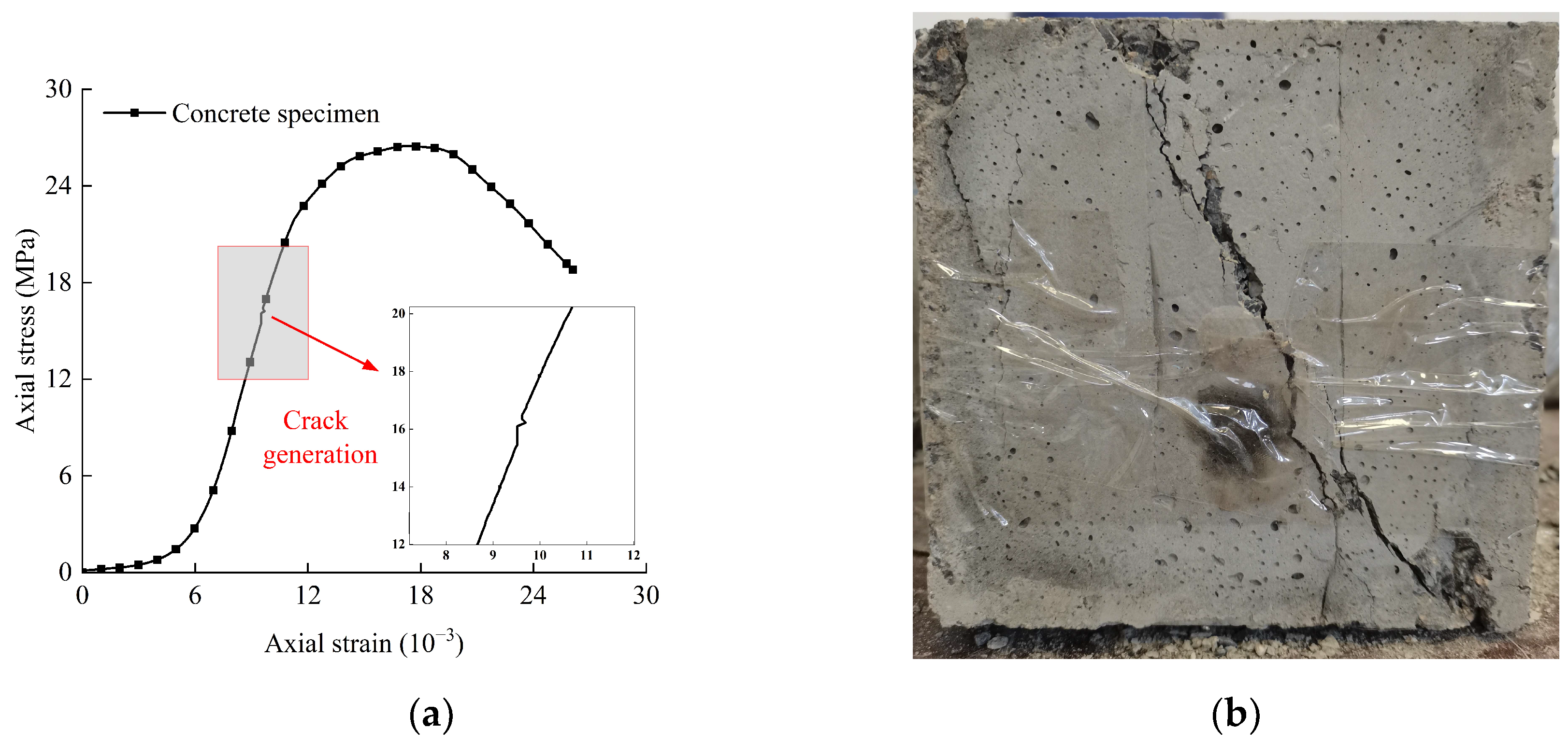
The uniaxial compression test was carried out on the cured rock-like specimens to obtain the mechanical parameters of the rock-like specimens and the fissure specimens required for grouting [12]. The stress–strain curves and damage patterns of the rock-like specimens under uniaxial compression are shown in Figure 1. From Figure 1, it can be observed that when the load reaches 60% of the peak load, the specimen produces cracks, and under continuous loading, the cracks continue to expand and develop, eventually forming the main cracks.
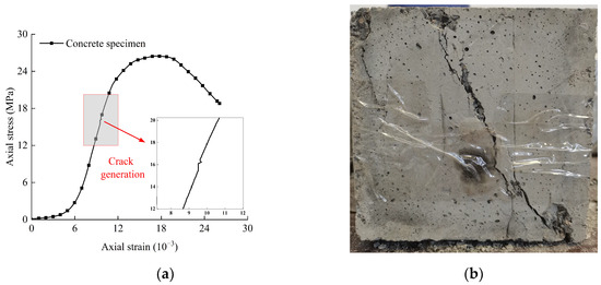
Figure 1.
Stress–strain curve and damage pattern. (a) Stress–strain curve; (b) Damage pattern.
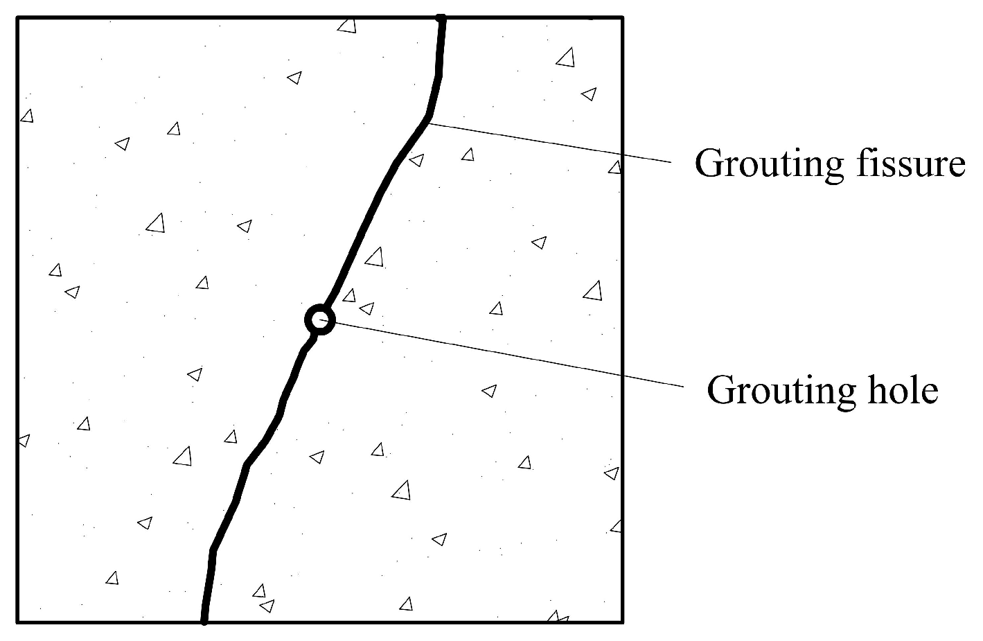
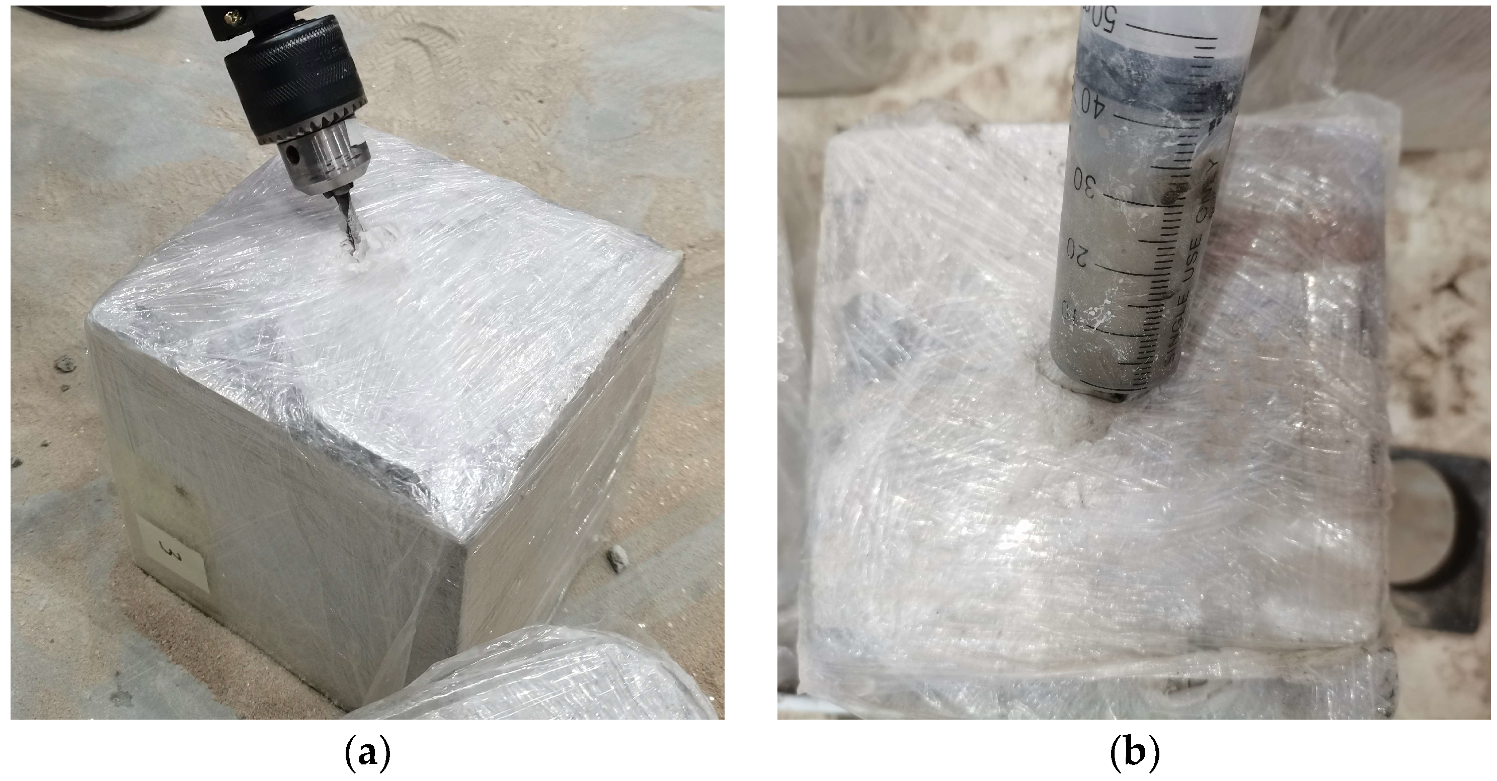
In order to replicate the field drilling and grouting test environments, a grouting hole was drilled on the side of the specimen where crack development was more obvious; the size of the grouting hole was 6 mm in diameter and 100 mm in depth, as shown in Figure 2, and the hole was cleared to meet the requirements of the subsequent grouting test [3].

Figure 2.
Schematic diagram of specimen drilling.
2.2. Grouting Materials
The grouting materials were ultra-fine cement slurry, cement–silicate slurry (C-S slurry), and MARITHAN®. The ultra-fine cement slurry employs cement with a fineness of 800 mesh and a water–cement ratio of 1:0.6. To maintain the water retention of the cement slurry in the experimental process and improve the stability of the cement slurry, bentonite was added to the slurry, which accounted for about 4% of the mass of the cement. C-S slurry uses a modulus of 2.5, Baume degrees of 40° Be′ water glass, a cement slurry water–cement ratio of 1:1, and a cement slurry and water glass volume ratio of 1:0.7. MARITHAN® consists of polyurethane (A) and curing agent (B). When grouting was performed, components A and B were mixed in a 1:1 volume ratio.
2.3. Grouting Method
In the specimen grouting hole embedded in a certain length of silicone hose as a grouting slurry flow channel, the end of the silicone hose was tightly connected to the syringe containing the grouting slurry to meet the requirements of the fissure specimen grouting. The ultra-fine cement slurry adopted the single-liquid grouting method; the C-S slurry and MARITHAN® adopted the two-liquid grouting method. The two kinds of slurries were respectively delivered through independent syringes; then, they were mixed inside the grouting holes and entered the injected fissure together. The grouting process is shown in Figure 3.
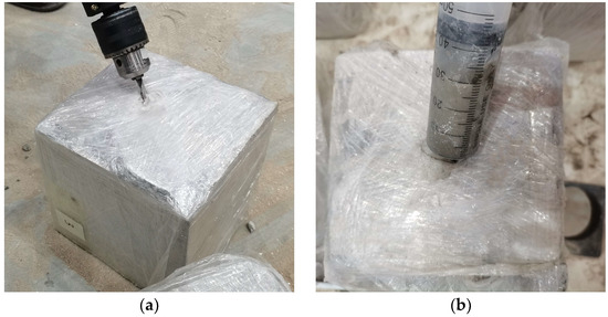
Figure 3.
Grouting process of fissure specimen. (a) Drilling the grouting hole; (b) Grouting with a syringe.
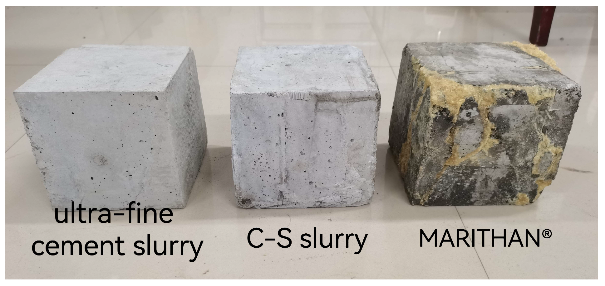
The above grouting methods were used to obtain grouting specimens with different grouting materials. The grouted specimens were placed in a room-temperature environment, and the grouting materials were allowed to cure until they reached a certain strength [7,13]. The grouting specimens are shown in Figure 4.

Figure 4.
Grouting specimens with different grouting materials.
2.4. Uniaxial Compression Acoustic Emission Test
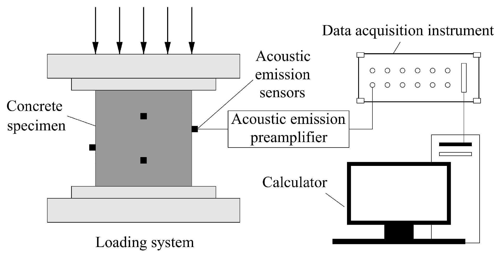
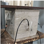
The uniaxial compression acoustic emission test system is shown in Figure 5, which was mainly composed of a stress loading system, an acoustic emission monitoring system, and a data acquisition instrument that could synchronously collect the mechanical and acoustic emission data of specimens during the loading process. In order to ensure the consistency of the acoustic emission and mechanical experiments, the acoustic emission monitoring system was turned on at the same time as the uniaxial compression test was started to collect the acoustic emission signals synchronously.

Figure 5.
Schematic diagram of the test system.
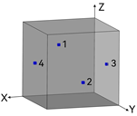
The loading system utilizes an RMT-150B rock mechanics testing machine with a maximum axial load capacity of 1000 kN. In the pre-experiment, we debugged the loading rate several times with the nature of the specimen and found that controlling the displacement loading rate at 0.02 mm/s can control the whole loading process in a suitable time range, and the acoustic emission system can clearly capture the acoustic emission signal, so we adopted this loading rate throughout the experimental process. The monitoring system utilizes a DS5 series acoustic emission analyzer, 4 channels for data acquisition, a sampling rate of 2.5 MHz, and a threshold value of 40 dB [14], which was found to be able to shield the external noise in the experimental process, combined with the nature of the specimens and experimental environment conditions. The spatial coordinates of the sensor arrangement are shown in Table 1.

Table 1.
Spatial coordinates of sensor arrangement.
3. Test Results and Analysis
3.1. Strength Comparison of Grouted Reinforcement
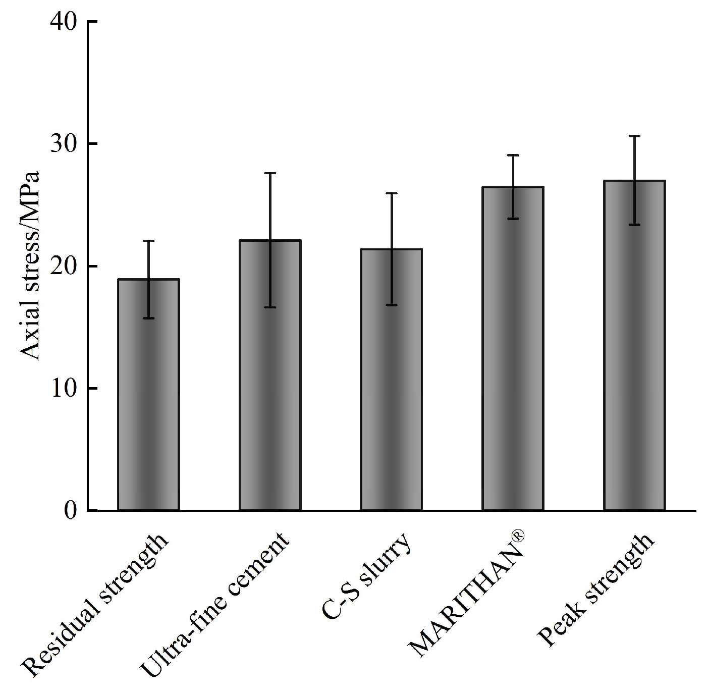
The results of the uniaxial compressive strength tests of the intact specimens before and after grouting are listed in Table 2 and Table 3, respectively, and the errors and histograms are analyzed in Figure 6.
Table 2.
Uniaxial compressive strength test results of intact specimens.
Table 3.
Uniaxial compressive strength test results of grouted specimens.

Figure 6.
Comparison of grouting effects.
Uniaxial loading is biased toward testing the bonding properties between the rock mass and the slurry [10]. Compared with the residual strength of the intact specimens, the residual strength of the ultra-fine cement grouting specimen increased by 16.931%, the residual strength of the C-S grouting specimen increased by 13.075%, and the residual strength of the MARITHAN® grouting specimen increased by 39.998%. The results show that compared with ultra-fine cement slurry and C-S slurry, MARITHAN® has better permeability and can better penetrate into the specimen and fill up many tiny cracks and fissures inside the specimen, thus better bonding the cracks and fissures.
As can be seen from Figure 6, the grouting reinforcement methods can improve the residual strength of the specimens to a certain extent, but compared to the intact specimens, the peak strengths of the three types of grouted specimens are still reduced, and their peak strength enhancement coefficients are negative, indicating that there is a limit to the increase in strength depending on the grouting method.
3.2. Analysis of Damage Patterns
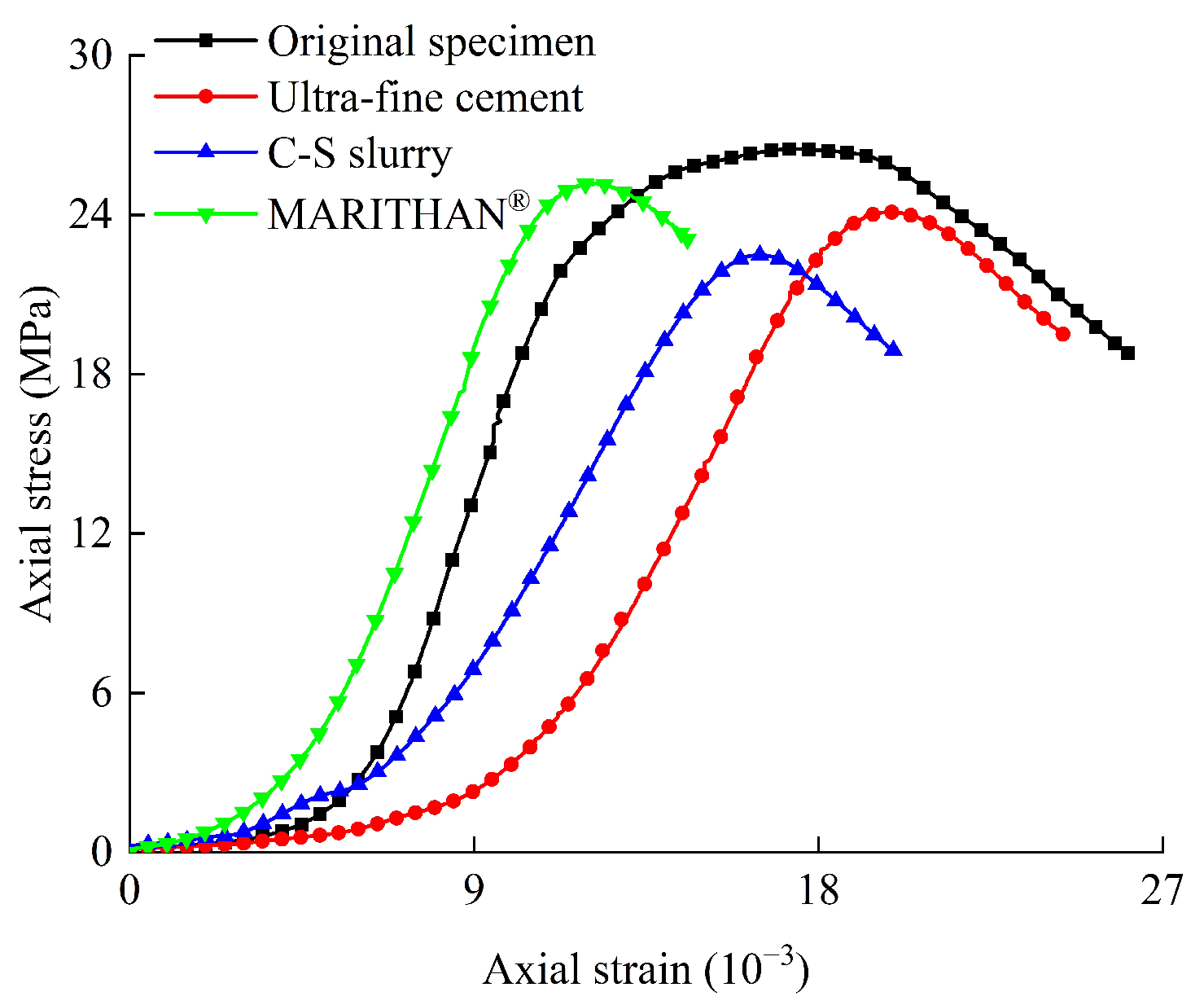
The stress–strain curves of the intact specimen, ultra-fine cement grouting specimen, C-S grouting specimen, and MARITHAN® grouting specimen are shown in Figure 7. It can be seen that the stress–strain curves of the specimens after grouting reinforcement are similar to the curves before grouting, and they all experience a peak from the elastic phase to the destructive phase. The intact specimen shows ductile damage characteristics during uniaxial loading, and the stress–strain curves do not show obvious peaks; the grouted specimens show brittle damage characteristics during uniaxial loading, and the stress–strain curves decrease more rapidly when reaching their peak strength.

Figure 7.
Stress–strain curves of specimens under uniaxial compressive load.
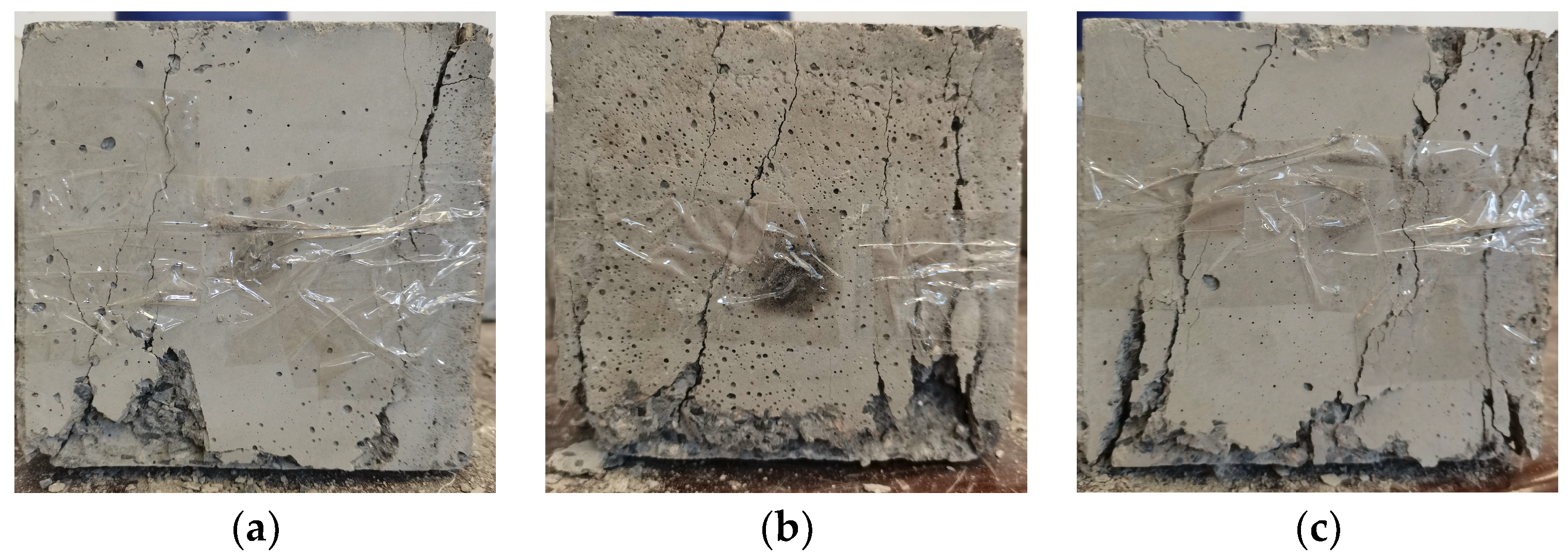
To investigate the cause, the damage characteristics of the specimens after uniaxial compression were observed, as shown in Figure 8, Figure 9 and Figure 10. The damage pattern of the ultra-fine cement grouting specimen shows shear-slip damage along the original rupture surface, and the specimen has a few secondary cracks. The damage pattern of the C-S grouting specimen shows larger shear-slip damage along the original rupture surface, and part of the grouting specimen is crushed and peeled off, indicating the lower shear and tensile strengths of the fissure bonding weak surface of the grouting specimen. For the MARITHAN® grouting specimen, the whole loading process is basically the same as the intact specimen, and there is no obvious cracking during the loading process; when the load reaches its peak, the specimen cracks from a position near the end of the specimen without damage to the grouted body portion.
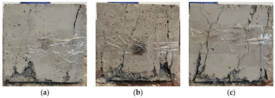
Figure 8.
Damage pattern of intact specimens. (a) Before injection of ultra-fine cement slurry; (b) Before injection of C-S slurry; (c) Before injection of MARITHAN®.
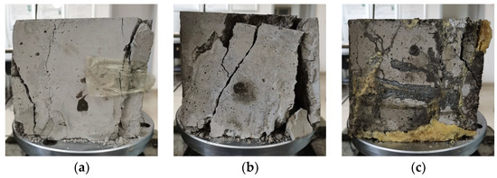
Figure 9.
Damage pattern of grouting specimens. (a) After injection of ultra-fine cement slurry; (b) After injection of C-S slurry; (c) After injection of MARITHAN®.
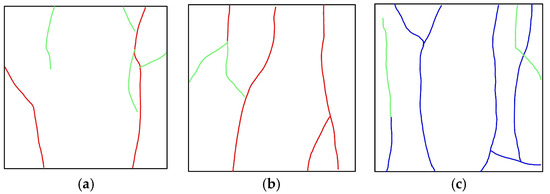
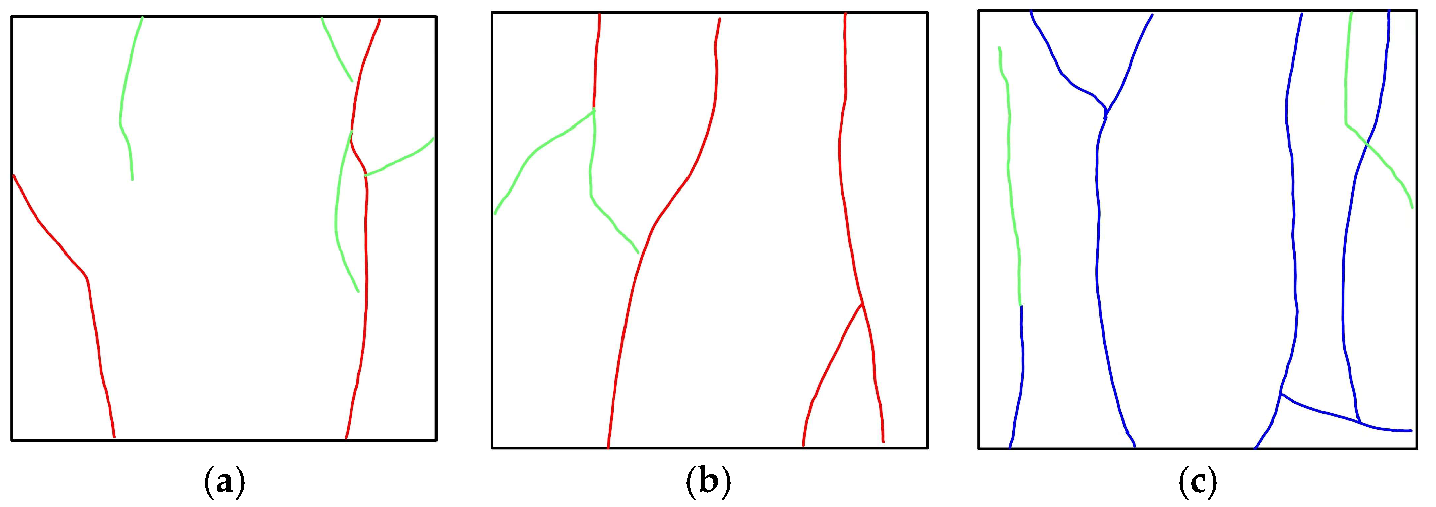
Figure 10.
Crack extension of specimens. (a) The ultra-fine cement grouting specimen; (b) The C-S grouting specimen; (c) The MARITHAN® grouting specimen. Note: the blue color represents the original rupture surface, the green color represents the nascent rupture surface, and the red color represents that the original rupture surface coincides with the nascent rupture surface.
From the perspective of strength reinforcement with grouting, the ultra-fine cement slurry and C-S slurry do not exhibit a good reinforcing effect due to their low adhesive properties and permeability. However, MARITHAN® can effectively improve the stress concentration caused by cracks, weaken the impact of prefabricated cracks on the macro-damage of the specimen, and exhibit a better reinforcing effect.
3.3. Analysis of Acoustic Emission Energy
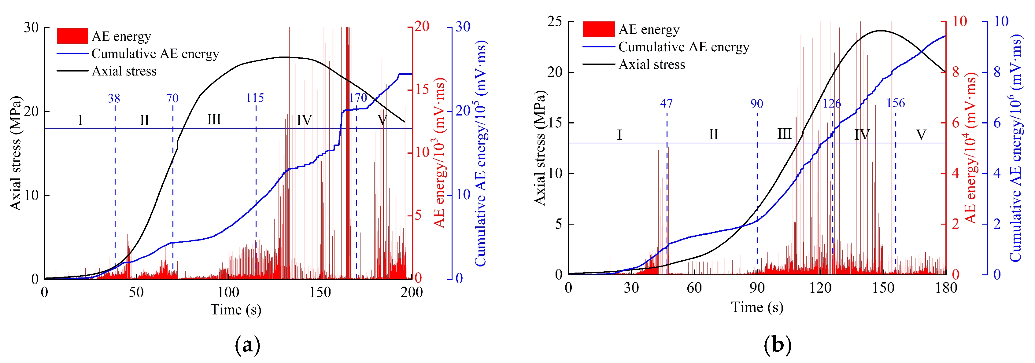
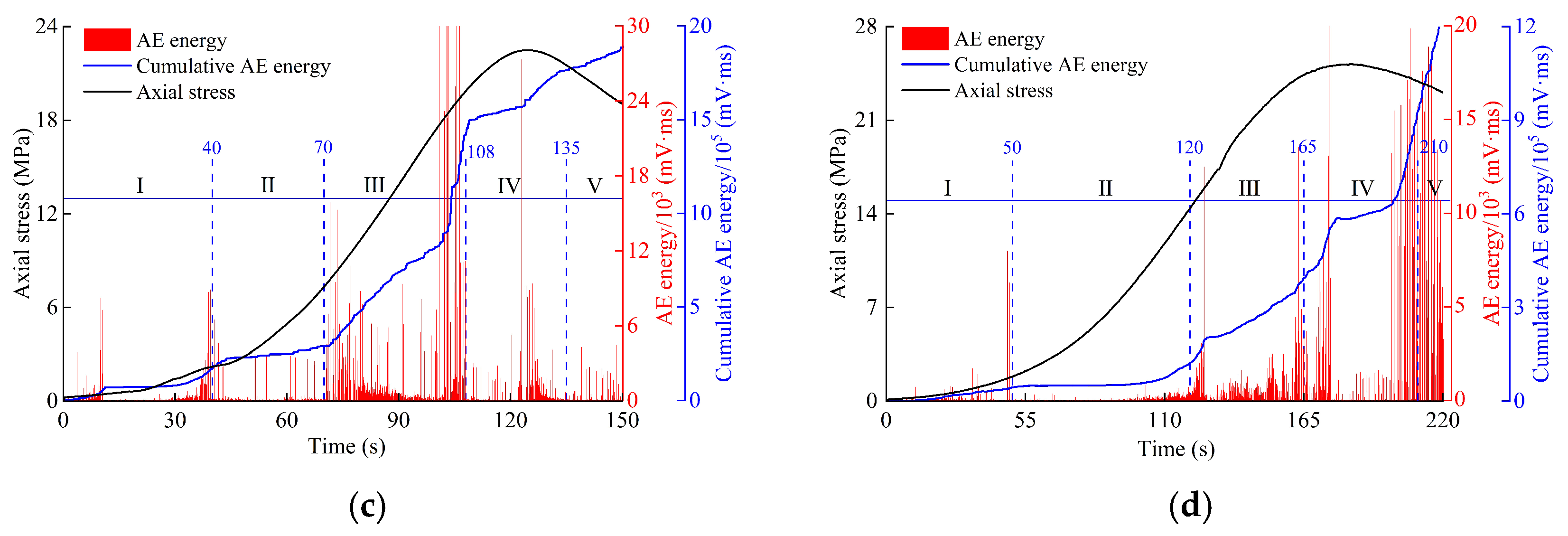
Acoustic emission (AE for short) energy represents the energy released from crack rupture, extension, and penetration during the deformation and damage process of the rock body, and its change characteristics are closely related to the internal damage evolution process of the rock body [15]. The AE energy generated in each deformation stage can be calculated to obtain the cumulative AE energy of the entire rock body deformation and damage process. Due to space constraints, several sets of typical AE energy relationship curves were selected for analysis, as shown in Figure 11. The AE energy parameters of the intact specimen and the grouting specimens are statistically presented in Table 4.

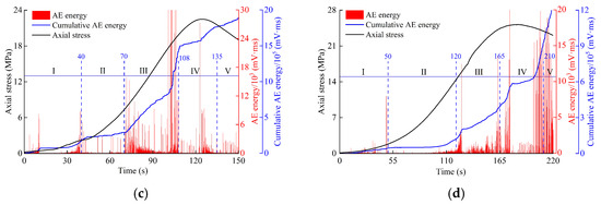
Figure 11.
AE statistics of fissure specimens with different grouting materials. (a) The intact specimen; (b) The ultra-fine cement grouting specimen; (c) The C-S grouting specimen; (d) The MARITHAN® grouting specimen.
Table 4.
AE energy parameters of different grouted specimens.
It can be seen from Figure 11 that the cumulative AE energy curves of the fissure specimens with different grouting materials generally show a downward concave step-type trend of change: the slope of the curve is small at low-stress levels; the growth rate of the curve increases gradually with the increase in axial stress; and the curve generally exhibits a slow then suddenly increasing trend as loading proceeds. According to the previous related literature [16,17,18], the curve is roughly divided into five stages: crack closure stage (I), elastic deformation stage (II), stable crack expansion stage (III), unstable crack expansion stage (IV), and post-peak damage stage (V). The AE characteristics of each stage are as follows:
Stage I: With the increase in load, the microcracks inside the specimen are gradually compacted and closed. Compared with the intact specimen, the cracks in the grouted specimen are compacted and closed for a longer period of time. The AE energy counts are increased at the end of this stage, and the slope of the cumulative energy curve is increased.
Stage II: As the load continues to increase, the specimen undergoes elastic deformation, the AE energy counts are distributed more uniformly, and there is no significant change in the cumulative AE energy curve.
Stage III: When the axial load reaches cracking stress, the cracks start to sprout and expand stably, and compared with the previous two stages, the slope of the cumulative AE energy curve at this time increases, and the curve shows an upward trend. Compared with the intact specimen, the slope of the cumulative AE energy curve of the grouted specimen increases significantly, and the AE energy counts of the ultra-fine cement grouting specimen and the C-S grouting specimen reach larger values.
Stage IV: At this time, the internal microcracks of the specimen develop rapidly, and the cracks interconnect with each other, forming obvious macroscopic cracks and generating a large number of AE signals. The AE energy counts increase rapidly, and the slope of the cumulative AE energy curve continues to increase. When the stress reaches its peak, both the AE energy counts and the slope of the cumulative AE energy curve reach their maximum values at this stage.
Stage V: The AE activity in this stage is relatively gentle compared to the previous stage; the cumulative AE energy curve continues to rise, the slope of the curve decreases slightly, and when the axial stress–time curve decreases, brittle damage occurs in the specimen, and the AE energy count reaches its maximum value.
In summary, the AE energy counts of the grouted specimens increased compared to the intact specimen, the cumulative AE energy curve showed obvious stage characteristics, and the distribution characteristics differed depending on the grouting material. The AE energy value of the ultra-fine cement grouting specimen and the C-S grouting specimen increased sharply in Stage III, and there was a maximum value for the slope of the cumulative AE energy curve; the MARITHAN® grouting specimen and the intact specimen generated a large number of AE signals in Stage IV, and the maximum value for the slope of the cumulative AE energy curve was in this stage. This indicates that a large number of cracks were generated in the ultra-fine cement grouting specimen and C-S grouting specimen in Stage III, and the ultra-fine cement slurry and C-S slurry have limited effects on the repair of internal damage to the specimen. It can be seen from Table 4, compared with other grouting specimens, the cumulative AE energy and peak AE energy of the MARITHAN® grouting specimen were the smallest, while the peak axial stress was the largest, indicating that MARITHAN® played a better grouting reinforcement effect.
4. Conclusions
The following conclusions can be made:
- (1)
- Analysis from the perspective of grouted strength: The method of grouting reinforcement can improve the residual strength of the specimens to a certain extent, and the residual strength enhancement coefficient varies depending on the grouting material used; the residual strength of the ultra-fine cement grouting specimen was increased by 16.931%, the residual strength of the C-S grouting specimen was increased by 13.075%, and the residual strength of the MARITHAN® grouting specimen was increased by 39.998%. However, the peak strengths of the three types of grouted specimens were still reduced compared to the intact specimens, and their peak strength enhancement coefficients were negative, indicating that there is a limit to the increase in strength depending on the grouting method.
- (2)
- Analysis from the perspective of damage patterns: The damage pattern of the ultra-fine cement grouting specimen and the C-S grouting specimen showed shear-slip damage along the original rupture surface. The MARITHAN® grouting specimen was cracked from a position near the end of the specimen, and the grouting body was not damaged. This indicates that the ultra-fine cement slurry and C-S slurry do not exert very good reinforcing effects due to their low adhesion and permeability and that MARITHAN® can effectively improve the stress concentration caused by the crack, weaken the influence of prefabricated cracks on the macro-damage of the specimen, and exert a better reinforcing effect.
- (3)
- Analysis from the perspective of AE energy: The cumulative AE energy curves of grouted specimens showed obvious stage characteristics, and the distribution characteristics differed depending on the grouting material used. The AE energy value of the ultra-fine cement grouting specimen and the C-S grouting specimen increased sharply in Stage III, and there was a maximum value for the slope of the cumulative AE energy curve. The MARITHAN® grouting specimen and the intact specimen produced a large number of AE signals in Stage IV, and the maximum value for the slope of the cumulative AE energy curve was in this stage. This indicates that a large number of cracks were generated in the ultra-fine cement grouting specimen and C-S grouting specimen in Stage III, and the ultra-fine cement slurry and C-S slurry exert limited effects on the repair of internal damage to the specimen.
5. Discussion
In this paper, the rock-like specimens with strength similar to the engineering surrounding rock were made through the calculation of the proportion, and after the completion of the maintenance, the uniaxial loading test was carried out to obtain the mechanical parameters of the specimens, and the fissure specimens close to the damage morphology of the engineering surrounding rock were obtained. Ultra-fine cement slurry, cement-silicate slurry, and MARITHAN® were used to carry out grouting reinforcement tests on the fissure specimens, and after the completion of the maintenance, uniaxial loading tests were carried out on them again, and the reinforcing effect of the grouting materials on the fractured surface of the rock-like specimens was analyzed in depth by combining with the acoustic emission signals.
The results of the study show that although grouting reinforcement can improve the mechanical properties of the fractured rock body, the strength is still reduced compared with the original rock, and the repair effect of grouting reinforcement is limited. This conclusion is basically consistent with the previous research results. Compared with ultra-fine cement slurry and cement-silicate slurry, MARITHAN® can effectively improve the stress concentration caused by cracks, weaken the impact of prefabricated cracks on the macro-damage of the specimen, and exhibit a better reinforcing effect. When discussing the reinforcing effect of grouting, we monitored and analyzed the uniaxial loading process of the specimen by using acoustic emission signals, which revealed the damage and destruction process of the grouted specimen and made up for the insufficiency of the previous researchers, who only paid attention to the mechanical properties of the grouted specimen when studying the reinforcing effect of grouting.
In addition to the above conclusions, it is worth further discussion that the essence of grouting reinforcement is the penetration cementation of the rupture surface. Although the combination of uniaxial loading and acoustic emission can satisfy the purpose of analyzing the effect of grouting reinforcement, it fails to reveal the cementation mechanism of the slurry with the rupture surface at the microscopic level. Further in-depth analysis of the mechanical properties of the structural surfaces using a scanning electron microscope is the focus of our research in the next experiment.
Author Contributions
Conceptualization, Z.Y. and C.S.; validation, Z.Y.; investigation, C.S.; writing—original draft preparation, C.S.; project administration, Z.Y. All authors have read and agreed to the published version of the manuscript.
Funding
This research was funded by the Anhui Provincial Natural Science Foundation (General Program; grant number: 1808085MG212).
Institutional Review Board Statement
Not applicable.
Informed Consent Statement
Not applicable.
Data Availability Statement
The data that support the findings of this study are available from the corresponding author upon reasonable request.
Conflicts of Interest
The authors declare no conflict of interest.
References
- She, S.G.; Lin, P. Some developments and challenging issues in rock engineering field in China. Chin. J. Rock Mech. Eng. 2014, 33, 433–457. [Google Scholar]
- Xu, Y.C.; Li, K.Q.; Xie, X.F.; Liu, S.Q.; Lyu, B. Grouting reinforcement of fractured rock mass based on damage mechanics. J. Xi’an Univ. Sci. Technol. 2017, 37, 26–31. [Google Scholar]
- Liu, Q.S.; Lei, G.F.; Lu, C.B.; Peng, X.X.; Zhang, J.; Wang, J.T. Experimental study of grouting reinforcement influence on mechanical properties of rock fracture. Chin. J. Rock Mech. Eng. 2017, 36, 3140–3147. [Google Scholar]
- Wang, Z.; Qin, W.J.; Zhang, L.J. Experimental study on static and dynamic mechanical properties of cracked rock after grouting reinforcement. Chin. J. Rock Mech. Eng. 2020, 39, 2451–2459. [Google Scholar]
- Shen, J.; Liu, B.G.; Chen, J.; Li, Y.F.; Cheng, Y.; Song, Y. Experimental study on mechanical properties of diabase fracture-grouting mass. Chin. J. Rock Mech. Eng. 2020, 39, 2804–2817. [Google Scholar]
- Zhang, J.F.; Xu, R.P.; Liu, Y.; Zhang, H.M. Study on micro-pore evolution law and shear mechanical behavior of grouting fractured rock mass under freeze-thaw cycle. Chin. J. Rock Mech. Eng. 2022, 41, 676–690. [Google Scholar]
- Wang, H.P.; Gao, Y.F.; Li, S.C. Uniaxial experiment study on mechanical properties of reinforced broken rocks pre-and-post grouting. Chin. J. Undergr. Space Eng. 2017, 3, 27–31+39. [Google Scholar]
- Yan, G.C.; Bai, L.J.; Zhang, Z.Q.; Yang, T.; Liu, J.H. Experimental and applied study on PU modified sulpho-aluminate cement grouting material. J. China Coal Soc. 2020, 45, 747–754. [Google Scholar]
- Zhu, H.W.; Liu, C.W.; Chen, X.Q.; Zhao, C. Experimental study on mortar materials with fissures filled with high permeability modified epoxy resin. Bull. Chin. Ceram. Soc. 2021, 40, 77–82. [Google Scholar]
- Zhu, Y.J.; Ren, H.; Wang, P.; Li, P.; Wang, X.Z.; Wei, M.X. Grouting test and reinforcement mechanism analysis of rock with single penetrated fracture surface. Rock Soil Mech. 2022, 43, 3221–3230. [Google Scholar]
- Su, D.G. Civil Engineering Materials, 4th ed.; Higher Education Press: Beijing, China, 2019. [Google Scholar]
- Han, L.J.; Zong, Y.J.; Han, G.L.; Zhang, H.Q. Study of shear properties of rock structural plane by grouting reinforcement. Rock Soil Mech. 2011, 32, 2570–2576+2622. [Google Scholar]
- Le, H.L.; Sun, S.R. Effect of grouting materials and inclination angle of pre-existing flaw on uniaxial compressive strength and failure mode of rock-like specimens. Rock Soil Mech. 2018, 39, 211–219. [Google Scholar]
- Feng, G.R.; Fan, Y.J.; Wang, P.F.; Guo, J.; Wen, X.Z.; Qian, R.P.; Zhu, L.J.; Zhang, P.F. Analysis of damage and failure process of rock-like specimens under uniaxial compression with different material combinations and ratios. Chin. J. Rock Mech. Eng. 2023, 42, 3377–3390. [Google Scholar]
- Liu, D.Q.; Guo, Y.P.; Li, J.Y.; Ling, K.; Yang, Y.Y.; Zhang, S.D. Damage evolution and constitutive model of brittle rock under uniaxial compression based on acoustic emission. J. China Univ. Min. Technol. 2023, 52, 687–700. [Google Scholar]
- Yao, Q.L.; Chen, T.; Tang, C.J.; Sedighi, M.; Wang, S.W.; Huang, Q.X. Influence of moisture on crack propagation in coal and its failure modes. Eng. Geol. 2019, 258, 105156. [Google Scholar] [CrossRef]
- Li, Y.; Liu, Y.; Ding, C.; Li, Z.L.; Zhang, X.F.; Ding, X.P. RA-AF characteristics of acoustic emission in uniaxial compression failure of different bedded coal. Saf. Coal Mines 2022, 53, 37–43. [Google Scholar]
- Wang, G.L.; Wang, R.Q.; Sun, F.; Cao, T.C. RA-AF characteristics of acoustic emission and failure mode of karst-fissure limestone under uniaxial compression. China J. Highw. Transp. 2022, 35, 118–128. [Google Scholar]

Disclaimer/Publisher’s Note: The statements, opinions and data contained in all publications are solely those of the individual author(s) and contributor(s) and not of MDPI and/or the editor(s). MDPI and/or the editor(s) disclaim responsibility for any injury to people or property resulting from any ideas, methods, instructions or products referred to in the content. |
© 2023 by the authors. Licensee MDPI, Basel, Switzerland. This article is an open access article distributed under the terms and conditions of the Creative Commons Attribution (CC BY) license (https://creativecommons.org/licenses/by/4.0/).