Abstract
The Vertical Take-Off and Landing (VTOL) system is a multi-variable system subjected to harsh weather conditions, which creates challenges in proving the stability of the system before takeoff, which is essential for a flight dynamics system. The presented research work is based on the experimental results of the VTOL system to investigate and prove the stability using Lyapunov theory. This is achieved by tracking the pitch along the x-axis using cascaded control and integral super twisting sliding mode control (ISTSMC) algorithms. The motor current of the propeller assembly is regulated based on proportional integral (PI) and proportional integral derivative (PID) controllers. The cascaded control shows the maximum tracking error due to high-frequency fluctuations in the controller input signal, which lead to expensive mechanical losses for the actuators. The comparison of the results shows that ISTSMC outperforms the cascaded control strategy by reducing the tracking error to less than 1% percent and reducing the high-frequency fluctuations in the controller input signal. The hardware results show a minor delay in the transient response during vertical takeoff due to the inertia of the system and the tracking error due to air friction, etc., of the external environment, compared to the simulation results obtained in MATLAB.
1. Introduction
The investigation of the applications of UAVs in the last few decades has increased tremendously, particularly regarding the monitoring of pests in the agriculture sector, security surveillance to monitor the borders to reduce smuggling, the tracking of theft in densely populated areas, the recording of crime scenes in metropolitan cities, fire detection and monitoring in forestry, the shipping and home delivery of various products, the supervision and monitoring of political and religious gatherings, geographic mapping, hazardous gas detection, and monitoring using various sensors [1,2,3]. The growing demand for UAVs in the current technological era reflects the scientific community’s attention towards the control of its various dynamics. An accurate dynamics model of the autonomous aerial vehicle can be investigated using various control algorithms. It has been a challenging research area since the 1990s, based on a feedback control system for VTOL vehicles [4,5]. VTOL vehicles have fewer requirements than fixed-wing aircraft for take-off and landing. VTOL’s capability in aerial vehicles removes the need for a runway and provides flexibility to operate in any domain [6]. The VTOL aircraft system can be sectioned into two parts: the flight mode and VTOL mode. The flight mode can be operated using a six-servo motor configuration. The first two servo motors are operated for roll control, the second two are operated by a ruddervator, and the last two are connected with brushless motors to drive the propellers on the left and right sides of the ailerons [7].
The autopilot mode regulates the aircraft pitch that the flight crew can use to reduce the workload during cruising and assist the aircraft to land in adverse weather conditions. At the plane’s rear section, the horizontal stabilizer attached to the tail is applied to regulate the pitch. The degree of the pitch of an aircraft is maintained by changing the angle and balancing the vertical lift of the rear elevator [8,9]. One example of a VTOL UAV is based on a ducted air fan craft that uses two main propellers to generate vertical thrust to ensure the vertical takeoff ability. It works with vector thrust to control the system’s dynamics by directing the thrust using the set of control surfaces [10]. The VTOL aircraft is an under-actuated system having six degrees of freedom (6-DoF), including three for translation and three for rotation. Hua developed a general framework of position, altitude, and velocity control based on a backstepping control strategy [11]. They proposed a multistage idea developed through a series of simpler controllers including velocity control, thrust direction control, and position control. Many researchers have extended the idea with the two-stage design strategy, developed through an outer translational control loop assigning the thrust vector by treating the air vehicle as a point mass [12,13,14]. Similarly, the inner altitude control loop applies a torque input to fix the thrust vector to the desired axis, controlling the vehicle headings simultaneously. Furthermore, the later stage is designed based on a backstepping control strategy.
Multiple researchers have formulated various control strategies and investigated the various aspects of the VTOL system, including stability analysis and position tracking compensation for various disturbances due to the real environment in harsh weather conditions [15,16,17,18,19]. Stingu designed and developed a VTOL UAV system based on proportional derivative controllers to regulate hover stability [16]. In addition, a nonlinear control algorithm was proposed to mitigate the aircraft control problem using dynamic control and feedback linearization methods, and they applied the backstepping control strategy and sliding mode control scheme. Efe initiated a sliding mode controller to control quadrotor robots at low altitudes. They achieved the desired elevations using a hierarchical control system and dynamic model for the aircraft [20]. Similarly, a PD control method with linear feedback and dynamic inverter control was applied to evaluate numerous VTOL UAV flight controls [21,22,23]. To enhance the stability of the flight dynamics system model, a predicative current control method was investigated, which included the number of candidate vectors, reflecting the vector selection more accurately. The amplitude of the vector can also be adjusted while suppressing ripples [24,25,26]. A sliding mode controller is a robust control strategy that alters the dynamics of a nonlinear system while applying a discontinuous control input. The vital significance of the sliding mode controller is its finite time convergence, insensitivity to interference, and sensitivity to steady-state error [27]. To address disturbances with finite time convergence properties, the integral terminal sliding mode control strategy has played a significant role in various UAVs. The integral terminal sliding mode control along with backstepping control was developed for altitude and position control [28]. This study performs a comprehensive stability analysis of the QNET VTOL system with an experimental investigation in LabVIEW and MATLAB using various control strategies, including cascaded control (PI, PID) and the ISTSMC nonlinear control algorithm.
The first core objective of the presented research work is to identify the significance of the nonlinear robust control technique for flight dynamics systems, which is obligatory to verify the stability of the VTOL system before takeoff. The presented work strengthens the stability analysis of the VTOL system using Lyapunov theory, showing the finite time convergence of the ISTSMC strategy and insensitiveness to disturbances. Moreover, ISTSMC is more immune to parametric variations, referred to as model uncertainties and disturbances that affect the VTOL system in terms of air pressure and friction, etc.
The next objective of the presented research is to compare the performance of ISTSMC with the cascaded control strategy. Linear control techniques such as PID are also compared as a reference, but they lack analysis in terms of verifying the stability of the VTOL system. The open loop analysis of the VTOL system after deriving the transfer function considering the air pressure and temperature of the ambient environment is simulated in MATLAB and LabVIEW using an experimental hardware setup. The actuator model in QNET VTOL consists of a DC motor used to drive the propellers and is primarily operated through a PI controller to investigate the altitude of the system in terms of pitch (deg) along the horizontal axis. The PI controller shows reduced performance in terms of tracking the error of pitch (deg) with oscillating behavior, and it deviates from the equilibrium position. The proportional, integral, and derivative gain of the PID controller for the current system is calculated using the polynomial method for the third-order system. The simulation analysis based on PID for the VTOL system achieved in MATLAB shows better performance than the experimental results achieved using LabVIEW in terms of the tracking of pitch (deg), overshoot, rise time, and steady-state error.
The last objective of this paper is to perform the experimental analysis of the VTOL system. ISTSMC is applied to overcome the magnitude of the tracking error being observed using a cascaded control strategy in a steady-state condition. The results presented show that ISTSMC outperforms the cascaded control algorithm.
The rest of the paper is organized as follows. Section 2 describes the mathematical model of the VTOL system, the actuator model, and the inner loop controller for the motor current of a propeller. Section 3 presents the control scheme design using cascaded control and ISTSMC for the VTOL system. Section 4 discusses the simulation results based on PI, PID, and ISTSMC and investigates the hardware implementation results. Section 5 contains the discussion and Section 6 provides the conclusions.
2. Mathematical Model of VTOL Platform with PI Control
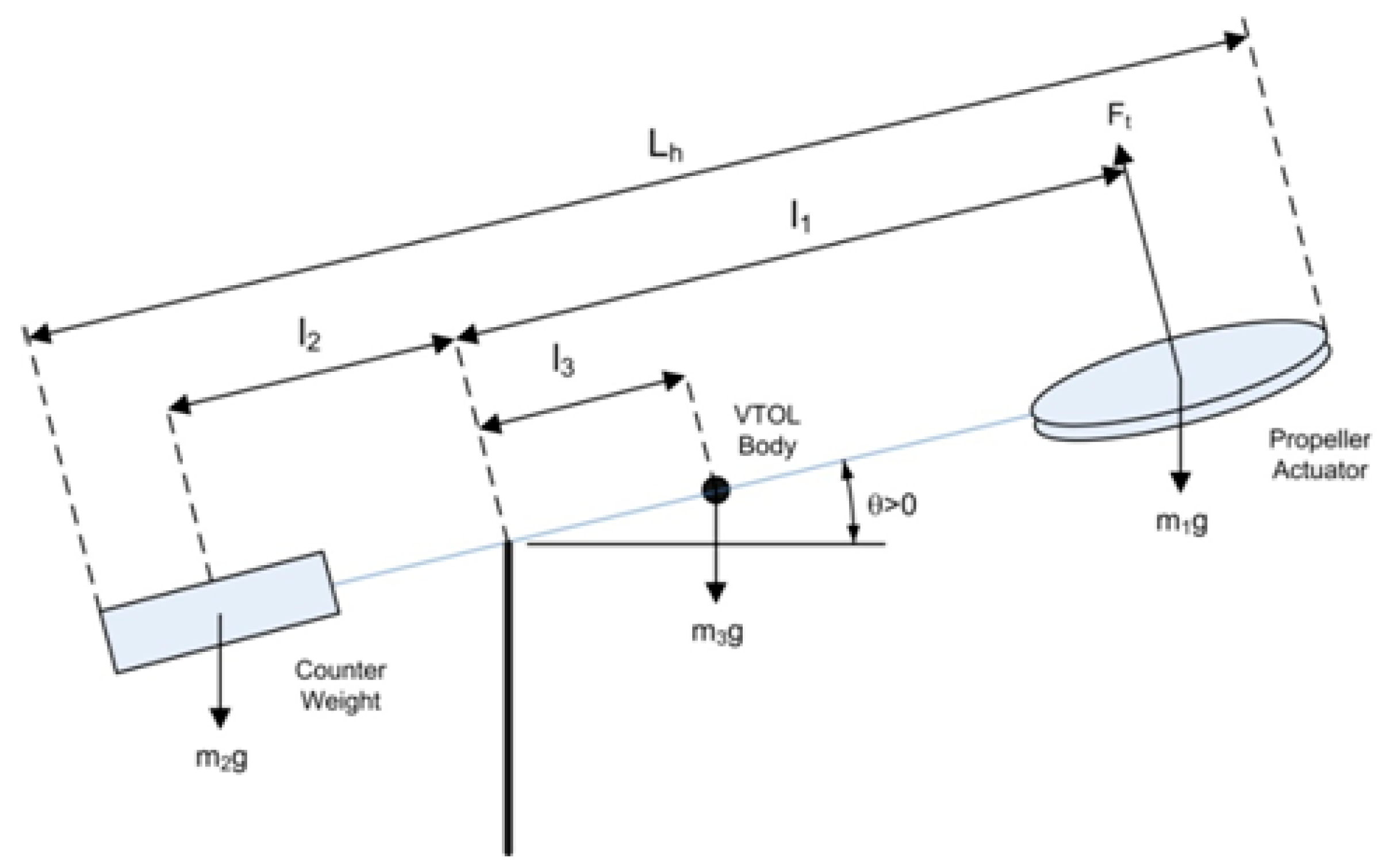
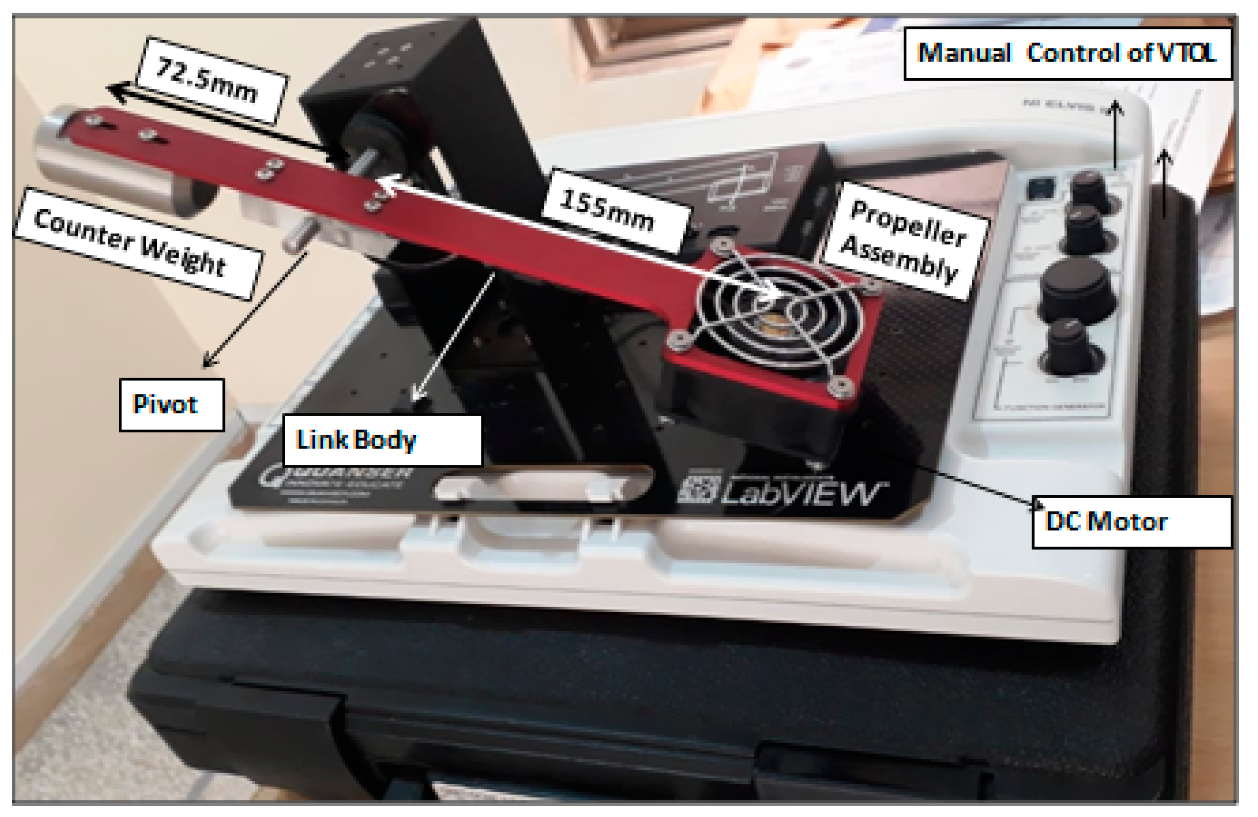
The diagram of the 1-DOF Quanser QNET 2.0 VTOL model is shown in Figure 1.
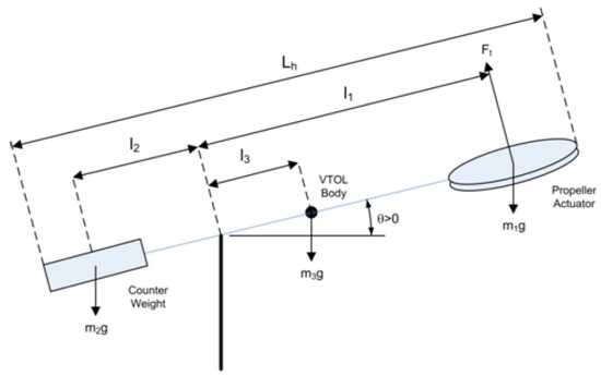
Figure 1.
Single DoF model of QNET VTOL system.
The VTOL system is a complete experimental setup used to investigate the dynamics of the aircraft along one axis (1 DOF), i.e., pitch. The propeller assembly acts as an actuator operated by a DC motor that provides uplift to the platform. The total length is divided into three segments, as shown in Figure 1, as , , and . The shows the angle of the platform and the horizontal axis will vary from . The various physical parameters of the VTOL system are described in Table 1.

Table 1.
Physical parameters of VTOL system.
The VTOL system is an electromechanical system, as shown in Figure 1. The thrust torque acting on the body, , is described in Equation (1) as
In Equation (1), is the pitch angle, and is the moment of inertia, which can be calculated as in Equation (2).
Expanding Equation (2) to find the moment of inertia for the VTOL system for in Figure 1 yields Equation (3) as
Placing the values of various parameters of the VTOL system into Equation (3) from Table 1 yields . The DC motor that operates the propeller assembly is a well-known rotational mechanical machine, and the torque of the DC motor is a significant parameter, expressed as , where is the thrust current torque constant measured in Nm/A. At the equilibrium position of the VTOL body along the horizontal axis, for . Thus, . At equilibrium, the value of . By simplifying and placing the values of various parameters in Equation (1), we have
The general model of the second-order system is described as
2.1. General Case for a Second-Order System
In a second-order system, if ζ < 0, the system is under-damped and the poles are a complex conjugate pair as .
Solving Equations (4) and (5) for the given VTOL system, we find that , which shows that the system is in an under-damped condition.
The performance parameters of the open-loop VTOL system are provided in the following Table 2.
Table 2.
Performance parameters of open-loop VTOL system.
2.2. Actuator Model of VTOL System
The actuator of the VTOL system is based on a DC motor used to operate the fan, which provides the uplift to the system. The following differential Equation (6) describes the actuator’s mathematical model of the system.
is the motor inductance, is the resistance of the motor, is the applied voltage to the motor, and is the motor current. Taking the Laplace transform of Equation (6) in Equation (7),
2.3. PI Controller for Actuator Model
An input voltage of 4V to 8V is applied to the DC motor to operate the propeller for the VTOL system. The PI controller is applied as an inner-loop controller, as shown in Figure 2. Figure 2 shows that the PI controller and VTOL system are connected in a cascaded fashion. The input to the actuator is voltage and the output is the motor current . The motor current is added to the PI controller as a feedback signal. The mathematical expression for the PI controller can be rewritten as
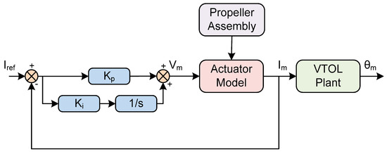
Figure 2.
Block diagram of the VTOL system and actuator model based on PI controller.
Taking the Laplace transform of Equation (8),
Considering the closed-loop configuration for the actuator model, placing the value of from Equation (7) in Equation (9), we have
By simplifying Equation (10), one has
Finally, rearranging Equation (11), we obtain the following expression:
Hence, the proportional and integral gains of the PI controller can be obtained by solving Equations (5) and (12) as
The block diagram of the VTOL system and actuator model based on the PI controller is shown in Figure 2.
3. Cascaded Controller and ISTSMC for the VTOL System
The two different control strategies, including the cascaded loop controller and ISTSMC, are applied for the VTOL system to investigate the various performance parameters, including the magnitude of the tracking error in terms of the platform’s pitch (deg) along the horizontal axis, the DC motor current, etc.
3.1. Cascaded Control Algorithm
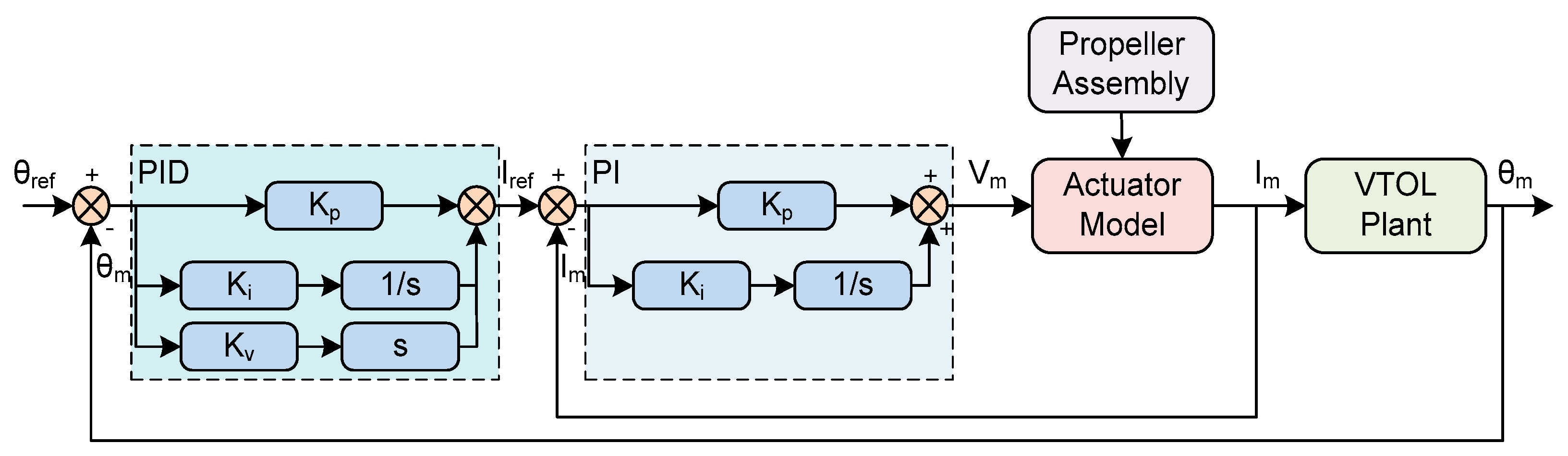
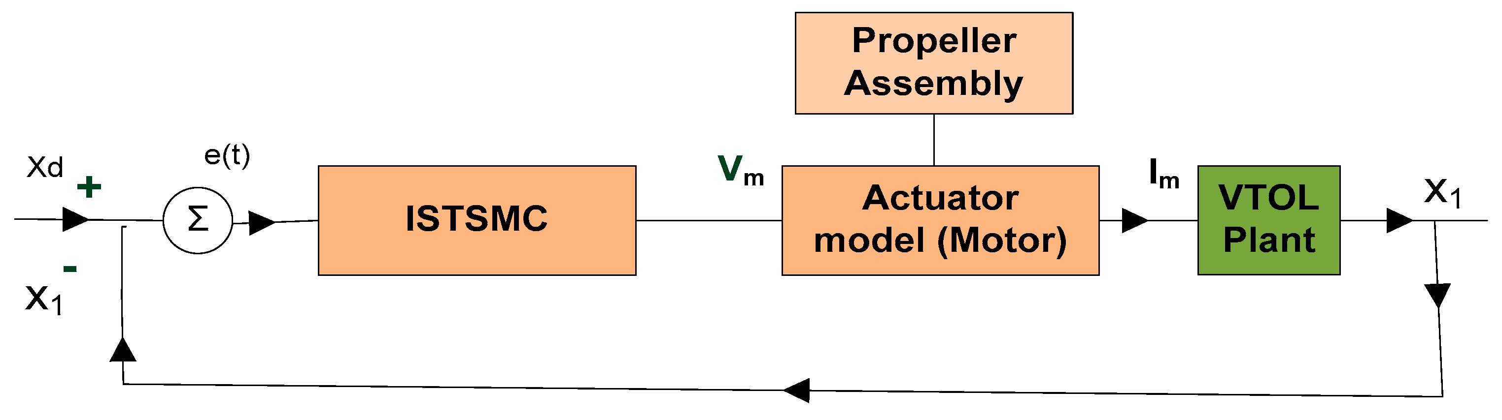
Figure 3 shows the cascaded control strategy based on PID and PI control for the VTOL system to track the to in the inner loop, referred to as a current control loop. This loop takes the measured value applied to the VTOL plant to the reference value . The DC motor operates the propeller assembly to attain the desired altitude. The outer loop is based on a PID controller that tracks the at the output side to the reference value in terms of the pitch (deg) of the aluminum arm of the VTOL body along the horizontal axis.
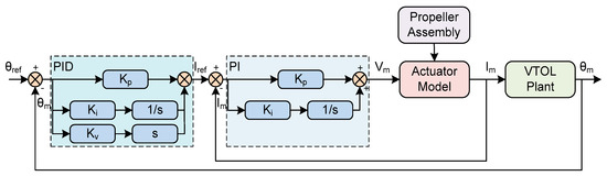
Figure 3.
Complete functional block diagram of closed-loop VTOL system based on cascaded loop controller.
The PID control topology in [29,30] can be redefined for the VTOL system as
Applying the Laplace transform to Equation (14),
Substituting the value of as an input to the plant in Equation (15) from Equation (4), we have
Rearranging Equation (16), we obtain
Finally, simplifying Equation (17), we have
The roots of the third-order characteristic polynomial equation can be defined as percent overshoot:
The gains of the PID controller can be derived by comparing Equation (18) with Equation (19) as
Hence, the following gain values of the PID controller are obtained by substituting various parameters in Equation (20):
3.2. ISTSMC for VTOL System
The ISTSMC-based control algorithm is applied to ensure robustness and reduce the tracking error magnitude so that the desired VTOL system’s pitch level is maintained. The state equation for the VTOL system is derived as follows:
The is the input to the VTOL system in terms of the motor current, and is the pitch of the VTOL system along the horizontal axis. To achieve the required performance, the following sliding surface is selected for the VTOL system [31,32,33,34,35,36,37,38,39].
The is the slope of the sliding surface, as the sliding surface implies that converges asymptotically to zero as
The following control law is designed by taking the derivative of the sliding surface:
The supertwisting-based reachability is proposed in Equation (26) to ensure the finite time convergence of the sliding mode [36].
where and are the control gains. Now, comparing the value from Equations (25) and (26), one obtains
Equation (26) is simplified to compute the controller input as
Validation of Control Law
The stability of the proposed ISTSMC for the VTOL system is based on the nonlinear Lyapunov stability theorem. The existence of a sliding mode can be proven by selecting the following Lyapunov candidate function:
The derivative of the Lyapunov candidate function must be negative definite within the state space of the VTOL system to converge the system dynamics to the desired set point. The first-order derivative of the Lyapunov candidate function is given as
Equation (30) is expanded by taking the value of from Equation (26),
Finally, Equation (31) is simplified as
Now, if is negative definite, then the ISTSMC is a stable control strategy for the VTOL system. The closed-loop diagram for the VTOL system based on ISTSMC is shown in Figure 4.

Figure 4.
Closed-loop system for VTOL system based on ISTSMC.
4. Simulation Results Using PI, PID, and ISTSMC Strategy
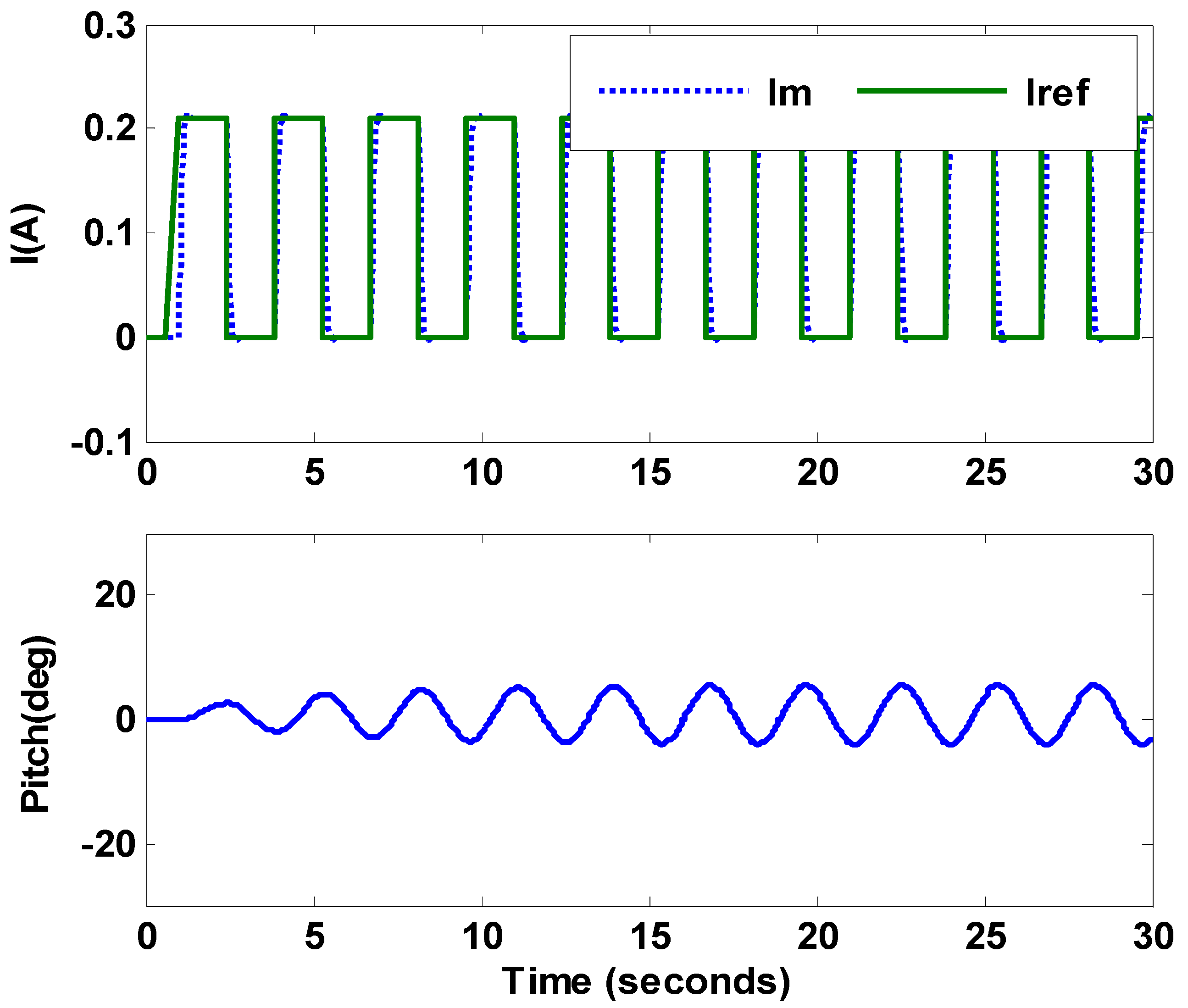
Figure 5 shows the performance of the PI controller in a MATLAB simulation when tracking the desired value of motor current , which varies from 0A to 0.21A in pulsating form. The in Figure 5 shows the measured value of the motor current, with a minor deviation from . Figure 5 also shows the pitch (deg) of the VTOL system along the horizontal axis based on the PI controller. The input to the VTOL system is , which varies from 0 A to 0.21 A; this leads to the operation of the VTOL propeller assembly and initiates vertical uplift to attain the equilibrium position at 0°. In addition, the VTOL assembly faces fluctuations when varying the pitch (deg) from −5° to 5°. The tracking error in steady-state conditions shows the reduced performance of the PI controller simulated in MATLAB, as shown in Figure 5.
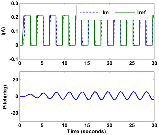
Figure 5.
Pitch of the VTOL system and motor current of actuator model based on PI controller.
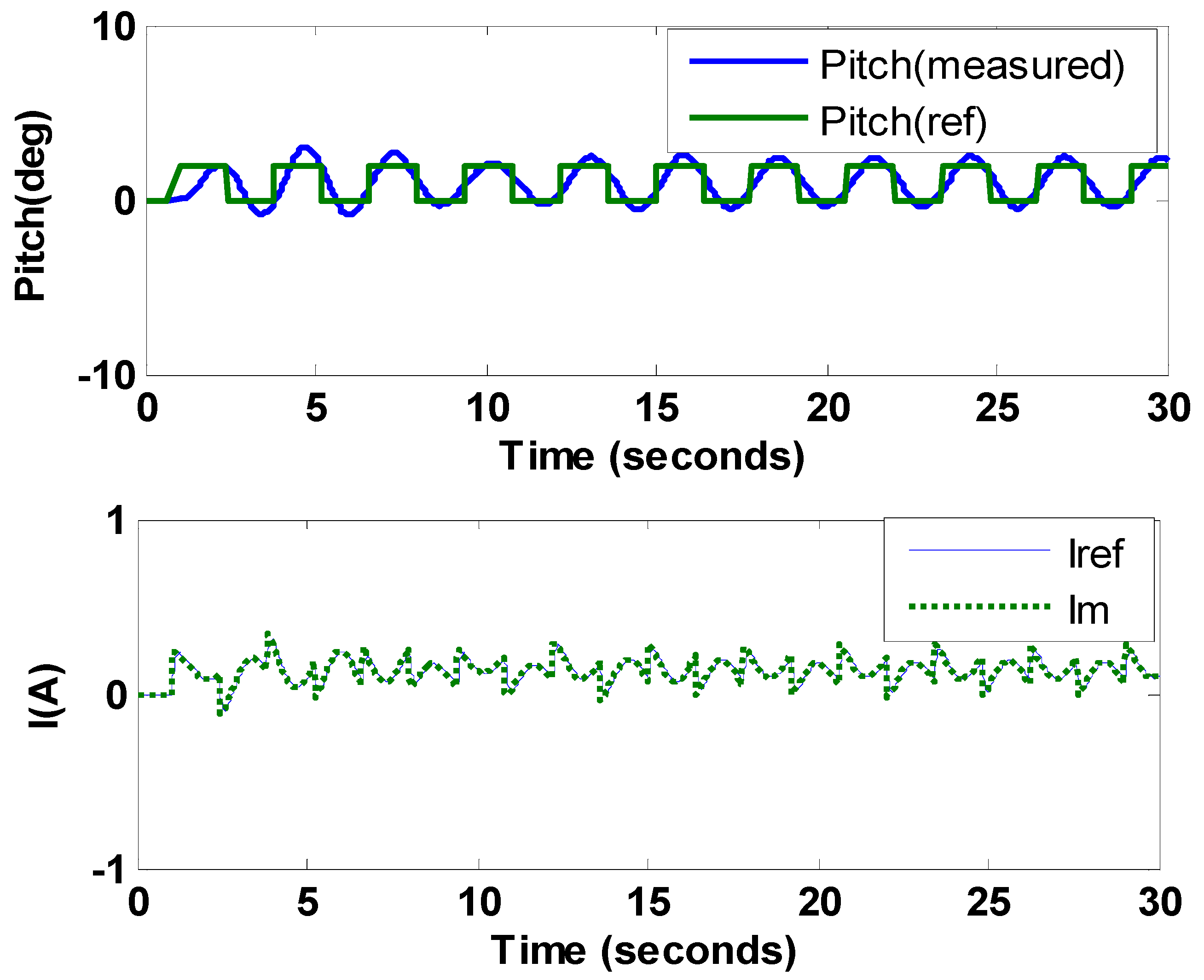
Figure 6 shows the results achieved in MATLAB based on the cascaded loop controller for the VTOL system. It shows the pitch in (deg) of the aluminum arm along the horizontal axis tracking the of the pulse generator signal with a period of 2.8 s, having a magnitude of pitch of two degrees along the horizontal axis and a pulse width of 50%. The tracking error is observed between and . Similarly, Figure 6 also shows the measured value of the motor accurately tracking the based on the PI controller in a current control loop for the actuator model.

Figure 6.
Pitch of the VTOL system and motor current of actuator model based on cascaded loop controller.
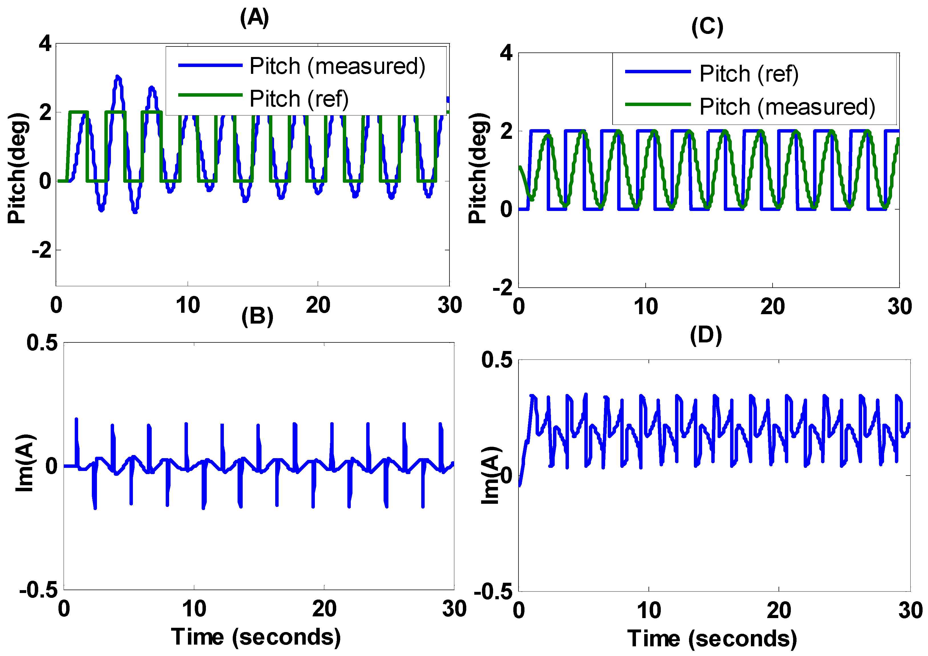
Figure 7 shows the comparative analysis between the cascaded loop controller based on PI as an inner loop tracking to , PID at the outer loop tracking to , and the nonlinear control strategy using ISTSMC. In addition, Figure 7A,B illustrate the pitch of the VTOL system tracking the pulse generator signal , as discussed in Figure 6, with showing the motor current used to operate the actuator of the VTOL system, respectively. A significant tracking error of nearly 40% of the final value is observed in Figure 7A for the PID controller. To reduce the magnitude of the tracking error, the ISTSMC algorithm is applied, with the results illustrated in Figure 7C,D demonstrating the pitch (deg) of the VTOL system and the motor current of the actuator model, respectively. It is shown in Figure 7C that the magnitude of the tracking error is reduced to less than 1%. A tracking delay is also observed, indicating a delay in the response of the VTOL system due to its inertia opposing the uplift provided by the propeller to the platform. As the motor current increases, the VTOL platform’s pitch is also increased to track the reference value as depicted in Figure 7D. Figure 7C confirms that the magnitude of the tracking error | − | decreases, leading to a significant decrease in , shown in Figure 7D, compared with Figure 7B, for the cascaded loop controller. Besides this, the controller input for ISTSMC, shown in Figure 7D, is more uniform and continuous compared to the cascaded loop controller shown in Figure 7B, where rapid fluctuations can be observed that lead to reduced reliability and cause mechanical losses.
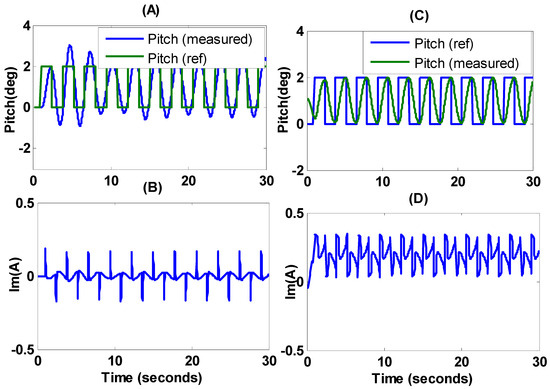
Figure 7.
(A–D) represent the pitch of the VTOL system and motor current of actuator model based on ISTSMC and cascaded loop controller.
Experimental Results Based on PI and Cascaded Controller
Figure 8 shows the experimental setup based on the QNET VTOL system. The 24 DC energizes the motor with 11,000 rpm connected to a solid aluminum arm. The circuit board of the QNET VTOL consists of a PWM voltage-controlled power amplifier that generates a peak current of 2 A and a continuous current of 0.5 A. The output voltage of the VTOL platform varies between 4 and 8 . The values of different physical parameters are shown and tabulated in Figure 8 and Table 1, respectively. The system is subjected to an ambient temperature of 28 degrees and humidity of 38% in the control and instrumentation lab of Balochistan University of Engineering and Technology Khuzdar, Pakistan.
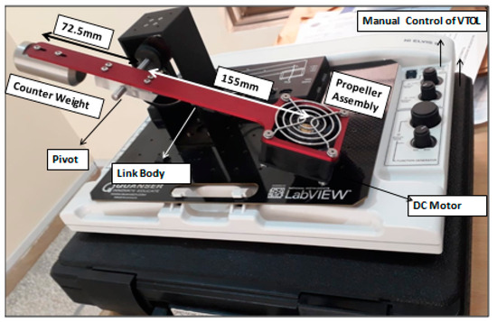
Figure 8.
Experimental setup of VTOL system.
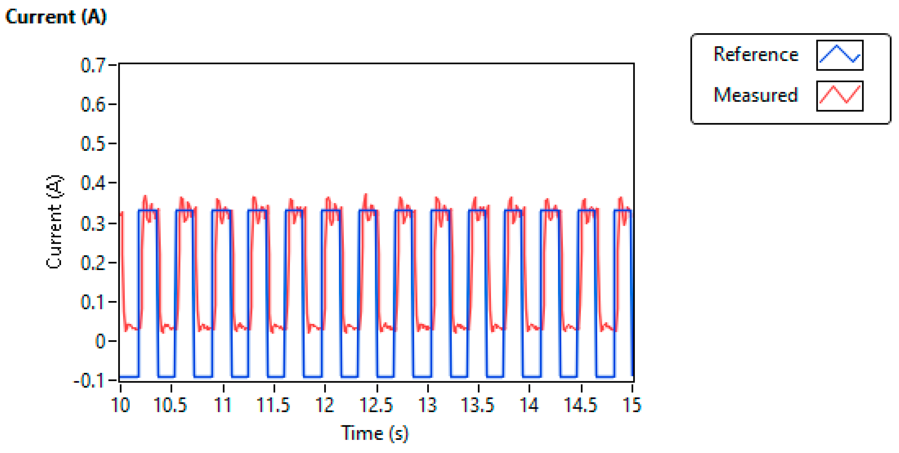
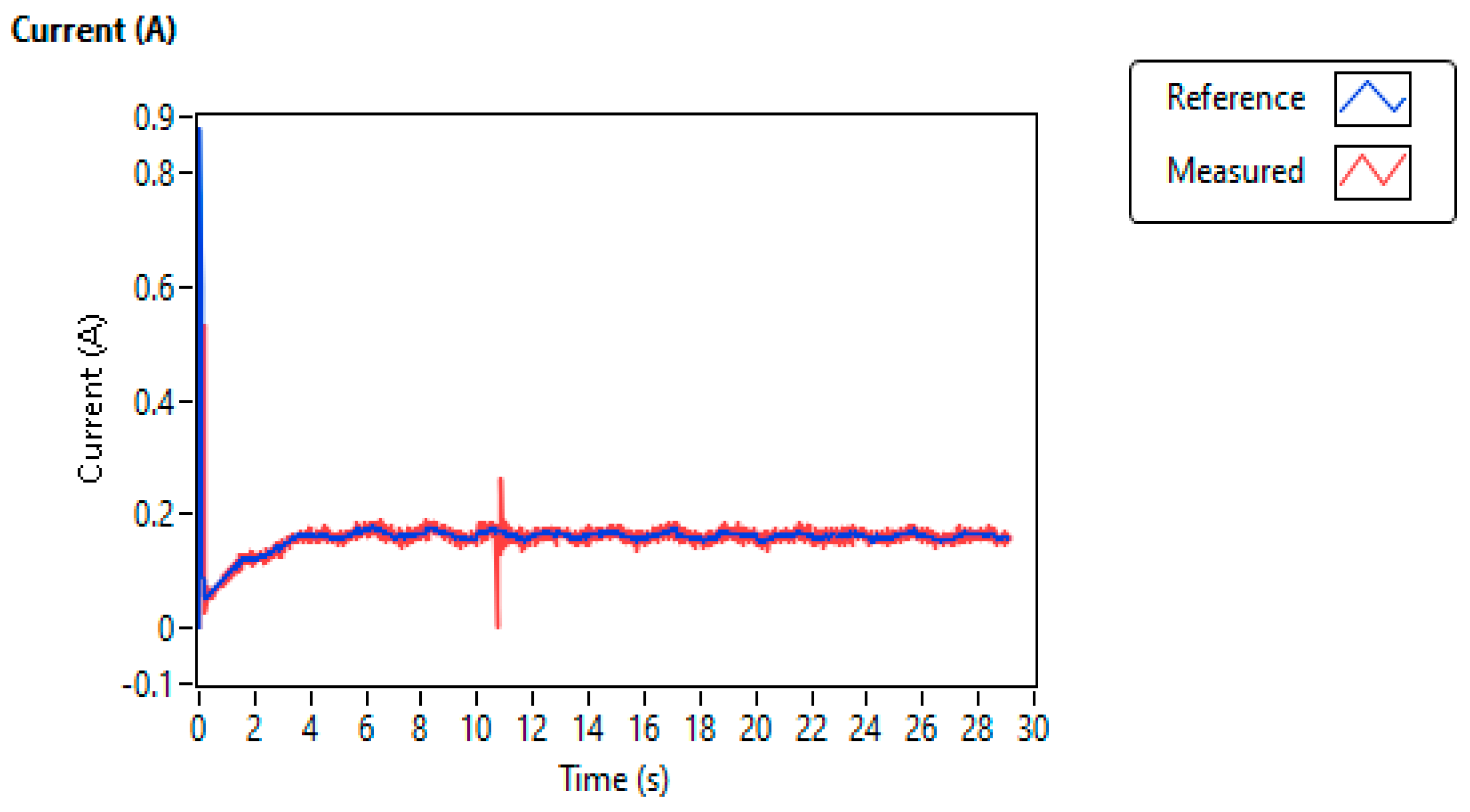
Figure 9 shows the motor current (red) of the propeller assembly with the (blue) as a reference current level. The motor current (red) of the propeller assembly tracking the (blue) as a reference current level is shown in Figure 9. The tracking performance of the motor current based on the PI controller using the experimental setup based on LabVIEW, shown in Figure 9, is closely mapped to Figure 5 based on the PI controller using MATLAB simulation. In this case, the hardware of the VTOL system is operated using a PI controller, with the gain calculated using Equation (12) as = 648 V/A and = 17.4 V/A.
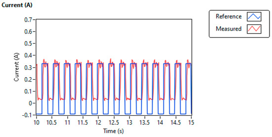
Figure 9.
VTOL motor reference current and output current in LabVIEW based on PI controller.
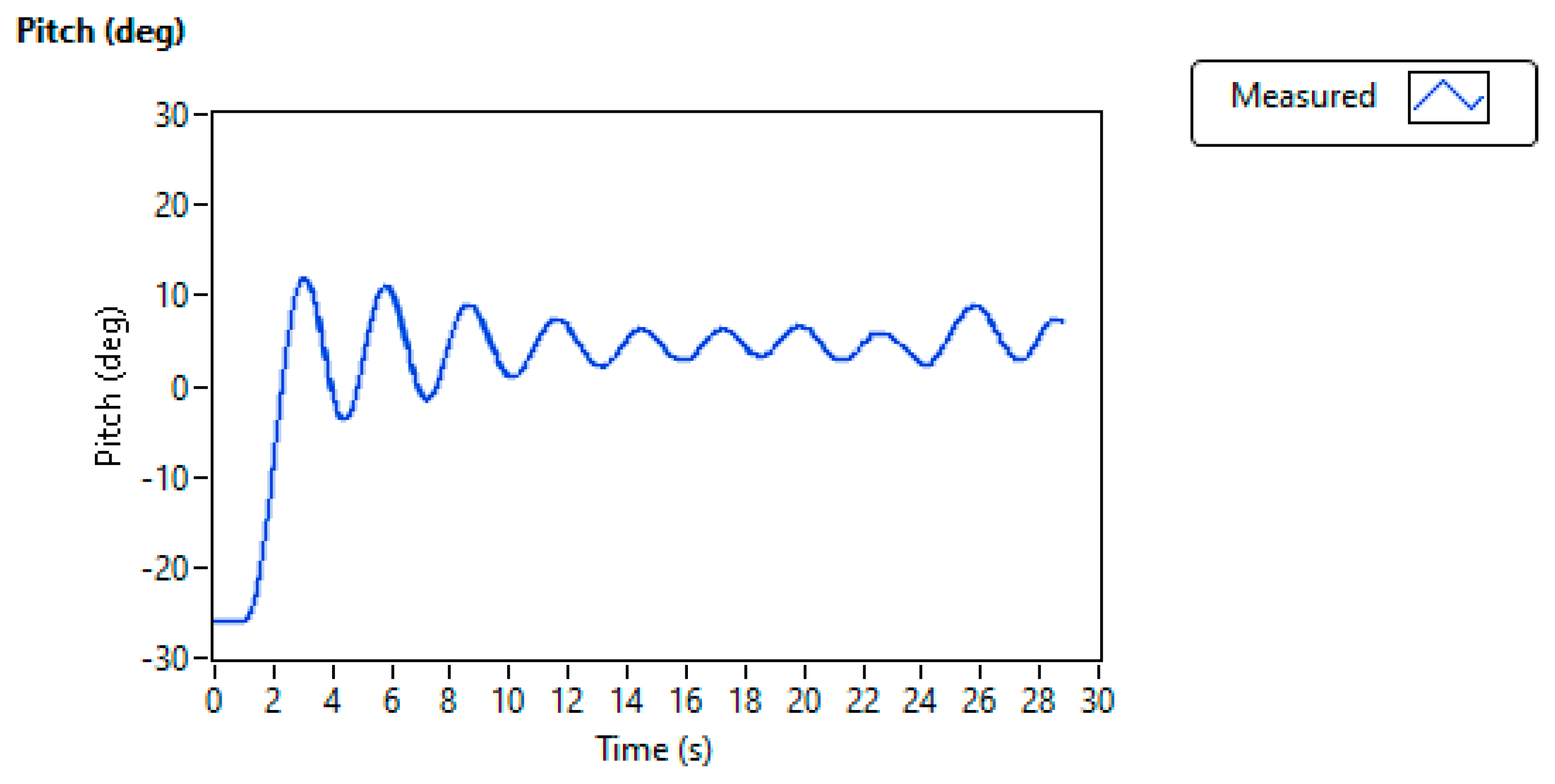
Figure 10 shows the pitch (deg) of the VTOL system while oscillating along the horizontal axis based on the PI controller. Initially, at static conditions, the aluminum arm of the VTOL system reaches an angle of along the horizontal axis. When switching the VTOL experimental setup and setting the pitch (deg) parameter of the aluminum arm, raising its position, and reflecting at above the horizontal position, the system oscillation decays slowly with a significant tracking error, as observed in the simulation conducted in MATLAB and as shown in Figure 5.
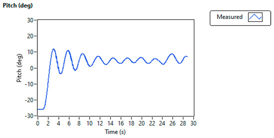
Figure 10.
VTOL pitch (deg) along horizontal axis in LabVIEW based on PI controller.
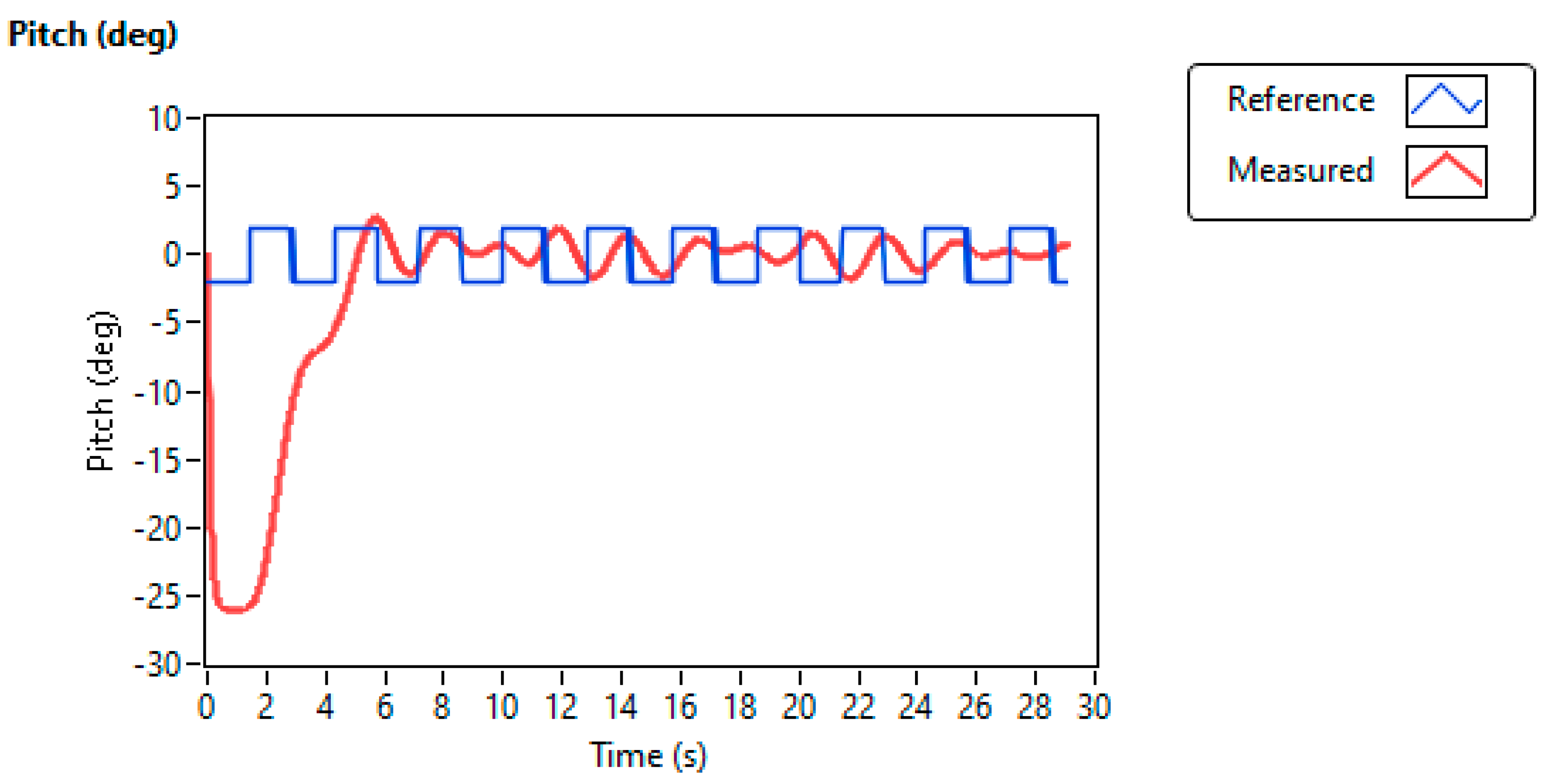
Figure 11 and Figure 12 show the pitch of the VTOL system with the actuator motor current tracking based on the cascaded control strategy using PID and PI in the LabVIEW platform interfaced with the QNET VTOL experimental setup, considering the values of , computed using Equation (21). The gains of the inner loop current controller are obtained as = 648 V/A and = 17.4 V/A. The results obtained using the experimental hardware setup are shown in Figure 11 and Figure 12, and they are closely mapped to the simulation analysis conducted in MATLAB, as shown in Figure 6. In Figure 11, the measured response of pitch shows slight delay due to the inertia of the overall VTOL assembly as compared to the reference value . The tracking the pulse generator signal has a frequency of 0.34Hz, magnitude of 2, and pulse width of nearly 50%. The experimental result based on the cascaded control strategy is better than that of the PI-based VTOL system shown in Figure 9 and Figure 10. The actuator motor current in Figure 12 accurately tracks the while fluctuating along the x-axis to converge to .
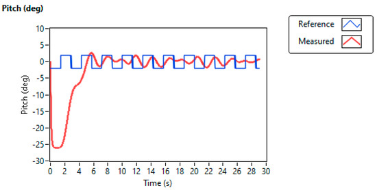
Figure 11.
Pitch (deg) of VTOL based on cascaded controller in LabVIEW.
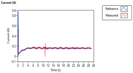
Figure 12.
Actuator model current based on cascaded controller for VTOL system in LabVIEW.
5. Discussion
The presented research work investigated the simulation results and hardware-based results of a flight dynamical system while focusing on PI, PID, and a robust control strategy referred to as ISTSMC. It is evident from the achieved results that a flight dynamical system such as a vertical takeoff and landing system, subjected to harsh weather conditions such as ambient air pressure, leads to variations in various parameters of the model, known as modeled uncertainties. In terms of addressing the parametric variations, ISTSMC outperformed the cascaded control mechanisms such as PI and PID for the flight dynamical system.
The analytical analysis of any control technique is significant to prove its stability.
The limitations of other control techniques, such as H Infinity, PID controllers, and fuzzy logic controllers, are evident for flight dynamical systems because we cannot verify the stability analysis after controller design. The significance of ISTSMC is clear due to the possibility for analysis after controller design as compared to other control strategies.
Furthermore, the presented research validated the stability analysis of the control law using Lyapunov theory and proved that the Lyapunov candidate function was negative definite as . In addition, the various performance parameters in the transient phase, including the peak time, overshoot, and steady-state response, as well as steady-state error, were also compared for both control strategies. In the closed-loop system, the input of the controller is quite significant for the lifespan of the actuator. If the variations in the control input signal are numerous and have high frequency, this leads to extensive mechanical vibrations and faults in the actuators due to fast switching. To minimize this fluctuation in the input signal, ISTSMC provides a uniform and smooth input signal to the actuator as compared to a cascaded control strategy based on PI or PID.
6. Conclusions
The study performed a stability analysis of the VTOL system using a cascaded control strategy and ISTSMC controller in MATLAB and LabVIEW, using experimental hardware setups. The analysis of ISTSMC was conducted by applying Lyapunov’s theory of stability while subjecting the VTOL system to ambient environmental conditions. The results achieved via the proposed ISTSMC control strategy showed that we significantly stabilized the aluminum arm of the VTOL system along the horizontal axis, with a tracking error of less than 1%, compared to the cascaded loop controller with nearly 40%. ISTMSC reduced the fluctuations in the controller input signal, which was the motor current provided to the VTOL system, reducing the mechanical losses. The research work can be further extended to reduce the fluctuations in the actuator current by applying robust control algorithms to enhance the lifespan of the VTOL actuator system.
Author Contributions
Conceptualization: M.I.; methodology: M.I. and S.A.; writing—original draft: M.I., I.S. and A.K.; data curation: S.A.; writing—review and editing: I.S., A.K. and S.A.; visualization: D.-W.J.; software: M.I. and I.S.; supervision: D.-W.J.; project administration: I.S., S.A. and D.-W.J.; funding acquisition; S.A. and D.-W.J. All authors have read and agreed to the published version of the manuscript.
Funding
This research was funded by the Brain Pool Program of the Ministry of Science and by ICT through the National Research Foundation of Korea (RS-2023-00218940).
Data Availability Statement
Not applicable.
Conflicts of Interest
The authors declare no conflict of interest.
References
- Bashi, O.I.D.; Hasan, W.W.; Azis, N.; Shafie, S.; Wagatsuma, H. Autonomous Quadcopter Altitude for Measuring Risky Gases in Hazard Area. J. Telecommun. Electron. Comput. Eng. (JTEC) 2018, 10, 31–34. [Google Scholar]
- Erginer, B.; Altuğ, E. Design and implementation of a hybrid fuzzy logic controller for a quadrotor VTOL vehicle. Int. J. Control. Autom. Syst. 2012, 10, 61–70. [Google Scholar] [CrossRef]
- Liu, Y.; Sun, G.; Chen, H. Impedance control of a bio-inspired flying and adhesion robot. In Proceedings of the IEEE International Conference on Robotics and Automation (ICRA), Hong Kong, China, 31 May–5 June 2014; pp. 3564–3569. [Google Scholar] [CrossRef]
- Bouabdallah, S.; Noth, A.; Siegwart, R. PID vs LQ control techniques applied to an indoor micro quadrotor. In Proceedings of the International Conference on Intelligent Robots and Systems (IROS) (IEEE Cat. No. 04CH37566), Sendai, Japan, 28 September–2 October 2004; Volume 3, pp. 2451–2456. [Google Scholar] [CrossRef]
- Erginer, B.; Altug, E. Modeling and PD control of a quadrotor VTOL vehicle. In Proceedings of the IEEE Intelligent Vehicles Symposium, Istanbul, Turkey, 13–15 June 2007; pp. 894–899. [Google Scholar] [CrossRef]
- Çakici, F.; Leblebicioğlu, M.K. Control system design of a vertical take-off and landing fixed-wing UAV. IFAC Pap. 2016, 49, 267–272. [Google Scholar] [CrossRef]
- Oo, W.; Tun, H.; Naing, Z.; Moe, W. Design of vertical take-off and landing (VTOL) aircraft system. Int. J. Sci. Technol. Res. 2017, 6, 179–183. [Google Scholar]
- Ang, K.H.; Chong, G.; Li, Y. PID control system analysis, design, and technology. IEEE Trans. Control Syst. Technol. 2005, 13, 559–576. [Google Scholar] [CrossRef]
- Rabah, M.; Rohan, A.; Han, Y.J.; Kim, S.H. Design of fuzzy-PID controller for quadcopter trajectory-tracking. Int. J. Fuzzy Log. Intell. Syst. 2018, 18, 204–213. [Google Scholar] [CrossRef]
- Roberts, A.; Tayebi, A. Adaptive position tracking of VTOL UAVs. IEEE Trans. Robot. 2010, 27, 129–142. [Google Scholar] [CrossRef]
- Hua, M.D.; Hamel, T.; Morin, P.; Samson, C. A control approach for thrust-propelled underactuated vehicles and its application to VTOL drones. IEEE Trans. Autom. Control 2009, 54, 1837–1853. [Google Scholar] [CrossRef]
- Abdessameud, A.; Tayebi, A. Global trajectory tracking control of VTOL-UAVs without linear velocity measurements. Automatica 2010, 46, 1053–1059. [Google Scholar] [CrossRef]
- Naldi, R.; Furci, M.; Sanfelice, R.G.; Marconi, L. Robust global trajectory tracking for underactuated VTOL aerial vehicles using inner-outer loop control paradigms. IEEE Trans. Autom. Control 2016, 62, 97–112. [Google Scholar] [CrossRef]
- Roberts, A.D. Attitude Estimation and Control of VTOL UAVs. Ph.D. Thesis, The University of Western Ontario, London, ON, Canada, 2011. [Google Scholar]
- Hedjar, R.; Al Zuair, M.A. Robust altitude stabilization of VTOL-UAV for payloads delivery. IEEE Access 2019, 7, 73583–73592. [Google Scholar] [CrossRef]
- Stingu, E.; Lewis, F. Design and implementation of a structured flight controller for a 6DoF quadrotor using quaternions. In Proceedings of the 17th Mediterranean Conference on Control and Automation, Thessaloniki, Greece, 24–26 June 2009; pp. 1233–1238. [Google Scholar] [CrossRef]
- Voos, H. Nonlinear control of a quadrotor micro-UAV using feedback-linearization. In Proceedings of the IEEE International Conference on Mechatronics, Málaga, Spain, 14–17 April 2009; pp. 1–6. [Google Scholar] [CrossRef]
- Madani, T.; Benallegue, A. Sliding mode observer and backstepping control for a quadrotor unmanned aerial vehicles. In Proceedings of the American Control Conference, New York, NY, USA, 9–13 July 2007; pp. 5887–5892. [Google Scholar] [CrossRef]
- Besnard, L.; Shtessel, Y.B.; Landrum, B. Control of a quadrotor vehicle using sliding mode disturbance observer. In Proceedings of the American Control Conference, New York, NY, USA, 9–13 July 2007; pp. 5230–5235. [Google Scholar] [CrossRef]
- Efe, M.O. Robust low altitude behavior control of a quadrotor rotorcraft through sliding modes. In Proceedings of the Mediterranean Conference on Control Automation, Athens, Greece, 27–29 June 2007; pp. 1–6. [Google Scholar] [CrossRef]
- Zhang, R.; Quan, Q.; Cai, K.Y. Attitude control of a quadrotor aircraft subject to a class of time-varying disturbances. IET Control Theory Appl. 2011, 5, 1140–1146. [Google Scholar] [CrossRef]
- Zhang, J.; Li, L.; Dorrell, D.G.; Guo, Y. Modified PI controller with improved steady-state performance and comparison with PR controller on direct matrix converters. Chin. J. Electr. Eng. 2019, 5, 53–66. [Google Scholar] [CrossRef]
- Hou, Q.; Ding, S.; Yu, X.; Mei, K. A super-twisting-like fractional controller for SPMSM drive system. IEEE Trans. Ind. Electron. 2021, 69, 9376–9384. [Google Scholar] [CrossRef]
- Xu, B.; Zhang, L.; Ji, W. Improved non-singular fast terminal sliding mode control with disturbance observer for PMSM drives. IEEE Trans. Transp. Electrif. 2021, 7, 2753–2762. [Google Scholar] [CrossRef]
- Xu, B.; Jiang, Q.; Ji, W.; Ding, S. An improved three-vector-based model predictive current control method for surfacemounted PMSM drives. IEEE Trans. Transp. Electrif. 2022, 8, 4418–4430. [Google Scholar] [CrossRef]
- Azid, S.I.; Shankaran, V.P.; Mehta, U. Fractional PI controller for integrating plants. In Proceedings of the 16th International Conference on Control, Automation, Robotics and Vision (ICARCV), Shenzhen, China, 13–15 December 2020; pp. 904–909. [Google Scholar] [CrossRef]
- Liu, Z.; Cai, W.; Zhang, M.; Lv, S. Improved integral sliding mode control-based attitude control design and experiment for high maneuverable AUV. J. Mar. Sci. Eng. 2022, 10, 795. [Google Scholar] [CrossRef]
- Dalwadi, N.; Deb, D.; Rath, J.J. Biplane trajectory tracking using hybrid controller based on backstepping and integral terminal sliding mode control. Drones 2022, 6, 58. [Google Scholar] [CrossRef]
- Duan, L.; Su, X.; Tang, Y.; Yang, H.; Zhang, H. Application of PID Tracking Control in Inverted Pendulum System. In Proceedings of the IEEE 4th Advanced Information Management, Communicates, Electronic and Automation Control Conference (IMCEC), Chongqing, China, 18–20 June 2021; Volume 4, pp. 1815–1819. [Google Scholar] [CrossRef]
- Kadu, C.B.; Patil, C.Y. Design and implementation of stable PID controller for interacting level control system. Procedia Comput. Sci. 2016, 79, 737–746. [Google Scholar] [CrossRef]
- Slotine, J.J.E.; Li, W. Applied Nonlinear Control; Prentice Hall: Englewood Cliffs, NJ, USA, 2009; Volume 199, p. 705. [Google Scholar]
- Yang, J.; Li, S.; Su, J.; Yu, X. Continuous nonsingular terminal sliding mode control for systems with mismatched disturbances. Automatica 2013, 49, 2287–2291. [Google Scholar] [CrossRef]
- Alam, W.; Mehmood, A.; Ali, K.; Javaid, U.; Alharbi, S.; Iqbal, J. Nonlinear control of a flexible joint robotic manipulator with experimental validation. Stroj. Vestn. J. Mech. Eng. 2018, 64, 47–55. [Google Scholar] [CrossRef]
- Ajwad, S.A.; Iqbal, J.; Islam, R.U.; Alsheikhy, A.; Almeshal, A.; Mehmood, A. Optimal and robust control of multi DOF robotic manipulator. Des. Hardw. Realiz. Cybern. Syst. 2018, 49, 77–93. [Google Scholar] [CrossRef]
- Chaouch, S.; Abdou, L.; Drid, S.; Chrifi-Alaoui, L. Optimized torque control via backstepping using genetic algorithm of induction motor. J. Control. Meas. Electron. Comput. Commun. 2016, 57, 379–386. [Google Scholar] [CrossRef]
- Ilyas, M.; Iqbal, J.; Ahmad, S.; Uppal, A.A.; Imtiaz, W.A.; Riaz, R.A. Hypnosis regulation in propofol anaesthesia employing super-twisting sliding mode control to compensate variability dynamics. IET Syst. Biol. 2020, 14, 59–67. [Google Scholar] [CrossRef]
- Aboud, W.S.; Al-Amir, H.S.A.; Alhamdany, A.A.; Kadhim, F.M. Overcome uncertainties of vertical take-off and landing aircraft based on optimal sliding mode control. Indones. J. Electr. Eng. Comput. Sci. 2023, 29, 703–714. [Google Scholar]
- Jia, T.; Chen, X.; He, L.; Zhao, F.; Qiu, J. Finite-time synchronization of uncertain fractional-order delayed memristive neural networks via adaptive sliding mode control and its application. Fractal Fract. 2022, 6, 502. [Google Scholar] [CrossRef]
- Jiang, J.; Xu, X.; Zhao, K.; Guirao, J.L.; Saeed, T.; Chen, H. The Tracking Control of the Variable-Order Fractional Differential Systems by Time-Varying Sliding-Mode Control Approach. Fractal Fract. 2022, 6, 231. [Google Scholar] [CrossRef]

Disclaimer/Publisher’s Note: The statements, opinions and data contained in all publications are solely those of the individual author(s) and contributor(s) and not of MDPI and/or the editor(s). MDPI and/or the editor(s) disclaim responsibility for any injury to people or property resulting from any ideas, methods, instructions or products referred to in the content. |
© 2023 by the authors. Licensee MDPI, Basel, Switzerland. This article is an open access article distributed under the terms and conditions of the Creative Commons Attribution (CC BY) license (https://creativecommons.org/licenses/by/4.0/).