
Effect of Wheel Path in Raster Grinding on Surface Accuracy of an Off-Axis Parabolic Mirror

Abstract
:1. Introduction
2. Materials and Research Methods
2.1. Experimental Details
2.2. Detection Method
3. Result
3.1. Scallop Height
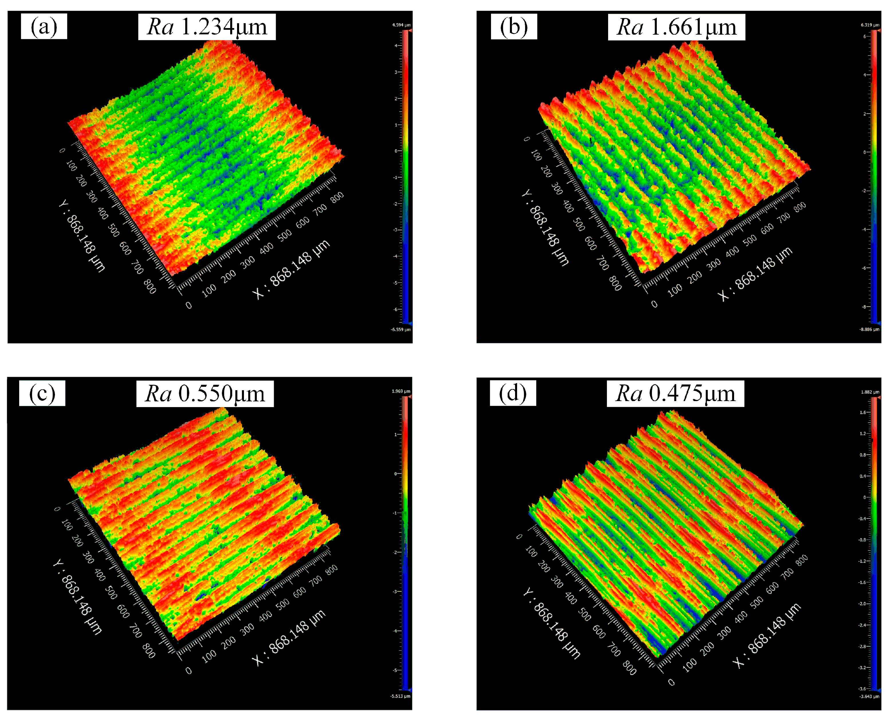
3.2. Surface Roughness
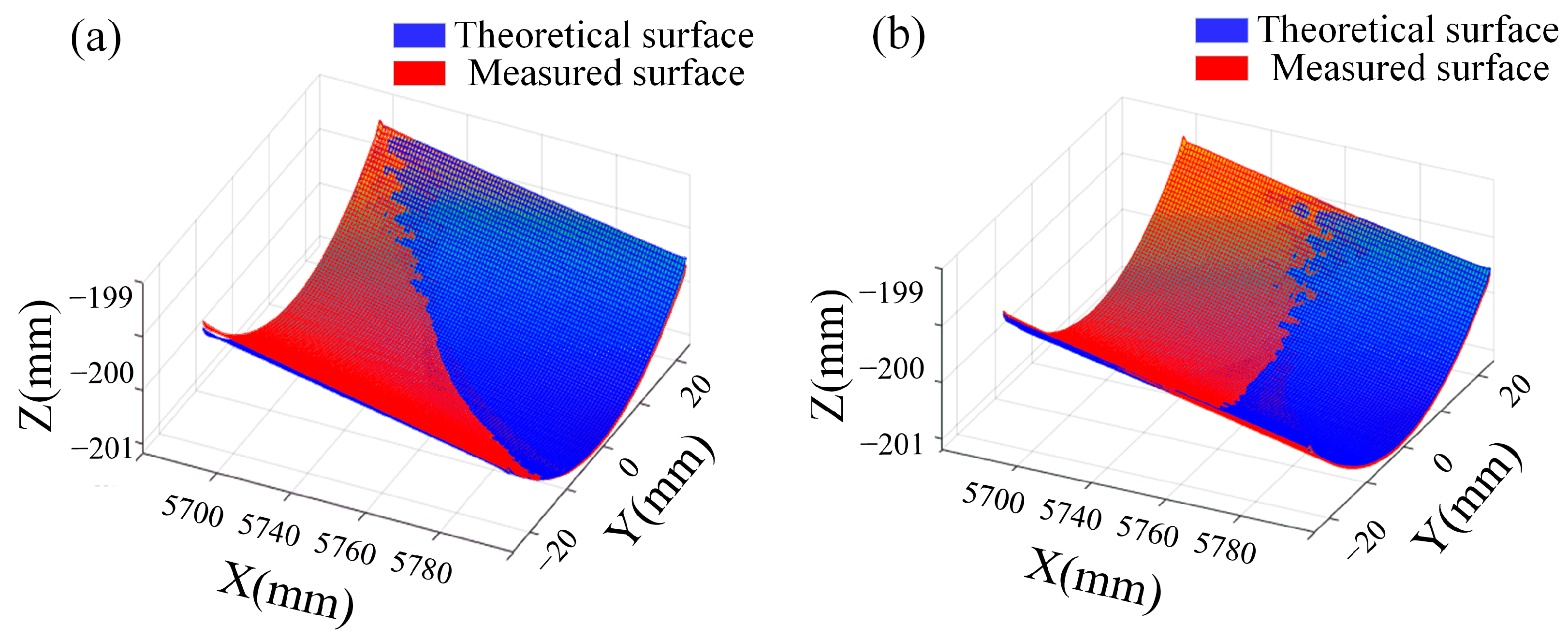
3.3. Surface Shape Error
4. Discussion
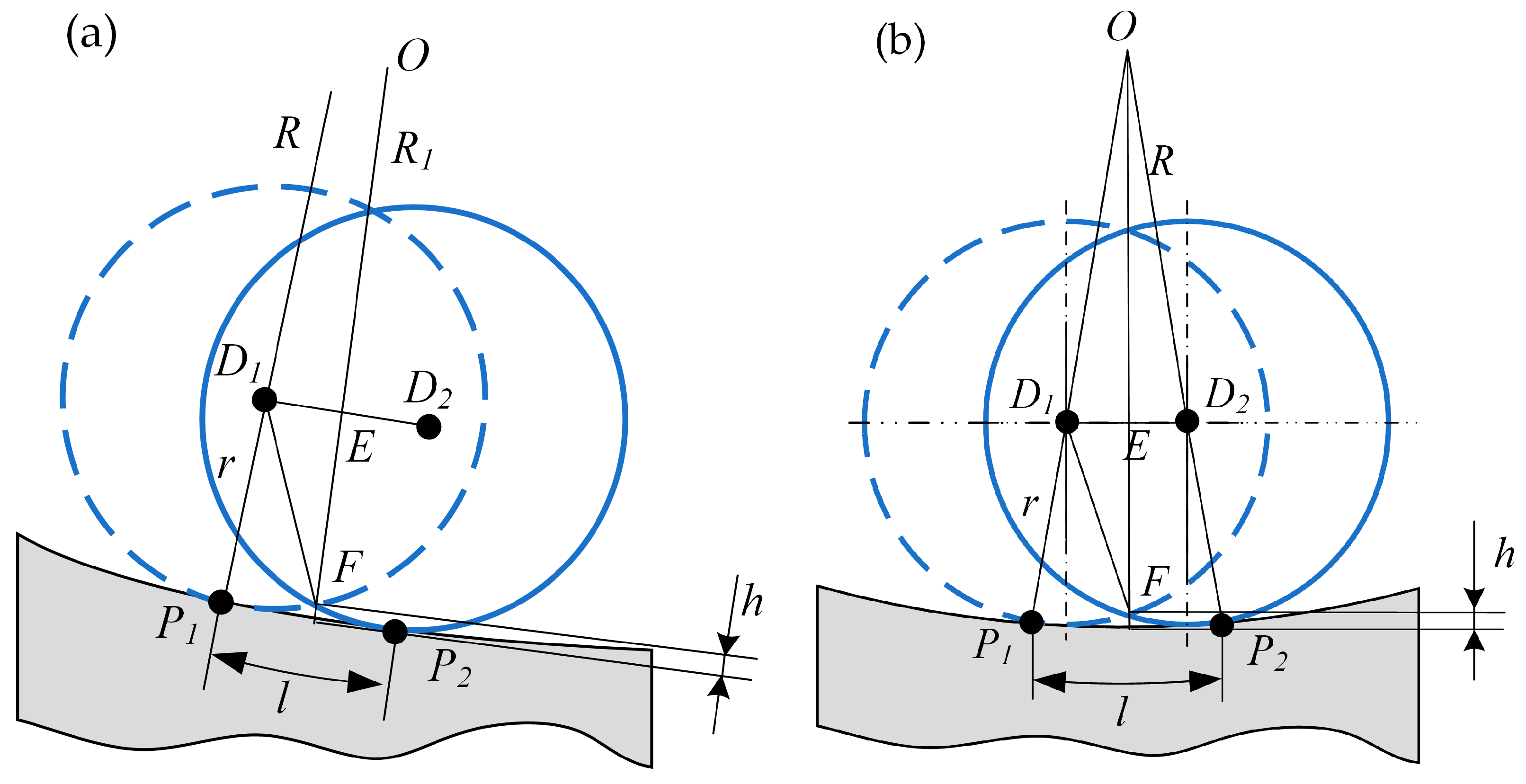
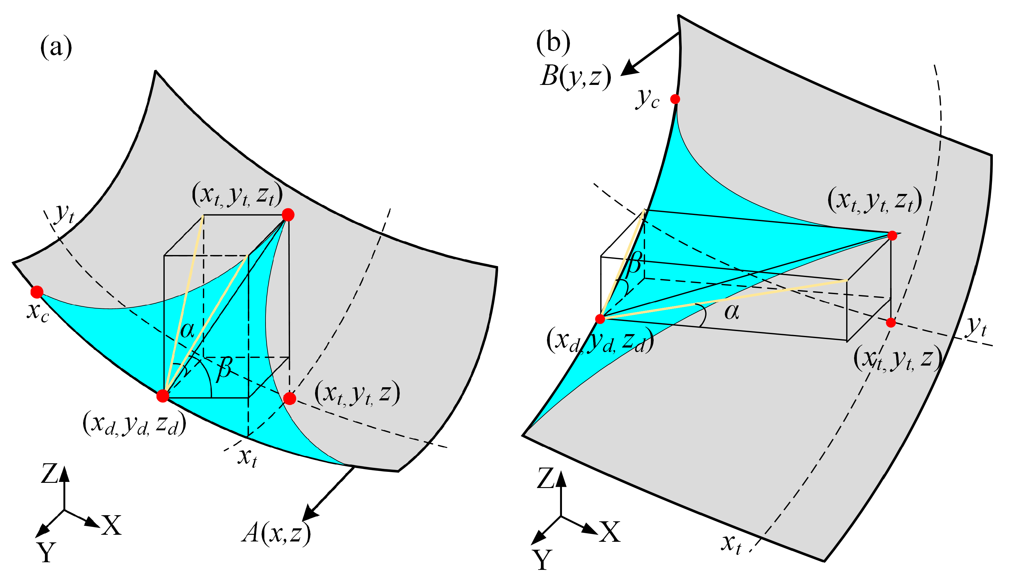
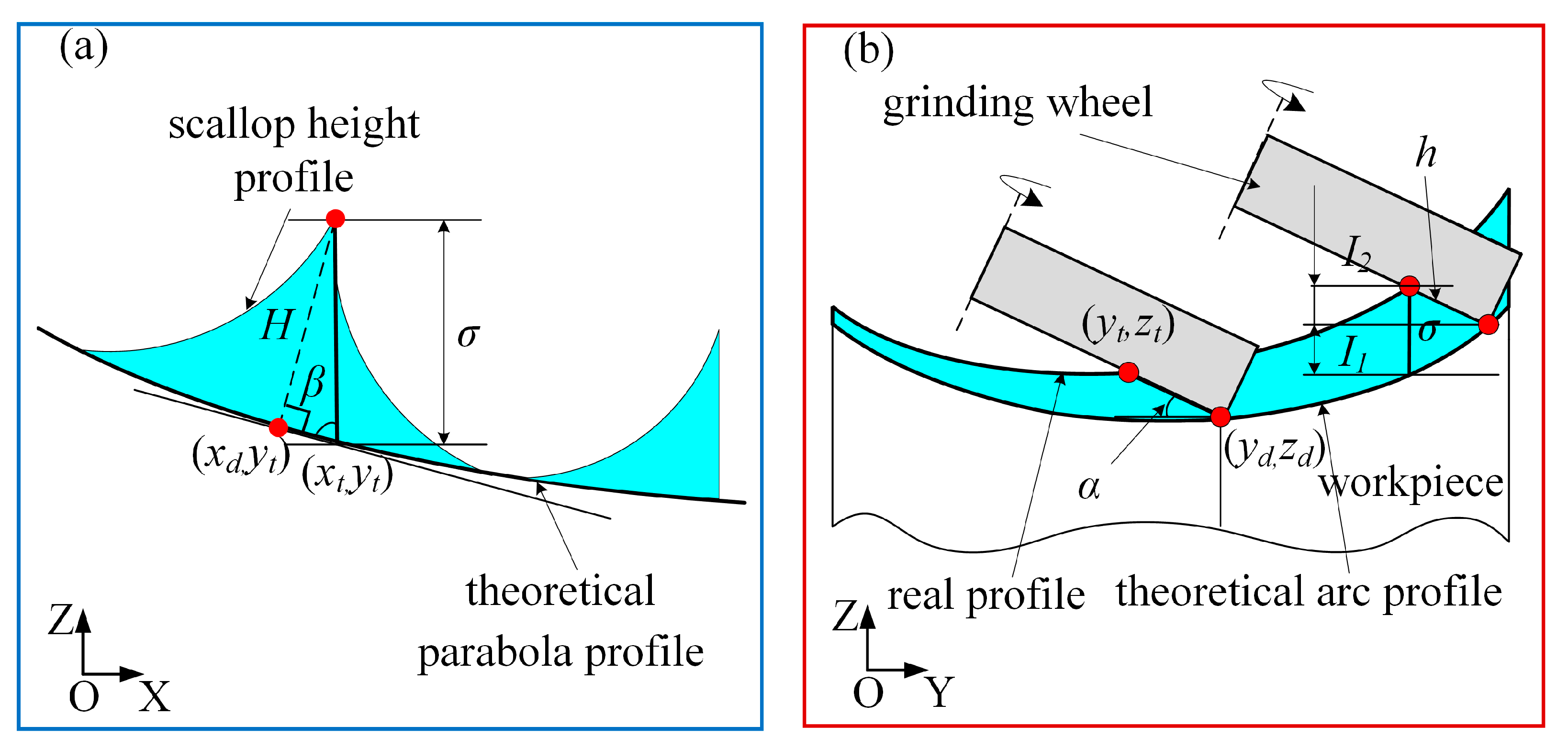
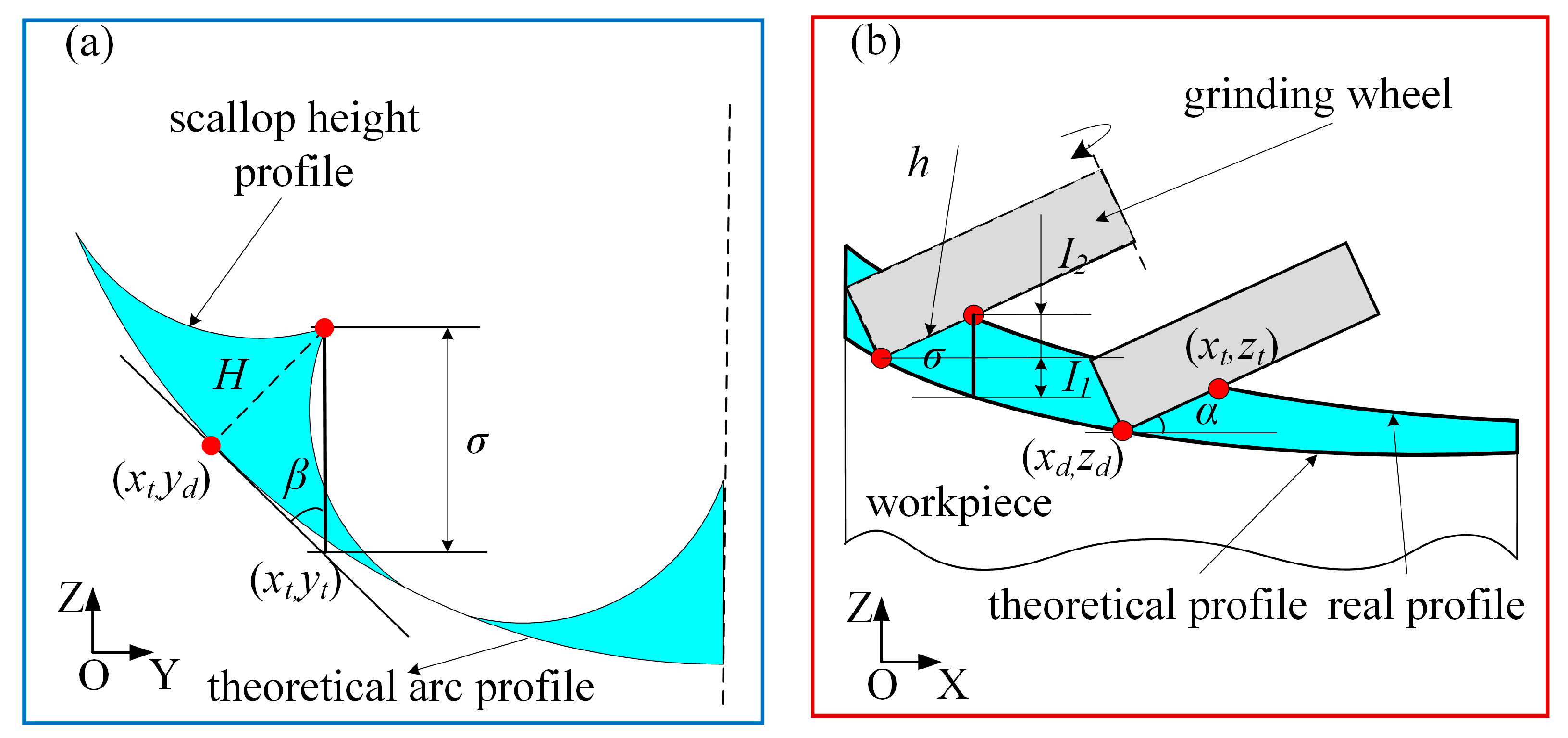
4.1. Modeling Scallop Height of Off-Axis Parabolic Surface
4.2. Analysis of the Factors Affecting the Scallop Height of the Grinding Surface
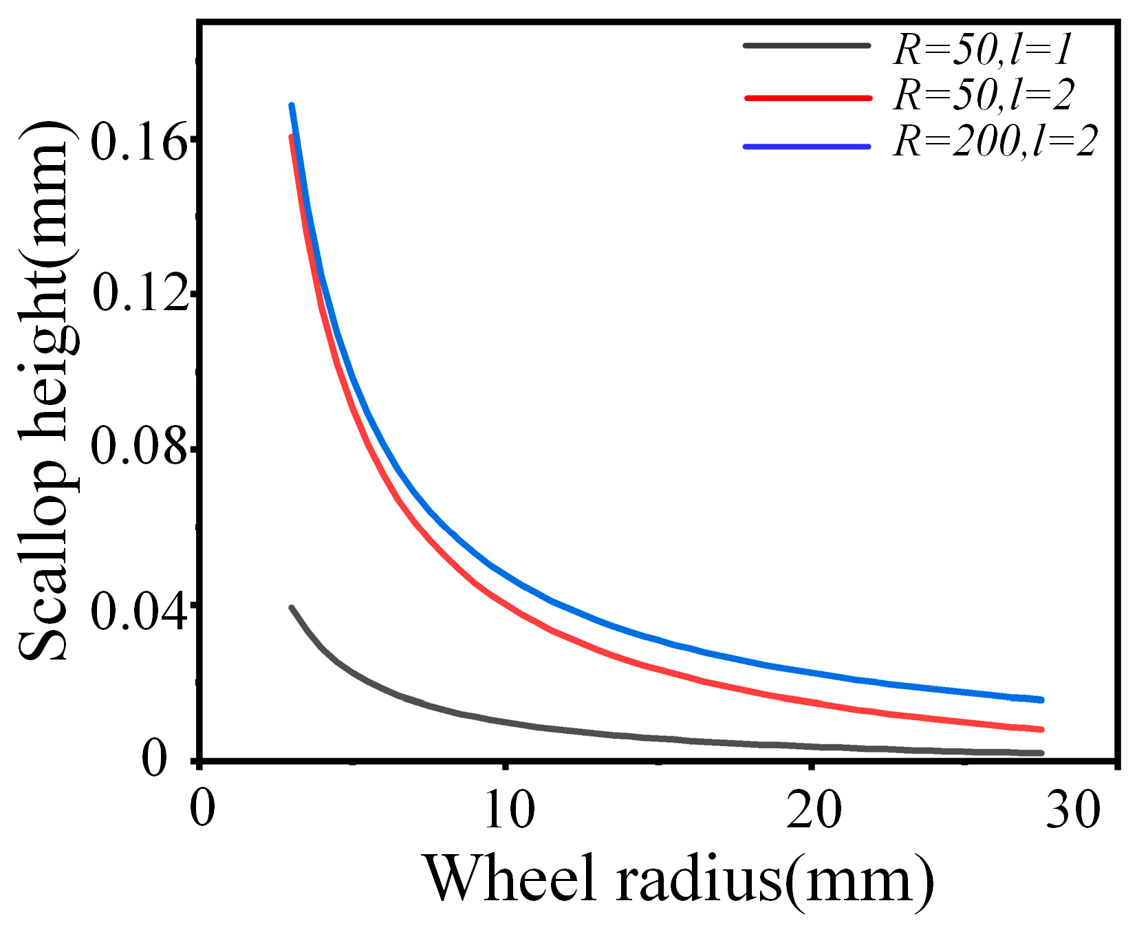
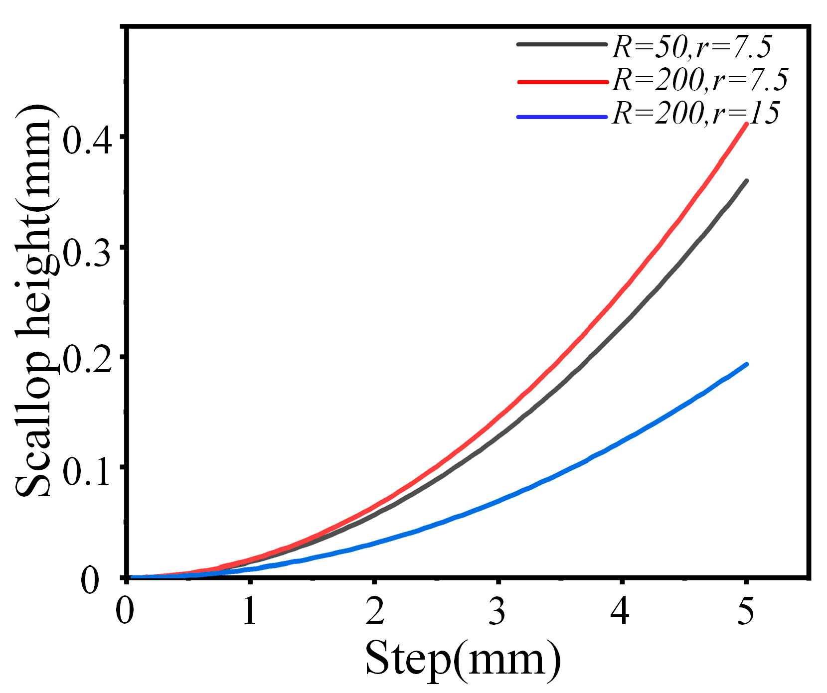
4.2.1. Effect of Grinding Wheel Radius on Scallop Height
4.2.2. Effect of Step Pitch on Scallop Height
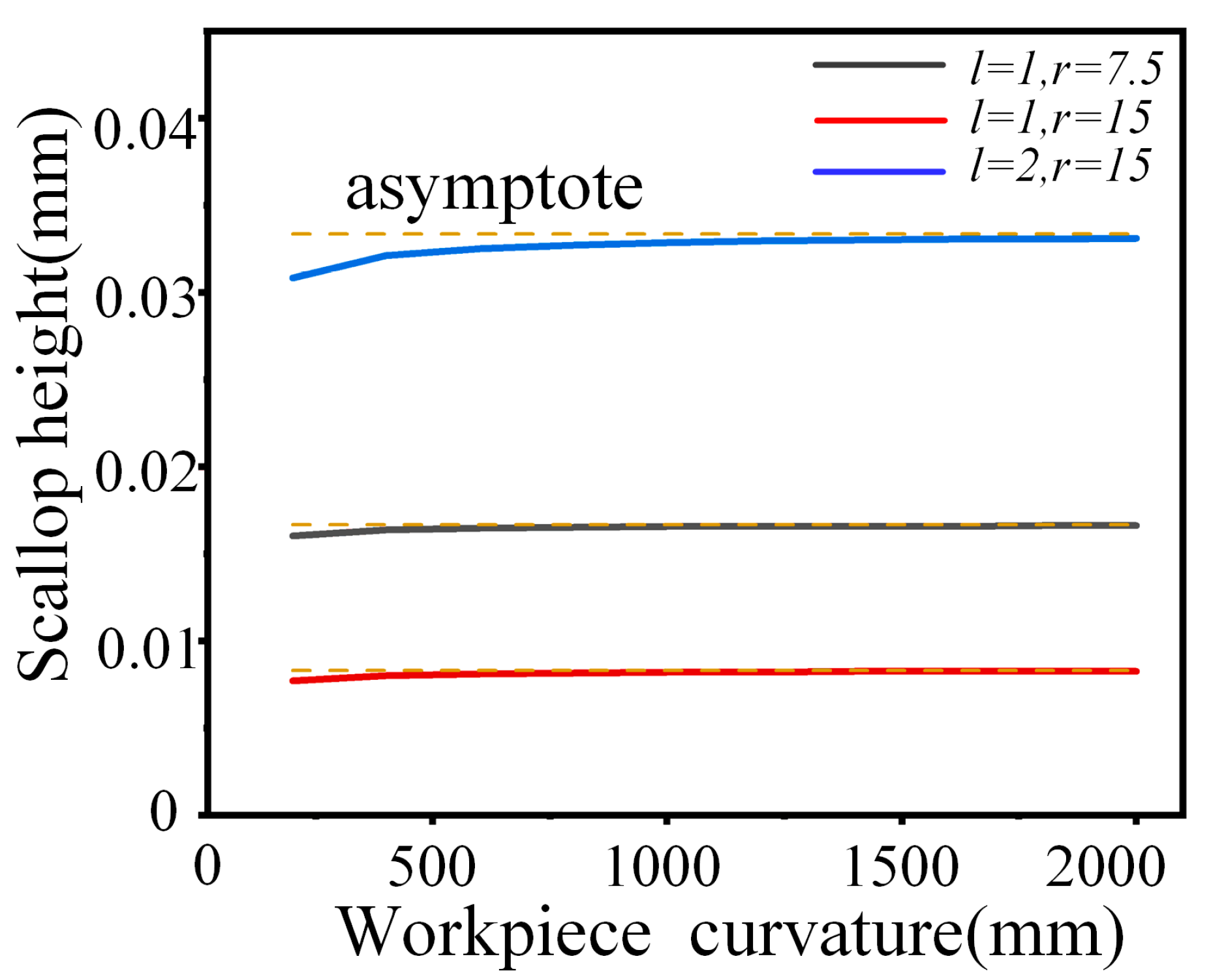
4.2.3. Effect of Workpiece Curvature Radius on Scallop Height
4.3. The Correlation between Scallop Height and Surface Roughness
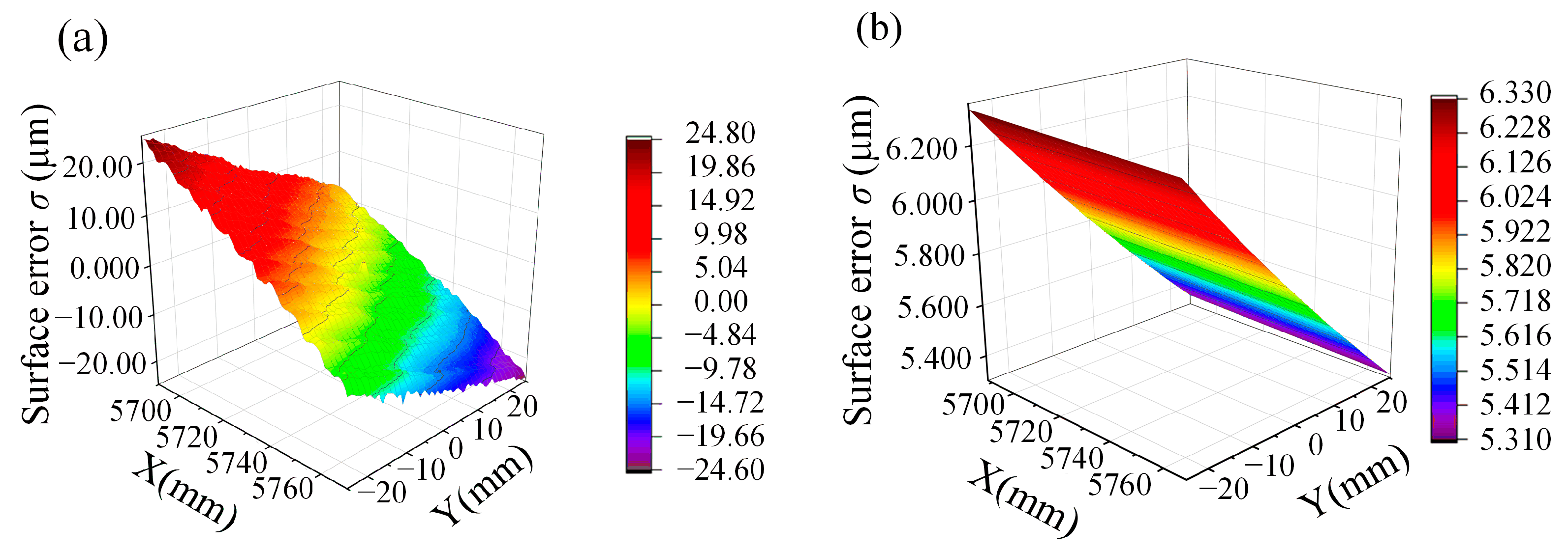
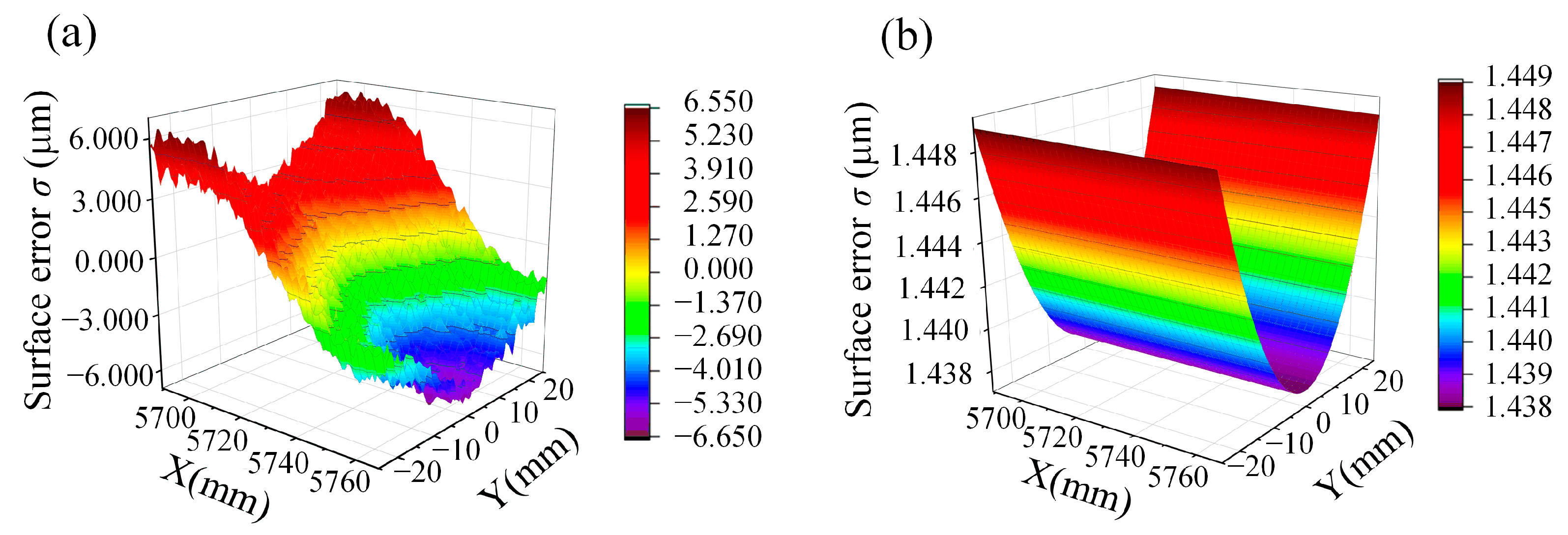
4.4. The Correlation between Scallop Height and Surface Shape Error
4.5. Future Prospects
5. Conclusions
- (1)
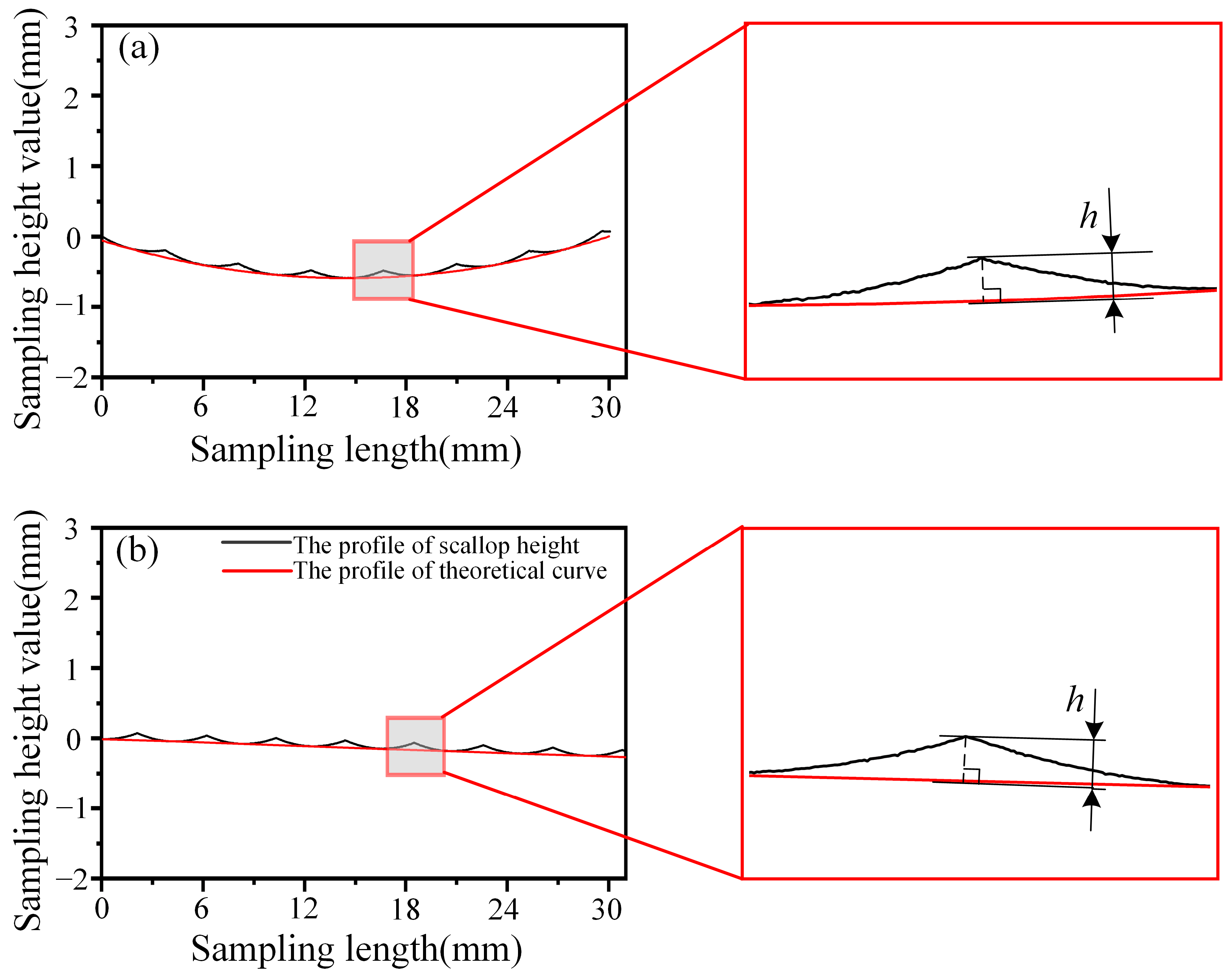
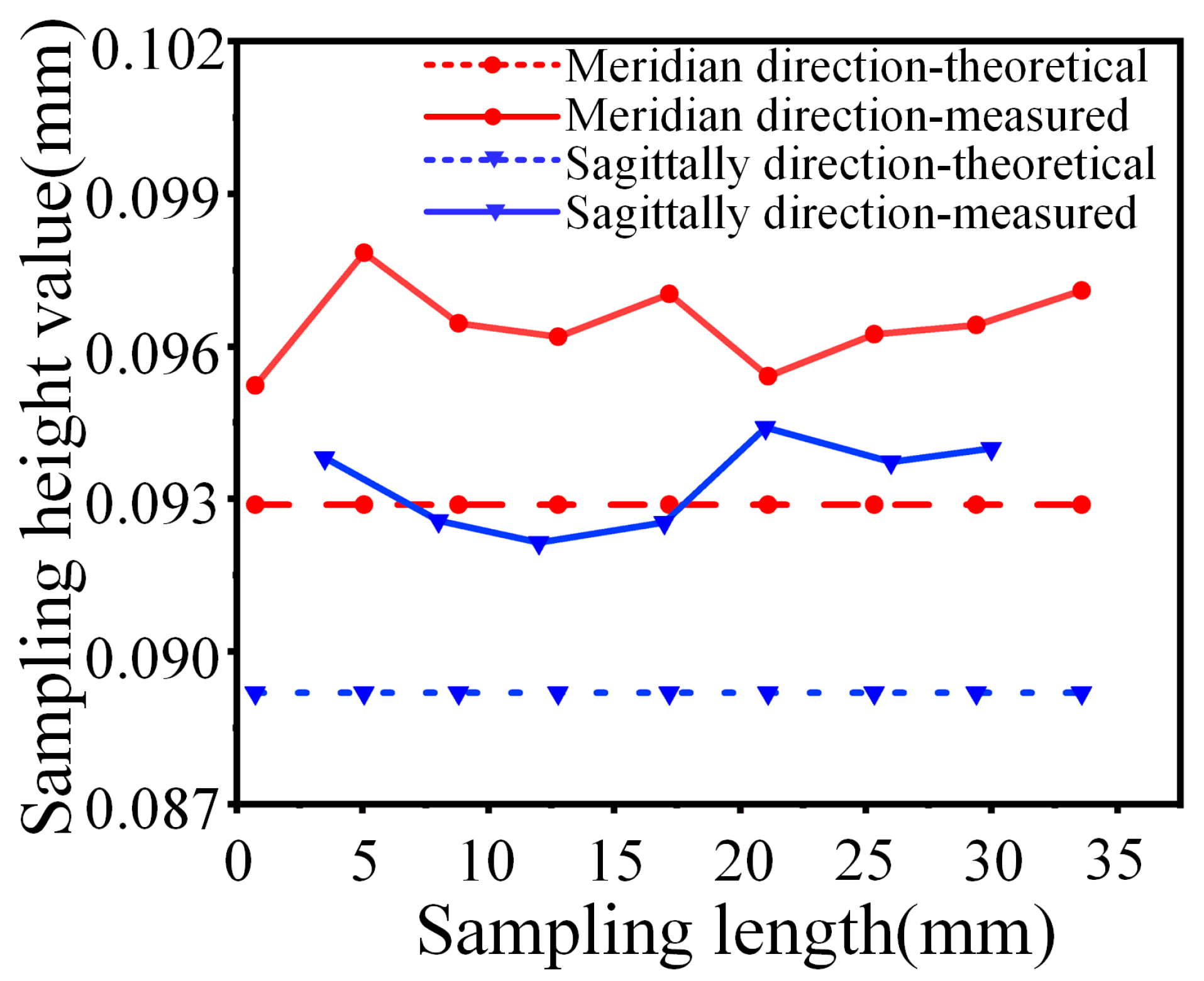
- The scallop height model error was within 5%. It was proven that the model was reasonable and accurate in predicting the scallop height of the off-axis parabolic surface.
- (2)
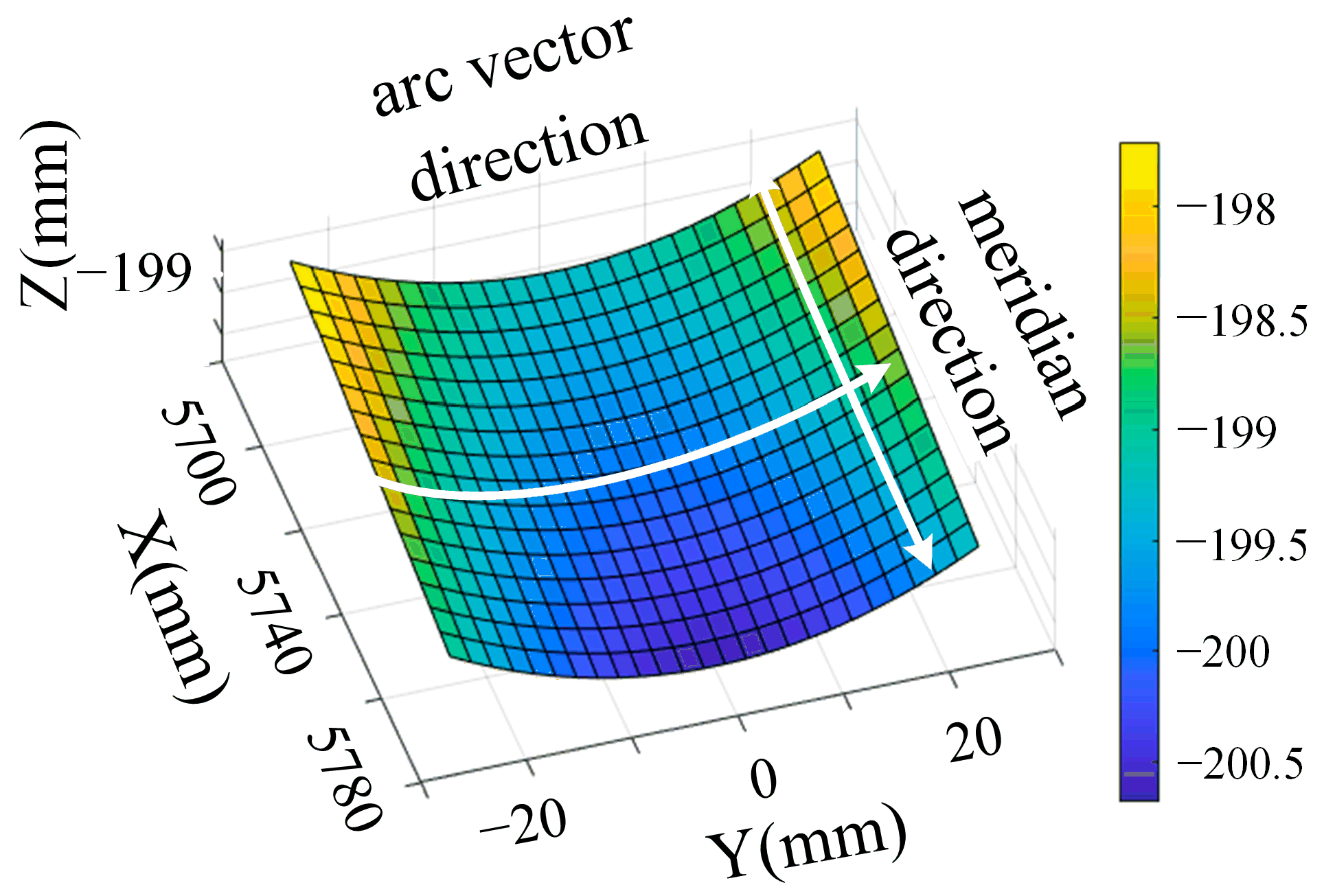
- Upon comparing the scallop height generated by the different raster paths, it was found that the wheel path in raster grinding stepping along the arc vector direction could obtain a smaller scallop height.
- (3)
- Based on the correlation between the scallop height and surface shape error, simulation of the surface shape error distribution was carried out. The simulation results were consistent with the experimental results, which proves the correctness of the simulation.
- (4)
- According to the simulation and experimental results of the surface shape error distribution, it was found that the surface error generated by the step along the arc vector direction was less than that of the raster processing along the meridian direction. In the actual grinding process of an off-axis parabolic surface, the wheel path along the arc vector step is preferred for raster grinding.
Author Contributions
Funding
Institutional Review Board Statement
Informed Consent Statement
Data Availability Statement
Conflicts of Interest
References
- Zhang, W.W.; Allgood, K.D.; Biskach, M.P.; Chan, K.W.; Hlinka, M.; Kearney, J.D.; Mazzarella, J.R.; McClelland, R.S.; Numata, A.; Riveros, R.E.; et al. High-resolution, Lightweight, and Low-cost X-ray Optics for the Lynx Observatory. J. Astron. Telesc. Instrum. Syst. 2019, 5, 021012. [Google Scholar] [CrossRef]
- Chen, L.; Gao, Z.S.; Xu, N.Y.; Cao, X.; Zhang, J.P.; Wang, L.J.; Ye, J.F.; Yuan, Q. Construction of Freeform Mirrors for an Off-axis Telecentric Scanning System through Multiple Surfaces Expansion and Mixing. Results Phys. 2020, 19, 103354. [Google Scholar] [CrossRef]
- Biskch, M.P.; Allgood, K.D.; Chan, K.W.; Hlinka, M.; Kearny, J.D.; Numata, A.; Mazzare, J.R.; Riveros, R.; Saha, T.T.; Solly, P.M.; et al. Mass Manufacturing of High Resolution and Light-weight Monocrystalline Silicon X-ray Mirror Modules. In Proceedings of the Conference on Optics for EUV, X-Ray, and Gamma-Ray Astronomy IX as Part of the SPIE Optics + Photonics International Symposium on Optical Engineering + Applications, San Diego, CA, USA, 13–15 August 2019. [Google Scholar] [CrossRef]
- Qi, J.C.; Ye, L.L.; Chen, R.C.; Xie, H.L.; Ren, Y.Q.; Du, G.H.; Deng, B.; Xiao, T.Q. Coherence of X-ray in the Third Synchrotron Radiation Source. Acta Phys. Sin. 2014, 63, 104202. [Google Scholar] [CrossRef]
- Narayanan, T.; Chevremont, W.; Zinn, T. Small-angle X-ray Scattering in the Era of Fourth-generation Light Sources. J. Appl. Crystallogr. 2023, 56, 939–946. [Google Scholar] [CrossRef] [PubMed]
- Guo, B.; Zhao, Q.L. Wheel Normal Grinding of Hard and Brittle Materials. Int. J. Adv. Manuf. Tech. 2015, 79, 873–880. [Google Scholar] [CrossRef]
- Li, Z.J.; Peng, X.Q.; Song, C. Modeling and Simulation for Fewer-axis Grinding of Complex Surface. In Proceedings of the Annual Conference of the Chinese-Society-for-Optical-Engineering (CSOE) on Applied Optics and Photonics China (AOPC)—Optoelectronics and Micro/Nano-Optics, Beijing, China, 4–6 June 2017. [Google Scholar]
- Yan, Y.Y.; Zhang, Z.Q.; Liu, J.L.; Yan, H.Z.; Wang, X.X. Study on the Algorithm of Three-Dimensional Surface Residual Material Height of Nano-ZrO2 Ceramics under Ultra-Precision Grinding. Micromachines 2021, 12, 1363. [Google Scholar] [CrossRef] [PubMed]
- Wang, S.; Zhang, Q.; Zhao, Q.L.; Guo, B. Surface Generation and Materials Removal Mechanism in Ultra-precision Grinding of Biconical Optics Based on Slow Tool Servo with Diamond Grinding Wheels. J. Manuf. Process. 2021, 72, 1–14. [Google Scholar] [CrossRef]
- Wang, Z.G.; Kang, R.K.; Zhou, P.; Gao, S.; Dong, Z.G. Ultra-precision Grinding of Monocrystalline Silicon Reflector. Opt. Precis. Eng. 2019, 27, 1087–1095. [Google Scholar] [CrossRef]
- Shimizu, Y.; Goto, S.; Lee, J.; Ito, S.; Gao, W.; Adachi, S.; Omiya, K.; Sato, H.; Hisada, T.; Saito, Y.; et al. Fabrication of Large-size SiC Mirror with Precision Aspheric Profile for Artificial Satellite. Precis. Eng. J. Int. Soc. Precis. Eng. Nanotechnol. 2013, 37, 640–649. [Google Scholar] [CrossRef]
- Yuan, J.L.; Yu, B.H.; Hang, W.; Deng, Q.F. Review on the Progress of Ultra-precision Machining Technologies. Front. Mech. Eng. 2017, 12, 158–180. [Google Scholar] [CrossRef]
- Yan, G.P.; Fang, F.Z. Fabrication of Optical Freeform Molds Using Slow Tool Servo with Wheel Normal Grinding. CIRP Ann-Manuf. Technol. 2019, 68, 341–344. [Google Scholar] [CrossRef]
- Deng, H.; Xu, Z. Dressing Methods of Superabrasive Grinding Wheels: A review. J. Manuf. Process. 2019, 45, 46–69. [Google Scholar] [CrossRef]
- Yin, Z.Q.; Dai, Y.F.; Li, S.Y.; Guan, C.L.; Tie, G.P. Fabrication of Off-axis Aspheric Surfaces Using a Slow Tool Servo. Int. J. Mach. Tool. Manu. 2011, 51, 404–410. [Google Scholar] [CrossRef]
- Wang, S.; Zhao, Q.L.; Guo, B. Ultra-precision Ductile Grinding of Off-Axis Biconical Free-Form Optics with a Controllable Scallop Height Based on Slow Tool Servo with Diamond Grinding Wheels. Int. J. Precis. Eng. Manuf. Green. Technol. 2023, 10, 1169–1188. [Google Scholar] [CrossRef]
- Chen, B.; Guo, B.; Zhao, Q.L. An Investigation into Parallel and Cross Grinding of Aspheric Surface on Monocrystal Silicon. Int. J. Adv. Manuf. Tech. 2015, 80, 737–746. [Google Scholar] [CrossRef]
- Wang, S.; Zhao, Q.L.; Guo, B.; Pan, Y.C. Ultra-precision raster grinding of monocrystalline silicon biconical free-form optics using arc-shaped diamond grinding wheels. J. Manuf. Process. 2020, 58, 1064–1074. [Google Scholar] [CrossRef]
- Zhou, L.; Wei, Q.C.; Zheng, N.; Chen, X.H.; Zhang, Q.H.; Wang, J. Dressing Technology of Arc Diamond Wheel by Roll Abrading in Aspheric Parallel Grinding. Int. J. Adv. Manuf. Technol. 2019, 105, 2699–2706. [Google Scholar] [CrossRef]
- Radzevich, S.P. A Closed-form Solution to the Problem of Optimal Tool-path Generation for Sculptured Surface Machining on Multi-axis NC Machine. Math. Comput. Model. 2006, 43, 222–243. [Google Scholar] [CrossRef]
- Xi, J.P.; Zhang, L.B.; Yang, Q.; Li, B.; Zhao, Z.X.; Zhang, C. Nonuniform Rational Basis Spline Interpolation for Off-Axis Aspheric Mirror Grinding Based on Wheel Path Planning. Math. Probl. Eng. 2021, 2021, 6640299. [Google Scholar] [CrossRef]
- Huang, H.; Chen, W.K.; Kuriyagawa, T. Profile Error Compensation Approaches for Parallel Nanogrinding of Aspherical Mould Inserts. Int. J. Mach. Tools Manuf. 2007, 47, 2237–2245. [Google Scholar] [CrossRef]
- Chen, S.S.; Cheung, C.F.; Zhang, F.H.; Liu, M.Y. Optimization of Tool Path for Uniform Scallop-Height in Ultra-precision Grinding of Free-form Surfaces. Nanomanufacturing Metrol. 2019, 2, 215–224. [Google Scholar] [CrossRef]
- Deng, Z.H.; Wan, L.L.; Zhang, X.H.; Li, S.C. Modelling the Processing Parameters of Rotary Curved Surface Grinding Using RSM. Adv. Mater. Res. 2011, 338, 130–135. [Google Scholar] [CrossRef]
- Yu, S.M.; Yao, P.; Ye, Z.; Wang, W.; Chu, D.K.; Qu, S.S.; Huang, C.Z. Simulation and Experimental Research of Tool Path Planning on Profile and Surface Generation of Aspherical-cylindrical Lens Array by Ultra-precision Envelope Grinding. J. Mater. Process Tech. 2022, 307, 117690. [Google Scholar] [CrossRef]
- Jiang, X.; Scott, P.; Whitehouse, D. Freeform Surface Characterisation—A Fresh Strategy. CIRP Ann. Manuf. Technol. 2007, 56, 553–556. [Google Scholar] [CrossRef]
- Jiang, C.; Guo, Y.B.; Li, H.L. Parallel Grinding Error for a Noncoaxial Nonaxisymmetric Aspheric Lens Using a Fixture with Adjustable Gradient. Int. J. Adv. Manuf. Technol. 2013, 66, 537–545. [Google Scholar] [CrossRef]
- Gong, H.G.; Ao, S.J.; Huang, K.T.; Wang, Y.; Yan, C. Tool Path Generation of Ultra-precision Diamond Turning: A State-of-the-art Review. Nanotechnol. Precis. Eng. 2019, 2, 118–124. [Google Scholar] [CrossRef]
- de Souza, A.F.; Kasemodel, R.B.; Arias, M.; Marin, F.; Rodrigues, A.R. Study of Tool Paths Calculated by Different Commercial CAM Systems and Influences on the Real Machining Time and Surface Roughness for Milling Free-form Geometries. J. Braz. Soc. Mech. Sci. Eng. 2019, 41, 12. [Google Scholar] [CrossRef]
- Chen, B.; Li, S.C.; Deng, Z.H.; Guo, B.; Zhao, Q.L. Grinding Marks on Ultra-Precision Grinding Spherical and Aspheric Surfaces. Int. J. Precis. Eng. Manuf. Green. Technol. 2017, 4, 419–429. [Google Scholar] [CrossRef]
- Chen, F.J.; Yin, S.H.; Ohmori, H.; Yu, J.W. Form Error Compensation in Single-point Inclined Axis Nanogrinding for Small Aspheric Insert. Int. J. Adv. Manuf. Technol. 2013, 65, 433–441. [Google Scholar] [CrossRef]
- Kukreja, A.; Pande, S.S. Estimation of Scallop Height in Freeform Surface CNC Machining. Int. J. Adv. Manuf. Technol. 2019, 104, 4231–4242. [Google Scholar] [CrossRef]
- Lv, Z.K.; Su, Z.K.; Zhang, D.; Yang, Z.M.; Yang, X.H.; Wei, X.; Li, J.; Fang, F.Z.; Zhang, H.; Li, X. Displacement Measurement Method Based on the Rotating Paraboloid Array. Appl. Sci. 2019, 9, 3315. [Google Scholar] [CrossRef]
- Li, X.H.; Li, J.; Wei, X.; Yang, X.H.; Su, Z.K.; Liang, J.Q.; Yang, Z.M.; Fang, F.Z. A Noncontact Method for Calibrating the Angle and Position of the Composite Module Array. Appl. Sci. 2020, 10, 4358. [Google Scholar] [CrossRef]
- Deng, Y.H.; Hou, X.; Li, B.C.; Wang, J.; Zhang, Y. Review on Mid-spatial Frequency Error Suppression in Optical Components Manufacturing. Int. J. Adv. Manuf. Tech. 2023, 126, 4827–4847. [Google Scholar] [CrossRef]
- Yin, T.F.; Du, H.H.; Zhang, G.Q.; Hang, W.; To, S. Theoretical and Experimental Investigation into the Formation Mechanism of Surface Waviness in Ultra-precision Grinding. Tribol. Int. 2023, 180, 108269. [Google Scholar] [CrossRef]
- De Groot, P.J. A Review of Selected Topics in Interferometric Optical Metrology. Rep. Prog. Phys. 2019, 82, 056101. [Google Scholar] [CrossRef]

| Parameters | Rough | Finish |
|---|---|---|
| Mesh number | #200 | #500 |
| Wheel rotation n (r/min) | 8000 | 8000 |
| Feed rate v (mm/min) | 500 | 300 |
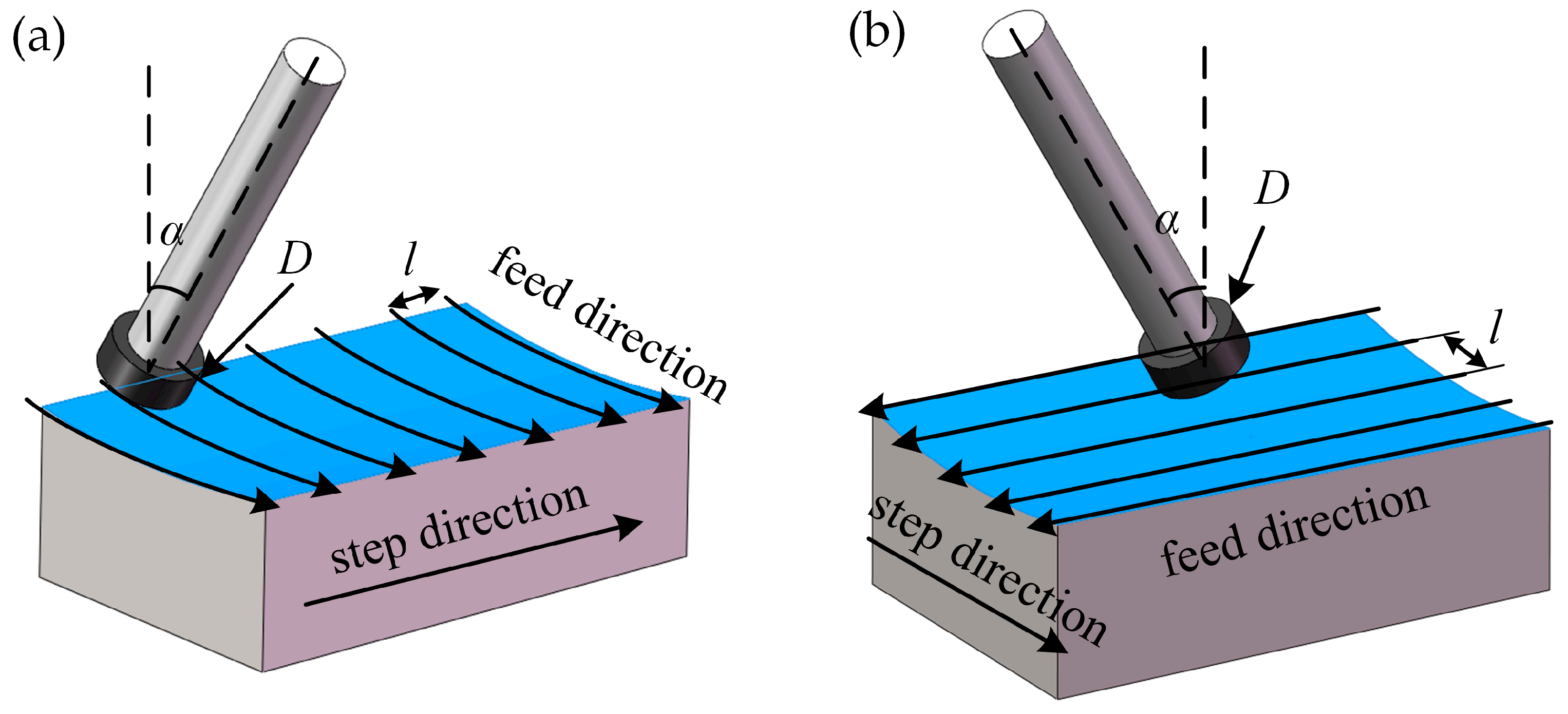
| Wheel diameter D (mm) | 15 | 15 |
| Wheel inclination α (°) | 20 | 20 |
| Step pitch l (mm) | 4 | 0.5 |
Disclaimer/Publisher’s Note: The statements, opinions and data contained in all publications are solely those of the individual author(s) and contributor(s) and not of MDPI and/or the editor(s). MDPI and/or the editor(s) disclaim responsibility for any injury to people or property resulting from any ideas, methods, instructions or products referred to in the content. |
© 2023 by the authors. Licensee MDPI, Basel, Switzerland. This article is an open access article distributed under the terms and conditions of the Creative Commons Attribution (CC BY) license (https://creativecommons.org/licenses/by/4.0/).
Share and Cite
Li, J.; Li, H.; Guo, X.; Kang, R.; Gao, S. Effect of Wheel Path in Raster Grinding on Surface Accuracy of an Off-Axis Parabolic Mirror. Appl. Sci. 2023, 13, 11096. https://doi.org/10.3390/app131911096
Li J, Li H, Guo X, Kang R, Gao S. Effect of Wheel Path in Raster Grinding on Surface Accuracy of an Off-Axis Parabolic Mirror. Applied Sciences. 2023; 13(19):11096. https://doi.org/10.3390/app131911096
Chicago/Turabian StyleLi, Jianhe, Honggang Li, Xiaoguang Guo, Renke Kang, and Shang Gao. 2023. "Effect of Wheel Path in Raster Grinding on Surface Accuracy of an Off-Axis Parabolic Mirror" Applied Sciences 13, no. 19: 11096. https://doi.org/10.3390/app131911096
APA StyleLi, J., Li, H., Guo, X., Kang, R., & Gao, S. (2023). Effect of Wheel Path in Raster Grinding on Surface Accuracy of an Off-Axis Parabolic Mirror. Applied Sciences, 13(19), 11096. https://doi.org/10.3390/app131911096