Article

Tunable Narrow Linewidth External Cavity Diode Laser Employing Wide Interference Filter and Diffraction Grating

1
College of Physics Science and Technology, Shenyang Normal University, Shenyang 110034, China
2
College of Physics and Electronic Engineering, Hainan Normal University, Haikou 571158, China
3
State Key Laboratory of Luminescence and Applications, Changchun Institute of Optics, Fine Mechanics and Physics, Chinese Academy of Sciences, Changchun 130033, China
4
Jlight Semiconductor Technology Co., Ltd., Changchun 130033, China
*
Authors to whom correspondence should be addressed.
Appl. Sci. 2023, 13(19), 10790; https://doi.org/10.3390/app131910790
Submission received: 29 August 2023 / Revised: 22 September 2023 / Accepted: 25 September 2023 / Published: 28 September 2023

Abstract

:

Featured Application

Tunable ultra-narrow linewidth external cavity diode laser can be applied in the field of laser radar, high-dynamic-range measurement, and coherent detection.

Abstract

We design a unique external cavity configuration and present an ultra-narrow linewidth external cavity diode laser (ECDL) employing a wide interference filter and diffraction grating. The interference filter is for suppressing the noise floor, and diffraction grating is used for the mode selection. The combination of the filter and diffraction grating can effectively use a narrow linewidth without a significant reduction in optical gain. The Lorentz linewidth reaches 13.6 kHz at a wavelength of 1555 nm. The ECDL can be tuned by rotating the diffraction grating, and a wide tunable range of 40 nm is achieved with a maximum output power of 25.6 mW at an injection current of 200 mA. In addition, the ECDL shows an excellent side mode suppression ratio (SMSR) performance with a maximum of 57 dB at 1555 nm. Additionally, the SMSR changes gently throughout the tuning range at the injection current of 200 mA.

1. Introduction

Due to the excellent stable emission performance of a wide tunable range and low cost, external cavity diode lasers (ECDLs) have become an ideal lasing source in many fields, such as high-resolution spectroscopy, optical sensing, atomic clocks and gas detection [1,2,3,4]. In particular, the narrow linewidth characteristic of ECDL is the key element for coherent optical communication systems, coherent detection, optical sensing and measurement systems [5], and has attracted an extensive amount of attention.
To achieve a narrow linewidth output, optical elements with the function of mode selection are applied to an external cavity structure, such as the confocal Fabry–Perot cavity, diffraction grating, etalon, and interference filter [6,7]. As the common external cavity structures, Littrow and Littman configurations use diffraction grating for optical feedback and mode selection [8,9,10]. A compact, tunable MEMS ECDL was designed, and a tuning range of about 40 nm in the C-band with a linewidth of less than 50 kHz was achieved [11]. Of course, the grating parameters such as grating reflectivity and grating resolution also have an effect on the tunable range and linewidth [12]. In addition, the interference filter shows a very good performance of wavelength selection [13]. An interference filter with a multimode bandwidth is employed in an external cavity diode laser, and the laser can be tuned over 14 nm with a narrow linewidth of 26 kHz [14]. In addition, the interference filter can be used alone in the external cavity system for the wavelength selection and can reduce the sensitivity of the wavelength [15,16]. Although narrow bandpass filters provide an alternative approach to the wavelength selection, they limit the tuning range of lasers.
In this paper, we design and present a unique tunable external cavity structure. We employ diffraction grating and an interference filter to achieve a narrow linewidth output. The interference filter is placed between the lens and the grating. By adding the filter, the SMSR is improved due to filtering out the fluctuation of the noise floor. The interference filter can suppress the potential competition mode and improve the spectral purity of the main mode. In this way, the linewidth is narrowed. The diffraction grating is for the wavelength selection and optical feedback. Based on the external cavity structure of ECDL, it achieves an ultra-narrow linewidth output of 13.6 kHz. Meanwhile, the ECDL has a wide tunable range of 40 nm at an injection current of 200 mA by adjusting the diffraction grating. During the tuning process, there may be a mode-hopping phenomenon. Additionally, the SMSR throughout the tuning range is measured. The highest SMSR is 57 dB at a wavelength of 1555 nm.

2. Experimental Setup

The experimental setup of the ECDL is given in Figure 1. A commercial single-angled facet (SAF) gain chip (Thorlabs (Newton, NY, USA), SAF1126 heatsink assemble) is chosen to achieve a stable output. The reflectivity of the rear facet (R1) is less than 0.01%, which is ultra-low to ensure that the light feedback level reflects back from the external cavity. Additionally, the reflectivity of another facet (R2) is about 10%. The laser output from the rear facet is collimated by lens 1 (SBJ2.4F1.14-042), passed through the interference filter (Thorlabs, FBH1550-40) and diffracted on a diffractive grating (Thorlabs, GR13-0616, 600 lines/mm). The interference filter has a high transmission of more than 95%, with 40 nm transmittance ranges from 1525 nm to 1565 nm. The diffractive grating is 600 lines/mm, and the first-order diffractive beam of the grating is feedbacked into the gain chip. Finally, the laser is the output from the front facet, collimated by lens 2 (SBJ2.4F1.14-042) and coupled into a fiber. As seen in Figure 1, the beam splitter (BS) is used to measure the optical power, optical spectrum and linewidth.
We employ the delayed self-heterodyne technique to measure the laser linewidth, as shown in Figure 1 [17]. The length difference of two interferometer fiber arms needs to be large enough to ensure its accuracy and sensitivity. The output signal first passes the isolator and coupler 1. Then, it is split. One path passes the delayed single-mode optical fiber of 75 km. Another one is sent to the acousto-optic modulator (AOM). To eliminate the influence of DC noise, AOM shifts the laser frequency by 80 MHz. The two beams go through coupler 2 and are mixed by the detector. In addition, the couplers are single-input double-output types and the split ratio is 1:1 for couplers 1 and 2. We obtain the result on the spectrum analyzer and measure the Lorentz linewidth after fitting.

3. Spectral Linewidth

The theoretical formula for the spectral linewidth of ECDL has been investigated in many papers [18]. Consider an external cavity semiconductor laser comprising a laser diode with cavity length l and an external mirror at a distance L. The linewidth is written in the following formula [19].
ν = ν g 2 h ν n s p a m g 8 π P o u t     1 D r + D 1 r + α 2 β 2 D r
where   ν g is the group velocity, h is the Plank constant. The spontaneous emission factor n s p can be definited by the ratio of the spontaneous emission rate per laser mode to the stimulated emission rate per laser photon. α is the linewidth enhancement factor. The factor β can be calculated from the phase condition for the longitudinal modes of the whole cavity [20]. The D(r) and D1(r) are written as follows:
D r = 1 + r 2 r 1 e 1 1 r 2 r 1 e ln 1 / r 2 2 2 1 r 2 2 ln 1 / r 2 r 1 e
D 1 r = n 1 2 L c 2 n 2 l 1 1 r 2 2 r 1 e r 2 ln 1 / r 2 2
where r1e is the effective reflectivity of the external cavity, r2 is the reflectivity of output surface (R2 as shown in Figure 1), Lc is the coherent length, n is the refractive index of the diode, and n1 is the effective refractive index of the external cavity.
We can achieve a narrow linewidth by controlling the structure and composition of the external cavity. According to the equations, the linewidth can be narrowed effectively by improving the r1e and n1 of the external cavity. Therefore, the reasonable selection of external optical element parameters is very important.

4. Results and Discussion

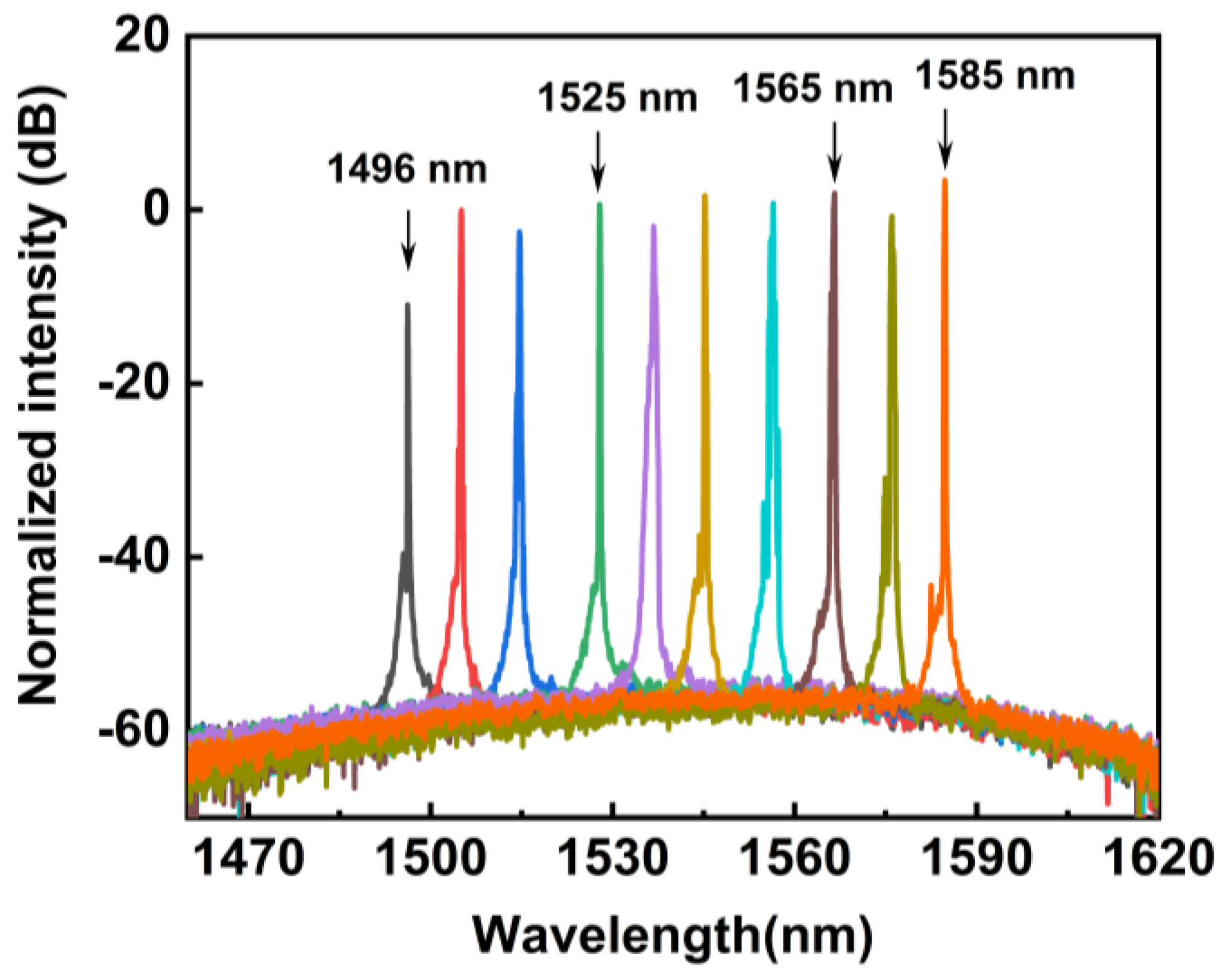
4.1. Tunable Optical Spectra
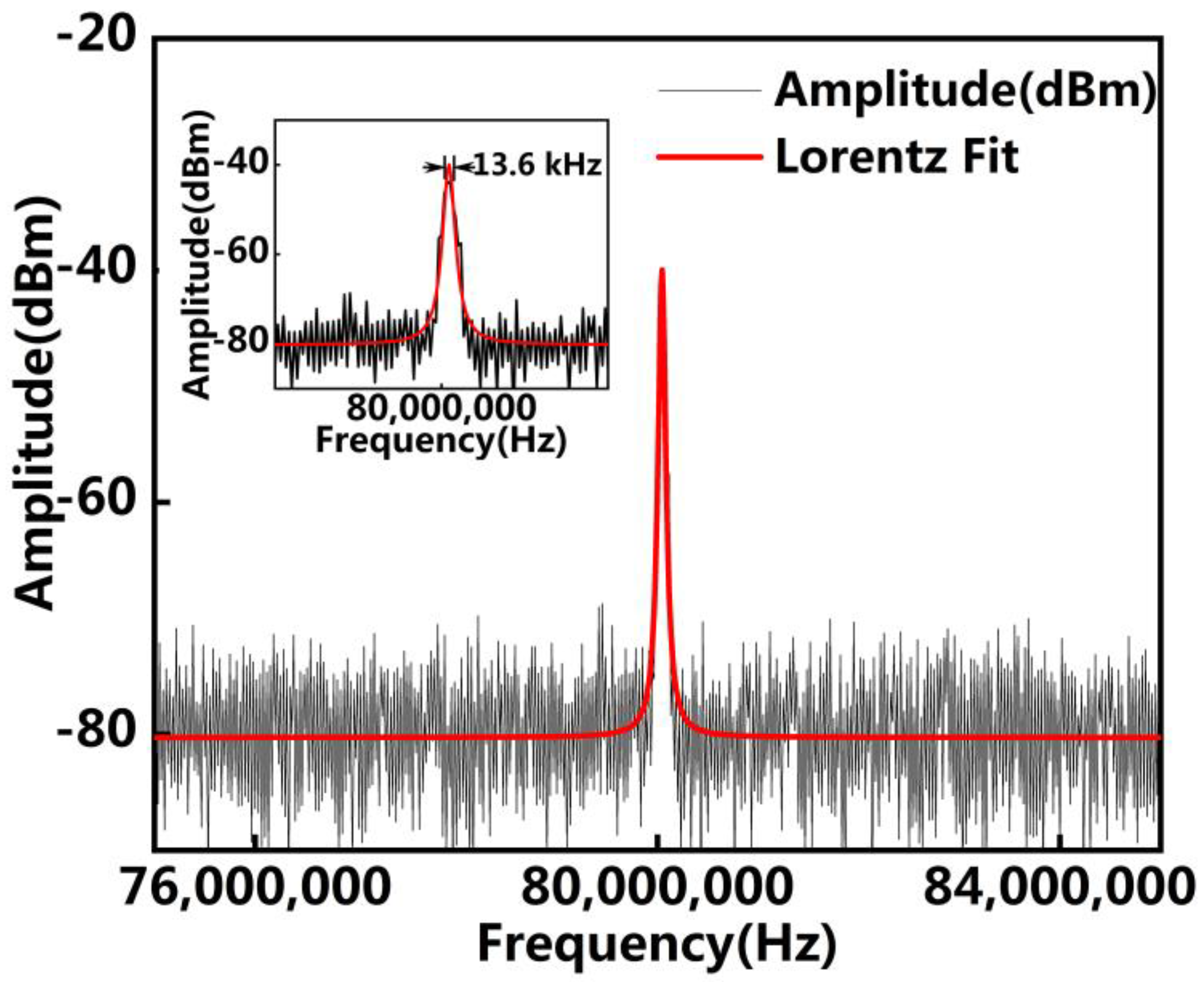
Figure 2 is the optical spectra of the ECDLs, which was measured by an optical spectrum analyzer (OSA, YOKOGAWA, AQ6370D, Tokyo, Japan) with a resolution of 0.02 nm. The injection currents are, respectively, 150 mA and 200 mA for Figure 2a,b. The tunable optical spectra were obtained by adjusting the grating along the vertical direction. As shown in Figure 2, the optical spectra of the ECDL show a wide tunable range and excellent SMSR. It can be seen that the tunable range remains unchanged when the injection current increases from 150 mA to 200 mA. The tunable range is 40 nm from 1525 nm to 1565 nm. During the tuning process, mod hopping may occur. In our experiment, the tunable range is limited by the bandpass of the filter when the gain is relatively high. For the interference filter, the bands outside the passband have very low transmittance. Additionally, the gain of the external cavity laser outside the passband decreases rapidly. As can be seen from the figure, the ECDL has high SMSR during the whole tuning range with an injection current of 200 mA.

4.2. The Linewidth

The linewidth is measured by the delayed self-heterodyne technique. The measured spectrum is the Lorentz line-type. Therefore, the 3 dB bandwith is obtained by fitting the measurement spectrum to the Lorentz curve (the red curve). The 3 dB bandwith represents the spectral width when the maximum value of the spectrum is reduced by 3 dB. The 3 dB linewidth at a wavelength of 1555 nm is measured, as shown in Figure 3, and an ultra-narrow linewidth of 13.6 kHz is obtained.
Combining Formulas (1)–(3), it can be seen that the linewidth is affected by many factors, such as the cavity surface reflectivity and refractivity index of external cavity. In our experiment, the external cavity structure includes two optical components, diffraction grating and interference filter. Both diffraction grating and the interference filter play a very important role in narrowing the linewidth. First, for the external cavity configuration, the effective reflectivity r1e depends on the reflectivity of the rear facet (R1) and the diffraction efficiency of the grating. Therefore, a rear facet with reflectivity less than 0.01% and diffraction grating with a diffraction efficiency of 90% are chosen to achieve large, effective reflectivity to narrow the linewidth. Second, the interference filter contributes to narrowing the linewidth. The filter is composed of alternating layers of dielectric materials, in which multiple reflections can be realized. We measured the optical spectra without the filter, as shown in Figure 4. We compared the SMSR before and after adding the filter; the specific results are shown in Table 1. It can be seen that the SMSR of the ECDL with a filter is improved because the interference filter can filter out the fluctuation of the noise floor. In this way, the filter can reduce the potential competition mode, improve the spectral purity of the main mode, and further narrow the linewidth.
In the whole tuning range, the gain is relatively high at an injection current of 200 mA. The linewidth does not change obviously when the wavelength changes. In addition, according to the formula, the calculated linewidth can be optimized by improving the effective refractive index of the external cavity. In our experiment, the effective reflection of the external cavity is a function of the diffraction efficiency of the grating and the transmission of the filter. Therefore, the linewidth can be further narrowed by optimizing the dielectric film structure of the interference filter.

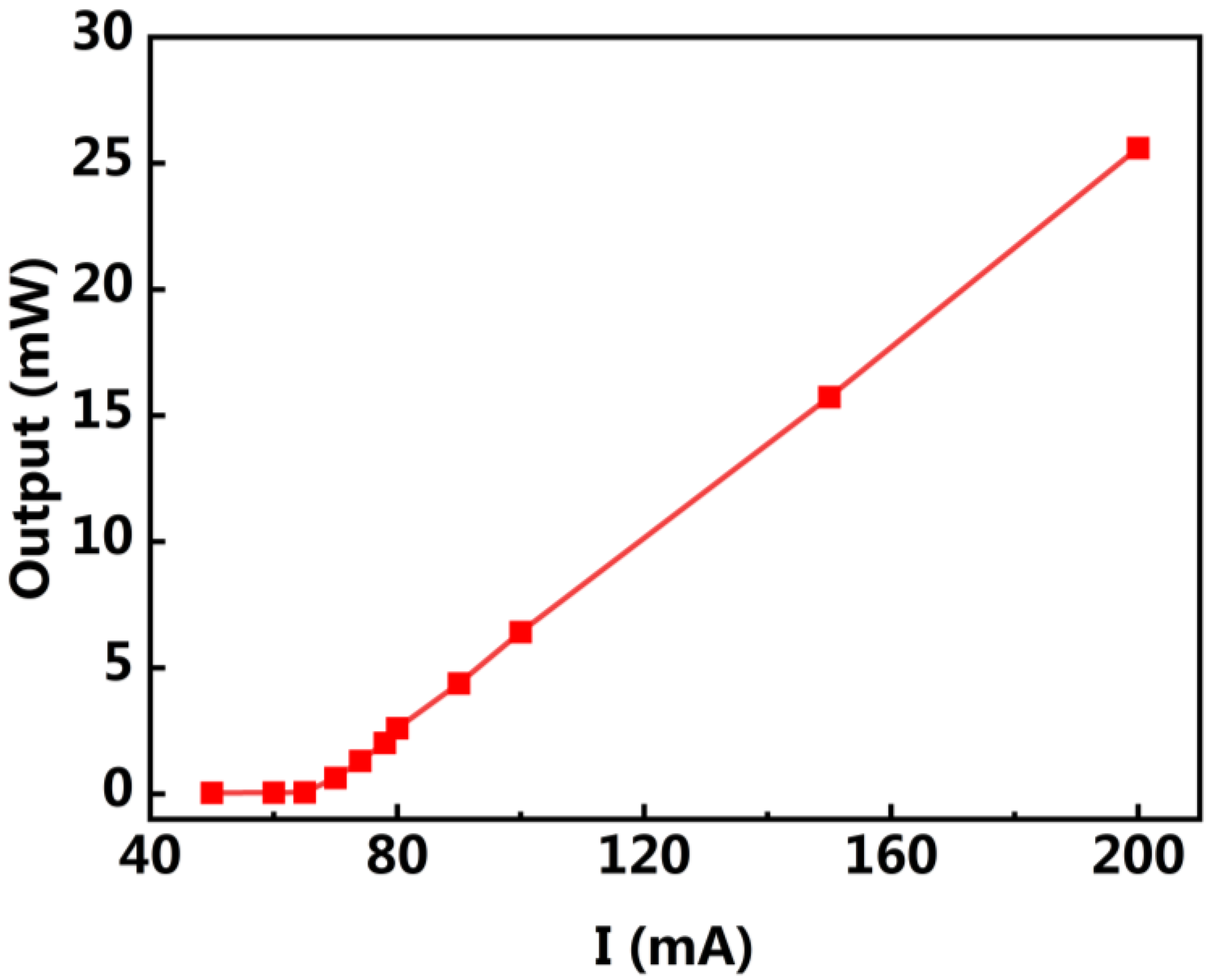
4.3. The Threshold Current

To further characterize the performance of the ECDL, the variation in the output power with the current is measured at a wavelength of 1550 nm, as shown in Figure 5. As can be seen from the picture, the threshold current of the ECDL is 68 mA. Due to the ultra-low reflectivity of the rear facet (R1, 0.01%), the ECDL has a relatively low threshold current. The slope efficiency is about 0.19 W/A. Additionally, an output power of 25.6 mW is obtained with an injection current of 200 mA.

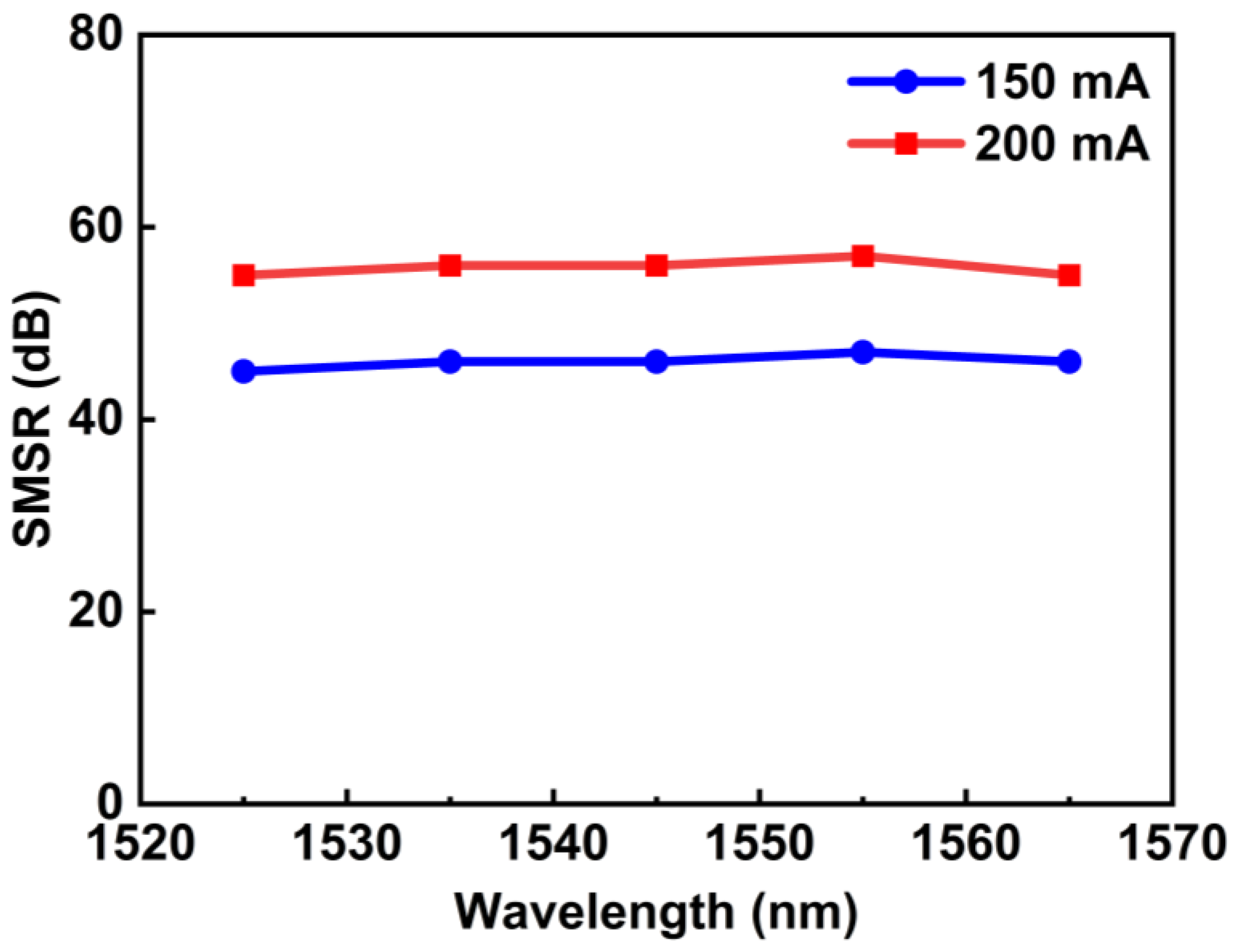
4.4. The Side Mode Suppression Ratio

To characterize the relationship between the SMSR and injection current, the SMSRs of the ECDL system at a function of different wavelengths are measured at injection currents of 150 nm and 200 nm, respectively. The statistical result is illustrated in Figure 6. It can be seen from Figure 6 that the tunable range is basically unchanged as the current increases. This is because the bandwidth of interference filter is 40 nm. Additionally, under the low current condition of 150 mA, it still has a relatively high gain in the tunable band of 1525 nm to 1565 nm. As shown in Figure 6, the SMSR is increased significantly when the injection current increases from 150 mA to 200 mA. The maximum SMSR is 47 dB at an injection current of 150 mA. Additionally, the maximum SMSR reaches 57 dB at the wavelength of 1555 nm with an injection current of 200 mA. Furthermore, the gain of the external cavity laser within the passband of interference is relatively high when the injection current is higher than 150 mA, and the SMSR changes gently throughout the tuning range when the injection current is higher than 150 mA.

4.5. The Output Power

The power of ECDL can be described by the function [11]:
P o u t = ν g 2 h ν ω ν a m S 2 R S P
with the threshold loss of the laser a m
a m = 1 l ln 1 / r 1 r e f f + a i n
where h is the Planck constant, ν is the frequency. S is the number of photons in the gain medium. a i n is the intracavity loss-of-gain medium, r 1 is the absorption coefficient of the diode cavity and r e f f is the effective reflection of the external cavity.
The output power is dependent on the combined result of optical gain and intra-cavity loss. On the one hand, optical gain and loss are related to the structure of the gain chip. On the other hand, from Formulas (4) and (5), they are related to the efficiency of optical elements in the external cavity. In our experiment, a relatively high output power is obtained. The output power is measured as a function of wavelength under an injection current of 200 mA, as shown in Figure 7. Over the tunable range of wavelength, the optical gain is different for different output wavelengths. Therefore, the power varies with wavelength. As shown in Figure 7, the power in the middle part is higher and the power on both sides is lower. The maximum output power is 25.6 mW at a wavelength of 1550 nm. The gain loss of the wide bandpass filter is relatively small, and it has high output power at a low current condition. If the injection current is enhanced, it would obtain higher output power.

5. Conclusions

In this paper, an ECDL configuration with a wide interference filter and diffraction grating is characterized. Additionally, we analyzed and tested the laser performance. The experiment result shows that the external cavity structure has a good compression linewidth characteristic. The Lorenz linewidth at a wavelength of 1555 nm is 13.6 kHz. Additionally, we attribute it to the suppression of the noise floor by the interference filter and the mode selection of high reflectivity diffraction grating. In addition, the optical performance of the ECDL is tested at an injection current of 200 mA. The ECDL has a wide tunable range of 40 nm from 15,250 nm to 1565 nm and a high SMSR of 57 dB at a wavelength of 1555 nm. Additionally, an output power of 25.6 mW is achieved.

6. Patents

Based on the research result of this manuscript, we have applied for a patent.

Author Contributions

Methodology: Y.W. (Yan Wang), H.W. and L.Q.; data: experimental operation: T.Z., K.D. and Q.C.; data analysis: Y.W. (Yan Wang), K.D., Y.L., T.Z., Y.W. (Yanyan Wu) and Y.C.; writing: Y.W. (Yan Wang); review and editing: H.W. and Y.W. (Yan Wang). All authors have read and agreed to the published version of the manuscript.

Funding

This research was funded by National Natural Science Foundation of China, grant number 62004132, 62004194, 62090051; the Doctoral Research Project of Shenyang Normal University, grant number BS202026, BS202131; National Science and Technology Major Project of China, grant number 2022YFB2803500.

Institutional Review Board Statement

Not applicable.

Informed Consent Statement

Not applicable.

Data Availability Statement

Not applicable.

Conflicts of Interest

The authors declare no conflict of interest.

References

  1. Galbacs, G. A review of applications and experimental improvements related to diode laser atomic spectroscopy. Appl. Spectrosc. Rev. 2006, 41, 253–303. [Google Scholar] [CrossRef]
  2. Affolderbach, C.; Mileti, G. A compact laser head with high-frequency stability for Rb atomic clocks and optical instrumentation. Rev. Sci. Instrum. 2005, 76, 073108. [Google Scholar] [CrossRef]
  3. Laurila, T.; Cattaneo, H.; Koskinen, V.; Kauppinen, J.; Hernberg, R. Diode laser-based photoacoustic spectroscopy with interferometrically-enhanced cantilever detection. Opt. Express. 2005, 13, 2453–2458. [Google Scholar] [CrossRef]
  4. Kielinski, D.; Cetina, M.; Cox, J.A.; Kärtner, F.X. Laser cooling of trapped ytterbium ions with an ultraviolet diode laser. Opt. Lett. 2006, 31, 757–759. [Google Scholar] [CrossRef]
  5. Hang, G.; Ari, N.; Tal, G.; Yang, J.; Saeed, F.; Alexandre, H.; Tam, N.; Jose, R.; Shi, R.; Michael, C.; et al. Widely-tunable, narrow-linewidth III-V/silicon hybrid external-cavity laser for coherent communication. Opt. Express 2018, 26, 7920. [Google Scholar]
  6. Lewoczko-Adamczyk, W.; Pyrlik, C.; Häger, J.; Schwertfeger, S.; Wicht, A.; Peters, A.; Erbert, G.; Tränkle, G. Ultra-narrow linewidth DFB-laser with optical feedback from a monolithic confocal Fabry-Perot cavity. Opt. Express 2015, 23, 9705–9709. [Google Scholar] [CrossRef] [PubMed]
  7. Wang, Y.; Wu, H.; Chen, C.; Zhou, Y.; Wang, Y.; Liang, L.; Tian, Z.; Qin, L.; Wang, L. An Ultra-High-SMSR External-Cavity Diode Laser with a Wide Tunable Range around 1550 nm. Appl. Sci. 2019, 9, 4390. [Google Scholar] [CrossRef]
  8. Biebersdorf, A.; Lingk, C.; Giorgi, M.; Feldmann, J.; Sacher, J.; Arzberger, M.; Ulbrich, C.; Bohm, G.; Amann, M.; Abstreiter, G. Tunable single and dual mode operation of an external cavity quantum-dot injection laser. J. Phys. D 2003, 36, 1928–1930. [Google Scholar] [CrossRef]
  9. Saliba, S.; Scholten, E. Linewidths below 100 kHz with external cavity diode lasers. Appl. Opt. 2009, 48, 6961–6966. [Google Scholar] [CrossRef]
  10. Chi, M.; Jensen, O.; Petersen, P. High-power dual-wavelength external-cavity diode laser based on tapered amplifier with tunable terahertz frequency difference. Opt. Lett. 2011, 36, 2626–2628. [Google Scholar] [CrossRef] [PubMed]
  11. Zhang, D.; Zhao, J.; Yang, Q.; Liu, W.; Wang, L. Compact MEMS external cavity tunable laser with ultra-narrow linewidth for coherent detection. Opt. Express 2012, 20, 19670–19682. [Google Scholar] [CrossRef] [PubMed]
  12. Loh, H.; Lin, Y.J.; Teper, I.; Cetina, M.; Simon, J.; Thompson, J.K.; Vuletić, V. Influence of grating parameters on the linewidths of external-cavity diode lasers. Appl. Opt. 2006, 45, 9191–9197. [Google Scholar] [CrossRef] [PubMed]
  13. Alexander, M.; Patrick, B.; Gerhard, B. External cavity diode laser setup with two interference filters. Appl. Phys. B 2016, 122, 298. [Google Scholar]
  14. Thompson, D.J.; Scholten, R.E. Narrow linewidth tunable external cavity diode laser using wide bandwidth filter. Rev. Sci. Instrum. 2012, 83, 826–889. [Google Scholar] [CrossRef] [PubMed]
  15. Baillard, X.; Gauguet, A.; Bize, S.; Lemonde, P.; Laurent, P.; Clairon, A.; Rosenbusch, P. Interference-filter-stabilized external-cavity diode lasers. Opt. Commun. 2006, 266, 609–613. [Google Scholar] [CrossRef]
  16. Zhang, L.; Liu, T.; Chen, L.; Xu, G.; Jiang, C.; Liu, J.; Zhang, S. Development of an Interference Filter-Stabilized External-Cavity Diode Laser for Space Applications. Photonics 2020, 7, 12. [Google Scholar] [CrossRef]
  17. Li, X.; Liang, L.; Qin, L.; Lei, Y.; Jia, P.; Tang, H.; Yang, C.; Chen, Y.; Wang, Y.; Song, Y.; et al. Development of a High-Power Surface Grating Tunable Distributed-Feedback Bragg Semiconductor Laser Based on Gain-Coupling Effect. Appl. Sci. 2022, 12, 4498. [Google Scholar] [CrossRef]
  18. Zhu, N.; Jiang, W.; Zhang, H.; Ke, J.; Han, W.; Chen, W.; Liu, Y.; Wang, X.; Yuan, H.; Xie, L. Lineshape Analysis of the Beat Signal Between Optical Carrier and Delayed Sidebands. IEEE J. Quantum Electron. 2010, 46, 347–353. [Google Scholar] [CrossRef]
  19. Sato, H.; Ohya, J. Theory of Spectral Linewidth of External Cavity Semiconductor Lasers. IEEE J. Quantum Electron. 1986, 22, 1060–1063. [Google Scholar] [CrossRef]
  20. Fujita, T.; Ohya, J.; Ishizuka, S.; Fujito, K.; Sato, H. Oscillationfrequency shift suppressionof semiconductor laserscoupled to external cavity. Elecrron. Lett. 1984, 20, 416–417. [Google Scholar] [CrossRef]
Figure 1. Experimental scheme of the external cavity diode laser is shown. The external cavity is composed of the lens, interference filter and diffraction grating. The laser is output from R2 and coupled into a fiber to measure the power, optical spectrum and linewidth.
Applsci 13 10790 g001
Figure 2. Optical spectra of the output beam for the ECDLs with (a) an injection current of 150 mA and (b) an injection current of 200 mA. The tunable range is both 40 nm from 1525 nm to 1565 nm. The peaks in the tuning range correspond to different grating positions.
Applsci 13 10790 g002
Figure 3. The linewidth spectrum at a wavelength of 1550 nm is 13.6 kHz.
Applsci 13 10790 g003
Figure 4. The optical spectra without an interference filter are measured with an injection current of 200 mA. The peaks correspond to different grating positions over the tuning range.
Applsci 13 10790 g004
Figure 5. The threshold current at a wavelength of 1550 nm is measured.
Applsci 13 10790 g005
Figure 6. The side mode suppression ratio (SMSR) versus tuning wavelength at injection currents of 150 mA and 200 mA, respectively.
Applsci 13 10790 g006
Figure 7. The output power as a function of wavelength with an injection current of 200 mA.
Applsci 13 10790 g007
Table 1. The SMSRs of the ECDLs with and without interference filter.
Wavelength (nm)15251535154515551565
The SMSR with filter (dB)5556565755
The SMSR without filter (dB)5452555455
Disclaimer/Publisher’s Note: The statements, opinions and data contained in all publications are solely those of the individual author(s) and contributor(s) and not of MDPI and/or the editor(s). MDPI and/or the editor(s) disclaim responsibility for any injury to people or property resulting from any ideas, methods, instructions or products referred to in the content.

