Abstract
To meet the demand for high-precision positioning in commercial industrial internet scenarios, 3GPP introduced the Positioning Reference Signal (PRS) in the 5G standard. However, the PRS signal occupies specific time and frequency resources for transmission in 5G systems, limiting the efficiency of communication signal transmission to some extent. In this regard, we propose a 5G NR Co-Band PRS model that allows for the superimposition of PRS signals on communication signals in a low-power manner, without requiring additional communication resources or causing too much interference to the communication signal. Since orthogonal frequency division multiplexing (OFDM) signals are sensitive to synchronization errors, we have developed a three-stage Co-Band PRS-based reception scheme. First, an innovative weighted window coarse synchronization method is proposed to enhance the performance of capturing communication signals at a low signal-to-noise ratio (SNR). Next, the interference cancellation technique is utilized to remove the communication signals, and the synchronization error is corrected through multipath delay estimation. Finally, to further improve the ranging accuracy, we propose an iterative delay-locked loop (DLL) algorithm that can achieve a tracking accuracy of one percent sampling. Simulation and real environment tests confirm that the proposed Co-Band PRS reception scheme can achieve a ranging accuracy of 0.16 m@90%.
1. Introduction
As a product of the deep integration of new-generation information technology and the manufacturing industry, the industrial internet is increasingly becoming a crucial support for the new industrial revolution and a vital foundation for deepening the internet and advanced manufacturing industry, while industrial intelligent production relies heavily on high-precision location services. The existing short- and medium-range technologies, such as Bluetooth [1], Wi-Fi [2], UWB [3], etc., have been validated in some industrial indoor applications, but there are still problems of small coverage and high cost. GNSS positioning is only suitable for open environments and will face problems such as multipath, non-line-of-sight (NLOS) propagation and severe fading in indoor factory environments [4], resulting in a dramatic decrease in positioning accuracy or even unusability. The large bandwidth, low latency, wide connectivity, and high reliability of 5G networks [5] can not only fully meet the demand for data collection, transmission, and aggregation of massive heterogeneous industrial equipment, but also provide support for wide-area location services.
Cellular networks accomplish localization by measuring signal characteristic values, including enhanced cell ID (E-CID) localization, observed time difference of arrival (OTDOA) localization, uplink time difference of arrival (UTDOA) localization, uplink angle of arrival (UL-AoA) and downlink angle of departure (DL-AoD), and hybrid localization [6,7]. Positioning evaluation scenarios for the industrial internet were first proposed at the 3GPP Release 16 standardization meeting, followed by the specification of its horizontal positioning accuracy of 0.2 m@90% in Release 17. The standard specification focuses on optimizing positioning performance by mitigating user equipment (UE) Rx/Tx and/or gNB Rx/Tx latency, estimating UL-AoA/DL-AoD, and eliminating multipath/NLOS.
The implementation of high-accuracy angular measurements relies on millimeter wave massive Multiple-Input Multiple-Output (MIMO) antennas, and [8,9] showed with numerical examples that using 5G/6G millimeter wave MIMO with sufficiently high temporal and spatial resolution, it is possible to estimate position and orientation information even in NLOS environments when the corresponding reflector or scatterer is illuminated by a narrow beam. In addition, deploying RIS to improve the signal propagation environment can similarly enhance the accuracy and reliability of localization [10,11]. Despite the potential advantages of geometry-based millimeter wave and RIS-based technologies for localization applications, they are still in the research and development stage, making it difficult to apply them on a large scale in commercial scenarios.
1.1. Related Work
In this section, we first investigate the high-precision ranging methods that currently exist and then elaborate on their inability to adequately meet the high-precision positioning requirements for commercial mobile communication networks.
Facing industrial internet scenarios, the multipath distribution of signals is the main cause of ranging errors [12]. The methods to address multipath are primarily categorized into identification and suppression. Among them, high-resolution ranging algorithms based on multiple signal classification (MUSIC) [13], estimation of signal parameters by rotational invariance (ESPRIT) [14], and a series of variants of EKAT (ESPRIT and Kalman filter) [15] are popular for their ability to effectively discriminate channel spatial multipath. In [16], the MUSIC algorithm is used to enhance the time of arrival (TOA) measurement performance by stitching sounding reference signals (SRSs) of multiple frequency bands. Test evaluations have shown that the device can reach an accuracy of 0.3 m@90%. However, the performance of the high-resolution algorithm is limited by the number of samples and therefore requires a very high sampling rate for the terminal.
Recently, timing recovery methods based on the pilot signal have become a popular research topic. Timing recovery schemes for orthogonal frequency division multiplexing (OFDM) systems, which include symbol synchronization and sample clock synchronization, were systematically introduced in [17]. By employing a path delay estimation method to enhance the performance of correlation-based symbol synchronization and a delayed phase-locked loop to improve the synchronization of the sampling clock, the timing estimation error can be reduced by several orders of magnitude. However, the system requires a uniform distribution of the pilot signals across the subcarriers. The authors in [18] used pilot symbols in the Digital Video Broadcasting-Terrestrial (DVB-T) signal to measure pseudorange in AWGN, multipath, and SFN channel environments, with an average pseudorange error of less than 20m. In an urban environment, the authors in [19] utilized LTE cell-specific reference signal (CRS) as the pilot signal and employed a phase-locked loop-aided DLL to achieve timing recovery with a root mean square error (RMSE) of 3.17 m. In [20], the author proposed a timing recovery method for the 5G standard-compliant PRS signal, which achieves a loop tracking accuracy of better than 0.13 samples, corresponding to a ranging error of less than 1.27 m.
However, none of the above schemes consider the occupation of communication signal resources by the positioning signal. In order to achieve better ranging accuracy, it usually requires a significant amount of communication resources. For this reason, the Multi-Scale Non-Orthogonal Multiple Access (MS-NOMA) scheme has been proposed in [21], which superimposes an extremely low-power positioning signal on the communication signal and uses pseudo-random sequence codes to obtain spread spectrum gain. Experiments have demonstrated that the quality of service (QoS) of the communication signal is not affected when the positioning signal is more than 18 dB lower than the communication signal [22].
In this paper, we superimpose a low-power PRS signal close to the noise power level on the communication signal, called the Co-Band PRS signal, and design a high-precision ranging method for this signal. Compared to the methods mentioned above, Co-Band PRS offers the following three advantages. (1) Performance: The ranging performance of the proposed method in this paper is comparable to that of the super-resolution method. (2) Cost: By utilizing the time-frequency resources of communication signals and broadcasting low-power positioning signals, there is no need for operators to allocate additional communication resources or provide extra hardware support for the positioning service. (3) Practicality: It adheres to the 3GPP PRS standard, can be easily expanded within the framework of commercial mobile communication networks, and does not require high sampling rates from the terminal.
1.2. Our Contributions
The main contributions of this paper are as follows.
- Unlike the conventional PRS signal, which occupies resources in the time-frequency domain, we propose and analyze a novel low-power PRS signal called the Co-Band PRS signal. This signal does not occupy additional communication sub-carriers or resources and causes minimal interference to communication signals.
- For Co-Band PRS, we propose a high-precision ranging scheme that first captures the communication signal and then tracks the positioning signal. This approach effectively improves signal capture efficiency and tracking accuracy.
- We propose an innovative weighted window coarse synchronization method that offers improved performance at low signal-to-noise ratio (SNR) compared to conventional maximum likelihood (ML)-based symbol timing offset (STO) estimation algorithms.
- The iterative DLL algorithm is used to track the positioning signals, and achieves a code tracking accuracy of samples in simulation. The USRPs are used to create a realistic testing environment, and achieve a final ranging accuracy of 0.16 m@90%.
The rest of this paper is organized as follows. Section 2 introduces the 5G NR Co-Band signal model. Section 3 presents the proposed Co-Band high-precision ranging scheme, including coarse synchronization, multipath delay estimation, and delay code phase estimation methods. Section 4 presents the simulation as well as the experimental test scenarios, and the ranging results are demonstrated and discussed. Finally, in Section 5, the conclusions are summarized.
2. System Model
In this chapter, we will first present the overall framework for the reception and transmission of the 5G NR Co-Band communication and positioning fusion system. Then, the transmission model of the Co-Band PRS signal is discussed, and finally, the reception model of the Co-Band PRS signal will be introduced.
2.1. Framework Structure
In a 5G system, both communication data and positioning signals are transmitted using OFDM modulation. First, the generated 5G PRS signals and communication data will be mapped onto the time-frequency resource grid. Generally, in order to achieve improved localization performance, 5G PRS signals require a significant amount of time-frequency resources, which significantly restricts the bandwidth and data rate of communication signals. In this paper, an ultra-low-power positioning signal is superimposed on the communication signal which is 40 dB lower than the communication signal. This allows the PRS signal to be broadcasted on the same subcarrier and in the same frequency band as the communication data. It can avoid occupying communication resources and prevent much interference with communication signals. However, the reception and demodulation of the weak low positioning signal will also face challenges, which we will discuss later. The mapped and superimposed signals will be converted to the time domain using inverse Fast Fourier Transform (IFFT), and the orthogonality of the signals will be ensured by adding a cyclic prefix (CP) to each symbol. The signal is then filtered using a rising cosine roll-off function to prevent signal leakage. Finally, the baseband signal is modulated to RF and transmitted.
On the receiver side, timing synchronization of the symbols and coarse estimation of the carrier frequency offset (CFO) need to be performed on the signal. Then, the impulse response of the channel in the time domain is estimated to determine the channel state and remove the effects of multipath on the signal. Finally, the code phase is finely estimated by a tracking loop to obtain precise ranging information. Figure 1 summarizes the block diagram of the transmission and reception of the signal in the 5G NR Co-Band communication and positioning fusion system.
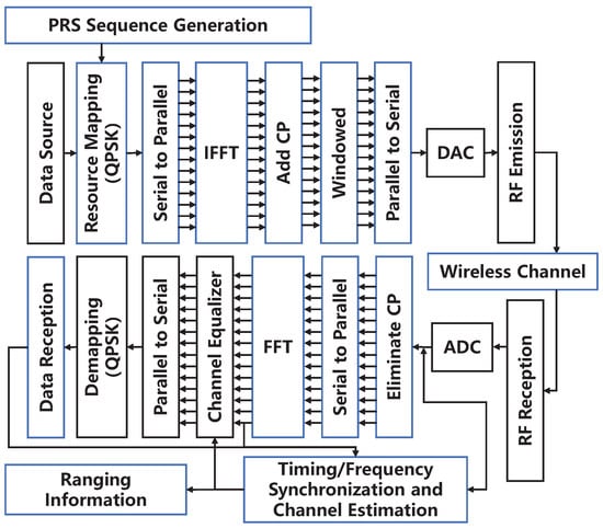
Figure 1.
5G NR Co-Band communication and positioning fusion system.
2.2. 5G NR Co-Band PRS Signal Model
According to 3GPP TS 38.211 V17.0.0, the reference signal sequence is defined by
The PRS initialization sequence is defined as
where is the slot time, determined by the higher-layer parameter DL-PRS-Subcarrier. The downlink PRS sequence ID is given by the higher-layer parameter dl-PRS-SequenceID and l is the OFDM symbol within the slot to which the sequence is mapped. For each downlink PRS resource configured, the UE shall assume the sequence is scaled with a factor and mapped to resource elements . We define the mapping function as , and then we obtain
where k denotes the frequency domain mapping number of the resource grid and l denotes the time domain mapping number of the resource grid. In order to prevent interference of the positioning signal to the communication signal, should be significantly less than 1.
The communication data are spread over the whole resource block, which is configured according to the UE’s needs and can be expressed as
The PRS sequence and the communication data sequence are mapped and superimposed to generate , where N represents the number of fast Fourier transform points and i represents the number of OFDM symbols in the time domain. It should be noted that the number of subcarriers used is , and N is a power of 2. The superimposed signal can be expressed as
At the transmitter side, an N-point IFFT is constructed by adding zeros after the useful data. Addditionally, a cyclic prefix of length needs to be added before the OFDM symbols to prevent intersymbol interference (ISI). To ensure the orthogonality between subcarriers, the length of needs to be greater than or equal to the maximum delay of the multipath channel. At this point, the transmitted baseband signal in the time domain can be expressed as
where , denotes the useful symbol interval.
2.3. Co-Band PRS Receive Signal Model
In wireless communication systems, ensuring the synchronization of received signals requires considering the effects of STO, CFO, and sampling clock offset. Sample clock offset include phase offset and frequency offset. Sample clock phase offset is absorbed by the STO, while sample clock frequency offset has a minimal effect and can usually be neglected. The focus of this paper is not on the CFO; common carrier frequency synchronization algorithms can be found in [23,24,25] which are compatible with the algorithms discussed in this paper. Therefore, in an indoor multipath fading channel, we model the arrival time of the multipath time delay component as a Poisson process and establish the channel impulse response as
where denotes the arrival time of the r-th ray in the p-th cluster, and the arrival time of the first ray of the p-th cluster is defined as . For ranging, our goal is to identify the first arrival path of the first cluster. The channel frequency response can be described as
At the receiver side, assuming that it has been downconverted back to baseband, the baseband signal is sampled at intervals to obtain the discrete baseband received signal as
where and denote the normalized CFO and STO, respectively.
3. Proposed Timing Recovery Scheme
In general, to obtain more accurate time delay estimates, symbol synchronization is divided into two steps: coarse and fine synchronization. For coarse synchronization, we utilize a CP-based estimation method that estimates the STO while estimating the residual fractional CFO. It should be noted that the code type information of PRS is determined through the 5G new radio (NR) higher-layer configuration information. And blindly capturing the PRS signal undoubtedly increases the complexity of the system. In addition, information regarding base station location and subcarrier interval cannot be obtained from the positioning signal itself. Therefore, it is necessary to perform the coarse synchronization process using the synchronization signal and physical broadcast channel (PBCH) block (SSB). This process helps obtain auxiliary information used for localization, such as cell ID, base station location, and subcarrier spacing. For fine synchronization, path delay estimation is necessary, and the signal is converted to the frequency domain to track the code phase. Considering that the Co-Band PRS is superimposed on the communication signal, pre-processing is required to eliminate the influence of the communication signal on the positioning signal prior to fine synchronization. In this paper, the overall architecture of timing recovery scheme for the Co-Band PRS is shown in Figure 2.
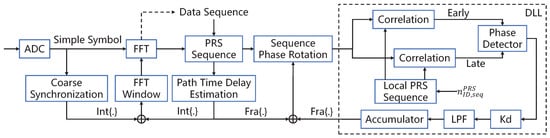
Figure 2.
The proposed 5G NR Co-band PRS reception framework.
3.1. Coarse Synchronization Solution
For coarse synchronization of the signal, a CP-based timed symbol synchronization method can be used, which exploits the repetitive characteristics of the CP [26]. Also, to mitigate the influence of the CFO, the coarse synchronization scheme is implemented by
where and denote the estimated value of the signal STO and CFO, respectively. In addition, [27]. It is worth noting that at this point, the minimum granularity of is one sampling unit, while can be used to compensate for the residual CFO.
However, in the actual sampling process, it is inevitable to truncate the time domain signal with a long sampling time into blocks of data of frame-by-frame length. To avoid spectral leakage caused by non-integer period truncated signals, it is common practice to apply a windowing function to the signal. 5G NR uses a rising cosine roll-off windowing function for each OFDM symbol in subframes, as shown in Figure 3 below.
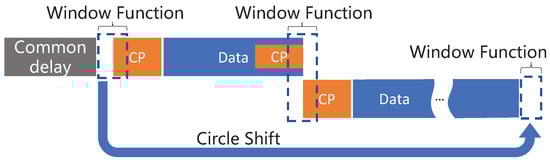
Figure 3.
Schematic of the rising cosine roll-off window in 5G NR.
Due to the presence of the window function, the window paraflap of the latter symbol overlaps with the tail of the previous symbol, resulting in a significant bias in the CP-based STO estimation method. Therefore, the existing method needs to incorporate weighted corrections, and the weighted function is set as
where n denotes the signal truncation length and e denotes the window length. The coarse synchronization scheme was amended by
Next, we need to obtain location-assisted information such as the physical layer cell ID , subcarrier spacing, and the starting position of the PRS in the resource grid (referred to as PointA) via the SSB. Since this part usually occurs during the initial network search process in the UE, there is no additional overhead for the UE. The specific process is as follows. The UE first searches for the primary synchronization signal (PSS) and secondary synchronization signal (SSS) to determine the center frequency and physical cell ID (PCI) of the SSB. Then, the subcarrier frequency offset of the SSB (i.e., kSSB) and the physical downlink control channel (PDCCH) carrying the scheduling information, which determines the time-frequency location of control-resource set (CORESET), are obtained via PBCH. Finally, the PointA and system bandwidth are obtained by monitoring system information block 1 (SIB1).
In addition, the current PSS/SSS signals of 5G NR are generated by m-Sequence of length bit 127, where PSS is determined by and SSS is determined jointly by and . The corresponding cell ID is determined by
3.2. Multi-Path Delay Estimation
For indoor multipath environments, path delay estimation is particularly important. We further analyze multipath delay by estimating the time-domain channel. In general, accurate channel estimation requires high-power pilot signals [28], while Co-Band PRS signals are inherently low-power. Although this paper reduces noise interference by implementing window filtering [29], it is not possible to eliminate the communication data that are superimposed on the Co-Band PRS signal using this method. However, the communication data superimposed on the PRS localization signal become the main source of interference and cannot be eliminated in this way. In this regard, there are two approaches to consider. Firstly, increasing the number of subcarriers and using a short comb structure like Comb2 can enhance the localization signal correlation characteristics by extending the localization signal length. Secondly, this paper proposes improving the time delay estimation performance by pre-demodulating the data information and eliminating the data codes.
Firstly, the Co-Band PRS signal in the i-th OFDM symbol is defined as , where the value of Q is determined by the number of subcarriers occupied by the PRS of the i-th OFDM symbol in the frequency domain. And polit signal may also contain communication data that can be given by
where is the estimated data code, obtained directly by Fourier transforming the signal after the initial coarse capture and decoding it. We perform an FFT on the received signal, and by utilizing time-frequency mapping, we can obtain
where is the time delay estimate obtained through coarse capture, and denotes the path fading factor. Dividing this by the original pilot signal yields an estimate of the channel’s frequency domain response as
The estimated channel is passed through a Hamming window to minimize the effect of IFFT symbol leakage. It is then transformed to the time domain using a Q-point IFFT. The estimated channel impulse response can be obtained as
Due to the influence of multipath, the channel time-domain impulse response contains multiple path components. Often, the strongest path is not the first path reached. To address this, we introduce a threshold, denoted as . We consider the first path whose power exceeds this threshold as the first reach path and update the timing estimation by
For the integer part of , it will be sent back to the FFT window block in Figure 2 to correct the window function position. The fractional part of will be sent to the sequence phase rotation block in Figure 2 to correct the Co-Band PRS phase. If the integer part of exists, the data also need to be re-estimated according to the new FFT window position.
3.3. Delay-Locked Loop Design
The corrected Co-Band PRS signal is fed to the DLL and we perform phase compensation for the PRS symbol as follows:
where and denote the integer and fractional parts of the timing estimation, and denotes the output of the DLL. The composition of the DLL mainly includes correlator, discriminator, and loop filter. The local generated early and late reference pilots of the Co-Band PRS are generated by
where is the normalized OFDM time shift; in this paper, is set to 1/2. The early and late correlations in the frequency domain can be expressed, respectively, as
In order to improve performance, we process the above results with incoherent integrals to obtain
After obtaining the noncoherent integrals of the early and late branches, the correlation values need to be discriminated in order to obtain accurate phase values. Common code loop discriminators include the noncoherent early-late amplitude method, the noncoherent early-late power method, and the seemingly coherent dot product power method [30,31]. In this paper, the noncoherent early-late power method is used, and the normalized S-curve function is described as
where represents the square of the signal amplitude, and is the gain coefficient that guarantees normalization. The DLL S-curve is shown in Figure 4. And the proposed iterative DLL algorithm is shown in Algorithm 1.
| Algorithm 1 Iterative DLL algorithm |
Input: , , Output:
|
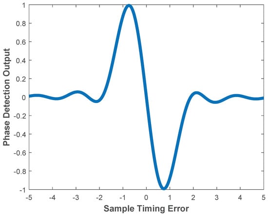
Figure 4.
Normalized S-curve function for the case of .
4. Simulation Results and Errors Analysis
Considering the simulation in an indoor multipath Rician fading channel, in order to improve the tracking capability, we suggest configuring the Co-Band PRS as a continuous signal. This is achieved by increasing the symbol length of PRS in one time slot and configuring and to be equal. This configuration increase the duty cycle of the Co-Band PRS signal in the time domain. The specific configuration is shown in Table 1.

Table 1.
Specific configuration of Co-Band PRS parameters.
4.1. Simulation and Analysis
For coarse synchronization, we can only estimate the integer time error of sampling units. For a particular snapshot, we set a delay of 3887 samples with a sampling rate of 122.88 MHz. We evaluated the performance of coarse synchronization at SNR values of 10 dB, 30 dB, and 50 dB, respectively (see Figure 5). It can be observed that as the SNR increases from 10 dB to 50 dB, the accuracy of the estimation using the traditional ML-based method [26] increases from 13% to 62%. Therefore, the traditional method can only determine the STO by selecting the maximum probability from multiple estimations. The method proposed in this paper still achieves 99% accuracy even at an SNR of 10 dB.
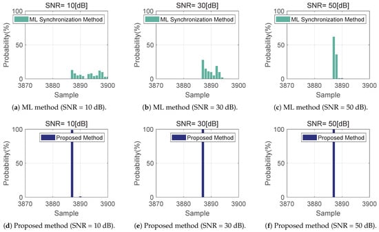
Figure 5.
Coarse synchronization estimation under Gaussian noise.
For indoor areas, the time delay extension is generally at the hundred nanosecond level. For this reason, the multipath delay of Rice channel is set to {0, 6, 10, 40} samples, and the average gain is {0 dB, −2 dB, −5 dB, −10 dB}. The K factor of Rician fading is set to 4, which represents the power ratio between direct and scattered components, while keeping other settings constant. At this time, as the SNR increases from 10 dB to 50 dB, the estimation accuracy of the traditional ML-based method increases from 9% to 34%. While the accuracy of the proposed method decreases to 52% and 92% for 10 dB and 30 dB SNR conditions, it maintains full accuracy in the 50 dB SNR case (see Figure 6). It can be seen that the Rician channel has a greater impact on coarse synchronization. Therefore, to ensure accurate estimation of the FFT window positions, it is recommended to estimate multiple OFDM symbols simultaneously and select the position with the highest probability.
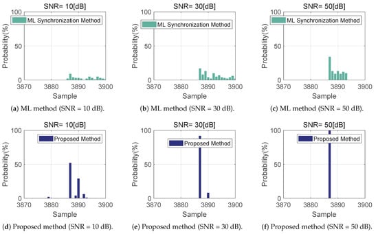
Figure 6.
Coarse synchronization estimation under Rician channel.
For the multipath delay estimation, the simulation is still performed in the aforementioned Rician channel with a fixed noise level of 30 dB. The is estimated by averaging 10 symbols to ensure the accuracy. On this basis, the performance of multipath delay estimation without removing the communication signal is analyzed, as shown in Figure 7a. Because the power of the communication signal is 40 dB higher than that of the localization signal, and the Co-Band PRS signal uses only a 20 RB bandwidth, its correlation characteristics are not excellent. Since there is no way to detect the first arrivals, the ranging information is invalid for the localization user at this point. Of course, we further explored the power limit of the positioning signal, and we found that the first-arrival path is weakly detected when the positioning signal is 16 dB lower than the communication signal (Figure 7b), but the estimated channel implicit response is still inaccurate.
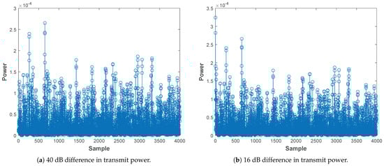
Figure 7.
Estimation of the channel impluse response by treating the communication signal as noise. (a) The positioning signal transmitting power is 40 dB lower than the communication signal transmitting power (). (b) The positioning signal transmitting power is 16 dB lower than the communication signal transmitting power ().
Next, we explored the effect of Co-Band PRS signals on communication signals. Since the Co-Band PRS power is extremely low, it has almost no impact on the bit error rate (BER) of the communication signal, as shown in Figure 8a. For this reason, we first consider signal detection of the communication signal. Then, we calculate the pilot signal that only contains the Co-Band PRS using Equation (17). At this stage, we can accurately estimate the main path and three multipaths of the Rician channel (Figure 8b). This further confirms that interference cancellation techniques can eliminate the interference of communication signals on the positioning signals. As a result, it enables a more accurate differentiation of the first arriving path of the positioning signals.
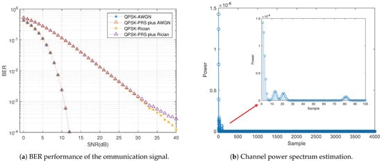
Figure 8.
Performance analysis. (a) BER performance of the ommunication signal (). (b) Channel power spectrum estimation after elimination of communication data.
To evaluate the performance of the iterative DLL, we inject some fractional timing into the OFDM symbols before modulation at the transmitter. The transmitted signal can given by
where the fractional timing error is defined as
For the AWGN-only channel, the experimental results show that the RMSE is samples and the standard deviation of the code phase samples is samples (Figure 9). For the Rice plus Gaussian noise channel, the results show that the code phase RMSE is samples, and the code phase sample standard deviation is samples (Figure 10). It is easy to observe that the tracking accuracy increases as the tracking time increases. The simulation results demonstrate that the Co-Band PRS signal reception scheme detailed in this paper can successfully track timing errors regardless of different channel environments, thus providing a good candidate for high-precision localization in mobile communication networks. From Figure 11, we observe that the tracking accuracy improves as the number of iterations increases. However, the rate of improvement begins to decrease when the number of iterations reaches 5.
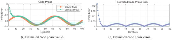
Figure 9.
DLL tracking results under AWGN channel.
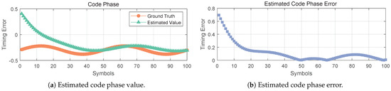
Figure 10.
DLL tracking results under Rician plus AWGN channel.
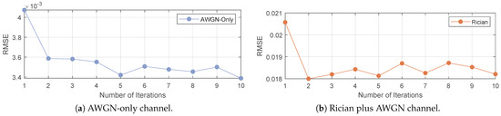
Figure 11.
RMSE of DLL tracing results at different number of iterations.
4.2. Experimental Results
To verify the ranging performance, we use two USRPs as the transmitter and receiver, respectively, to conduct the actual test of the aforementioned scheme. The Co-Band PRS signal is generated in real time by the positioning server and then connected to a switch to ensure that the devices are on the same network segment. For the signal source, the USRP uses two antenna ports, each connected with an equal length of coaxial cable to extend the indoor antenna’s reach. A rubidium atomic clock is installed as the clock source to ensure that two orthogonal Co-Band PRS signals are broadcasted simultaneously. The USRP at the receiving end uses one antenna port to receive the two signals, utilizing the local clock reference. The experimental environment and equipment connections are shown in Figure 12.
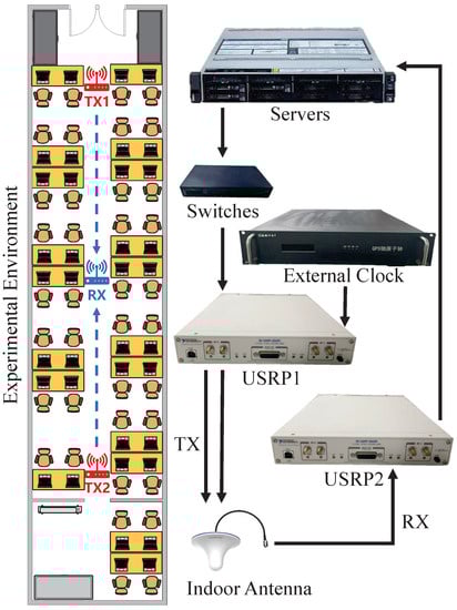
Figure 12.
Test environment and equipment connection diagram.
To remove the ambiguity of whole cycles, we track two Co-Band PRS signals that are transmitted simultaneously and determine the receiver’s one-dimensional position by calculating the code phase difference. We first correlate the received signal directly with the locally generated signal in the time domain (as shown in Figure 13a). At this time, the two signals differ by a distance of two code slices, which is equivalent to a distance difference of 4.88 m (since each code slice is approximately 2.44 m). However, the actual difference in distance measured using the laser rangefinder is 3.24 meters, indicating the presence of significant errors in the direct correlation method in the time domain. By changing the position of the receiver antenna and taking several measurements, we collected 100 sets of Co-Band signal data. The ranging performance of Co-Band signals was analyzed using the time-domain direct correlation method [7], the MUSIC ranging method [16], and the iterative DLL tracking method proposed in this paper, respectively. As can be seen from Figure 13b, the ranging accuracy of the proposed method can reach 0.16 m@90%, and its performance is better than that of the MUSIC algorithm with ten times sampling frequency.
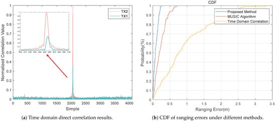
Figure 13.
Test results in real environment.
5. Conclusions
In this paper, we propose a high-precision ranging scheme based on 5G NR Co-Band signals. This scheme does not take up additional 5G communication resources and can realize fast capture and high-precision tracking of signals in multipath environments. Firstly, the receiving and transmitting models of the Co-Band PRS signal are introduced, and the general framework of the timing recovery scheme for this signal is provided. Then, we have designed a weighted window capture method to enhance the coarse synchronization performance of Co-Band signals in low-SNR conditions. We improve the accuracy of path time delay estimation and multipath tracking by pre-estimating the communication signals using the low-power characteristics of Co-Band signals. In addition, we propose the iterative DLL method, and simulation results show that the code phase RMSE is samples. Finally, the USRP is utilized to construct an indoor multipath environment, and the final ranging accuracy reaches 0.16 m@90%.
However, due to the experimental conditions, only the ranging performance in an indoor environment is measured in this paper. The focus of future research will be on the design of higher-order phase-locked loop-aided DLL for highly dynamic environments and how to overcome the near–far effect under multi-base station conditions.
Author Contributions
K.L. and Z.D. are both the principal investigators; X.G., Z.M. and J.L. assisted K.L. in conceiving and conducting the experiments and analysis; K.L. analyzed the data and wrote the paper. All authors have read and agreed to the published version of the manuscript.
Funding
This work was financially supported by the National Key Research and Development Program of China (No. 2022YFB3904603).
Data Availability Statement
The data that support the findings of this study are available from the corresponding author upon reasonable request.
Conflicts of Interest
The authors declare no conflict of interest.
References
- Bencak, P.; Hercog, D.; Lerher, T. Indoor positioning system based on bluetooth low energy technology and a nature-inspired optimization algorithm. Electronics 2022, 11, 308. [Google Scholar] [CrossRef]
- Shang, S.; Wang, L. Overview of wifi fingerprinting-based indoor positioning. IET Commun. 2022, 16, 725–733. [Google Scholar] [CrossRef]
- Wang, F.; Tang, H.; Chen, J. Survey on nlos identification and error mitigation for uwb indoor positioning. Electronics 2023, 12, 1678. [Google Scholar] [CrossRef]
- Zhu, N.; Marais, J.; Bétaille, D.; Berbineau, M. Gnss position integrity in urban environments: A review of literature. IEEE Trans. Intell. Transp. Syst. 2018, 19, 2762–2778. [Google Scholar] [CrossRef]
- Wang, C.-X.; Haider, F.; Gao, X.; You, X.-H.; Yang, Y.; Yuan, D.; Aggoune, H.M.; Haas, H.; Fletcher, S.; Hepsaydir, E. Cellular architecture and key technologies for 5g wireless communication networks. IEEE Commun. Mag. 2014, 52, 122–130. [Google Scholar] [CrossRef]
- del Peral-Rosado, J.A.; Raulefs, R.; López-Salcedo, J.A.; Seco-Granados, G. Survey of cellular mobile radio localization methods: From 1 g to 5 g. IEEE Commun. Surv. Tutor. 2017, 20, 1124–1148. [Google Scholar] [CrossRef]
- Müürsepp, I.; Kulmar, M.; Elghary, O.; Alam, M.M.; Chen, T.; Horsmanheimo, S.; Scholliers, J. Performance evaluation of 5g-nr positioning accuracy using time difference of arrival method. In Proceedings of the 2021 IEEE International Mediterranean Conference on Communications and Networking (MeditCom), Athens, Greece, 7–10 September 2021; pp. 494–499. [Google Scholar]
- Mendrzik, R.; Wymeersch, H.; Bauch, G.; Abu-Shaban, Z. Harnessing nlos components for position and orientation estimation in 5 g millimeter wave mimo. IEEE Trans. Wirel. Commun. 2018, 18, 93–107. [Google Scholar] [CrossRef]
- Huo, Y.; Lin, X.; Di, B.; Zhang, H.; Hernando, F.J.L.; Tan, A.S.; Mumtaz, S.; Demir, T.; Chen-Hu, K. Technology trends for massive mimo towards 6 G. Sensors 2023, 23, 6062. [Google Scholar] [CrossRef]
- Mazloum, T.; Santamaria, L.; Munoz, F.; Clemente, A.; Gros, J.-B.; Nasser, Y.; Odit, M.; Lerosey, G.; D’Errico, R. Impact of multiple ris on channel characteristics: An experimental validation in ka band. In Proceedings of the 2023 Joint European Conference on Networks and Communications & 6G Summit (EuCNC/6G Summit), Gothenburg, Sweden, 6–9 June 2023; IEEE: New York, NY, USA, 2023; pp. 13–18. [Google Scholar]
- Luan, M.; Wang, B.; Zhao, Y.; Feng, Z.; Hu, F. Phase design and near-field target localization for ris-assisted regional localization system. IEEE Trans. Veh. Technol. 2021, 71, 1766–1777. [Google Scholar] [CrossRef]
- Leitinger, E.; Meissner, P.; Rüdisser, C.; Dumphart, G.; Witrisal, K. Evaluation of position-related information in multipath components for indoor positioning. IEEE J. Sel. Areas Commun. 2015, 33, 2313–2328. [Google Scholar] [CrossRef]
- Li, X.; Pahlavan, K. Super-resolution toa estimation with diversity for indoor geolocation. IEEE Trans. Wirel. Commun. 2004, 3, 224–2344. [Google Scholar] [CrossRef]
- Roy, R.; Kailath, T. Esprit-estimation of signal parameters via rotational invariance techniques. IEEE Trans. Acoust. Speech Signal Process. 1989, 37, 984–995. [Google Scholar] [CrossRef]
- Driusso, M.; Babich, F.; Knutti, F.; Sabathy, M.; Marshall, C. Estimation and tracking of lte signals time of arrival in a mobile multipath environment. In Proceedings of the 2015 9th International Symposium on Image and Signal Processing and Analysis (ISPA), Zagreb, Croatia, 7–9 September 2015; pp. 276–281. [Google Scholar]
- Wang, Y.; Li, C.; Yu, Y.; Huang, S. Enabling low-power high-accuracy positioning (lphap) in 3gpp nr standards. In Proceedings of the 2021 International Conference on Indoor Positioning and Indoor Navigation (IPIN), Lloret de Mar, Spain, 29 November–2 December 2021; pp. 1–7. [Google Scholar]
- Yang, B.; Letaief, K.B.; Cheng, R.S.; Cao, Z. Timing recovery for ofdm transmission. IEEE J. Sel. Areas Commun. 2000, 18, 2278–2291. [Google Scholar] [CrossRef]
- Thevenon, P.; Julien, O.; Macabiau, C.; Serant, D.; Corazza, S.; Bousquet, M.; Ries, L.; Grelier, T. Pseudo-range measurements using ofdm channel estimation. In Proceedings of the 22nd International Technical Meeting of the Satellite Division of the Institute of Navigation (ION GNSS 2009), Savannah, GA, USA, 22–25 September 2009; pp. 481–493. [Google Scholar]
- Shamaei, K.; Kassas, Z.M. Lte receiver design and multipath analysis for navigation in urban environments. Navigation 2018, 65, 655–675. [Google Scholar] [CrossRef]
- Jin, C.; Bajaj, I.; Zhao, K.; Tay, W.P.; Ling, K.V. 5g positioning using code-phase timing recovery. In Proceedings of the 2021 IEEE Wireless Communications and Networking Conference (WCNC), Nanjing, China, 29 March–1 April 2021; pp. 1–7. [Google Scholar]
- Yin, L.; Cao, J.; Lin, K.; Deng, Z.; Ni, Q. A novel positioning-communication integrated signal in wireless communication systems. IEEE Wirel. Commun. Lett. 2019, 8, 1353–1356. [Google Scholar] [CrossRef]
- Sharifi-Tehrani, O.; Sabahi, M.F.; Danaee, M.R. Efficient gnss jamming mitigation using the marcenkopastur law and karhunen-loeve decomposition. IEEE Trans. Aerosp. Electron. Syst. 2021, 58, 2291–2303. [Google Scholar] [CrossRef]
- Lee, J.-H.; Han, J.C.; Kim, S.-C. Joint carrier frequency synchronization and channel estimation for ofdm systems via the em algorithm. IEEE Trans. Veh. Technol. 2006, 55, 167–172. [Google Scholar] [CrossRef]
- Morelli, M.; Moretti, M. Fine carrier and sampling frequency synchronization in ofdm systems. IEEE Trans. Wirel. Commun. 2010, 9, 1514–1524. [Google Scholar] [CrossRef]
- Gul, M.M.U.; Ma, X.; Lee, S. Timing and frequency synchronization for ofdm downlink transmissions using zadoff-chu sequences. IEEE Trans. Wirel. Commun. 2014, 14, 1716–1729. [Google Scholar] [CrossRef]
- de Beek, J.-J.V.; Sandell, M.; Borjesson, P.O. Ml estimation of time and frequency offset in ofdm systems. IEEE Trans. Signal Process. 1997, 45, 1800–1805. [Google Scholar] [CrossRef]
- Beek, J.-J.V.D.; Sandell, M.; Isaksson, M.; Borjesson, P.O. Low-complex frame synchronization in ofdm systems. In Proceedings of the ICUPC’95-4th IEEE International Conference on Universal Personal Communications, Tokyo, Japan, 6–10 November 1995; pp. 982–986. [Google Scholar]
- Ren, X.; Chen, W.; Tao, M. Position-based compressed channel estimation and pilot design for high-mobility ofdm systems. IEEE Trans. Veh. Technol. 2014, 64, 1918–1929. [Google Scholar] [CrossRef]
- Tao, L.; Yu, J.; Zhang, J.; Shao, Y.; Chi, N. Reduction of intercarrier interference based on window shaping in ofdm rof systems. IEEE Photonics Technol. Lett. 2013, 25, 851–854. [Google Scholar] [CrossRef]
- Rinder, P.; Bertelsen, N. Design of a Single Frequency GPS Software Receiver; Aalborg Universitet, Institute of Electronic Systems: Nordjylland, Denmark, 2004. [Google Scholar]
- Kaplan, E.D.; Hegarty, C. Understanding GPS/GNSS: Principles and Applications; Artech House: Norwood, MA, USA, 2017. [Google Scholar]
Disclaimer/Publisher’s Note: The statements, opinions and data contained in all publications are solely those of the individual author(s) and contributor(s) and not of MDPI and/or the editor(s). MDPI and/or the editor(s) disclaim responsibility for any injury to people or property resulting from any ideas, methods, instructions or products referred to in the content. |
© 2023 by the authors. Licensee MDPI, Basel, Switzerland. This article is an open access article distributed under the terms and conditions of the Creative Commons Attribution (CC BY) license (https://creativecommons.org/licenses/by/4.0/).