
Active Support System for the Correction of a 4m SiC Primary Mirror Based on the Bending Mode

Abstract
:1. Introduction
2. Principle and Structural Design of the Active Support System for a 4m SiC Primary Mirror
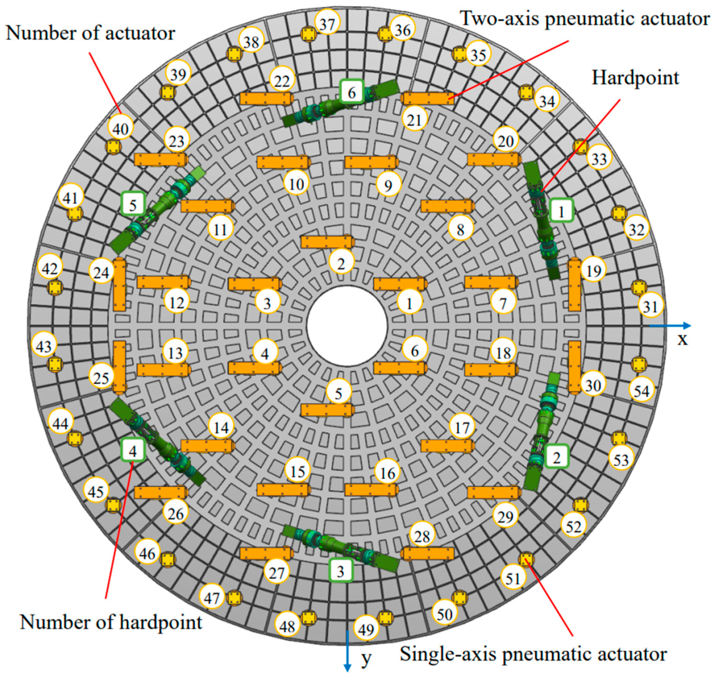
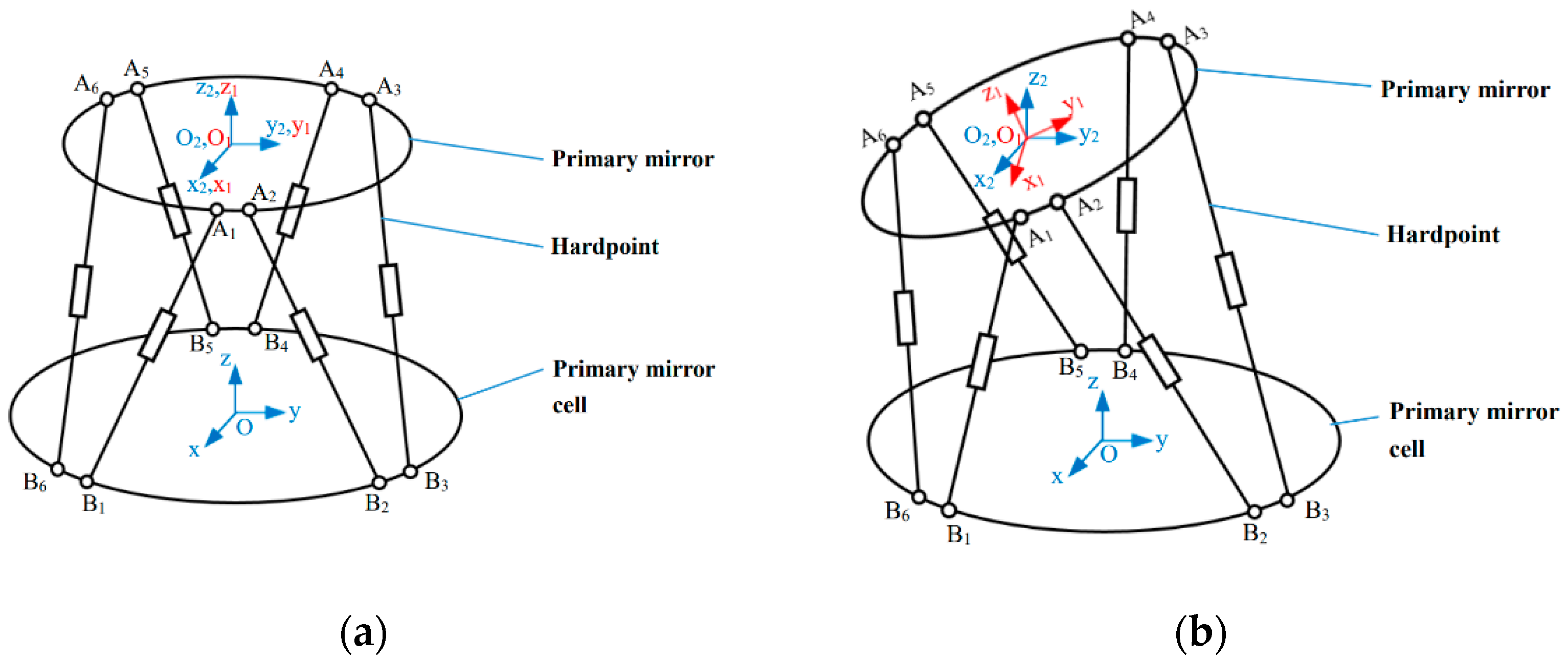
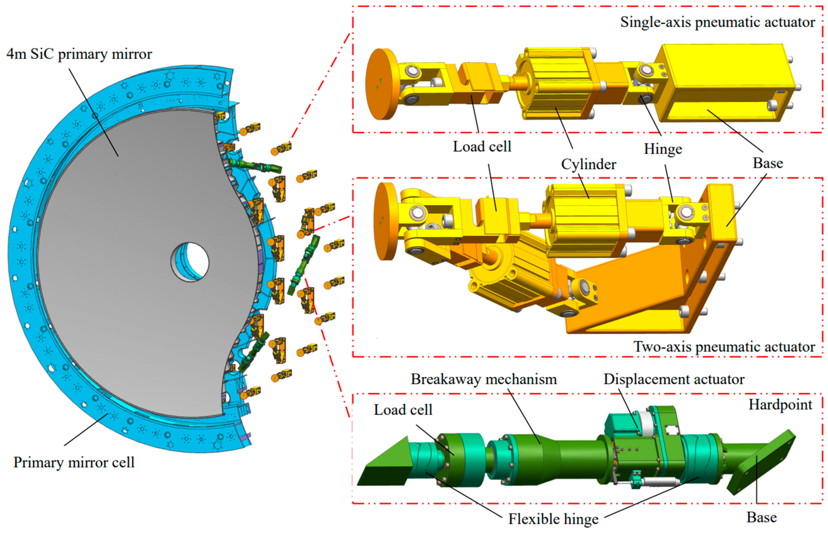
2.1. Pneumatic Surface Control Actuators and Hardpoints
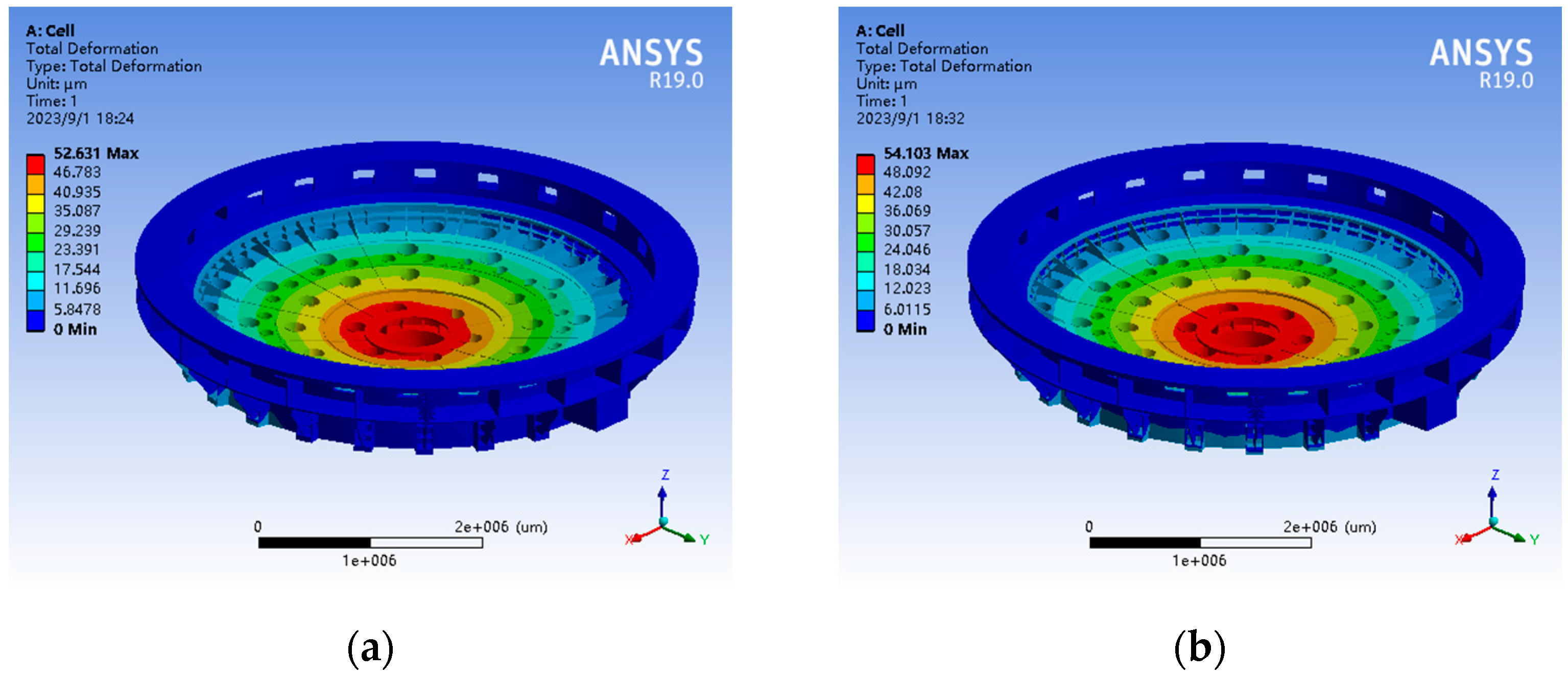
2.2. Finite Element Model of the Active Support System for the 4m SiC Primary Mirror
3. Active Optics Correction of the 4m SiC Primary Mirror
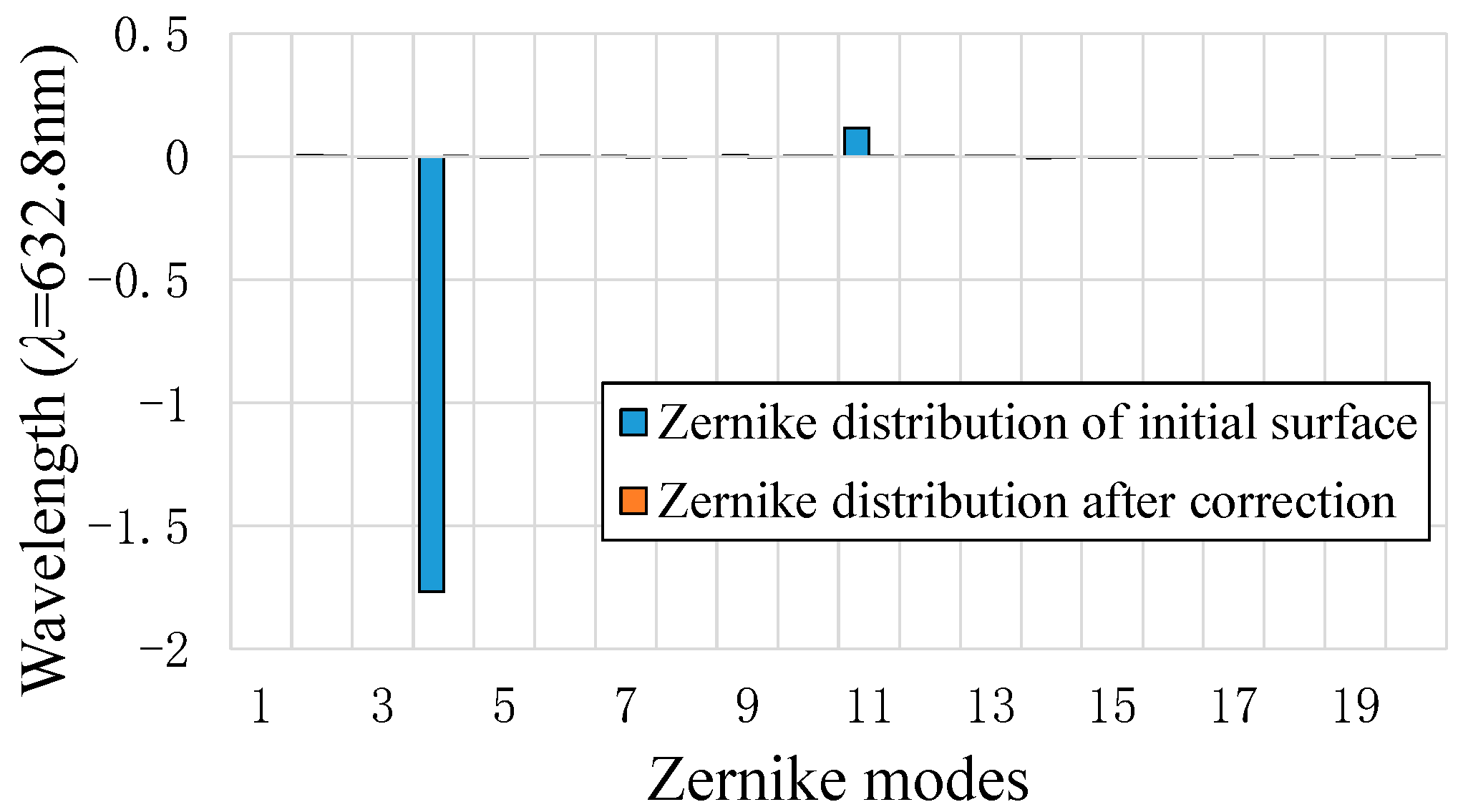
3.1. Surface Shape Correction of the 4m SiC Primary Mirror
3.1.1. Principle of Surface Shape Correction Based on the Bending Mode
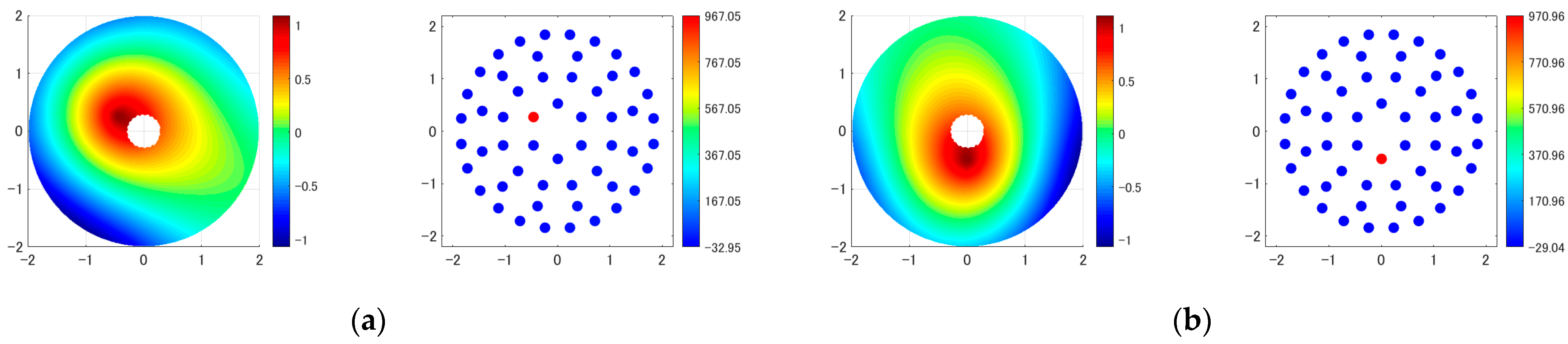
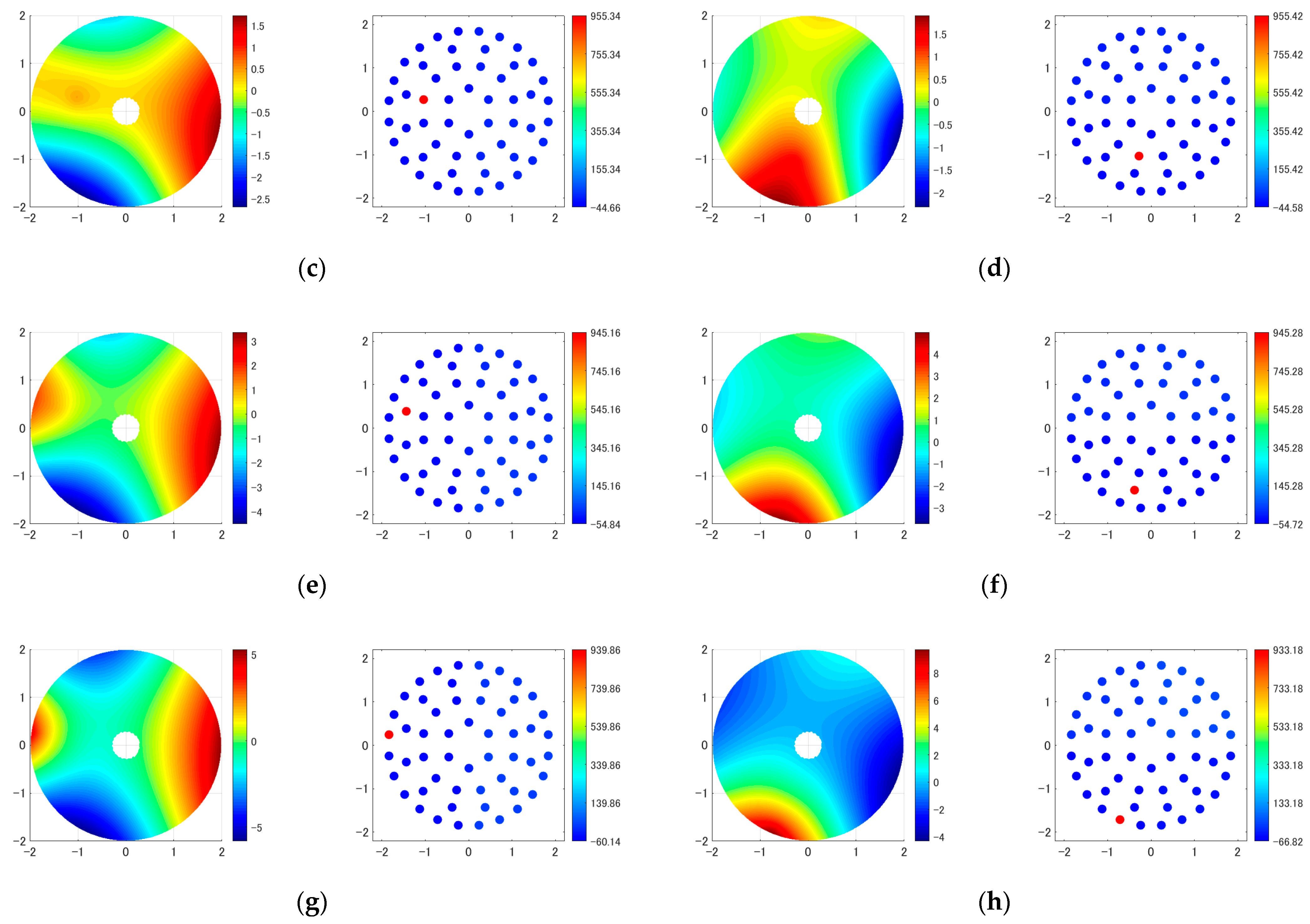
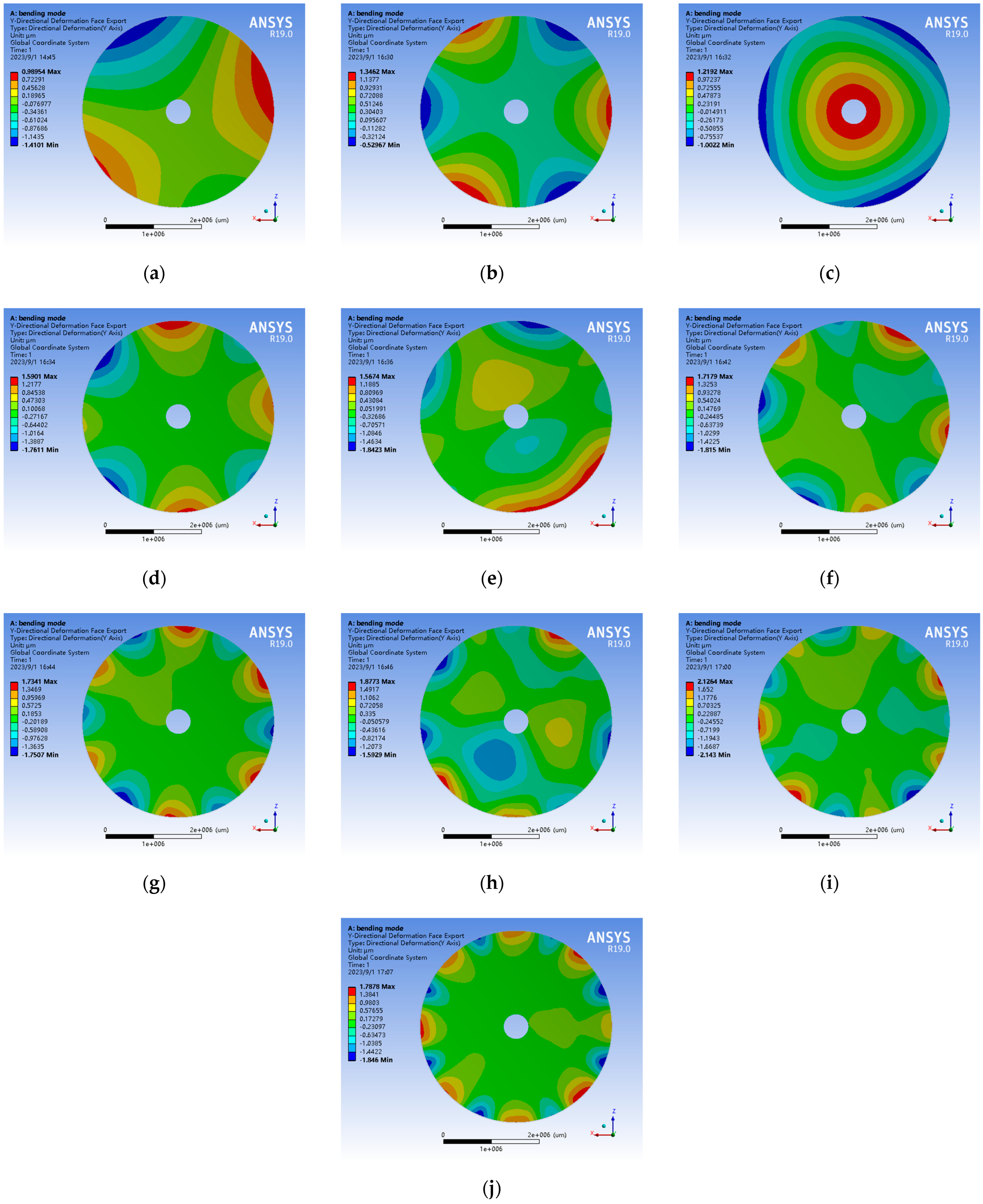
3.1.2. Influence Function and Bending Mode of the 4m SiC Primary Mirror
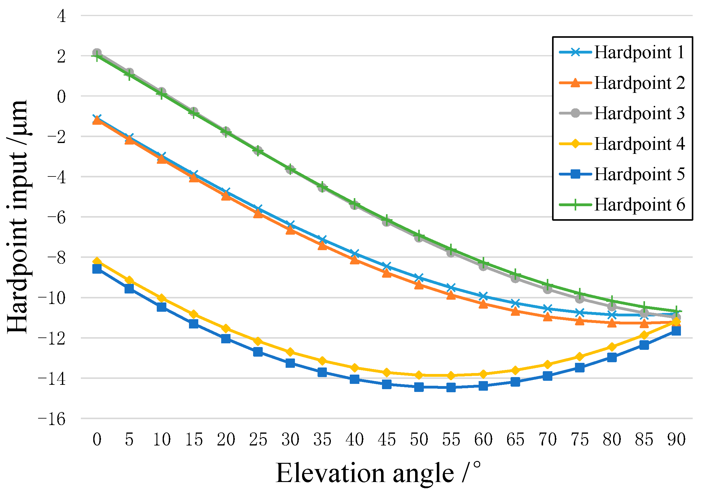
3.2. Pose Correction of the 4m SiC Primary Mirror
3.3. Influence of Force on Hardpoints on the Surface Shape of the 4m SiC Primary Mirror and Compensation Methods
4. Performance Evaluation of the Active Support System for the 4m SiC Primary Mirror
4.1. Verification of the Bending Mode
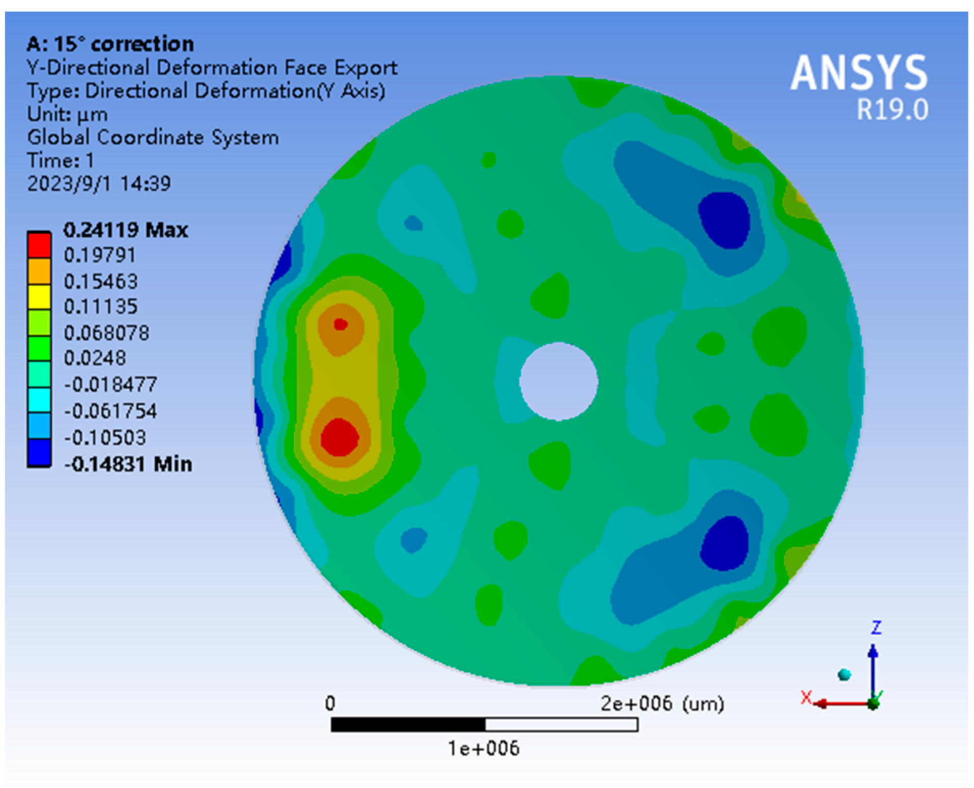
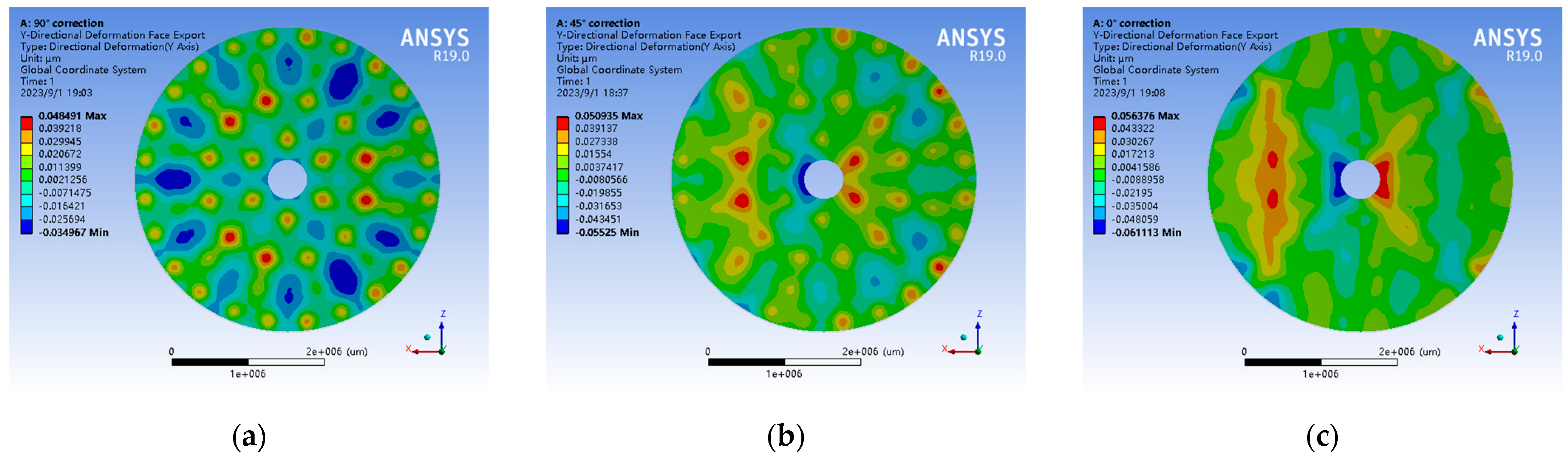
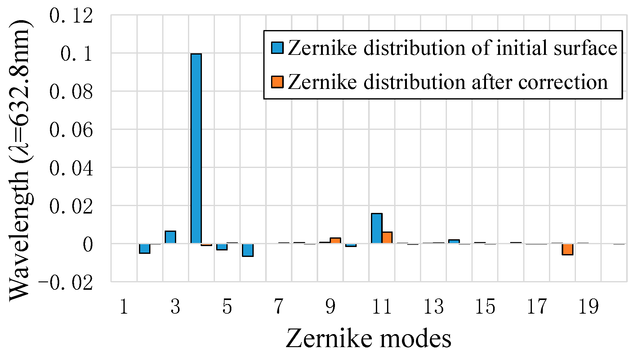
4.2. Correction of Gravity Deformation of the Primary Mirror
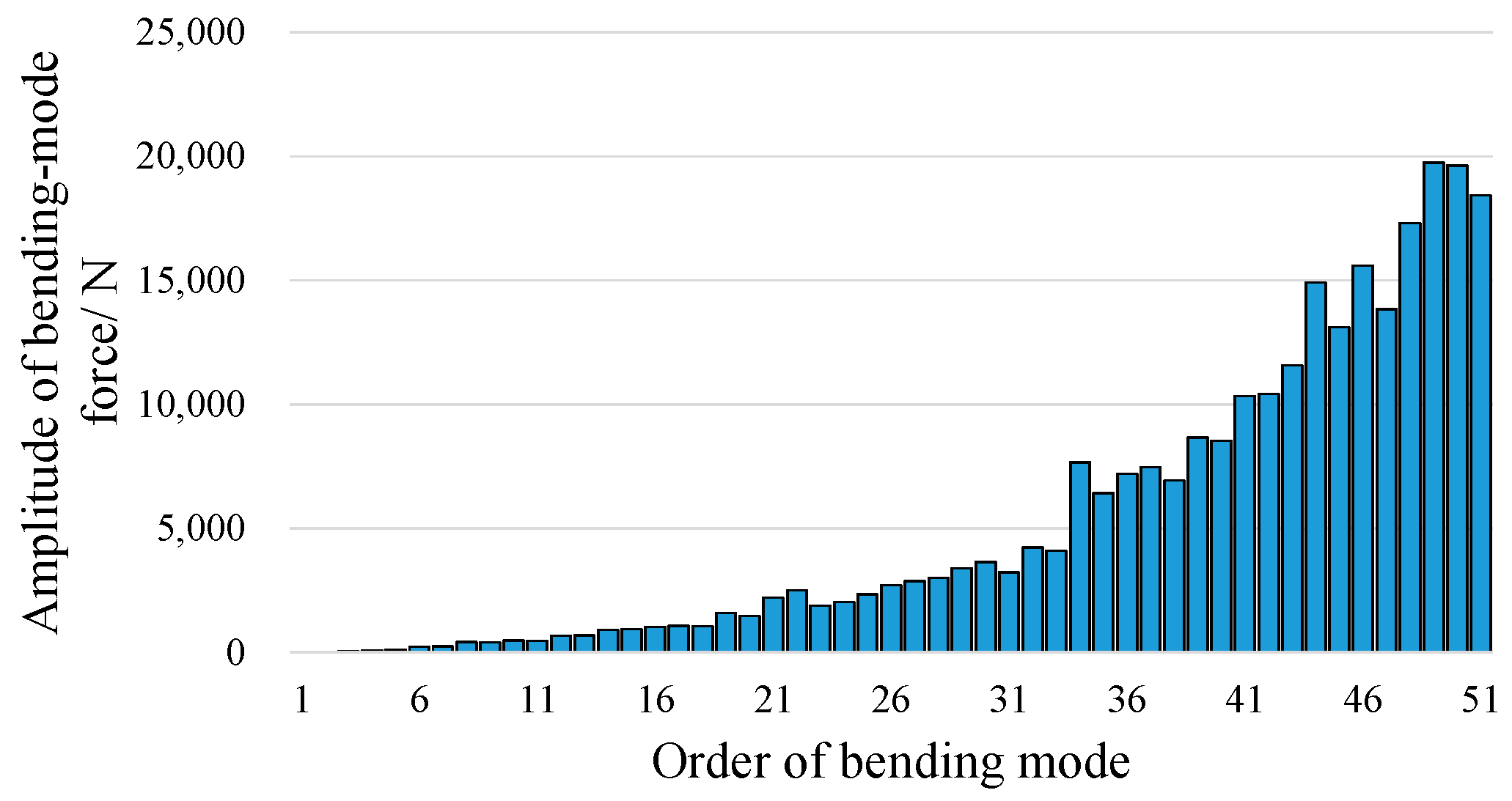
4.3. Relationship between the Orders of Bending Modes and the Correction Effect
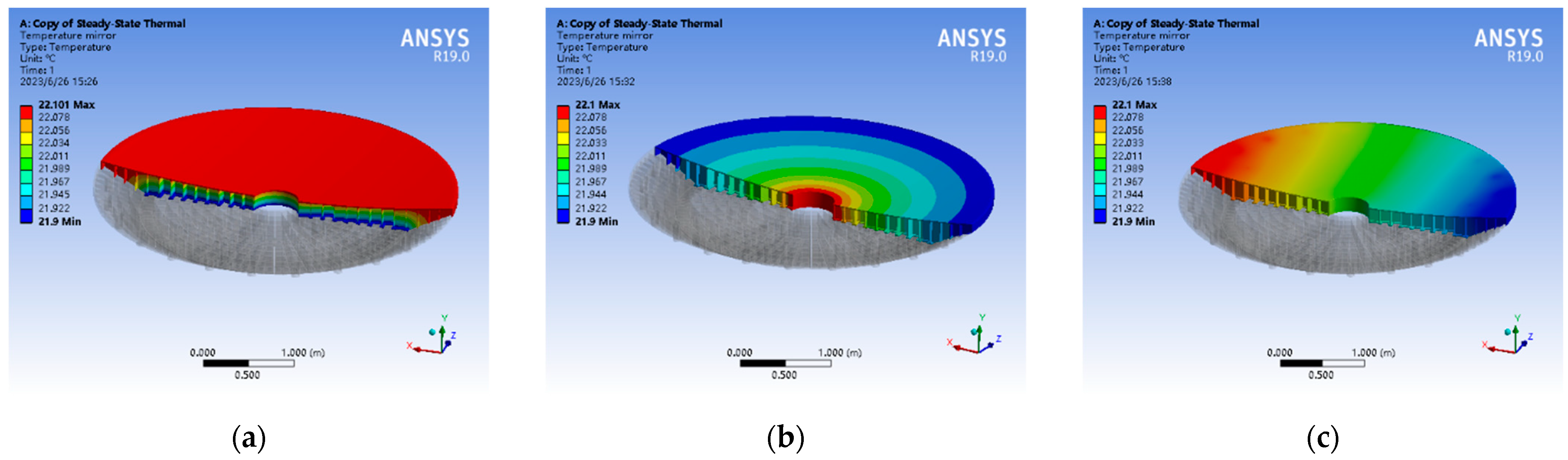
4.4. Correction of the Primary Mirror Surface Shape Errors Caused by Thermal and Wind Loads
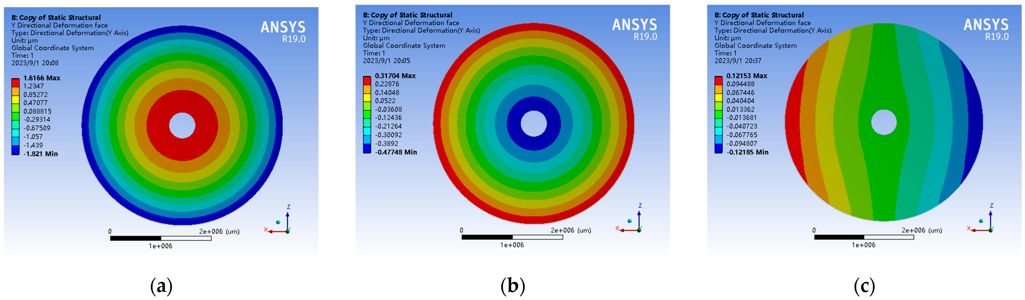
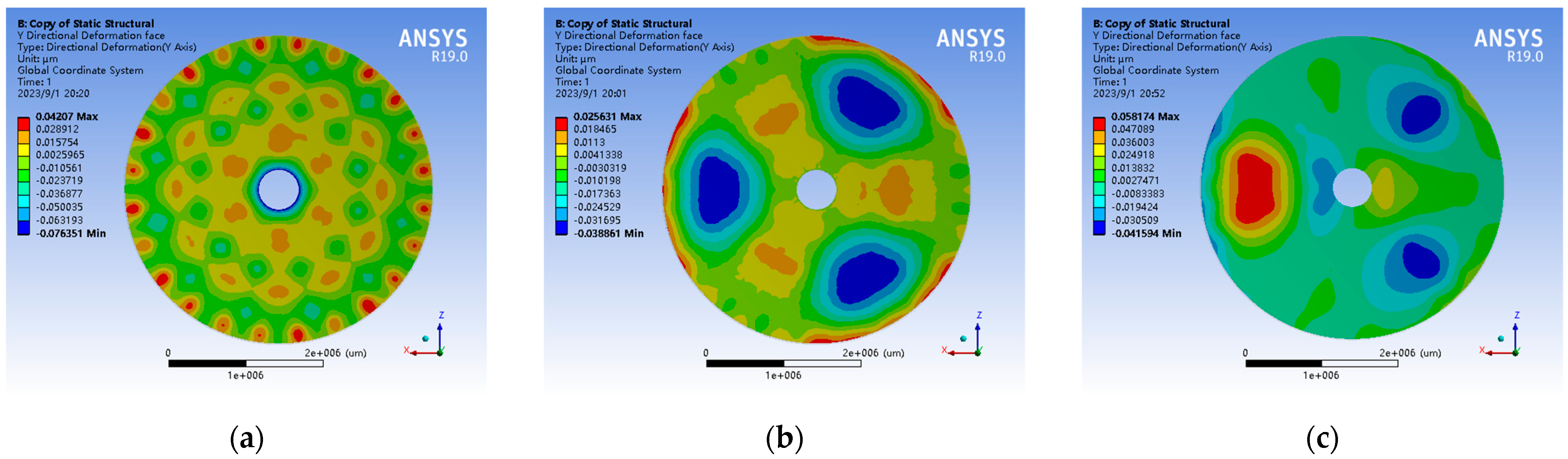
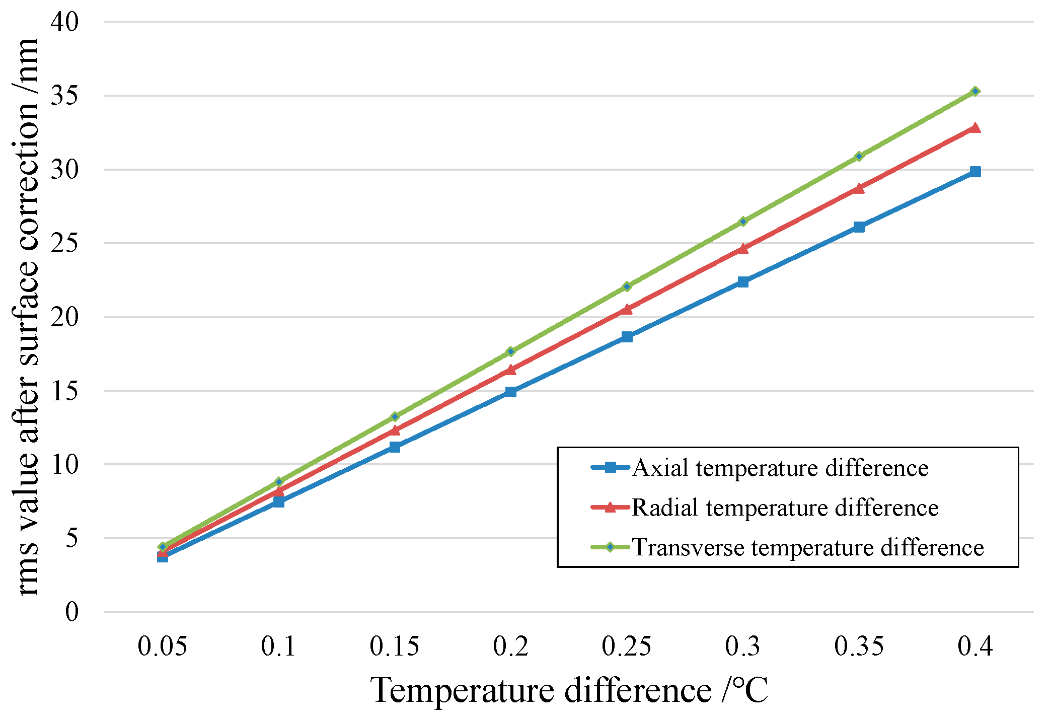
4.4.1. Thermal Load
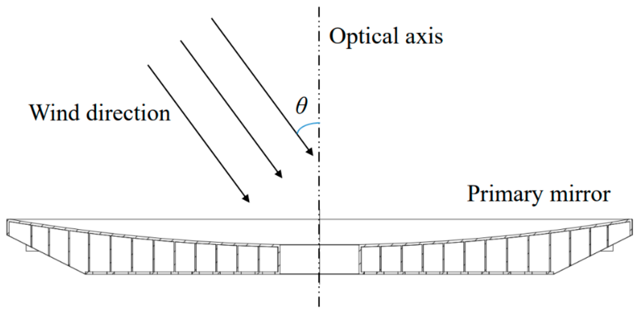
4.4.2. Wind Load
5. Conclusions
Author Contributions
Funding
Institutional Review Board Statement
Informed Consent Statement
Data Availability Statement
Conflicts of Interest
References
- Wilson, R.N.; Franza, F.; Noethe, L. Active Optics I. A System for Optimizing the Optical Quality and Reducing the Costs of Large Telescopes. J. Mod. Opt. 1987, 4, 485–509. [Google Scholar] [CrossRef]
- Noethe, L.; Franza, F.; Giordano, P.; Wilson, R.N.; Citterio, O.; Conti, G.; Mattaini, E. Active Optics II. Results of an Experiment with a Thin 1 m Test Mirror. J. Mod. Opt. 1988, 35, 1427–1457. [Google Scholar] [CrossRef]
- Wilson, R.N.; Franza, F.; Giordano, P.; Noethe, L.; Tarenghi, M. Active Optics III. Final Results with the 1 m Test Mirror and NTT 3·58 m Primary in the Workshop. J. Mod. Opt. 1989, 36, 1415–1425. [Google Scholar] [CrossRef]
- Wilson, R.N.; Franza, F.; Noethe, L.; Andreoni, G. Active Optics IV. Set-up and Performance of the Optics of the ESO New Technology Telescope (NTT) in the Observatory. J. Mod. Opt. 1991, 38, 219–243. [Google Scholar] [CrossRef]
- Xu, J.; Li, W.; Wang, K.; Hao, Q.; Lin, G. Design of a 2 m Primary Mirror Assembly Considering Fatigue Characteristics. Appl. Sci. 2022, 12, 10326. [Google Scholar] [CrossRef]
- Muller, G.P.; Hileman, E.A.; Daruich, F.; Warner, M.; Wiecha, O.M.; Araujo, C.; Mills, N.G.; Johnson, B.E.; Stover, E.; Booth, M.T.; et al. LSST M1M3 figure actuator final design, fabrication, and test. Proc. SPIE 2018, 11703, 11703V. [Google Scholar] [CrossRef]
- Tarenghi, M.; Wilson, R.N. The ESO NTT (New Technology Telescope): The First Active Optics Telescope. Proc. SPIE 1989, 1114, 302–313. [Google Scholar] [CrossRef]
- Schipani, P.; Noethe, L.; Magrin, D.; Kuijken, K.; Arcidiacono, C.; Argomedo, J.; Capaccioli, M.; Dall’Ora, M.; D’Orsi, S.; Farinato, J.; et al. Active optics system of the VLT Survey Telescope. Appl. Opt. 2016, 55, 1573–1583. [Google Scholar] [CrossRef] [PubMed]
- Minowa, Y.; Takato, N.; Iwata, I.; Hattori, T. An overview of current and future instrumentation at the Subaru telescope. Proc. SPIE 2016, 9908, 990806. [Google Scholar] [CrossRef]
- Neufeld, C.; Zolcinski-Couet, M.C.; Keane, M.; Ruthven, G. The active primary mirror assembly for the SOAR telescope. Proc. SPIE 2004, 5489, 870–880. [Google Scholar] [CrossRef]
- Vigil, M.L.; Witte, D.J.; LeVan, P.D.; Wallentine, P.J.; Briscoe, D.E.; Anderson, D.L. Sensor suite for the Advanced Electro-Optical System (AEOS) 3.6-m telescope. Proc. SPIE 1996, 2819, 151–169. [Google Scholar] [CrossRef]
- Huedepohl, G.; Tamai, R.; Ehrenfeld, G.; Stranghellini, S.; Kraus, M. Integration and handling of the VLT primary and secondary mirror systems. Proc. SPIE 2000, 4004, 457–470. [Google Scholar] [CrossRef]
- Huang, E. Gemini primary mirror cell design. Proc. SPIE 1997, 2871, 151–169. [Google Scholar] [CrossRef]
- Williams, G.G.; Ortiz, R.; Goble, W.; Gibson, J.D. The 6.5-m MMT Telescope: Status and plans for the future. Proc. SPIE 2016, 9906, 99060V. [Google Scholar] [CrossRef]
- Crass, J.; Bechter, A.; Sands, B.; King, D.L.; Ketterer, R.; Engstrom, M.; Hamper, X.; Kopon, D.; Smous, J.; Crepp, J.R.; et al. Final design and on-sky testing of the iLocater SX acquisition camera: Broad-band single-mode fibre coupling. Mon. Not. R. Astron. Soc. 2021, 501, 2250–2267. [Google Scholar] [CrossRef]
- Meeks, R.L.; Ashby, D.; Biddick, C.; Devries, J.; Gusick, M.; Kern, J. Super hardpoints for the Large Binocular Telescope. Proc. SPIE 2010, 7733, 77335H. [Google Scholar] [CrossRef]
- Neill, D.; Angeli, G.; Claver, C.; Hileman, E.; DeVries, J.; Sebag, J.; Xin, B. Overview of the LSST active optics system. Proc. SPIE 2014, 9150, 91500G. [Google Scholar] [CrossRef]
- Yin, J.E.; Eisenstein, D.J.; Finkbeiner, D.P.; Stubbs, C.W.; Wang, Y. Active Optical Control with Machine Learning: A Proof of Concept for the Vera C. Rubin Observatory. Astron. J. 2021, 161, 216. [Google Scholar] [CrossRef]
- Schipani, P.; D’Orsi, S.; Ferragina, L.; Fierro, D.; Marty, L.; Molfese, C.; Perrotta, F. Active optics primary mirror support system for the 2.6m VST telescope. Appl. Opt. 2010, 49, 1234–1241. [Google Scholar] [CrossRef]
- Li, W.; Tang, J.; Guo, Y.; Rao, C. Active correction experiments on a 4-m thin primary mirror. Opt. Express 2021, 29, 41920–41931. [Google Scholar] [CrossRef]
- Wang, H.; Zuo, Y.; Zheng, X.; Yang, J. Free-vibration modes of an annular mirror for the optical aberration representation. J. Astron. Telesc. Instrum. Syst. 2019, 5, 024002. [Google Scholar] [CrossRef]
- Wang, H.; Liang, M.; Yao, D.; Zuo, Y.; Zheng, X.; Yang, J. Study on the application of the freevibration modes of an annular mirror in the active optics system. J. Astron. Telesc. Instrum. Syst. 2020, 6, 019002. [Google Scholar] [CrossRef]
- Martin, H.M.; Davison, W.B.; DeRigne, S.T.; Hill, J.M.; Hille, B.B.; Meeks, R.L.; Trebisky, T.J. Active supports and force optimization for a 3.5-m honeycomb sandwich mirror. Proc. SPIE 1994, 2119, 251–262. [Google Scholar] [CrossRef]
- Li, W.; Tang, J.; Guo, Y.; Rao, C. Constrained least-squares algorithm for active optics correction of a primary mirror. Appl. Opt. 2022, 61, 108–114. [Google Scholar] [CrossRef]
- Martin, H.M.; Callahan, S.P.; Cuerden, B.; Davison, W.B.; DeRigne, S.T.; Dettmann, L.R.; Parodi, G.; Trebisky, T.J.; West, S.C.; Williams, J.T. Active supports and force optimization for the MMT primary mirror. Proc. SPIE 1998, 3352, 412–423. [Google Scholar] [CrossRef]
- Martin, H.M.; Cuerden, B.; Dettmann, L.R.; Hill, J.M. Active optics and force optimization for the first 8.4-m LBT mirror. Proc. SPIE 2004, 5489, 826–837. [Google Scholar] [CrossRef]
- Lan, B.; Wu, X.; Li, J.; Ming, M.; Liu, X.; Yang, H. Influence of axial-force errors on the deformation of the 4 m lightweight mirror and its correction. Appl. Opt. 2017, 56, 611–619. [Google Scholar] [CrossRef]
- Yu, Z.; Wu, X.; Wang, F. Optimal design of parameters of the six-hardpoint positioning mechanism for large aperture primary mirror. Opt. Precis. Eng. 2023, 31, 200–213. [Google Scholar] [CrossRef]
- Yu, Z.; Wu, X.; Wang, F. Kinematic Calibration Method for Six-Hardpoint Positioning Mechanisms Using Optimal Measurement Pose. Appl. Sci. 2023, 13, 4824. [Google Scholar] [CrossRef]
- Qu, Y.; Jiang, Y.; Feng, L.; Li, X.; Liu, B.; Wang, W. Lightweight Design of Multi-Objective Topology for a Large-Aperture Space Mirror. Appl. Sci. 2018, 8, 2259. [Google Scholar] [CrossRef]
- Greenhalgh, R.J.S.; Stepp, L.M.; Hansen, E.R. Gemini primary mirror thermal management system. Proc. SPIE 1994, 2199, 911–921. [Google Scholar] [CrossRef]
- Hermann, K.G.; Finley, D.S.; Gienger, A. High-performance mount for the SOAR telescope project. Proc. SPIE 2000, 4004, 127–134. [Google Scholar] [CrossRef]
- Smith, D.R.; Avitabile, P.; Gwaltney, G.; Cho, M.; Sheehan, M. Wind-induced structural response of a large telescope. Proc. SPIE 2004, 5495, 258–269. [Google Scholar] [CrossRef]
- Noethe, L. Active optics in modern large optical telescopes. Prog. Opt. 2002, 43, 1–69. [Google Scholar] [CrossRef]
- MacMynowski, D.G.; Vogiatzis, K.; Angeli, G.Z.; Fitzsimmons, J.; Nelson, J.E. Wind loads on ground-based telescopes. Appl. Opt. 2006, 45, 7912–7923. [Google Scholar] [CrossRef]
- Zhang, J.C.; Ge, L.; Lu, X.M.; Cao, Z.H.; Chen, X.; Mao, Y.N.; Jiang, X.J. Astronomical Observing Conditions at Xinglong Observatory from 2007 to 2014. Publ. Astron. Soc. Pac. 2015, 127, 1292–1306. [Google Scholar] [CrossRef]


| Number of Hardpoints | Elevation Angle of 45° | Elevation Angle of 90° | ||||
|---|---|---|---|---|---|---|
| dx/μm | dy/μm | dz/μm | dx/μm | dy/μm | dz/μm | |
| 1 | −6.37 | 0.96 | −13.77 | −1.86 | 1.41 | −19.54 |
| 2 | −6.36 | −1.04 | −13.74 | −1.61 | −0.39 | −18.92 |
| 3 | −5.00 | −1.72 | −17.00 | −0.67 | −1.06 | −19.79 |
| 4 | −3.96 | −0.30 | −22.35 | 0.88 | −0.05 | −19.66 |
| 5 | −3.97 | 0.23 | −22.53 | 0.87 | 1.01 | −19.55 |
| 6 | −5.01 | 1.63 | −17.13 | −0.77 | 2.17 | −19.86 |
| Force | Direction of Force | Role of Force | Number of the Actuator i | Value of Force/N |
|---|---|---|---|---|
| FFZi | z | Compensate for FZ | 1–30 | FZ/30 |
| FFXi | x | Compensate for FX | 1–18, 20–23, 26–29 | FX/26 |
| FFYi | y | Compensate for FY | 19, 24, 25, 30 | FY/4 |
| FMXi | z | Compensate for MX | 1–30 | |
| FMYi | z | Compensate for MY | 1–30 | |
| FMZi | y | Compensate for MZ | 19, 24, 25, 30 |
| Elevation Angle | Primary Mirror Surface Shape rms/nm | Amplitude of the Correction Force/N | Maximum Von Mises Stress of the Primary Mirror/MPa | |
|---|---|---|---|---|
| Before Calibration | After Correction | |||
| 90° | 64.8 | 14.8 | 51.3 | 0.51 |
| 45° | 165.3 | 14.5 | 59.6 | 0.96 |
| 0° | 211.0 | 15.8 | 57.2 | 1.18 |
| Temperature Field | Primary Mirror Surface Shape rms/nm | Amplitude of the Correction Force/N | Maximum Von Mises Stress of the Primary Mirror/MPa | |
|---|---|---|---|---|
| Before Calibration | After Correction | |||
| Axial temperature difference of 0.2 °C | 1026.7 | 14.9 | 303.8 | 0.34 |
| Radial temperature difference of 0.2 °C | 196.2 | 16.4 | 60.7 | 0.15 |
| Transverse temperature difference of 0.2 °C | 58.7 | 17.7 | 125.3 | 0.15 |
| θ | Primary Mirror Surface Shape rms/nm | Amplitude of the Correction Force/N | Maximum Von Mises Stress of the Primary Mirror/MPa | |
|---|---|---|---|---|
| Before Calibration | After Correction | |||
| 0° | 741.2 | 1.8 | 596.0 | 0.061 |
| 30° | 656.3 | 1.6 | 631.3 | 0.092 |
| 60° | 440.4 | 1.6 | 522.9 | 0.126 |
Disclaimer/Publisher’s Note: The statements, opinions and data contained in all publications are solely those of the individual author(s) and contributor(s) and not of MDPI and/or the editor(s). MDPI and/or the editor(s) disclaim responsibility for any injury to people or property resulting from any ideas, methods, instructions or products referred to in the content. |
© 2023 by the authors. Licensee MDPI, Basel, Switzerland. This article is an open access article distributed under the terms and conditions of the Creative Commons Attribution (CC BY) license (https://creativecommons.org/licenses/by/4.0/).
Share and Cite
Yu, Z.; Wu, X.; Wang, F. Active Support System for the Correction of a 4m SiC Primary Mirror Based on the Bending Mode. Appl. Sci. 2023, 13, 9966. https://doi.org/10.3390/app13179966
Yu Z, Wu X, Wang F. Active Support System for the Correction of a 4m SiC Primary Mirror Based on the Bending Mode. Applied Sciences. 2023; 13(17):9966. https://doi.org/10.3390/app13179966
Chicago/Turabian StyleYu, Zhiyuan, Xiaoxia Wu, and Fuguo Wang. 2023. "Active Support System for the Correction of a 4m SiC Primary Mirror Based on the Bending Mode" Applied Sciences 13, no. 17: 9966. https://doi.org/10.3390/app13179966
APA StyleYu, Z., Wu, X., & Wang, F. (2023). Active Support System for the Correction of a 4m SiC Primary Mirror Based on the Bending Mode. Applied Sciences, 13(17), 9966. https://doi.org/10.3390/app13179966