Abstract
The traditional A* and DWA fusion algorithm has three problems in the task of aggregation formation: one is the lack of meeting coordination strategy, the other is the inability to unify the terminal course, and the third is too many turning points in the global path. To solve the above problems, an improved algorithm is proposed. Firstly, by smoothing the global planning path, the stability of a USV heading in the navigation is improved. Then, by adding the key points of the global path, a guide path is formed to unify the terminal heading range. Finally, by adding an encounter coordination strategy, aggregation efficiency is improved. Simulation experiments were carried out in the Python environment based on this algorithm. The results show that the improved algorithm can improve the navigation obstacle avoidance ability of USVs and guide multiple USVs to finish the task of aggregation formation.
1. Introduction
In contrast to manned ships, unmanned surface vessels (USVs) have been widely used as a new type of unmanned maritime platform in many fields such as marine observation, hydrographic survey, and accident search and rescue, leading to innovative changes. The unmanned platform at sea has greatly promoted the transition of the ship industry in the direction of informatization and unmanned intelligence. Gradually, USVs are replacing manned ships as the backbone in some fields. As an important development in unmanned technology, USV formation provides advantages in terms of lower cost, higher safety, stronger task adaptability, mutual synergy, and stronger data processing capabilities compared with single-boat manned ships. First, USV formation does not need to carry personnel, which can save expenses related to personnel life support, thereby greatly reducing the cost of the formation. Second, USVs are more flexible in dealing with a variety of complex environments. Under harsh maritime working conditions, the safety of the USV equipment is the only consideration, and there are no additional personnel adaptability and personal safety concerns. Third, the form and number of USV formations can be selected according to the requirements of the task to quickly adapt and respond to different task requirements. Fourth, USV formations can realize cooperative control through intelligent technology, and with higher formation synergy, the efficiency of mission execution can further be improved. Fifth, USV formations can carry more types of sensors and data acquisition equipment, allowing the collection, processing, and transmission of a large amount of data in real time, thereby providing support for more efficient and accurate mission execution.
In USV navigation control formation, path planning and obstacle avoidance technologies are the keys to intelligent navigation. Obstacle avoidance technology is essential in ensuring the safe and efficient navigation of a USV, and path planning technology can generate efficient and feasible trajectories based on the information collected by various sensors and communication systems, whereby according to a USV’s performance and environmental conditions, the USV is guided to reach the target location safely and accurately. Therefore, the usual method of intelligent navigation employs global path planning algorithms to achieve path planning in a known environment, and subsequently uses local path planning algorithms to achieve dynamic obstacle avoidance in a positional environment. The common global path planning algorithms include the reverse encryption algorithm (REA)* based on a grid map [1], A*, Dijkstra, and randomly exploring random tree (RRT)* algorithms based on the sampling method [2], as well as a probabilistic roadmap (PRM) and intelligent AG based on neural networks and ant colony algorithms [3,4]. Local path planning algorithms include the artificial potential field method (PFM), dynamic window approach (DWA), time elastic band (TEB) [5], and vector field histogram (VFH) algorithms [6]. In integrating the above global and local path planning algorithms, the A* algorithm provides the advantages of easy implementation, wide applicability, and strong scalability, whereas DWA can fully combine the underactuated characteristics of USV and displays stronger adaptability. Therefore, the two were selected as the ideal global and local path planning algorithms for fusion to achieve ideal results in autonomous navigation applications.
In the literature, Chen et al. [7] used the key turning point extraction algorithm to eliminate redundant inflection points and redundant nodes in the global path, optimized the traditional A* algorithm, and fused it with DWA to optimize path length, smoothness, and safety. Lao et al. [8] improved the key point selection strategy based on the traditional A* algorithm and fused it with DWA to construct a global optimal path evaluation function to achieve real-time optimal path planning. Li et al. [9] validated and analyzed the A* and DWA fusion algorithm for a single USV. Zhan et al. [10] introduced the safety distance factor into the heuristic function of the A* algorithm to improve the safety of the algorithm’s planned path and subsequently used the planar structure method to smooth and optimize the global planned path to realize the path planning of the A* and DWA fusion algorithm. Liu et al. [11] quantified and analyzed the obstacle information in the environment, thereby adjusting the weights of the heuristic function of the A* algorithm to improve algorithmic efficiency and flexibility. In addition, they improved the path smoothing based on Floyd’s algorithm to realize dynamic path planning in complex environments. Lu et al. [12] optimized the predicted cost function and heuristic function of the A* algorithm to tune the global planning path to the requirements of the task. Zhao et al. [13] reduced the turn angle for path planning in the improved A* algorithm by treating travel time as the cost and adjusting the weight of the heuristic function according to obstacle information. Bian et al. [14] incorporated the key track points in the global planning path of A* into the evaluation function of the DWA algorithm to solve the problem of the traditional DWA algorithm which fails to evaluate under a combination of “C”-shaped obstacles, and improved the ability to navigate through dense obstacle zones. Wu et al. [15] proposed a hybrid dynamic path planning algorithm for FAGV based on improved A* and improved DWA. This algorithm can avoid obstacles dynamically without being far away from the global optimal path. Dan et al. [16] proposed the improved A* algorithm combined with the greedy algorithm for a multi-objective path planning strategy. This algorithm can achieve a smoother path and reduce the path length by about 5%. Bai et al. [17] proposed a path planning algorithm based on A* and DWA to achieve global path optimization while satisfying security and speed requirements for unmanned aerial vehicles (UAVs). This algorithm shortens the path length, reduces the planning time, improves the smoothness of the UAV path, and enhances the safety of UAV path obstacle avoidance. R. Han et al. [18] proposed a distributed approach for multi-robot navigation which combines the concept of reciprocal velocity obstacle (RVO) and the scheme of deep reinforcement learning (DRL) to solve the reciprocal collision avoidance problem with limited information.
The above research indicates various application directions for the A* and DWA fusion algorithm, mostly focusing on the path planning of a single intelligent body, and less on aggregation formation-related problems such as collaborative path planning of multi-intelligent bodies and cross-encounters. In USV aggregation formation, the traditional A* and DWA fusion algorithm is not applicable to this scenario for the following reasons. First, the global path ramp of the traditional A* algorithm has numerous turning points, which causes the USVs to jitter in the local path planning stage. Second, the USVs are under-driven models, and the traditional fusion algorithm cannot unify the heading range of the USVs when arriving at the end point, which forms a certain obstacle to the cooperative movement after aggregation formation. Third, the intersection of multiple USV paths is not considered because of a lack of an encounter coordination strategy, which can easily lead to collision accidents or reduce obstacle avoidance efficiency. Therefore, this study improves the traditional A* and DWA algorithms to address the three aforementioned problems. The algorithm is improved and optimized by smoothing the global planning path, specifying the end position heading range, and adding an encounter coordination strategy to make it suitable for USV aggregation formation.
In this paper, Section 1 mainly analyzes the importance of USV navigation control research and introduces the research status of USV navigation and formation assembly. Section 2.1 mainly expounds on the traditional A* and DWA fusion algorithm. Section 2.2 mainly introduces the main contents of the improved algorithm. Section 2.2 and Section 2.3 mainly introduces the main contents of the improved algorithm. Section 3 mainly carries out simulation experiments and comparative analysis. Section 4 mainly summarizes the findings and future prospects.
2. Materials and Methods
2.1. Overview of Traditional A* and DWA Algorithms
2.1.1. Traditional A* Algorithm
The traditional A* algorithm, proposed by Hart et al. [19], is a heuristic search algorithm that finds the shortest path to the target location in a graph. This algorithm is optimized on the basis of Dijkstra’s algorithm; however, compared to Dijkstra’s algorithm, a cost function is introduced to optimize the search process by reducing the number of nodes, thereby improving search efficiency. The basic idea of the A* algorithm is to start from the starting point, calculate for each node the cost to the starting point and to the end point , and then add the two values to obtain . Commencing with the starting point, the node with the smallest value of is selected for extended traversal until the end point is reached, or OPENLIST is empty. The cost function is expressed as
In Equation (1), the heuristic function is one of the most important factors affecting the temporal complexity of the A* algorithm [20]. The specific flow of the traditional A* algorithm is shown in Figure 1.
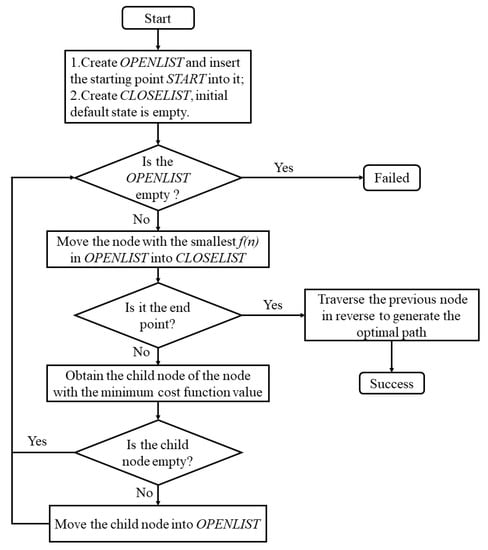
Figure 1.
Flowchart of algorithm A*.
2.1.2. Traditional DWA Algorithm
The traditional DWA algorithm, proposed by Fox et al. [21], obtains a feasible velocity combination within a certain time window by combining the limiting velocity and acceleration constraints of the robot’s own physical limitations with the obstacle constraints of the object environment , where and denote linear and angular velocities, respectively. The three types of constraints can be expressed as follows:
where is the self-limiting velocity constraint; is the self-limiting acceleration constraint; is the obstacle constraint; denotes the current linear velocity; denotes linear acceleration; is the current angular velocity; is angular acceleration; denotes the distance between the trajectory and the nearest obstacle.
The intersection of the three types of constraints determines the feasible velocity range:
By sampling all feasible velocity combinations according to the specified accuracy , the predicted trajectory is formed and evaluated, and the one with the highest score is considered the ideal trajectory. The evaluation function is defined as follows:
where , , are the weight coefficients; the function refers to the difference between the heading angle at the end of the trajectory and the azimuth angle of the target; the function calculates the distance between the target and the nearest obstacle; the function is the linear velocity magnitude; denotes the normalization process.
2.1.3. Traditional A* and DWA Fusion Algorithm
The traditional A* and DWA fusion algorithm can simultaneously consider the global static environment as well as the layout dynamic environment. The USV relies on the map resources pre-loaded into the database and its own sensors to develop situational awareness of the global and local environments. The global optimal path is first obtained according to the A* algorithm, whereby the optimal path is discretized into a number of point traces. Subsequently, the locally optimal path is generated according to the target point of the DWA algorithm, as determined by the point traces, and combined with the location of surrounding obstacles to generate navigational information to guide the USV. The fusion algorithm can continuously update the heading state of the USV, considering the navigational capability constraints and environmental information, thus achieving more efficient and accurate path planning. The algorithmic principle is illustrated in Figure 2.
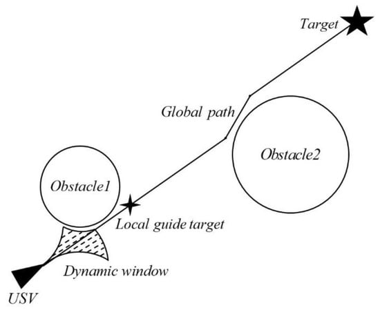
Figure 2.
Traditional A* and dynamic window fusion algorithm.
In Figure 2, the global path is first generated using the traditional A* algorithm based on the position, size, and other information on the USV target and obstacles in the environment. Then, the local guide target is set according to the distance from the USV and used as the target point for the DWA algorithm. Finally, the traditional DWA algorithm is used to generate the dynamic window and guide the navigation.
2.2. Global Path Smoothing Optimization
2.2.1. Problems with the Global Path of the Traditional A* Algorithm
The traditional A* algorithm grids the global environment and explores the surrounding grids, starting to traverse from the grid where the target is located. As shown in Figure 3, in the traditional algorithm, there are mainly four or eight directions for traversal search. However, the complexity of the actual global environment is much higher; therefore, even if the eight-direction search algorithm is used, the calculated global path is only composed of continuous line segments in eight directions, making it difficult to satisfy the requirements of the actual environment. When other angular directions appear, the traditional A* algorithm combines them according to the existing directions, thereby causing additional turning points to appear in the generated paths. This increases the complexity of the global path and affects the stability and accuracy of the navigation phase of the USV.
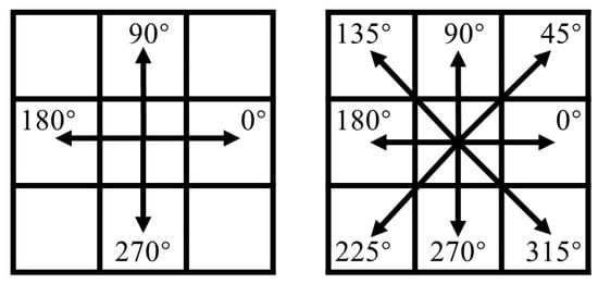
Figure 3.
Traversal search of traditional A* algorithm.
2.2.2. Improved Path Smoothing
To eliminate the extra turning points in the paths and achieve simplified global paths, a path smoothing algorithm is proposed in this study. Based on the paths obtained by the traditional A* algorithm, the non-essential path points are eliminated, and the critical path points are retained to obtain smoothed and optimized critical paths. The specific steps of this algorithm are shown in Figure 4 below. After eliminating the non-essential path points, the number of points in the optimized path set is reduced. In subsequent steps of the fusion algorithm, optimized global paths are collected and added to the path point set according to the unit grid length of the A* algorithm.
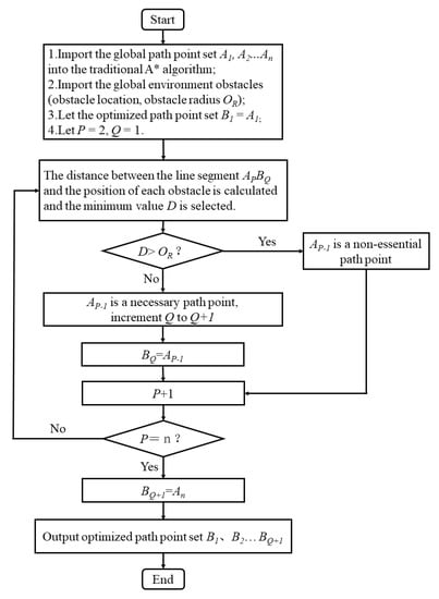
Figure 4.
Flowchart of improved path smoothing algorithm.
2.3. Designated End Position Heading
2.3.1. Traditional Fusion Algorithm Endpoint Position Heading
In the traditional fusion algorithm, the heading at the end point of the USV is determined by environmental obstacles and the global path. The A* algorithm only provides the optimal solution for reaching the end point from the starting point. Moreover, the traditional DWA algorithm cannot realize the function of customizing the end point heading, and the method of modifying the path evaluation index function is complex and difficult to realize. As shown in Figure 5, in an ideal environment without obstacles, regardless of the value of the USV heading angle at the starting position, the end point heading of the USV, determined by the traditional fusion algorithm, always converges to the end point azimuth of the starting position, and the longer the global path length, the smaller the difference between the two angles . Therefore, the terminal heading of the USV is always determined by the azimuth angle , which is affected by the global path length.
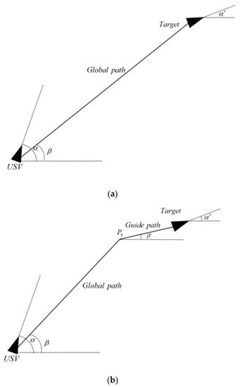
Figure 5.
(a). USV heading and end point bearing. (b). Global path end point guidance section added.
2.3.2. Adding a Global Path End Point Guide Segment
A method is proposed in this study to realize the control of the end point heading of the USV, whereby a key waypoint is set on the basis of the global path obtained by the traditional A* algorithm to form a global path end point guidance section. The guidance section is the line between the key waypoint and the target point, and the azimuth of the key waypoint at the end point is the reference value of the end point heading control. Thus, the longer the length of the guidance section, the smaller the error value . Therefore, the length of the guidance section and the azimuth angle can be adjusted to achieve control of the end point heading of the USV.
2.4. Synergistic Optimization of Multi-USV Encounters
2.4.1. Encounter Problems in the Traditional Fusion Algorithm
The traditional fusion algorithm is designed to solve the single USV navigation problem. In a multi-USV environment, the algorithm achieves the desired effect only when the global paths of each USV do not cross and maintain a considerable distance from each other. In scenarios involving encounters, it is difficult to complete safe and efficient navigation tasks using the traditional fusion algorithm.
2.4.2. Encounter Coordination Strategy for Multiple USVs
To solve the encounter problem in multi-USV navigation, an encounter coordination strategy is proposed. First, an encounter judgment rule is set such that when the distance between the local guidance points of each USV is less than or equal to a specified value, the USVs are judged to be in an encounter situation. Second, the priority of USV maneuvering is set to avoid a collision. The USVs considered to be in a mutual encounter situation are grouped, and the outboard angle value of the current USV relative to another USV is calculated, whereby the USV with the larger outboard angle value is given higher priority to avoid a collision. Finally, according to the priority level, the local guidance point of each USV is adjusted, only keeping the local guidance point position of the low-priority USV unchanged, and the current position of the other USV is incorporated into the global environment of the high-priority USV as the midpoint of the obstacle. At this time, the low-priority USV gradually decelerates to the local guidance point, and the high-priority USV maneuvers rapidly toward the global target point to ensure navigation safety. The process continues until the distance between the two local guidance points is greater than the critical value, at which point the encounter situation is circumvented, and the low-priority USV resumes movement from the local target point, continuing to guide the USV while gradually accelerating.
As shown in Figure 6, when the distance between USV1 and USV2′s local guidance point reaches the critical value, the outboard angle values are compared, and if , USV2′s collision avoidance priority is higher than that of USV1, whereby USV1 will slow down to the current local guidance point to avoid USV2, and USV2 will sail normally.
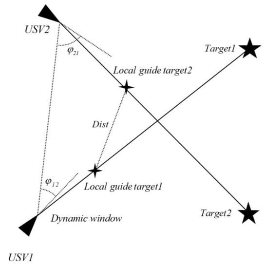
Figure 6.
Encounter coordination strategy for multiple USVs.
3. Experiments and Results
To verify that the improved fusion algorithm can further enhance the USV obstacle avoidance synergy and achieve USV aggregation formation, the traditional fusion and improved algorithms were simulated in the Python environment, and the results were analyzed and compared. The parameters of the USV kinematic and DWA algorithms are shown in Table 1 and Table 2, respectively.

Table 1.
USV kinematic parameters.
Table 2.
Fusion algorithm parameters.
3.1. Global Path Smoothing Verification Experiment
Based on Table 1 and Table 2, a single USV path planning environment containing three obstacles was created, and the traditional A* algorithm was compared with the smoothing optimization algorithm. In Figure 7 and Figure 8, the global path steering points are significantly reduced after smoothing optimization, from 41 to 2 in this scenario, which is a positive outcome of smoothing optimization.
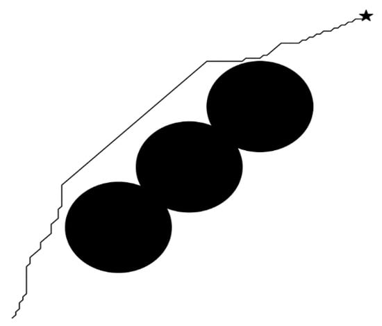
Figure 7.
Global path of traditional A* algorithm.
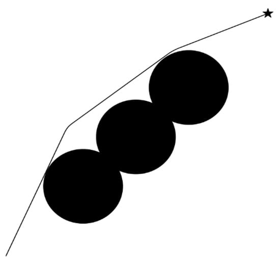
Figure 8.
Global path after smoothing optimization.
3.2. Designated End Position Heading Verification Experiment
The dual-USV path planning environment was created according to Table 1 and Table 2, and the heading control reference of the optimized algorithm was set to 0° in comparing the traditional fusion algorithm with the optimized algorithm, as shown in Figure 9, Figure 10, Figure 11 and Figure 12.
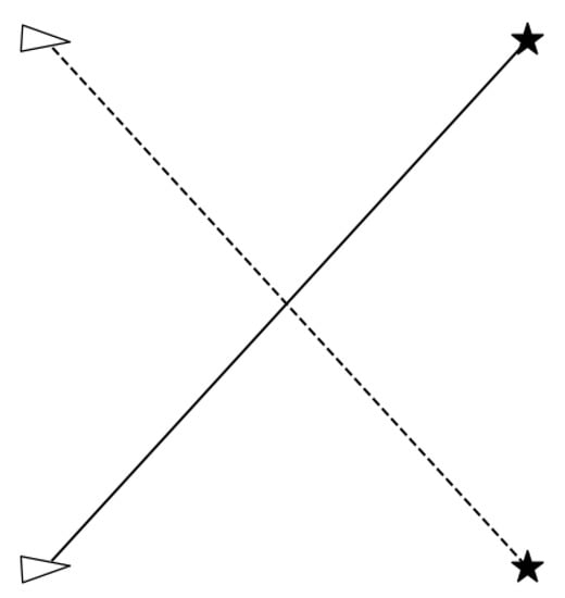
Figure 9.
Global path of traditional A* algorithm.
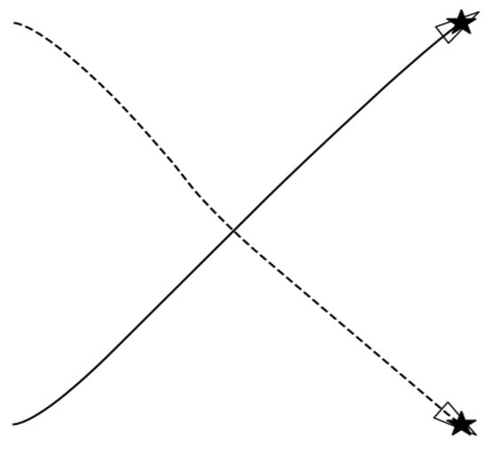
Figure 10.
USV trajectory and end position heading of traditional fusion algorithm.
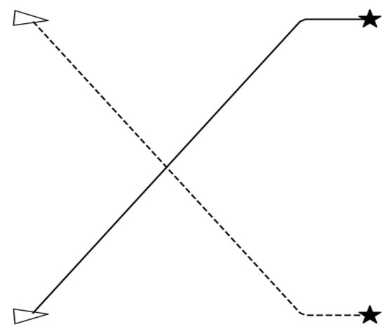
Figure 11.
Global path of optimized algorithm.
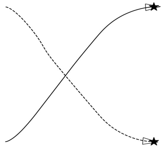
Figure 12.
USV trajectory and end position heading of optimized fusion algorithm.
3.3. Validation Experiment for Encounter Coordination
Based on Table 1 and Table 2, a dual-USV environment was created, and USV head-on encounter and cross-encounter situations were set up to compare the traditional fusion algorithm and the optimized algorithm with an encounter coordination strategy, as shown in Figure 13, Figure 14, Figure 15 and Figure 16.

Figure 13.
Dynamic window during traditional algorithm encounter (head-on encounter situation).

Figure 14.
Dynamic window during encounter with optimization algorithm (head-on encounter situation).
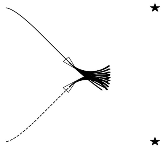
Figure 15.
Dynamic window during traditional algorithm encounter (cross-encounter situation).
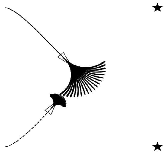
Figure 16.
Dynamic window during optimization algorithm encounter (cross-encounter situation).
In Figure 13, Figure 14, Figure 15 and Figure 16, in the traditional algorithm without an encounter coordination strategy, the use of the DWA algorithm fails to achieve the desired avoidance maneuver in an encounter situation. In the simulation experiment results of Figure 13 and Figure 15, the USVs collide, and the navigation task cannot be completed. In contrast, the optimization algorithm with an encounter coordination strategy provides good safety and applicability by setting the priority of avoidance, thereby allowing one of the USVs to slow down and avoid a collision to achieve safe navigation while also complying with the actual rules of safe maritime navigation. In Figure 17 and Figure 18, under the optimization algorithm, the USV does not take a large angle maneuver during the encounter and can choose an efficient cooperative collision avoidance path with a shorter distance, which allows the USV to economize on fuel in practical situations.
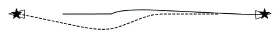
Figure 17.
Optimization algorithm encounter trajectories (cross-encounter situation).
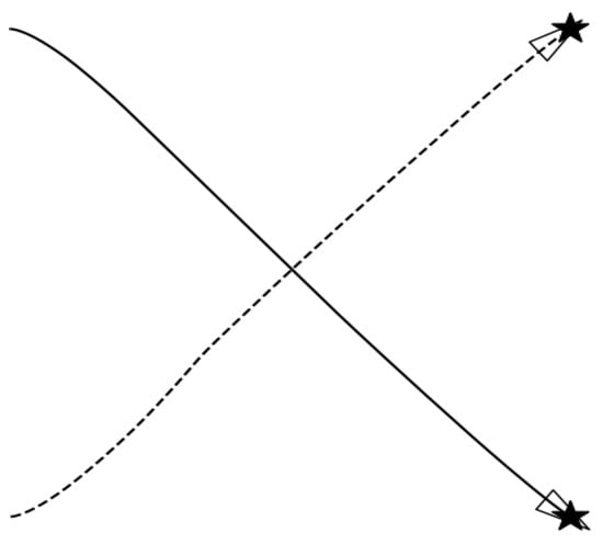
Figure 18.
Optimization algorithm encounter trajectories (cross-encounter situation).
3.4. Multi-USV Aggregation Formation Experiment
According to Table 1 and Table 2, three USV environments were created, and obstacles were added. The reference value of heading control of the optimization algorithm was set, and a simulation experiment was conducted for USV aggregation formation. The results are shown in Figure 19, Figure 20 and Figure 21.
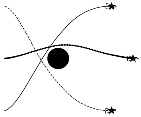
Figure 19.
Simulation of aggregation formation ().
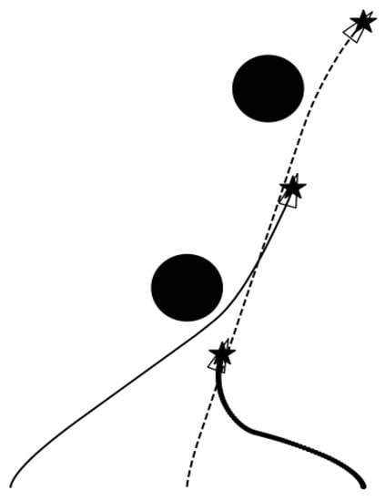
Figure 20.
Simulation of aggregation formation ().
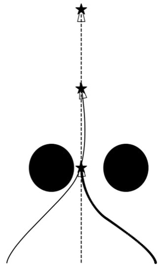
Figure 21.
Simulation of aggregation formation ().
In Figure 19, Figure 20 and Figure 21, it is observed that the optimized algorithm provides significant improvements in obstacle avoidance, encounter, and end course uniformity in the environment of the three USVs, achieving ideal results in the simulation environment, by completing more complicated USV aggregation formation tasks.
Through the above experiments and analysis, the method proposed in Reference [18] is compared with the fusion algorithm in this paper, as shown in Table 3:
Table 3.
Algorithm comparison.
Compared with the method proposed in reference [18], the fusion algorithm in this paper has the following advantages:
- By improving the traditional A* algorithm, this paper realizes the function of specifying the terminal course, which is more comprehensive in formation control ability;
- The algorithm in this paper can be successfully implemented in multi-type environments by setting appropriate parameters. However, the deep reinforcement learning algorithm needs many simulated environments for training, and also needs targeted training according to different types of environments to achieve better results. Therefore, the algorithm proposed in this paper is more adaptable to the environment;
- A deep reinforcement learning algorithm needs a lot of computing power and takes a long time to obtain an ideal training model, which puts higher demands on the equipment configuration involved in the calculation. The algorithm proposed in this paper is based on traditional A* and DWA algorithms, which have lower complexity and less demand for computing power;
- The RVO algorithm itself is prone to heading jitter in the navigation process, which puts forward higher requirements for the robot’s maneuverability, while the DWA algorithm fully considers the robot’s maneuverability and is more suitable for underactuated systems such as USV.
At the same time, the shortcomings of the algorithm in this paper are that the number of robots in the formation is small, and more complex collision avoidance strategies need to be introduced, which puts forward higher requirements for the efficiency of the algorithm and is more difficult to realize.
4. Conclusions
In this paper, we analyzed the traditional A* and DWA fusion algorithm to investigate the problems in the predicted trajectory window during collision avoidance. By smoothing the global planning path, the stability of the USV heading in the navigation stage was improved. Subsequently, global path key points were added to form the end point guidance segment, which can specify the end point location heading range. For the multi-USV encounter coordination problem, the aggregation efficiency and safety were improved by introducing an encounter coordination strategy. The simulation results show that the improved fusion algorithm can better improve the control ability and navigation efficiency of USVs and complete the task of USV aggregation formation.
At the same time, the description of the USV motion model in this algorithm is relatively simple, with a certain divergence from the actual USV motion situation. Moreover, the model of the simulation environment is not rich enough, and there is a lack of a more comprehensive analysis of the efficiency and applicable environment of the algorithm. The above problems will be further improved in the follow-up algorithm improvement and real-scene testing research to obtain more ideal experimental results.
Author Contributions
Conceptualization, G.-A.W. and J.-Q.Z.; validation, G.-A.W. and J.-Q.Z.; writing—original draft preparation, G.-A.W.; writing—review and editing, J.-Q.Z. All authors have read and agreed to the published version of the manuscript.
Funding
This research received no external funding.
Institutional Review Board Statement
Not applicable.
Informed Consent Statement
Not applicable.
Data Availability Statement
Not applicable.
Conflicts of Interest
The authors declare no conflict of interest.
References
- Zhang, A.; Li, C.; Bi, W. Rectangle expansion A* pathfinding for grid maps. Chin. J. Aeronaut. 2016, 29, 1385–1396. [Google Scholar] [CrossRef]
- Qureshi, A.H.; Ayaz, Y. Potential functions based sampling heuristic for optimal path planning. Auton. Robot. 2016, 40, 1079–1093. [Google Scholar] [CrossRef]
- Liu, C.-A.; Yan, X.-H.; Liu, C.-Y.; Wu, H. A dynamic path planning method for mobile robots based on improved ant colony algorithm. J. Electron. 2011, 39, 1220–1224. [Google Scholar]
- Xiaoyan, W.; Yang, L.; Zhang, Y.; Meng, S. Robot path planning based on improved potential field ant colony algorithm. Control. Decis. Mak. 2018, 33, 1775–1781. [Google Scholar] [CrossRef]
- Roesmann, C.; Feiten, W.; Woesch, T.; Hoffmann, F.; Bertram, T. Trajectory Modification Considering Dynamic Constraints of Autonomous Robots. In Proceedings of the 7th German Conference on Robotics (ROBOTIK 2012), Munich, Germany, 21–22 May 2012; pp. 1–6. [Google Scholar]
- Statheros, T.; Howells, G.; McDonald-Maier, K. Autonomous ship collision avoidance navigation concepts, technologies and techniques. J. Navig. 2008, 61, 129–142. [Google Scholar] [CrossRef]
- Chen, J.; Xu, L.; Chen, J.; Liu, Q. Improved A~* and dynamic window method for mobile robot path planning. Comput. Integr. Manuf. Syst. 2022, 28, 1650–1658. [Google Scholar] [CrossRef]
- Lao, C.; Li, P.; Feng, Y. Greenhouse robot path planning based on improved A~* and DWA algorithm fusion. J. Agric. Mach. 2021, 52, 14–22. [Google Scholar]
- Li, W.G.; Wang, L.; Fang, D.X.; Li, Y.W.; Huang, X. Oint A~* and dynamic window method for path planning algorithm. Syst. Eng. Electron. Technol. 2021, 43, 3694–3702. [Google Scholar]
- Zhan, W.; Huang, Y.Q. Robot path planning by fusing secure A* algorithm with dynamic windowing method. Comput. Eng. 2022, 48, 105–112+120. [Google Scholar] [CrossRef]
- Liu, J.; Xue, L.; Zhang, H.; Liu, Z. Fusing improved A~* and DWA algorithms for dynamic path planning of robots. Comput. Eng. Appl. 2021, 57, 73–81. [Google Scholar]
- Lu, X.; Wu, C.; Yang, G.; Zhang, B.; Chen, Z. Improved A* and DWA Algorithms for Path Planning of Orchard Spraying Robots. Computer Engineering and Applications 1–8. Available online: http://kns.cnki.net/kcms/detail/11.2127.TP.20221125.1958.036.html (accessed on 18 May 2023).
- Zhao, J.; Zhao, T.; Feng, Y.; Cao, Z.; Zhong, Y. Research on robot path planning based on improved A~* algorithm and DWA fusion. Exp. Technol. Manag. 2023, 40, 87–92. [Google Scholar] [CrossRef]
- Bian, Y.M.; Ji, P.C.; Zhou, Y.H.; Yang, M. Improved DWA-based obstacle avoidance path planning for mobile robots. Chin. J. Eng. Mach. 2021, 19, 44–49. [Google Scholar] [CrossRef]
- Wu, B.; Chi, X.; Zhao, C.; Zhang, W.; Lu, Y.; Jiang, D. Dynamic Path Planning for Forklift AGV Based on Smoothing A* and Improved DWA Hybrid Algorithm. Sensors 2022, 22, 7079. [Google Scholar] [CrossRef] [PubMed]
- Xiang, D.; Lin, H.; Ouyang, J.; Huang, D. Combined improved A* and greedy algorithm for path planning of multi-objective mobile robot. Sci. Rep. 2022, 12, 13273. [Google Scholar] [CrossRef] [PubMed]
- Bai, X.; Jiang, H.; Cui, J.; Lu, K.; Chen, P.; Zhang, M. UAV Path Planning Based on Improved A* and DWA Algorithms. Int. Aerosp. Eng. 2021, 2021, 4511252. [Google Scholar] [CrossRef]
- Han, R.; Chen, S.; Wang, S.; Zhang, Z.; Gao, R.; Hao, Q.; Pan, J. Reinforcement Learned Distributed Multi-Robot Navigation With Reciprocal Velocity Obstacle Shaped Rewards. IEEE Robot. Autom. Lett. 2022, 7, 5896–5903. [Google Scholar] [CrossRef]
- Hart, P.E.; Nilsson, N.J.; Raphael, B. A Formal Basis for the Heuristic Determination of Minimum Cost Paths. IEEE Trans. Syst. Sci. Cybern. 1968, 4, 100–107. [Google Scholar] [CrossRef]
- Feng, K.; Ji, X.; Yang, X. Application of A* algorithm in self-driving vehicle path planning. Automot. Pract. Technol. 2020, 45, 25–28. [Google Scholar] [CrossRef]
- Fox, D.; Burgard, W.; Thrun, S. The dynamic window approach to collision avoidance. IEEE Robot. Autom. Mag. 1997, 4, 23–33. [Google Scholar] [CrossRef]


Disclaimer/Publisher’s Note: The statements, opinions and data contained in all publications are solely those of the individual author(s) and contributor(s) and not of MDPI and/or the editor(s). MDPI and/or the editor(s) disclaim responsibility for any injury to people or property resulting from any ideas, methods, instructions or products referred to in the content. |
© 2023 by the authors. Licensee MDPI, Basel, Switzerland. This article is an open access article distributed under the terms and conditions of the Creative Commons Attribution (CC BY) license (https://creativecommons.org/licenses/by/4.0/).