Abstract
At present, the induction motor (IM), synchronous reluctance motor (SynRM), ferrite-assisted synchronous reluctance motor (ferrite-assisted SynRM) and interior permanent magnet motor (IPM) are research hotspots, but comprehensive comparative research on the four motors is still rare. This paper mainly compares the four motors from the aspects of electromagnetic performance, material cost and temperature distribution. Firstly, the volume of the four motors is ensured to be the same. The influence of the rotor design parameters of the SynRM, ferrite-assisted SynRM and IPM on the electromagnetic properties of the machine is analyzed. Secondly, based on the effects of each parameter, the overall design parameters of the four motors are determined. The electromagnetic performance, material cost and temperature of the four motors are compared and discussed. Finally, the comparison results are summarized, and the advantages of the four motors are analyzed. In different applications, the electromagnetic performance, heat dissipation and cost requirements of the four motors are different. Therefore, this paper makes a comprehensive comparison of the four motors to provide a reference for the selection of motors for different applications.
1. Introduction
Due to the advantages of its robust rotor structure, high torque density and wide speed range, the synchronous reluctance motor (SynRM) has become a research hotspot. But the SynRM has a high torque ripple and low power factor, which limits its development [1,2,3]. Therefore, permanent magnets can be added to the rotor magnetic barrier, which forms a permanent-magnet-assisted synchronous reluctance motor (PMA-SynRM). The permanent magnets can improve its electromagnetic performance, such as its power factor and output torque [4,5,6]. Induction machines (IM) are widely used in industrial and residential applications because of their high reliability, simplicity of implementation and ability to be powered directly by a sinusoidal power source [7]. The interior permanent-magnet machine (IPM) has a high efficiency and power factor. However, its production cost is high [8]. At the same time, the different losses generated during operation lead to different motor temperatures, and temperature is also an important factor affecting the electromagnetic performance of the motor. Therefore, a comprehensive comparison of the electromagnetic performance, material cost and temperature distribution of the four motors is very necessary. This will provide a reference for designers when selecting motor types for different applications.
Most of the available literature on these four kinds of motor compares the electromagnetic properties and the design optimization of the motor structure. In recent years, the SynRM and the PMA-SynRM have become the focus of research [9,10,11]. In order to validate that these two types of motor can be used as alternatives to the IM and the IPM, the performance improvement of the two kinds of motor has been studied by many researchers. The SynRM and the PMA-SynRM have a large torque ripple, but asymmetric stator and rotor structures can be used to decrease the torque pulsation [12,13]. The power factor, efficiency, output torque and torque density of the motor are improved by optimizing the rotor magnetic barrier structure [14,15]. As for the IM, optimizing the rotor structure and using special materials can improve its efficiency and torque density [16,17], while for the IPM, the appropriate internal magnetic barrier structure should mainly be explored. Through the optimization of the structure, the motor can obtain a high power factor, high efficiency, high torque density and a wider speed range [18,19,20]. In addition, there are some studies in the literature on the comparison of the four motors. For the output torque, the IM is greater than that of the SynRM at the same current density [21]. At the same loss, the output torque and efficiency of the SynRM are higher, but the power factor is lower than that of the IM [22]. In [23], it is easy to learn that the electromagnetic properties of the SynRM are much lower than those of the IPM. The ferrite-assisted SynRM is more competitive in terms of its torque, efficiency and power factor. The NdFeB-assisted SynRM has performance close to that of the IPM but with a higher torque ripple. The cost of these three motors is much lower than the cost of the Prius 2010 IPM. In [24], the electromagnetic performance, mechanical strength and electromagnetic cost are compared. It can be seen that the PMA-SynRM has the maximum output torque during the rated operation. The power factor of the PMA-SynRM is higher than that of the SynRM but lower than that of the IPM. The SynRM has the lowest efficiency, and the IPM has the highest efficiency. When all three motors achieve the same output capability, the SynRM has the lowest weight and lowest cost, but the PMA-SynRM has the best overall performance. As can be seen from the above description, with the increasing price of rare-earth permanent magnets, SynRMs and PMA-SynRMs have attracted more and more attention. Most of the existing literature only focuses on the comparison of the electromagnetic performance of the three motors (the SynRM, PMA-SynRM and IPM). However, the induction motor, as the most widely used motor, is often ignored. At the same time, the existing literature also ignores the comparison of material cost and temperature influence. Different applications have different requirements for motors, so it is necessary to comprehensively compare the four common motors.
Based on the above analysis, a comprehensive, comparative study of the four common motors is very necessary, but comparisons of the existing literature are still not comprehensive enough. It is difficult to provide an accurate reference for selecting suitable motors for different applications. In this paper, with a 37 kW, 1500 rpm induction motor as the reference motor, the SynRM, the ferrite-assisted SynRM and the IPM are designed on the premise of having the same motor volume and the same stator structure. In Section 2, the design parameters of the SynRM, the ferrite-assisted SynRM and the IPM motor rotors are listed, and the electromagnetic characteristics are studied under the influence of each motor parameter. In Section 3, the final design scheme of the four motors is determined, and the electromagnetic performance, temperature distribution and production cost are compared with those of the reference motor. The comparison results of the four motors are summarized in Section 4, which provides a reference for the application of the selection of the four motors.
2. Four Kinds of Machine Structure Parameter Design
This section is mainly about the design of the four motors. The induction motor mainly includes the design of the stator and the squirrel cage rotor. The characteristic of the induction motor includes its ability to use an aluminum bar or copper bar on the rotor to realize self-starting. At the same time, its mature control system and convenient power supply are also major advantages. The design of the synchronous reluctance motor and permanent-magnet-assisted synchronous reluctance motor mainly focuses on the rotor magnetic barrier structure. These two motors are mainly designed to achieve a high salient pole rate, wide speed range and low torque ripple. At the same time, it is necessary to prevent irreversible demagnetization of the permanent magnets. Therefore, it is very important to clearly analyze the influence of the rotor structure parameters on motor performance. The design of the rotor magnetic barrier structure is important for the interior permanent-magnet motor. Selecting the appropriate magnetic barrier shape and inserting some permanent magnets increases the torque density. At the same time, the cost issue is also worthy of attention.
2.1. Design of Induction Machine
Figure 1 shows the cross-sectional structure of the 37 kW, 1500 rpm induction machine studied in this paper. This induction machine is designed according to the national standard asynchronous machine design standard. A stator with 48 slots and a rotor with 44 bars and three-phase form-wound windings are selected in this induction motor. The design parameters of the induction machine are listed in Table 1.
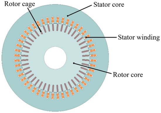
Figure 1.
Cross section of the induction machine.

Table 1.
Main parameters of the IM.
2.2. Design of SynRM
The SynRM and the induction motor are the same in the selection of the motor parameters. The multi-layer magnetic barrier structure is applied in the rotor of the SynRM, so there are many design parameters for the rotor. Figure 2 mainly shows the number of layers of magnetic barriers, the thickness of the d-axis magnetic barriers (W1, W2, W3), the thickness of the q-axis magnetic barriers (W4, W5, W6), the width of the d-axis permeability channels (L1, L2, L3), the width of the q-axis permeability channels (H1, H2, H3) and the width of the rotor magnetic bridge (Rid). In order to obtain a better performance of the SynRM, the influence of various rotor design parameters of the synchronous reluctance motor on motor performance is analyzed. When the number of magnetic barrier layers is greater than or equal to 4, the average torque is almost consistent with the increase in the number of magnetic barrier layers [25]. The more layers in the magnetic barrier, the more difficult it is to manufacture. The SynRM in this paper is designed as a three-layer magnetic barrier structure.
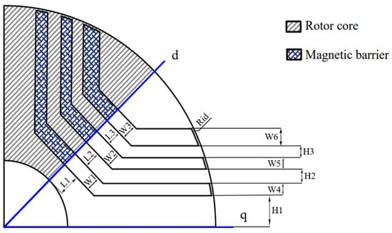
Figure 2.
Cross section of the SynRM with three magnetic barriers and all dimensional variables.
The variation in the d-axis and q-axis inductance and power factor with Rid is shown in Figure 3. Under the premise that the magnetic barrier and other structural parameters remain unchanged, the width of Rid gradually increases from 0.5 mm to 3 mm, the salient pole rate K and ΔL gradually decrease, and the power factor also decreases rapidly. Under the premise of ensuring the mechanical strength of the rotor, a smaller Rid should be selected to obtain better electromagnetic performance.
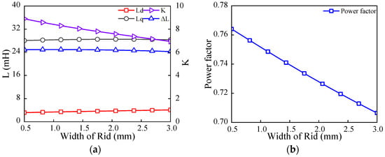
Figure 3.
Influence of Rid on inductance and power factor: (a) d-axis and q-axis inductance; (b) power factor.
Under the premise that the magnetic barriers and other structural parameters remain unchanged, when the width of W4, W5 and W6 gradually increases from 4 mm to 8 mm, the average output torque presents a gradually decreasing trend, as shown in Figure 4a, and the torque ripple presents a downward trend, as shown in Figure 4b. In order to reduce the torque ripple, the width of W4 should be correctly selected. As shown in Figure 4c, the power factor is significantly influenced by the width of W4 and W5.

Figure 4.
Influence of W4, W5 and W6 on (a) load torque, (b) torque ripple and (c) power factor.
The relationship between load torque and torque ripple with H2 and H3 is shown in Figure 5. As the width of H2 and H3 increases, the output torque changes slowly. At the same time, the overall torque ripple shows an upward trend. From the above analysis, the widths of H2 and H3 have less influence on the performance of the SynRM.
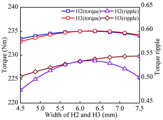
Figure 5.
Load torque and torque ripple versus H2 and H3.
Figure 6 shows the variation in the torque and power factor with the change in the width of the d-axis magnetic barriers. As seen in Figure 6a,b, when the width of W1 increases from 5 mm to 15 mm, the torque ripple gradually decreases. As the width of W2 increases from 5mm to 15mm, the torque ripple gradually increases. When the width of W3 increases from 5 mm to 10 mm, the torque ripple shows an overall increasing trend. In Figure 6c,d, as the width of W1 gradually increases, the torque continues to increase, while the output torque changes slowly with the increase in W2’s width. Additionally, with the increase in W3’s width, the torque increases gradually. In Figure 6e,f, with the width of W1 increasing from 5 mm to 15 mm, the power factor continues to increase. With the width of W2 increasing from 5 mm to 15 mm, the power factor increases slightly. With the width of W3 increasing from 5 mm to 10 mm, the increase in the proportion of the power factor is small. In summary, the width of W1 has a great impact on the performance of the SynRM, so the design of W1 should be emphasized.
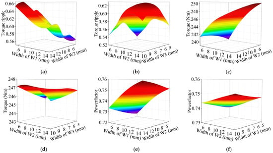
Figure 6.
Responses of (a,b) torque ripple, (c,d) output torque and (e,f) power factor to width of W1, W2 and W3.
Figure 7 shows the variation in the torque and torque ripple with the change in the width of the d-axis magnetic channels. As the widths of L2 and L3 increase, the output torque grows rapidly, while the torque ripple of the motor tends to decrease. In short, the widths of L2 and L3 significantly affect the output torque capability of the SynRM.
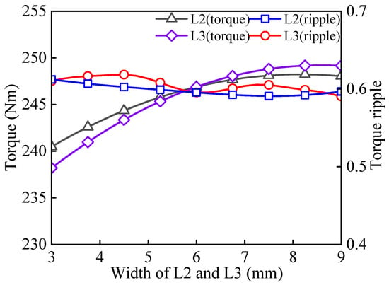
Figure 7.
Load torque and torque ripple versus L2 and L3.
2.3. Design of Ferrite-Assisted SynRM
The influence of the various magnetic barrier design parameters on the performance of the SynRM is analyzed above to determine the parameters of the magnetic barrier. Based on the determination of the SynRM, ferrite is added to the magnetic barrier to form a ferrite-assisted SynRM. The next section focuses on the effect of the length of ferrite (S1, S2, S3) on the performance of the ferrite-assisted SynRM. The structural diagram of the ferrite-assisted SynRM is shown in Figure 8.
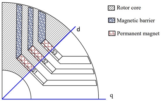
Figure 8.
Cross sections of the ferrite-assisted SynRM with three magnetic barriers and all dimensional variables.
The thickness of the ferrites is the same as that of the magnetic barriers, and the length of each ferrite layer needs to be analyzed. Figure 9 mainly shows the changes in the torque, torque ripple and power factor caused by the change in the length of the ferrites. As shown in Figure 9a, as the length of S1, S2 and S3 increases from 30 mm to 70 mm, the output torque of the motor presents an upward trend, among which the length of S1 has the greatest influence on the output torque. At the same time, the increase in S1’s length makes the torque ripple decrease significantly, while the increase in the length of S2 and S3 makes the torque ripple increase slightly. As shown in Figure 9b, as the length of S1, S2 and S3 increases from 30 mm to 70 mm, the power factor increases gradually. It can be clearly seen that an increase in the length of S1 will increase the power factor more significantly.
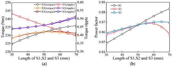
Figure 9.
Influence of S1, S2 and S3 on (a) load torque and (b) power factor.
2.4. Design of IPM
The stator’s structural parameters of the IPM are the same as those of the induction machine. The design parameters are listed in Table 1. The interior V-shape is selected as the rotor structure of the IPM. The interior V-type permanent-magnet motor is widely used for various applications. The rotor design parameters of the IPM mainly include the length (C) and thickness (D) of rare-earth permanent magnets, the angle of the magnetic poles (G) between the permanent magnets, and the width of the magnetic bridge (U) of the rotor. A cross section of the IPM is shown in Figure 10.
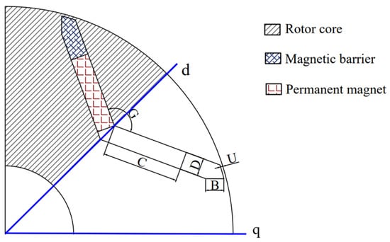
Figure 10.
Cross sections of the IPM with all dimensional variables.
Figure 11 mainly shows that the torque, torque ripple and power factor change with the size of the permanent magnets and the width of the rotor magnetic bridge. As the length of C increases from 30 mm to 70 mm, the output torque increases substantially. When the angle G of the magnetic pole increases from 100 deg to 170 deg, the output torque increases significantly, and then, becomes flat. When the thickness of D increases from 4 mm to 10 mm, the torque increases gradually. When the width of U increases from 0.5 mm to 3 mm, the output torque shows a downward trend. Additionally, when the length of C and the width of U increase gradually, the torque ripple shows a decreasing trend. When the thickness of D increases from 4 mm to 10 mm, the torque ripple also increases. The increase in U’s width makes the torque ripple decrease more obvious. When the angle G increases from 100 degrees to 170 degrees, the overall variation in torque ripple is relatively small. Furthermore, as the length of C increases, the power factor increases first, and then, decreases. As the width of U increases from 0.5 mm to 3 mm and the angle of G increases from 100 deg to 170 deg, the power factor increases slightly. When the thickness of D increases, the motor power factor decreases continuously.
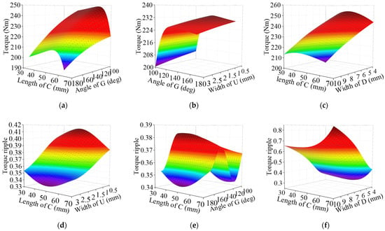

Figure 11.
Responses of (a–c) output torque, (d–f) torque ripple and (g–i) power factor with width of C, G, D and U.
3. Four Kinds of Machine Performance and Comparison
The induction motor used as a reference in this article is a standard induction motor with IE4 energy efficiency. Through the above analysis, the SynRM, ferrite-assisted SynRM and IPM will be optimized. The variation ranges of the optimized design parameters are listed in Table 2.

Table 2.
Optimization parameters and variation range.
The efficiency and torque ripple performance are important for four types of motor.
where is the efficiency, and is the torque ripple.
In this optimization process, the constraints include the output torque, power factor, torque ripple and output power.
where is the output torque, is the power factor of the SynRM and ferrite-assisted SynRM, is the power factor of the IPM, and is the output power.
The response surface expression and genetic algorithm (GA) are obtained using the optimization module of the Ansys Workbench. After optimization, the design parameters of the SynRM, ferrite-assisted SynRM and IPM are determined. To ensure the fairness of the comparison, the only difference between the four motors is the rotor structure. Structural diagrams of the four motors are shown in Figure 12. The rotor design parameters of the SynRM, ferrite-assisted SynRM and IPM are listed in Table 3.
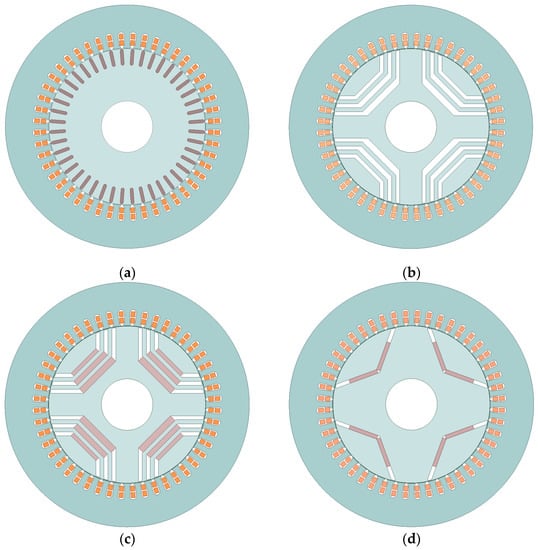
Figure 12.
Cross section of the four machines. (a) Induction machine, (b) SynRM, (c) ferrite-assisted SynRM, (d) IPM.

Table 3.
Optimized design parameters of the SynRM, ferrite-assisted SynRM and IPM.
3.1. Comparison of Electromagnetic Properties
In this paper, finite element analysis (FEA) is used to calculate the core loss and the copper loss. In the calculation process, the mechanical losses of the four types of motor are kept the same. The efficiencies of the four types of motors are shown in Figure 13a. It is seen that the efficiency of the induction machine is 91.76%, while the efficiency of the other three machines ranges from 94% to 95%, about 2.5% higher than that of the induction machine. Due to the special rotor structure of the SynRM, ferrite-assisted SynRM and IPM, the power factor of three machines depends on the contribution of the permanent magnets and the salient pole rate of the rotor structure. The power factor is 0.8 for the SynRM, 0.9 for ferrite-assisted the SynRM and 0.97 for the IPM. The power factor of the ferrite-assisted SynRM is higher than that of the IM, and it is lower than that of the IPM. As shown in Figure 13b, the copper and iron losses of the induction motor are higher than those of several other motors when operating at the rated load. The total losses of the other three motors are equivalent.
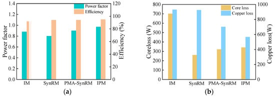
Figure 13.
Electromagnetic performance of the four motors: (a) efficiency and power factor; (b) core loss and copper loss.
The torque curves of the four motors are shown in Figure 14. In the present study, it is known that the torque ripple can be effectively reduced by using the skewed slots and skewed poles [26]. Torque ripple needs to be reduced as much as possible in motor design. Torque ripple refers to the motor running stably, and the output torque of the motor is not a constant value but a positive and negative ripple centered on the average value over time. Numerically, the torque ripple is the ratio of the difference between the maximum and minimum values of the output torque at the rated load to the average output torque. Through the analysis and optimization of the rotor structure parameters, the reasonable parameters are selected and skewed slots are adopted to decrease the torque ripple. It can be seen that the torque ripples of the SynRM and the IPM are close, at about 14.6%. The torque ripple of the ferrite-assisted SynRM is 11.4%. The torque ripple of the IM is the smallest, at about 11.23%.
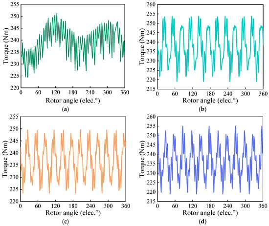
Figure 14.
Torque curves of (a) IM, (b) SynRM, (c) ferrite-assisted SynRM and (d) IPM.
When the four motors operate at the rated speed without any load, the no-load line back-electromotive force (back-EMF) and air gap radial flux density can be obtained, as shown in Figure 15. As seen, the waveform of the ferrite-assisted SynRM is relatively sinusoidal, while the no-load line back-EMF of the IPM has more harmonics. The RMS value of the no-load line back-EMF of the ferrite-assisted SynRM is about 87 V, while that of the IPM is about 338 V. Additionally, due to the different magnetic properties of the ferrites and rare-earth PMs, the radial air-gap magnetic flux density amplitude of the IPM is larger. The radial air-gap flux density of the ferrite-assisted SynRM is smaller, and the flux density is more uniformly distributed. The performances of the four motors are summarized in Table 4.
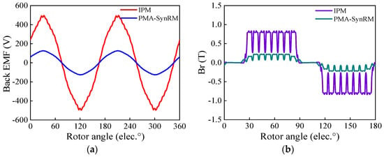
Figure 15.
(a) Back-EMF versus rotor position. (b) Air gap radial flux density versus rotor position.

Table 4.
Comparison of the electromagnetic performance of the four types of machines.
It is well known that ferrite-assisted synchronous reluctance motors have the risk of irreversible demagnetization. Since the magnetic properties of ferrites are much weaker than those of rare-earth permanent magnets, irreversible demagnetization can occur very easily under overload conditions. In this paper, the ferrite of Y30 is used in the ferrite-assisted synchronous reluctance motor. The inflection point of the demagnetization curve of the Y30 is about 0.18T. Figure 16 shows the demagnetization of the Y30 under different load conditions. No irreversible demagnetization occurs in the three-layer Y30 under the rated load. Under 1.5 times the load, irreversible demagnetization occurs locally in the second and third layers of the ferrites. Under two times the rated load, the three layers of ferrite undergo different degrees of irreversible demagnetization, with the third layer suffering the most serious irreversible demagnetization. This paper mainly considers the condition of the four motors running under the rated load, so the design of the ferrite-assisted synchronous reluctance motor is reasonable.

Figure 16.
Demagnetization of the ferrites: (a) rated load; (b) under 1.5 times the load; (c) under 2 times the load.
In Figure 17, the mechanical characteristics and torque output capability of the four motors are described. It can be seen from the diagram that the torque–speed characteristics and torque output capacity of the SynRM are weaker than those of the other three motors. The torque–speed characteristics of the IM and the IPM are similar. In the low-load region, the torque–speed characteristics and torque output capacity of the IPM and the IM are better than those of the ferrite-assisted SynRM. In the high-load area, the torque–speed characteristics and torque output capacity of the IPM are weaker than those of the ferrite-assisted SynRM. When the load is high, the influence of the permanent magnets on the IPM is small, while the salient pole ratio of the ferrite-assisted SynRM is high.

Figure 17.
The characteristics of the four motors. (a) Torque–speed, rated current. (b) Power–speed, rated current. (c) Maximum torque–current.
3.2. Motor Temperature Comparison
Through the above analysis, the losses of the four machines under rated load are analyzed. Motor-CAD software is used to obtain the temperature distribution of the motors by adopting the cooling scheme of the flow of fluid through the machine, as shown in Figure 18. Under the above cooling system, the temperature distribution of the IM is shown in Figure 18a. As seen, the maximum temperature in the IM motor is 126.1 °C of the rotor cage. The maximum temperature of the SynRM is 113.0 °C of the winding, as shown in Figure 18b. The maximum temperature of the ferrite-assisted SynRM is 105.9 °C upon winding, as shown in Figure 18c. The maximum temperature of the IPM is 103.2 °C upon winding, as shown in Figure 18d. For the stator core, the temperatures of the SynRM, the IPM and the ferrite-assisted SynRM are similar, at about 10 °C lower than that of the IM. The temperatures of the rotor core of the SynRM, IPM and ferrite-assisted SynRM are equivalent, at about 40 °C lower than that of the IM. The maximum temperature of the permanent magnets of the ferrite-assisted SynRM is 82.3 °C, which is 1.4 °C higher than that of the IPM. In summary, the IM has the largest iron loss and copper loss, so its temperature is generally higher than that of the other three motors. The temperatures of the ferrite-assisted SynRM and the IPM are generally close to each other, and the maximum temperature difference between the two motors is only 2.7 °C. A temperature comparison of the four machines at the main positions is shown in Figure 19.
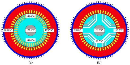
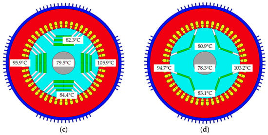
Figure 18.
Temperature distribution of the electrical machines. (a) Induction machine, (b) SynRM, (c) ferrite-assisted SynRM and (d) IPM.
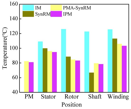
Figure 19.
Temperature comparison of the main positions of the four machines.
3.3. Machine Material Cost Comparison
Through an analysis of the current market, quotations for various materials were obtained.
- Cost of iron lamination: 2.12 USD/kg;
- Cost of copper: 14.85 USD/kg;
- Cost of ferrite PM: 0.17 USD/kg;
- Cost of NdFeB PM: 84.87 USD/kg;
- Cost of aluminum: 4.25 USD/kg.
The material costs and weights of the four motors are listed in Table 5. Under the premise that the four kinds of machine meet the required performance indexes, the weight of the electromagnetic materials of the SynRM is the smallest, and that of the IM is the largest. The weight of the IPM is 30.53 kg heavier than that of the ferrite-assisted SynRM. From the perspective of motor production cost, the IPM has the highest cost. The costs of the SynRM and the ferrite-assisted SynRM are very close, at about 33% lower than the cost of the IPM and 23% lower than the IM.

Table 5.
Material costs of the SynRM, ferrite-assisted SynRM, IPM and induction machine.
4. Conclusions
In this paper, the induction motor, synchronous reluctance motor, permanent-magnet-assisted synchronous reluctance motor and interior permanent-magnet motor are comprehensively compared. Firstly, the volume and stator structure of the four motors are guaranteed to be the same. Then, the influence of the rotor parameters on electromagnetic performance is analyzed, and the motors are optimized using a genetic algorithm (GA). Finally, the electromagnetic performance, material cost and temperature of the four motors are compared. The comparison results are as follows:
- In terms of the electromagnetic performance, the efficiencies of the IPM, SynRM and ferrite-assisted SynRM are equivalent, at about 2.5% higher than that of the IM. The power factor of the SynRM is lower than that of the other three motors. The power factor of the ferrite-assisted SynRM is higher than that of the IM, and lower than that of the IPM. The torque ripples of the SynRM and the IPM are close, at about 14.6%. The torque ripple of the ferrite-assisted SynRM is 11.4%. The torque ripple of the IM is the smallest, at about 11.23%.
- For the motor temperature: the stator copper loss and core loss of the IM are much higher than those of the other three motors. Regarding the comparison of the SynRM, ferrite-assisted SynRM and IPM, the iron loss of the SynRM is the highest, and the copper loss of the IPM is the highest, but the total losses of the three motors are equivalent. Under the same cooling method, the temperature of the IM can be up to 126.1 °C. The temperatures of the ferrite-assisted SynRM and the IPM are equivalent, at about 20 °C lower than that of the IM.
- In terms of the motor material cost and weight: the weight of the SynRM and the ferrite-assisted SynRM is about 50% lower than that of the IM. The weight of the IPM is about 30 kg heavier than that of the SynRM and the ferrite-assisted SynRM. The costs of the SynRM and the ferrite-assisted SynRM are very close, at about 33% lower than the cost of the IPM and 23% lower than the IM.
- The manufacturing process and control system of the IM are very mature, but its electromagnetic performance needs to be further improved. The power factor, efficiency and torque density of the IPM are excellent, but the cost of the motor needs to be considered. The structure of the SynRM is simple and the cost is very low, but its low torque density and low power factor limit its development. The electromagnetic performance of some of the ferrite-assisted SynRMs are better than that of the IM and the SynRM, and its cost is much lower than that of the IPM. However, it is necessary to pay attention to the torque ripple of the ferrite-assisted synchronous reluctance motor and the demagnetization of the ferrites.
It is very important to select the appropriate motor type for different applications. This paper comprehensively compares the four common motors, and provides a certain reference significance for the selection and application of motors.
Author Contributions
Conceptualization, G.D.; Data curation, G.D. and G.Z.; Formal analysis, G.Z.; Funding acquisition, G.D.; Investigation, G.D. and G.Z.; Methodology, G.D. and G.Z.; Project administration, G.D.; Resources, G.D.; Software, G.Z.; Supervision, H.L.; Validation, G.D., H.L. and C.H.; Visualization, G.Z.; Writing—original draft, G.Z.; Writing—review and editing, G.D., G.Z., H.L. and C.H. All authors have read and agreed to the published version of the manuscript.
Funding
This research received no external funding.
Institutional Review Board Statement
Not applicable.
Informed Consent Statement
Not applicable.
Data Availability Statement
Not applicable.
Conflicts of Interest
The authors declare no conflict of interest.
References
- Bao, Y.L.; Degano, M.; Wang, S.; Liu, C.; Zhang, H.; Xu, Z.; Gerada, C. A Novel Concept of Ribless Synchronous Reluctance Motor for Enhanced Torque Capability. IEEE Trans. Ind. Electron. 2020, 67, 2553–2563. [Google Scholar] [CrossRef]
- Dmitrievskii, V.; Prakht, V.; Kazakbaev, V. IE5 Energy-Efficiency Class Synchronous Reluctance Motor with Fractional Slot Winding. IEEE Trans. Ind. Appl. 2019, 55, 4676–4684. [Google Scholar] [CrossRef]
- Chen, Q.; Yan, Y.J.; Xu, G.; Xu, M.M.; Liu, G.H. Principle of Torque Ripple Reduction in Synchronous Reluctance Motors with Shifted Asymmetrical Poles. IEEE J. Emerg. Sel. Top. Power Electron. 2020, 8, 2611–2622. [Google Scholar] [CrossRef]
- Diao, K.K.; Sun, X.D.; Lei, G.; Guo, Y.G.; Zhu, J.G. Multiobjective System Level Optimization Method for Switched Reluctance Motor Drive Systems Using Finite-Element Model. IEEE Trans. Ind. Electron. 2020, 67, 10055–10064. [Google Scholar] [CrossRef]
- Zhang, Y.; Yu, S.Y.; Liu, G.W.; Zhang, H. Comparative Research for a Novel Dual-Stator Synchronous Machine with Permanent Magnet-Reluctance Composite Rotor. IEEE Trans. Appl. Supercond. 2020, 30, 1–5. [Google Scholar] [CrossRef]
- Islam, Z.; Bonthu, S.S.R.; Choi, S. Design of a Robust Five-Phase Ferrite-Assisted Synchronous Reluctance Motor with Low Demagnetization and Mechanical Deformation. IEEE Trans. Energy Convers. 2019, 34, 722–730. [Google Scholar] [CrossRef]
- Boglietti, A.; Pastorelli, M. Induction and Synchronous Reluctance Motors Comparison. In Proceedings of the 2008 34th Annual Conference of IEEE Industrial Electronics, Orlando, FL, USA, 10–13 November 2008; pp. 2041–2044. [Google Scholar]
- Liu, G.H.; Wang, Y.; Chen, Q.; Xu, G.H.; Cao, D.H. Design and Analysis of a New Equivalent Magnetic Network Model for IPM Machines. IEEE Trans. Magn. 2020, 56, 8101112. [Google Scholar] [CrossRef]
- Morimoto, S.; Ooi, S.; Inoue, Y.; Sanada, M. Experimental Evaluation of a Rare-Earth-Free PMASynRM with Ferrite Magnets for Automotive Applications. IEEE Trans. Ind. Electron. 2014, 61, 5749–5756. [Google Scholar] [CrossRef]
- Obata, M.; Morimoto, S.; Sanada, M.; Inoue, Y. Performance of PMASynRM with Ferrite Magnets for EV/HEV Applications Considering Productivity. IEEE Trans. Ind. Appl. 2014, 50, 2427–2435. [Google Scholar] [CrossRef]
- Cai, H.W.; Guan, B.; Xu, L.Y. Low-Cost Ferrite PM-Assisted Synchronous Reluctance Machine for Electric Vehicles. IEEE Trans. Ind. Electron. 2014, 61, 5741–5748. [Google Scholar] [CrossRef]
- Xu, M.M.; Liu, G.H.; Chen, Q. Torque Ripple Improvement for Ferrite-Assisted Synchronous Reluctance Motor by Using Asymmetric Flux-Barrier Arrangement. Int. J. Appl. Electromagn. Mech. 2019, 60, 479–488. [Google Scholar] [CrossRef]
- Xu, M.M.; Liu, G.H.; Zhao, W.X.; Aamir, N. Minimization of Torque Ripple in Ferrite-Assisted Synchronous Reluctance Motors by Using Asymmetric Stator. AIP Adv. 2018, 8, 056606. [Google Scholar] [CrossRef]
- Paradkar, M.; Boecker, J. Design of a High Performance Ferrite Magnet-Assisted Synchronous Reluctance Motor for an Electric Vehicle. In Proceedings of the IECON 2012—38th Annual Conference on IEEE Industrial Electronics Society, Montreal, QC, Canada, 25–28 October 2012; pp. 4099–4103. [Google Scholar]
- Pellegrino, G.; Cupertino, F.; Gerada, C. Automatic Design of Synchronous Reluctance Motors Focusing on Barrier Shape Optimization. IEEE Trans. Ind. Appl. 2015, 51, 1465–1474. [Google Scholar] [CrossRef]
- Williamson, S.; McClay, C.I. Optimization of the Geometry of Closed Otor Slots for Cage Induction Motors. IEEE Trans. Ind. Appl. 1996, 32, 560–568. [Google Scholar] [CrossRef]
- Gerada, D.; Mebarki, A.; Brown, N.L.; Gerada, C.; Cavagnino, A.; Boglietti, A. High-Speed Electrical Machines: Technologies, Trends, and Developments. IEEE Trans. Ind. Electron. 2014, 61, 2946–2959. [Google Scholar] [CrossRef]
- Yang, Y.; Castano, S.M.; Yang, R.; Kasprzak, M.; Bilgin, B.; Sathyan, A.; Dadkhah, H.; Emadi, A. Design and Comparison of Interior Permanent Magnet Motor Topologies for Traction Applications. IEEE Trans. Transp. Electrif. 2017, 3, 86–97. [Google Scholar] [CrossRef]
- Zheng, J.; Zhao, W.; Lee, C.H.T.; Ji, J.; Xu, G. Improvement Torque Performances of Interior Permanent-Magnet Machines. Trans. Electr. Mach. Syst. 2019, 3, 12–18. [Google Scholar] [CrossRef]
- Yamazaki, K.; Kumagai, M. Torque Analysis of Interior Permanent-Magnet Synchronous Motors by Considering Cross-Magnetization: Variation in Torque Components with Permanent-Magnet Configurations. IEEE Trans. Ind. Electron. 2014, 61, 3192–3201. [Google Scholar] [CrossRef]
- Bianchi, N.; Alberti, L.; Bottesi, O. Energy Efficiency Improvement Adopting Synchronous Motors. COMPEL Int. J. Comput. Math. Electr. Electron. Eng. 2015, 34, 76–91. [Google Scholar] [CrossRef]
- Boglietti, A.; Cavagnino, A.; Pastorelli, M.; Vagati, A. Experimental Comparison of Induction and Synchronous Reluctance Motors Performance. In Proceedings of the Fourtieth IAS Annual Meeting. Conference Record of the 2005 Industry Applications Conference, Hong Kong, China, 2–6 October 2005; Volume 1, pp. 474–479. [Google Scholar]
- Guan, Y.; Zhu, Z.Q.; Afinowi, I.A.A.; Mipo, J.C.; Farah, P. Design of Synchronous Reluctance and Permanent Magnet Synchronous Reluctance Machines for Electric Vehicle Application. In Proceedings of the 2014 17th International Conference on Electrical Machines and Systems (ICEMS), Hangzhou, China, 22–25 October 2014. [Google Scholar]
- Cai, S.; Jin, M.J.; Hao, H.; Shen, J.X. Comparative Study on Synchronous Reluctance and PM Machines. COMPEL Int. J. Comput. Math. Electr. Electron. Eng. 2016, 35, 607–623. [Google Scholar] [CrossRef]
- Wang, Y.W.; Bacco, G.; Bianchi, N. Geometry Analysis and Optimization of PM-Assisted Reluctance Motors. IEEE Trans. Ind. Appl. 2017, 53, 4338–4347. [Google Scholar] [CrossRef]
- Islam, R.; Husain, I.; Fardoun, A.; McLaughlin, K. Permanent Magnet Synchronous Motor Magnet Designs with Skewing for Torque Ripple and Cogging Torque Reduction. In Proceedings of the 2007 IEEE Industry Applications Annual Meeting, New Orleans, LA, USA, 23–27 September 2007. [Google Scholar]
Disclaimer/Publisher’s Note: The statements, opinions and data contained in all publications are solely those of the individual author(s) and contributor(s) and not of MDPI and/or the editor(s). MDPI and/or the editor(s) disclaim responsibility for any injury to people or property resulting from any ideas, methods, instructions or products referred to in the content. |
© 2023 by the authors. Licensee MDPI, Basel, Switzerland. This article is an open access article distributed under the terms and conditions of the Creative Commons Attribution (CC BY) license (https://creativecommons.org/licenses/by/4.0/).