
Spiking Neural P Systems for Basic Arithmetic Operations


Abstract
1. Introduction
2. Related Research
2.1. Spiking Neural P Systems
- (1)
- O = {a} is a singleton alphabet, where a is called a spike;σ1, σ2, …, σm are neurons of the form σi = (ni, Ri) in the Π system, with 1 ≤ i ≤ m.Where ni ≥ 0 is the number of spikes in neuron σi in the initial configuration, Ri is a finite set of rules of the following two forms:
- (i)
- spiking rule: E/ac→ap; d, where E is a regular expression over O, and c ≥ 1, d ≥ 0, p ≥ 1, c ≥ p;
- (ii)
- forgetting rule: E′/as→λ, where E′ is a regular expression over O, s ≥ 1, furthermore, for each rule E/ac→ap; d in the rule set Ri of type (i), it holds that, where L(E) is the language generated by E.
- (2)
- is a finite set of synapses between neurons. (σi, σj) ∈ syn means that there is a synaptic connection from σi to neuron σj. For any i, 1 ≤ i ≤ m, (σi, σi)syn;
- (3)
- indicate the input and output neurons, respectively. In particular, we use σ0 to denote the environment of the system.
2.2. Research on Arithmetic Operation of SNP
3. Arithmetic Operation in Spiking Neural P Systems
- (1)
- A unified clock is used to manage and maintain the operation process, with the unit of time being the time slice. The execution of each rule in the SNPS only requires one time slice.
- (2)
- The binary strings involved in the operations have k digits. If a string has less than k digits, it is padded with leading zeros to reach k digits.
- (3)
- The SNPS can accept one binary digit per time slice. When a binary digit of 1 is received, this means the system has received a spike; otherwise, no spike is received. The system receives the input binary string from the least significant bit to the most significant bit.
- (4)
- In the addition, subtraction, and multiplication SNPS the system operation result is outputted by the output neurons from low to high bits in the form of a binary string. In the division SNPS the operation result is stored in a set of result neurons.
- (5)
- In our designed SNPS we set parameter d in the rule description of Formula (1) to 0. This means that both the spiking rule and the forgetting rule will be executed immediately once the conditions are satisfied.
3.1. Binary Addition in SNP Systems
- (1)
- By inputting the binary string of the addend from the lowest bit to the highest bit using the input neuron σinput, if the i-th bit (0 ≤ i ≤ k − 1) in the input string is 1, the neuron σinput generates one spike; otherwise, it generates no spike.
- (2)
- After each bit of the augend is input, it is buffered in the system and waits for the input of the addend. When the highest bit of the augend is input, the addend is immediately input.
- (3)
- When the i-th bit (0 ≤ i ≤ k − 1) of the augend reaches the addition neuron σAdd, the i-th bit of the addend is taken out from the buffer and input to σAdd. The addition operation is performed by the rules in σAdd.
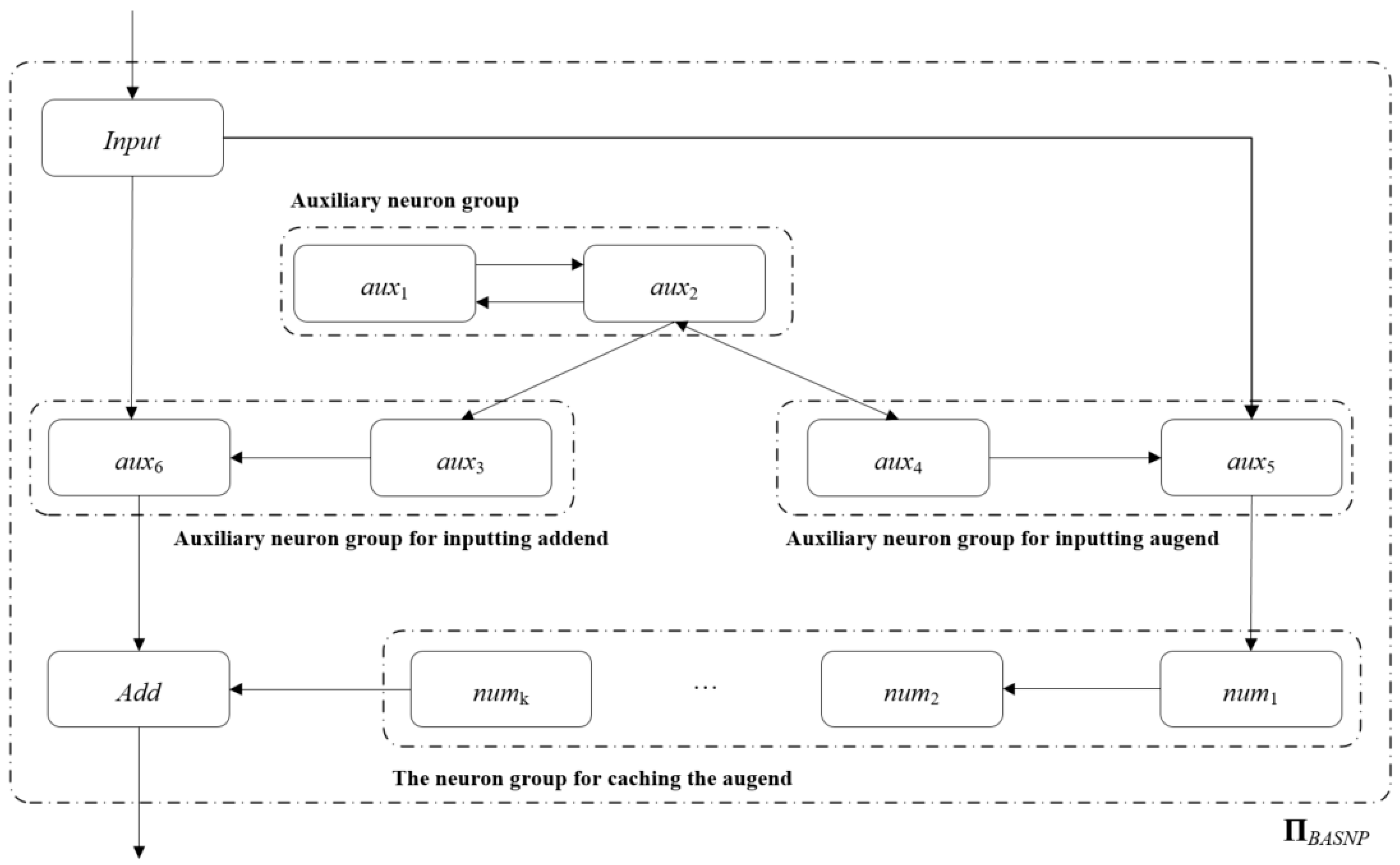
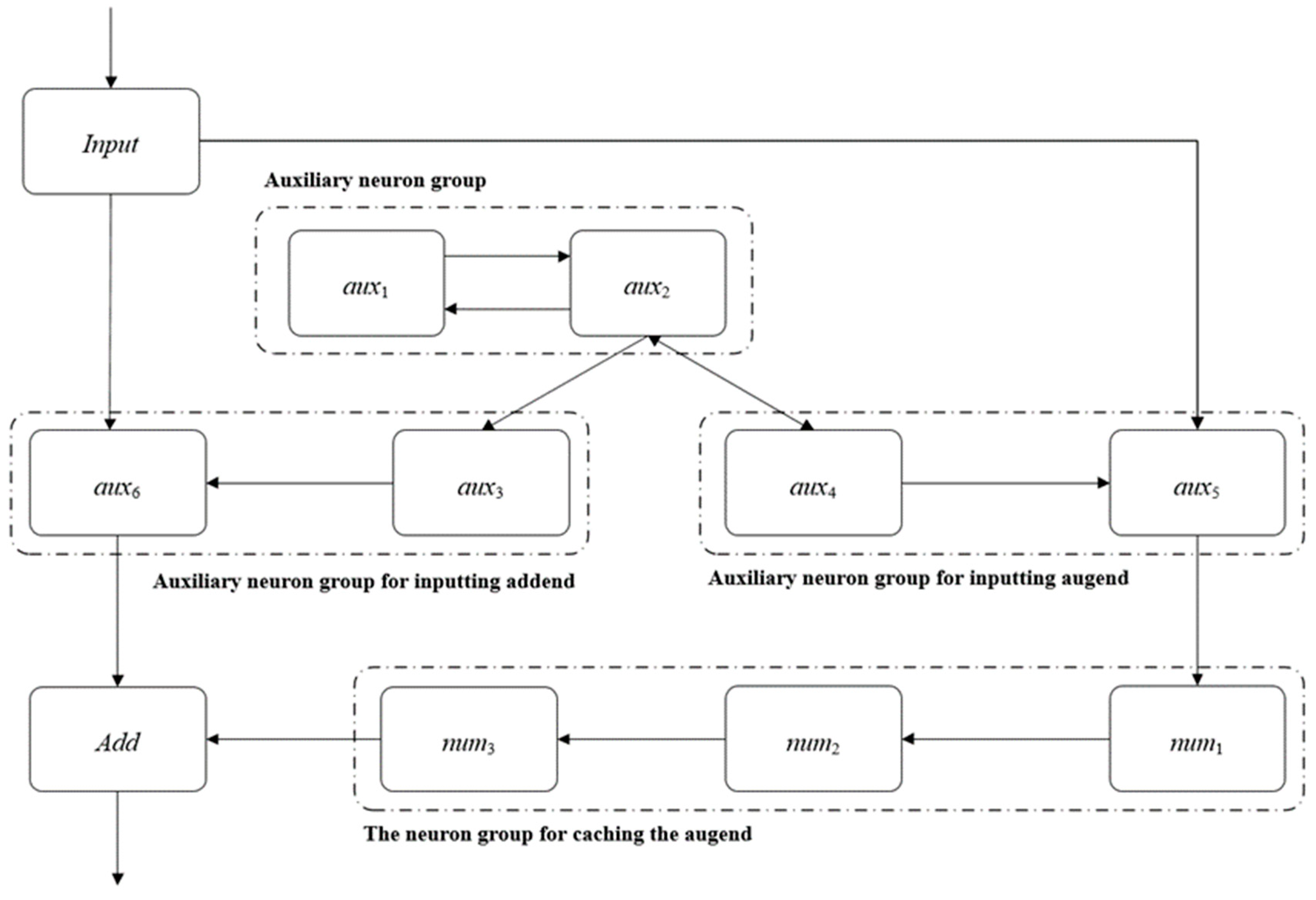
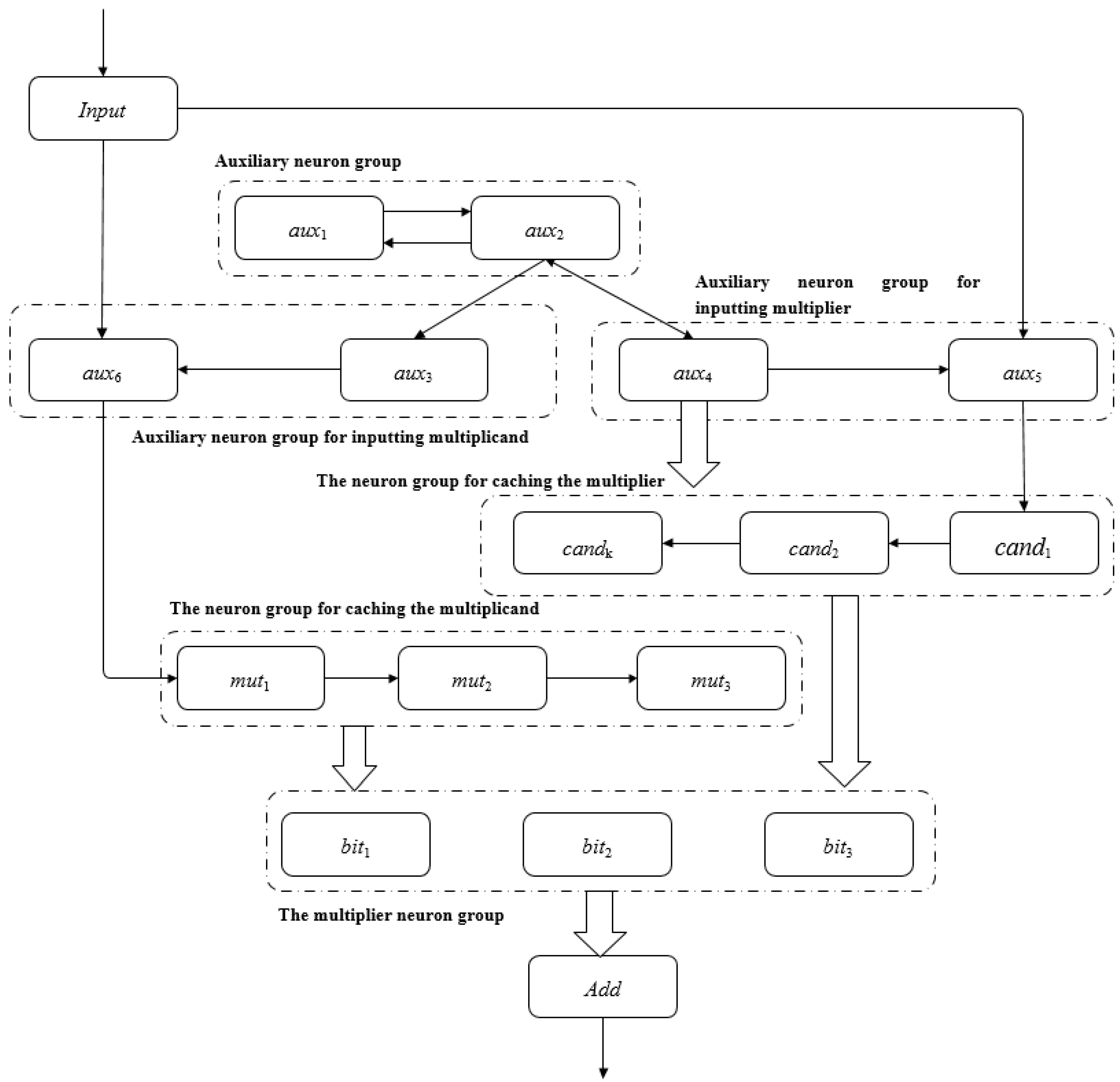
- Neuron-to-neuron connections are indicated by thin arrows, for example, the connection between σaux1 and σaux2 in Figure 1.
- Connections of neurons to groups of neurons are indicated by thick arrows. Specifically, if the front end of the thick arrow is a single neuron σ0, and the end is a neuron group σx = {σ1, σ2, …, σn}, this means that each neuron σi (1 ≤ i ≤ n) in neuron σ0 is connected to neuron group σx; on the contrary, if the front end of the thick arrow is a neuron group σx, and the end is a single neuron σ0, this means that each neuron in the neuron group σx has a connection to neuron σ0.
- Group-to-neuron connections are indicated by thick arrows. If the front end of the thick arrow is a neuron group σx = {σ1, σ2, …, σn} and the end is a neuron group σx′ = {σ1′, σ2′, …, σn′}, then two neurons in the same order from the group σx to the neuron group σx′ are connected, that is, there is a connection from σi to σi′, 1 ≤ i ≤ n.
- (1)
- O = {a};
- (2)
- σInput = (0,RInput), RInput = {a→a};
- (3)
- σaux1 = (1,Raux1), Raux1 = {a→a};
- (4)
- σaux2 = (1,Raux2), Raux2 = {a→a};
- (5)
- σaux3 = (0,Raux3), Raux3 = {ak→a2};
- (6)
- σaux4 = (0,Raux4), Raux4 = {ak→a2};
- (7)
- σaux5 = (0,Raux5), Raux5 = {a→a; a3/a→λ};
- (8)
- σaux6 = (0,Raux6), Raux6 = {a→λ; a3/a→a};
- (9)
- σnumi = (0,Rnumi), Rnumi= {a→a},;
- (10)
- σAdd = (0,RAdd), RAdd = {a→a; a2/a→λ; a3/a2→a};
- (11)
- syn = {(Input,auxi)|}∪{(aux1,aux2)}∪{(aux2,auxi)|}∪{(aux3,aux6)}∪{(aux4,auxi)|}∪{(aux5,num1)}∪{(numi,numi+1)|}}∪{(numk,Add)};
- (12)
- in = σinput;
- (13)
- out = σ0 (indicates that the system outputs the calculation results to the environment)
- Neuron Input. The Input neuron receives binary strings from the environment and converts them to spikes in ΠBASNP.
- Neuron Add. The bit-by-bit addition of binary strings is realized by spiking rules and forgetting rules.
- Auxiliary neuron groups (aux1, aux2). Continuously send one spike to neurons aux3 and aux4 at each time slice.
- The augend is input to the auxiliary neuron group. Accurately input the spike train representing the augend into the augend cache neuron group, and shield the interference when the augend spike train is input.
- Addend input to auxiliary neuron group. Shield the input of the addend spike train, and accurately input the spike train representing the addend to the neuron Add.
- The augend cache neuron group. Buffer the augend spike train, and send the augend spike train to the neuron Add for operation in due course.
- (1)
- t = 0, start sending the corresponding spike sp-x0 of the lowest bit x0 of X to σInput.
- (2)
- From t = 1 to t = k, the regular execution of ΠBASNP and the change of spikes in each neuron include:
- (i)
- σInput accepts sp-xi (0 ≤ i ≤ k − 1) and applies the corresponding rules to send sp-xi to σaux5. During this period, σaux5 can only receive the spikes sent by σInput, and apply the rules to send the received spikes to σnum1 in turn. Similarly, σnumj (1 ≤ j ≤ k − 2) sends the received spikes to σnumj+1 in sequence.
- (ii)
- σaux6 accepts the spikes sent by σInput, if sp-xi (0 ≤ i ≤ k − 2) = {a}, use the rule a→λ to forget this spike.
- (iii)
- σaux1 and σaux2 (starting to work at t = 1) each maintain one spike, and σaux3 and σaux4 each maintain k − 1 spikes at t = k.
- (iv)
- There is no spike in σAdd.
- (3)
- At time t = k + 1, the rule execution of ΠBASNP and the change of spikes in each neuron include:
- (i)
- σaux6 accepts sp-xk−1 and forgets sp-xk−2.
- (ii)
- σaux1 and σaux2 keep one spike each, σaux3 and σaux4 keep k spikes and apply the rule ak→a2 to send two spikes to σaux5 and σaux6 respectively.
- (iii)
- There is no spike in σAdd.
- (4)
- At time t = k + 2, the rule execution of ΠBASNP and the change of spikes in each neuron include:
- (i)
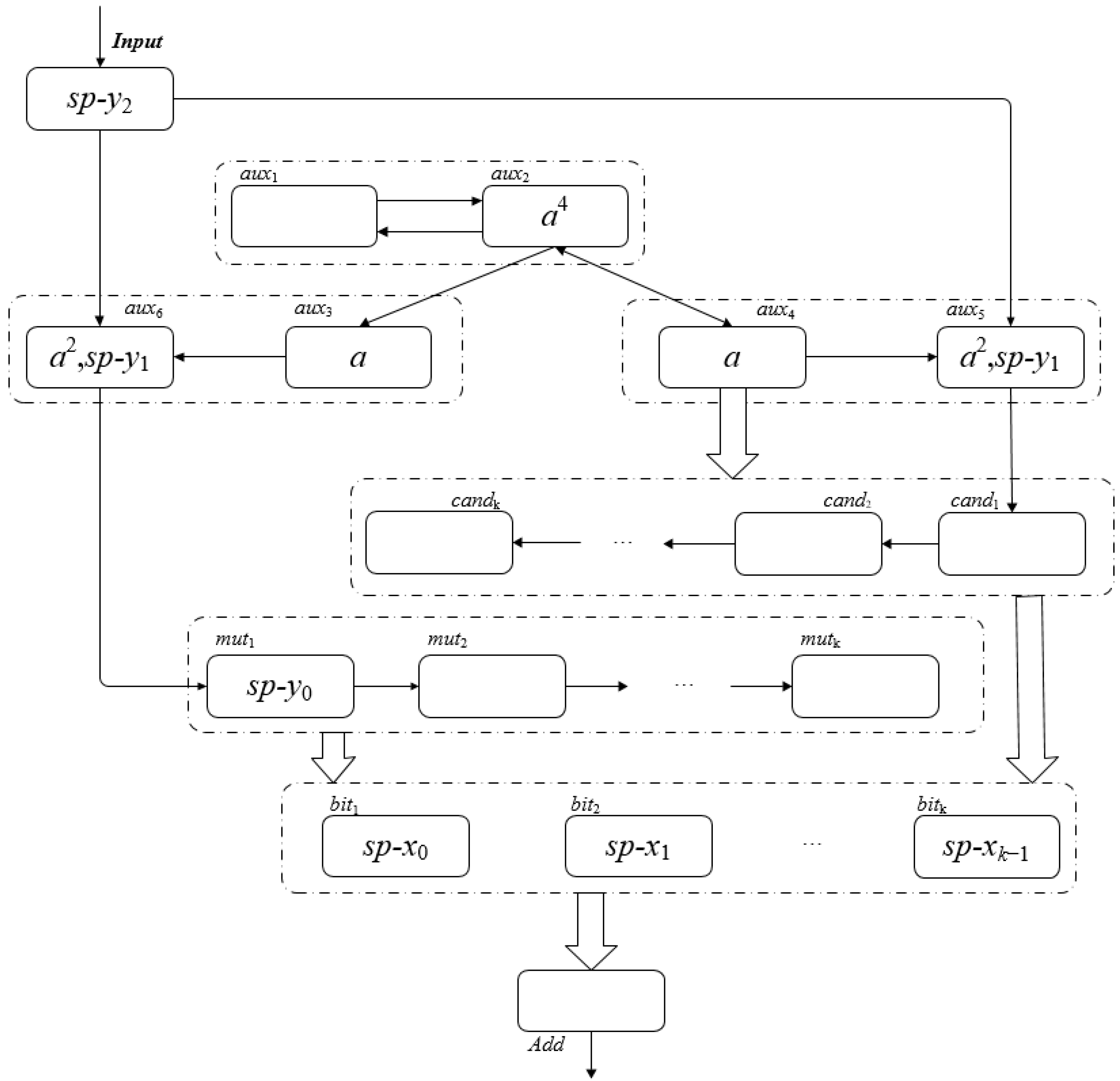
- σInput accepts sp-y1 and sends sp-y0 to σaux5. σaux5 sends sp-xk−1 to σnum1 while receiving sp-y0 and {a2} from σaux4. σnumj (1 ≤ j ≤ k − 1) accepts sp-xk-j and sends sp-xk-j−1, and σnumk accepts sp-x0.
- (ii)
- σaux6 forgets sp-xk−1 accepts both sp-y0 (from σInput) and {a2} (from σaux3).
- (iii)
- σaux1 holds one spike, σaux2 gets three spikes (one spike from σaux1 and two spikes from σaux4), σaux3 and σaux4 hold one spike.
- (iv)
- There is no spike in σAdd.
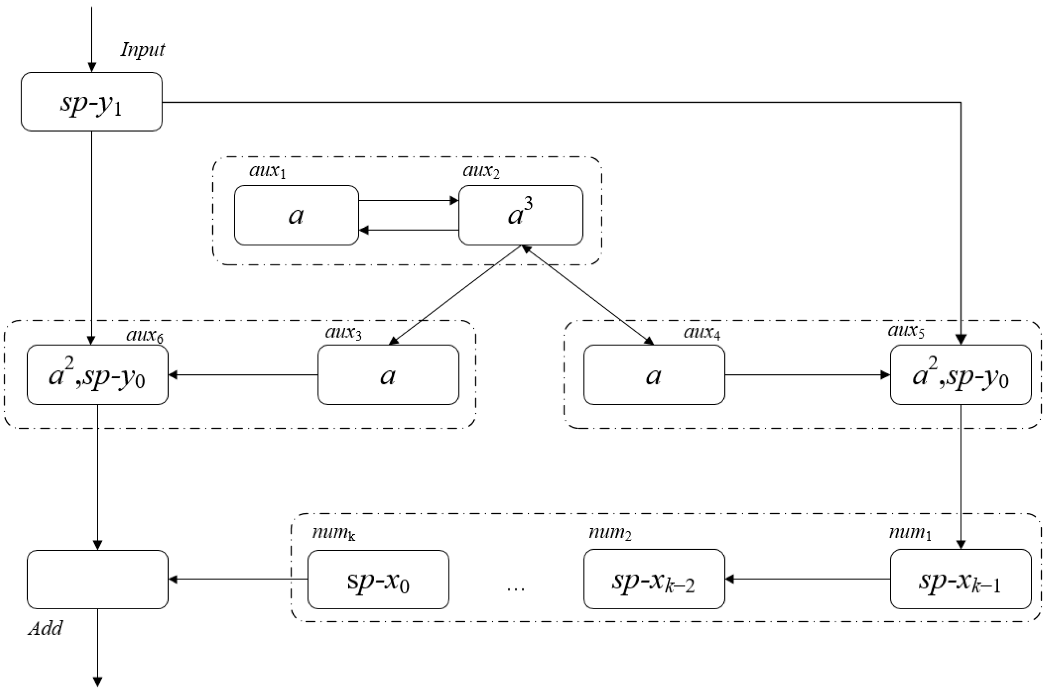
At this point, the augend has been input into the augend cache neuron group and we can obtain Figure 2, which shows the spikes contained in each neuron in the configuration Ck+2. - (5)
- From t = k + 3 to t = 2k + 2, the rule execution of ΠBASNP and the change of spikes in each neuron include:
- (i)
- σInput sequentially accepts sp-yj (2 ≤ j ≤ k − 1) and simultaneously applies the rules to send sp−yj−1 to σaux5 and σaux6. When the number of spikes in σaux5 is three, the rule a3/a→λ is activated and consumes one spike, so there will always be two spikes in σaux5 and no spikes will be sent.
- (ii)
- Since σaux6 keeps two spikes, when it receives a spike from σInput, it will apply the rule a3/a→a to consume one spike and send one spike to σAdd, and make σaux6 keep two spikes.
- (iii)
- σaux1 sends 1 spike to σaux2, σaux2 receives one spike, σaux3 and σaux4 keep one spike.
- (iv)
- Starting from time t = k + 3, σAdd receives sp-xi and sp-yi (0 ≤ i ≤ k − 1) at the same time. Readers can refer to [29] for details of the addition operation in σAdd.
- (v)
- From time t = k + 4, the environment starts to receive calculation results in sequence.
- (vi)
- From t = 2k + 1 time slice, σInput no longer accepts the input of the environment, and only sends the spikes it contains to σaux5 and σaux6 by using the rules.
- (vii)
- At t = 2k + 2, the highest bit xk−1 of X and yk−1 of Y reach the neuron σAdd, if X + Y < 2k+1, the system will reach the termination pattern at t = 2k + 3; If X + Y ≥ 2k+1, the system will eventually reach the termination pattern at t = 2k + 4.
Based on the above description, readers can verify that for k ≥ 2, the SNPS ΠBASNP for addition constructed above can correctly solve the sum of two natural numbers with a binary length of k, and the proof is complete. □
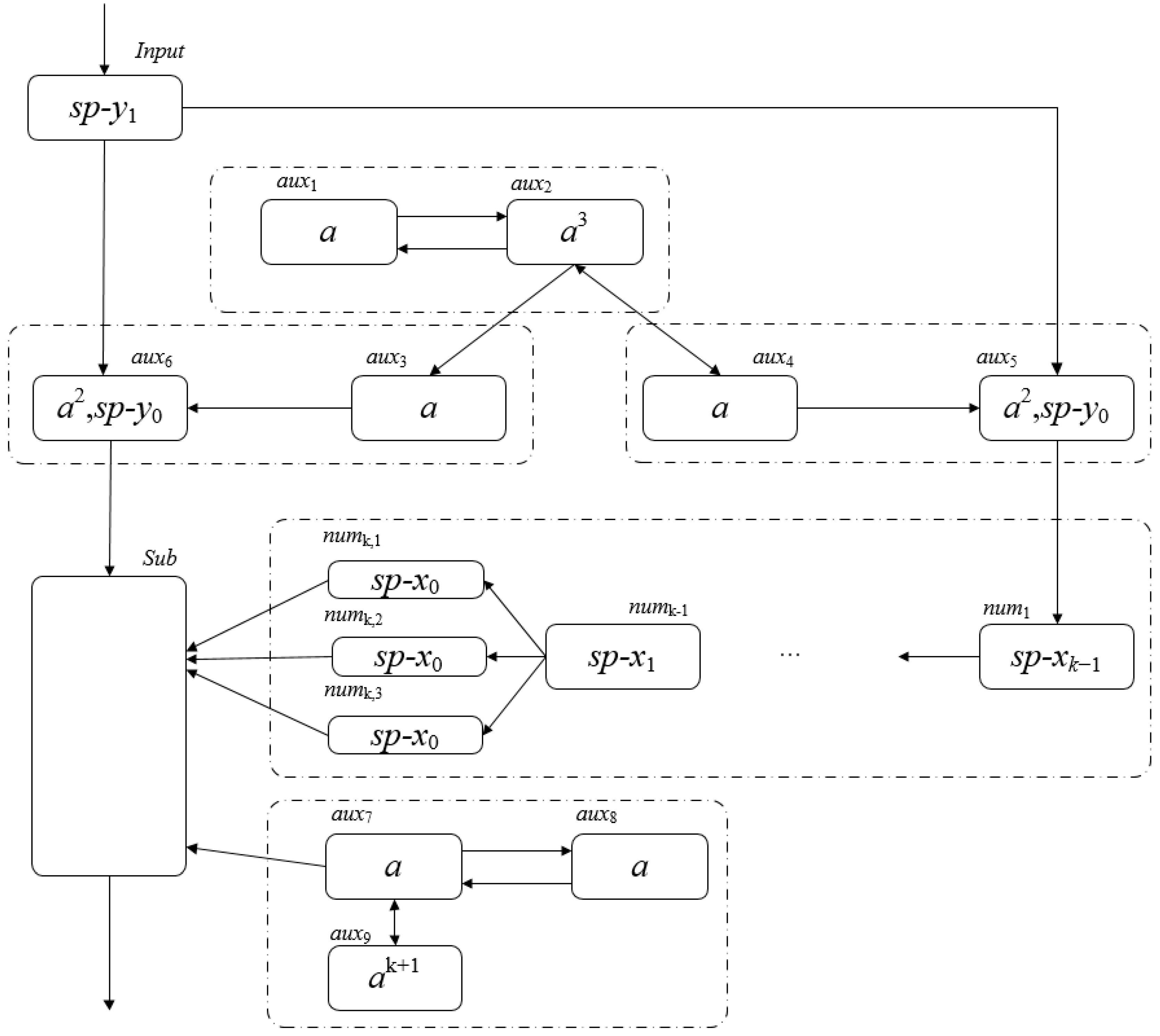
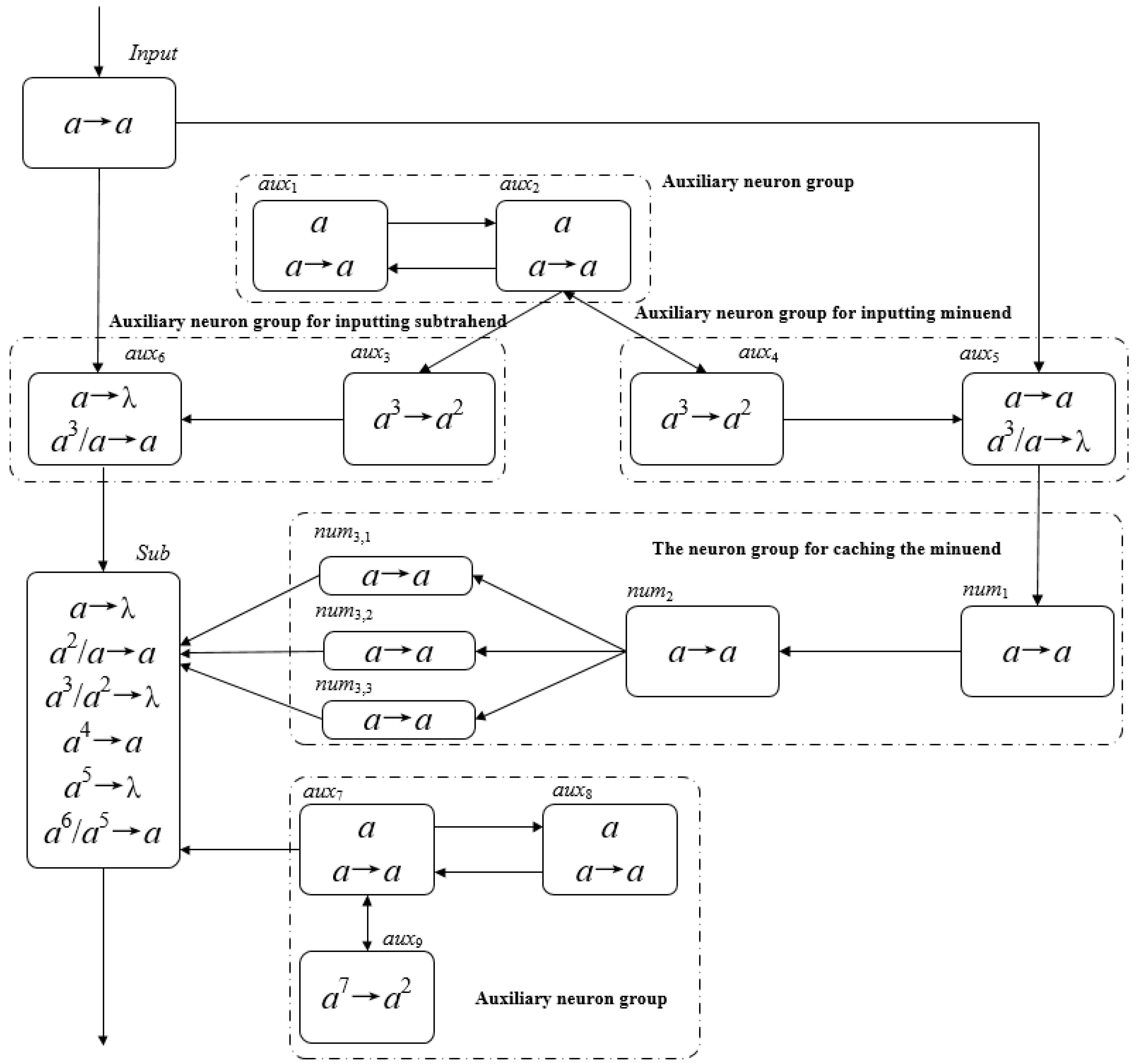
3.2. Binary Subtraction in SNP Systems
- (1)
- Through the input neuron Input, input the binary string of the minuend from the lowest bit to the highest bit. When the i-th bit (0 ≤ i ≤ k − 1) in the input string is 1, the neuron Input gets one spike, otherwise it does not get a spike.
- (2)
- After each digit of the subtrahend is input, it will be cached in the system, waiting for the input of the subtrahend. Input the subtrahend immediately after the highest bit of the minuend is input.
- (3)
- When the i-th bit of the subtrahend (0 ≤ i ≤ k − 1) reaches the subtraction neuron Sub, the i-th bit of the minuend in the cache is taken out and put into the Sub, and the subtraction operation is performed according to the rules in the Sub.
- (4)
- Before the i-th bit of the minuend (0 ≤ i ≤ k − 1) reaches the subtraction neuron Sub, 3 spikes represent the number 1, and 0 spikes represent the number 0.
- (1)
- O = {a};
- (2)
- σInput = (0,RInput), RInput = {a→a};
- (3)
- σaux1 = (1,Raux1), Raux1 = {a→a};
- (4)
- σaux2 = (1,Raux2), Raux2 = {a→a};
- (5)
- σaux3 = (0,Raux3), Raux3 = {ak→a2};
- (6)
- σaux4 = (0,Raux4), Raux4 = {ak→a2};
- (7)
- σaux5 = (0,Raux5), Raux5 = {a→a; a3/a→λ};
- (8)
- σaux6 = (0,Raux6), Raux6 = {a→λ; a3/a→a};
- (9)
- σaux7 = (1,Raux7), Raux7 = {a→a};
- (10)
- σaux8 = (1,Raux8), Raux8 = {a→a};
- (11)
- σaux9 = (0,Raux9), Raux9 = {a2k+1→a2};
- (12)
- σnumi = (0,Rnumi), Rnumi = {a→a}, ;
- (13)
- σnumk,i = (0,Rnumk,i), Rnumk,i = {a→a}, ;
- (14)
- σSub = (0,RSub), RSub = {a→λ; a2/a→a; a3/a2→λ; a4→a; a5→λ; a6/a5→a};
- (15)
- syn = {(Input,auxi)|}∪{(aux1,aux2)}∪{(aux2,auxi)|}∪{(aux3,aux6)}∪{(aux4,auxi)|}∪{(aux6,Sub)}∪{(aux7,aux8)}∪{(aux7,aux9)}∪{(aux7,Sub)}∪{(aux8,aux7)}∪{(aux9,aux7)}∪{(aux5,num1)}∪{(numi,numi+1)|}}∪{(numk−1,numk,i)|}∪{(numk,i,Sub)|};
- (16)
- in = input;
- (17)
- out = σ0;
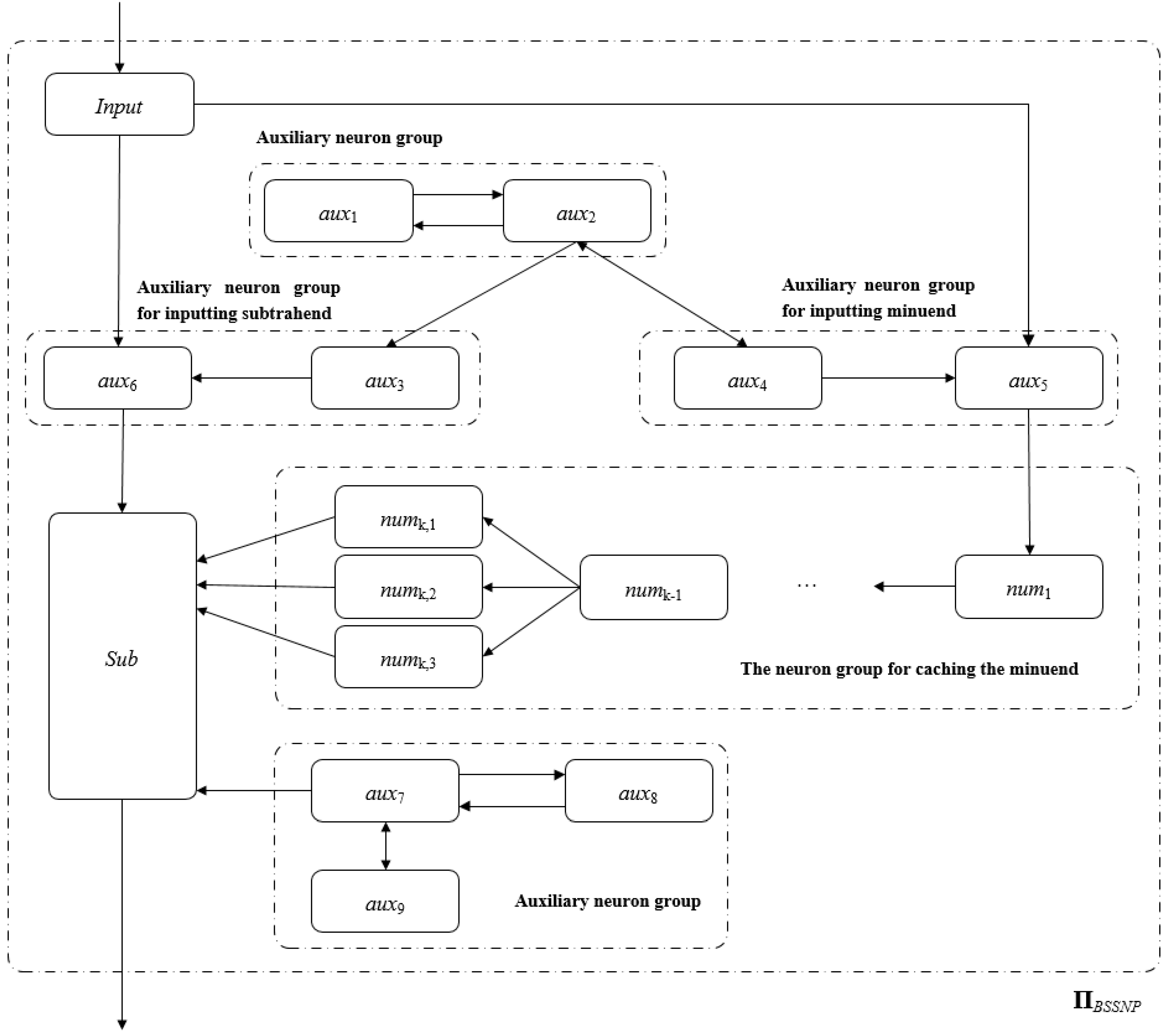
- Input neuron Input. Input receives binary strings from the environment and converts them to spikes in ΠBSSNP.
- Subtractive neuron Sub. The binary strings of the subtrahend and the minuend are subtracted bit by bit in the neuron Sub.
- Auxiliary neuron groups (aux1, aux2, aux7, aux8, aux9). Continuously send a spike to neurons aux3, aux4, and Sub at each time slice.
- Minuend input auxiliary neuron group. The subtrahend is controlled to be accurately input into the minuend cache neuron, and the interference when the subtrahend is input is shielded.
- Minus input auxiliary neuron group. The subtrahend is controlled to be accurately input to the neuron Sub, and the interference when the subtrahend is input is shielded.
- Minuend cache neuron groups. The minuend is cached so that the corresponding binary bits of the minuend and the subtrahend are synchronously sent to the neuron Sub for operation.
- (1)
- t = k + 1, the spike in σnumj (1 ≤ j ≤ k − 1) is sp-xk−j−1, and at the next time slice, σnumk−1 will move to σnumk,1, σnumk,2, σnumk,3 send spikes in σnumk−1, respectively.
- (2)
- σaux7, σaux8 maintain a spike and σaux7 sends a spike to σSub at each time slice. At t = k + 1, there are k spikes in σaux9. There are no spikes in σSub.
- (3)
- When t = k + 2, the minuend is input into the minuend cache neuron group, and the pattern Ck+2 of ΠBSSNP is as shown in Figure 5.
- (4)
- From t = k + 3 to 2k + 2, σSub simultaneously receives sp-xi and sp-yi (0 ≤ i ≤ k − 1) sequentially. Readers can refer to [13] for details of the subtraction operation in σSub.
- (5)
- Starting from time t = k + 4, the environment starts to receive the calculation results in sequence.
- (6)
- t = 2k + 2, there are 2k + 1 spikes in σaux9, and the rule a2k+1→a2 is executed, which will consume 2k + 1 spikes and send two spikes to σaux7.
- (7)
- t = 2k + 3, there is 1 spike in σaux9, three spikes in σaux7, and one spike in σaux8, which will not change after that.
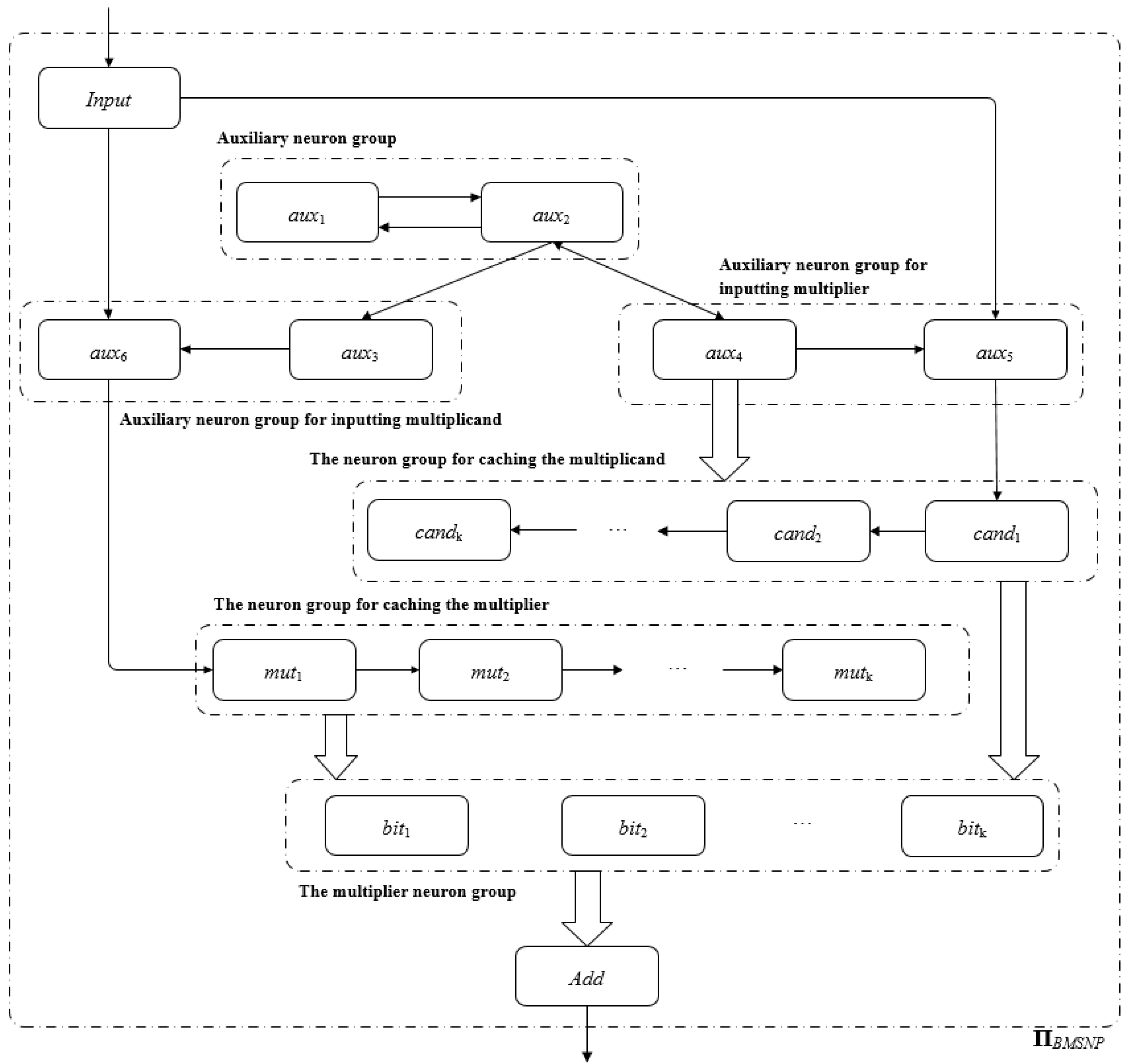
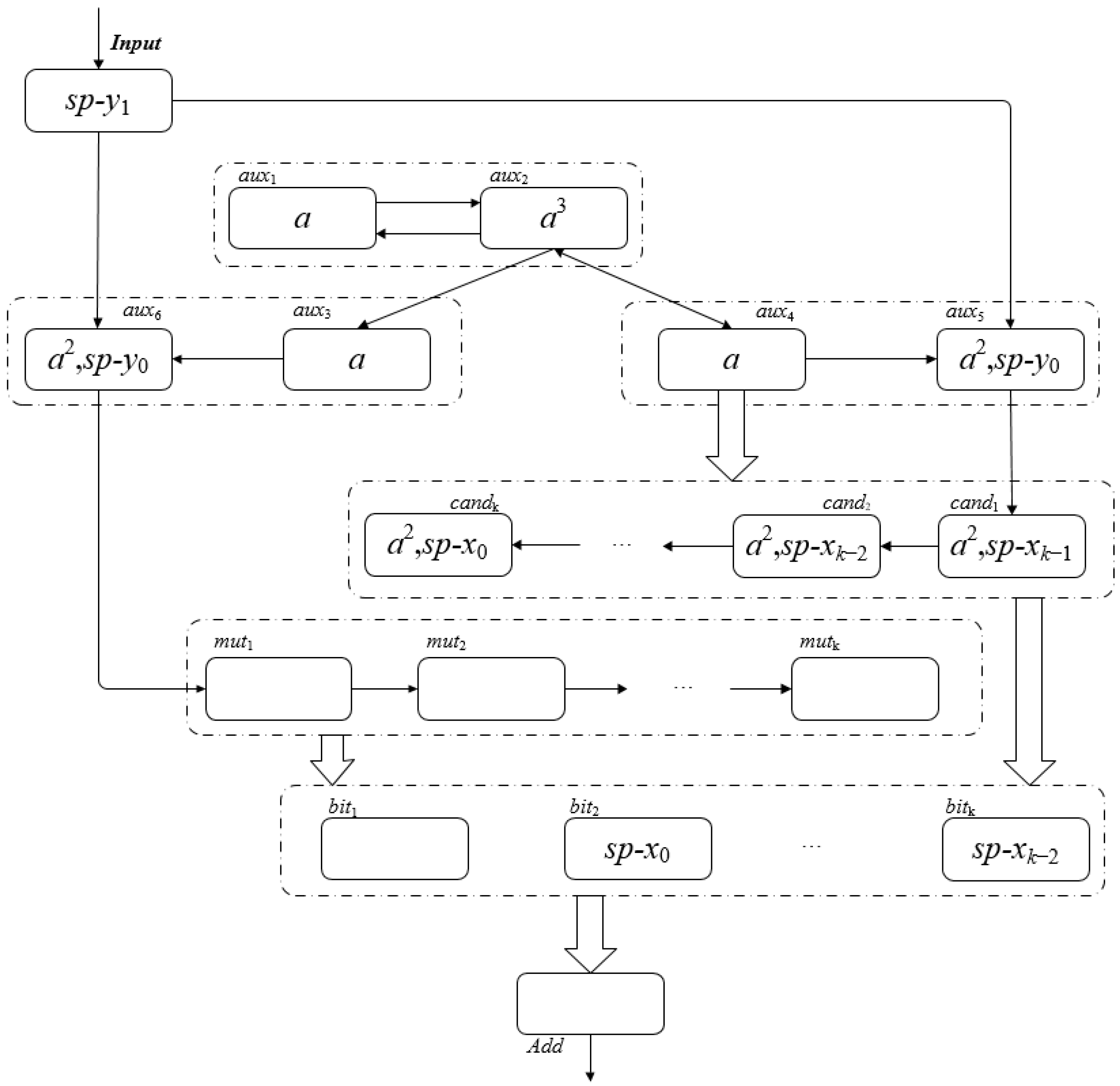
3.3. Binary Multiplication in SNP Systems
- (1)
- Through the input neuron Input, inputting the binary string of the multiplicand from the lowest bit to the highest bit. When the i-th bit (0 ≤ i ≤ k − 1) in the input string is 1, the neuron Input gets one spike; otherwise, it does not get a spike.
- (2)
- After each bit of the multiplicand is input, it is cached in the system. When all bits of the multiplicand are input, store the multiplicand in the multiplicand neuron group and wait for the input of the multiplier. After inputting the highest bit of the multiplicand, the multiplier is entered immediately.
- (3)
- After each bit of the multiplier is input, it is cached in the system and sent to the multiplicand neuron to perform multiplication with the corresponding binary bit of the multiplicand.
- (4)
- The stored multiplicand information in the multiplicand neuron group is not changed by the operation in (3).
- (5)
- Neuron Add calculates a binary bit of the multiplication result at every moment.
- (1)
- O = {a};
- (2)
- σInput = (0,RInput), RInput = {a→a};
- (3)
- σaux1 = (1,Raux1), Raux1 = {a→a};
- (4)
- σaux2 = (1,Raux2), Raux2 = {a→a};
- (5)
- σaux3 = (0,Raux3), Raux3 = {ak→a2};
- (6)
- σaux4 = (0,Raux4), Raux4 = {ak→a2};
- (7)
- σaux5 = (0,Raux5), Raux5 = {a→a; a3/a→λ};
- (8)
- σaux6 = (0,Raux6), Raux6 = {a→λ; a3/a→a};
- (9)
- σcandi = (0,Rcandi), Rcandi = {a→a; a2→λ; a3→a2},;
- (10)
- σmuti = (0,Rmuti), Rmuti = {a→a},;
- (11)
- σbiti = (0,Rbiti), Rbiti = {a→λ; a3/a→a},;
- (12)
- σAdd =(0,RAdd), RAdd = {a2j/aj→λ; a2j+1/aj+1→a},;
- (13)
- syn = {(Input,auxi)|}∪{(aux1,aux2)}∪{(aux2,auxi)|}∪{(aux3,aux6)}∪{(aux4,auxi)|}∪{(aux4,candi)|}∪{(aux5,cand1)}∪{(aux6,mut1)}∪{(candi,candi+1)|}∪{(muti,muti+1) | }∪{(biti,biti+1)|}∪{(candi,bitk-i+1) | }∪{(muti,biti) | }∪{(biti,Add) | };
- (14)
- in = input;
- (15)
- out = Add;
- Input neuron Input. Input receives binary strings from the environment and converts them to spikes in ΠBMSNP.
- Addition neuron Add. The result of multiplying the multiplier by the multiplicand’s bits is summed in the Add neuron.
- Auxiliary neuron groups (aux1, aux2). Continuously send a spike to neurons aux3 and aux4 at each time slice.
- The multiplicand is input to the auxiliary neuron group. Control the multiplicand to be accurately input into the summand buffer neuron, shield the interference during multiplication input, and save the multiplicand in the multiplicand neuron group when the input of the highest bit of the multiplicand is completed.
- Multiply the input auxiliary neuron group. The control multiplier is accurately input into the multiplier cache neuron group, and the interference when the multiplier is input is shielded.
- Group of multiplicand cache neurons. Cache multiplicand.
- Group of multiplier cache neurons. The multiplier is buffered, and each binary bit of the control multiplier is multiplied by the multiplicand.
- Group of multiplicand neurons. The multiplicand is stored, and the multiplication operation of the multiplier and each binary bit of the multiplicand is performed.
- Input the natural number X;
- Compute each bit of Z in parallel while inputting Y;
- Output each bit of Z from low to high in turn.
- (1)
- From t = 0 to t = k + 1, the regular execution of ΠBMSNP and the change of spikes in each neuron include:
- (i)
- σInput accepts sp-xi (0 ≤ i ≤ k − 1) and applies the corresponding rules to send sp-xi to σaux5. During this period, σaux5 can only receive the spikes sent by σInput, and apply the rules to send the received spikes to σcand1 in turn. Similarly, σcandj (1 ≤ j ≤ k − 2) sends the received spikes to σcandj+1 and σbitj respectively.
- (ii)
- σaux6 accepts the spikes sent by σInput, if sp-xi (0 ≤ i ≤ k − 1) = {a}, use the rule a→λ to forget this spike.
- (iii)
- σbitj (1 ≤ j ≤ k − 2) accepts spikes sent by σcandj (1 ≤ j ≤ k − 2) and forgets them using the rule a→λ.
- (iv)
- σaux1 and σaux2 (starting to work at t = 1) each maintain one spike, and σaux3 and σaux4 each maintain k spikes at t = k + 1.
- (v)
- t = k + 1, σaux3 use the rule ak→a2 to send two spikes to σaux6, and σaux4 use the rule ak→a2 to send two spikes to σaux5 and σcandj (1 ≤ j ≤ k) respectively. σInput accepts sp-y0 and sends sp-y0 to σaux6 according to the corresponding rules.
- (vi)
- There is no spike in σadd, σmuti (1 ≤ i ≤ k).
- (2)
- t = k + 2, the rule execution of ΠBMSNP and the change of spikes in each neuron include:
- (i)
- σInput accepts sp-y1 and sends sp-y0 to σaux5, σaux6 respectively. σaux5 sends sp-xk−1 to σcand1 while receiving sp-y0 and {a2} from σaux4. σcandj (1 ≤ j ≤ k−1) accepts sp-xk-j and sends sp-xk-j−1, and σcandk accepts sp-x0. σcandj (1 ≤ j ≤ k) receives the two spikes sent by σaux4, and σcandj(1 ≤ j ≤ k) use the rule a3→a2 or a→λ to send sp-xj−1 to σbitj.
- (ii)
- σaux6 forgets sp-xk−1 accepts both sp-y0 (from σInput) and {a2} (from σaux3).
- (iii)
- σaux1 holds one spike, σaux2 gets three spikes (one spike from σaux1, two spikes from σaux4), σaux3 and σaux4 hold one spike.
- (iv)
- There is no spike in σadd, σmuti (1 ≤ i ≤ k).At this point, the multiplicand has been input into the multiplicand cache neuron group, and we can get Figure 8, which shows the spikes contained in each neuron in the pattern Ck+2.
- (3)
- t = k + 3, the multiplicand has been input into the multiplicand neuron group, and the spike changes in each neuron of ΠBMSNP are shown in Figure 9:
- (i)
- σInput accepts sp-y2 and sends sp-y1 to σaux5 and σaux6, respectively.
- (ii)
- There are no spikes in σaux1 and four spikes in σaux4.
- (iii)
- σaux3 and σaux4 maintain one spike each.
- (iv)
- σaux5 receives the sp-y1 sent by σInput, and use the corresponding rules in σaux5 to forget sp-y0.
- (v)
- σaux6 receives the sp-y1 sent by σInput and applies the corresponding rules in σaux6 to send sp-y0 to σmut1.
- (vi)
- σmut1 receives sp-y0 sent by σaux6.
- (vii)
- There is no spike in σcandi (1 ≤ i ≤ k), σmutj (2 ≤ j ≤ k).
- (viii)
- sp-xi−1 is received in σbiti (1 ≤ i ≤ k).
- (4)
- From t = k + 4 to 3k + 5, the rule execution of ΠBMSNP and the change of spikes in each neuron include:
- (i)
- σInput sequentially accepts sp-yj (3 ≤ j ≤ k − 1) and simultaneously use the rules to send sp-yj−1 to σaux5 and σaux6.
- (ii)
- When the number of spikes in σaux5 is 3, the rule a3/a→λ is activated and consumes one spike, so there will always be two spikes in σaux5 and no spikes will be sent.
- (iii)
- There is no spike in σcandi (1 ≤ i ≤ k).
- (iv)
- σaux6 sends sp-yj (1 ≤ j ≤ k − 1) to σmut1 sequentially.
- (v)
- σmuti (1 ≤ i ≤ k) sends sp-yt+i-(k+5) to σmuti+1 and σbiti respectively. Where t is the current moment of ΠBMSNP. If t + i − (k + 5) < 0, it means that there is no spike in σmuti, and no spike will be sent to σmuti+1 and σbiti.
- (vi)
- t = k + 4, σbit1 receives the sp-y0 sent by σmut1, and performs the product operation of sp-y0 and sp-x0 in σbit1, and sends the operation result to σAdd at the next time slice. Note that after the operation in σbit1, sp-x0 is still stored in the neuron.
- (vii)
- t = k + 5, σbit1 receives the sp-y1 sent by σmut1, performs the product operation of sp-y1 and sp-x0 in σbit1, and sends the operation result to σAdd at the next time slice.σAdd receives the product operation result of sp-y0 and sp-x0, namely z0, and sends z0 to the environment at the next time slice.
- (viii)
- t = k + 6, z0 is received in the environment.σAdd is summing the following operation results: sp-y0 × sp-x1, sp-y1 × sp-x0, the summation result is z1, and the carry is kept in σAdd.The ongoing multiplication operation of ΠBMSNP: sp-y0 × sp-x2, sp-y1 × sp-x1, sp-y2 × sp-x0 they will be sent to σAdd for summing operation at the next time, and the operation result is z2.
- (ix)
- Similarly, t = k + 7, z1 is received in the environment.t = k + 8, z2 is received in the environment.t = k + i (9 ≤ i ≤ 2k + 3), zi−6 is received in the environment.t = 3k + 4, z2k−2 is received in the environment.Considering that a carry may occur when operating z2k−2, the system reaches the termination configuration at t = 3k + 5.Based on the above description, readers can verify that, for k ≥ 2, the SNPS multiplication constructed above can correctly solve the product of two natural numbers with a binary length of k, and the proof is complete. □
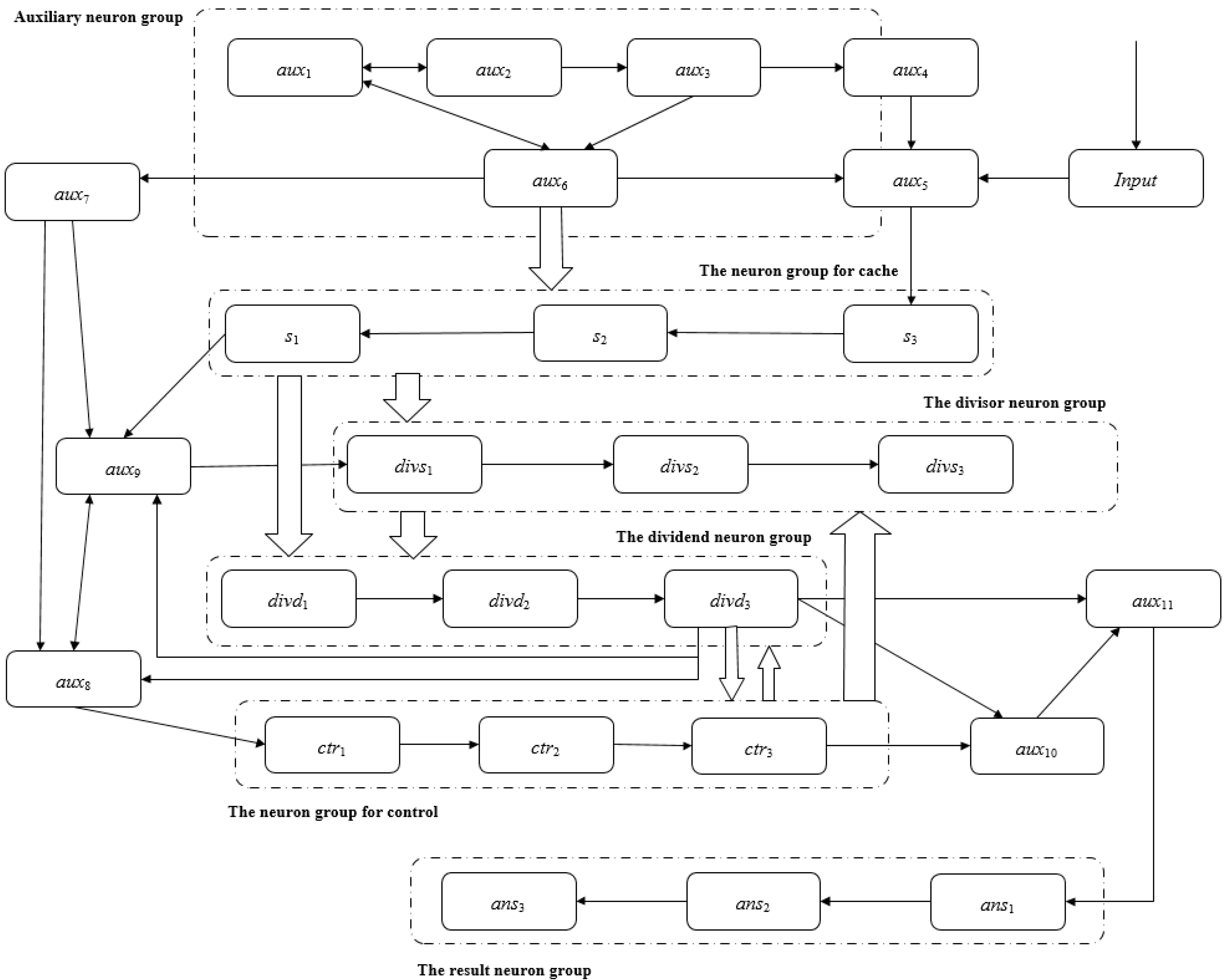
3.4. Binary Division in SNP Systems
- (1)
- Through the input neuron, input the binary string of the dividend from the lowest bit to the highest bit. When the i-th bit (0 ≤ i ≤ k − 1) in the input string is 1, the neuron input gets one spike; otherwise, it does not get one spike.
- (2)
- After each digit of the dividend is input, it will be cached in the system. When all digits of the dividend are input, the dividend is stored in the dividend neuron group. Wait for the input of the divisor. Input the divisor immediately after the highest digit of the dividend is input.
- (3)
- After the divisor input is completed, save the divisor in the divisor neuron group. After the highest digit of the divisor is input, the control neuron group immediately sends the divisor to the dividend neuron group for subtraction. The stored dividend information in the dividend neuron group will be changed due to the subtraction operation.
- (4)
- For each subtraction operation, send a spike to the resulting neuron group.
- (5)
- Continue to carry out (4) in parallel until the highest bit of the dividend neuron group sends a borrow message to the control neuron group.
- (1)
- O = {a};
- (2)
- σInput = (0,RInput), RInput = {a→a; a3→a; a5→λ};
- (3)
- σaux1 = (1,Raux1), Raux1 = {a→a};
- (4)
- σaux2 = (1,Raux2), Raux2 = {a→a};
- (5)
- σaux3 = (0,Raux3), Raux3 = {a2k−1→a};
- (6)
- σaux4 = (0,Raux4), Raux4 = {a→a};
- (7)
- σaux5 = (0,Raux5), Raux5 = {a→a; a2→λ; a3→a; a5→λ};
- (8)
- σaux6 = (0,Raux6), Raux6 = {ak→a2; ak+1→a3};
- (9)
- σaux7 = (0,Raux7), Raux7 = {a2→λ; a3→a3};
- (10)
- σaux8 = (2,Raux8), Raux8 = {a4→λ} ∪ {ai→a5,} ∪ {a9→λ};
- (11)
- σaux9 = (0,Raux9), Raux9 = {ai→λ | } ∪ {ai→a5 | ; a9→λ};
- (12)
- σaux10 = (0,Raux10), Raux10 = {a4→λ; a5→a; a9→λ};
- (13)
- σaux11 = (0,Raux11), Raux11 = {a→a; a4→λ; a5→λ};
- (14)
- σsi = (0,Rsi), Rsi = {a→a; a2→λ; a3→a2; a4→a3} ∪ {aj→λ | } |;
- (15)
- σdivs1 = (0,Rdivs1), Rdivs1 = {aj→λ | } ∪ {a5→a4; a8/a5→a5}
- (16)
- σdivsi = (0,Rdivsi), Rdivsi = {aj→λ | } ∪ {aj→a4 | } ∪ {aj/a5→a5 | } | ;
- (17)
- σctri = (0,Rctri), Rctri = {a4→λ; a5→a; a9→λ} | ;
- (18)
- σdivd1 = (0,Rdivd1), Rdivd1 = {a→λ; aj/a→λ | } ∪ {aj/a5→λ | } ∪ {a8/a4→a4; a10/a8→λ};
- (19)
- σdivdi = (0,Rdivdi), Rdivdi = {a→λ; aj/a→λ | ; aj/a5→λ,; a8/a4→a4; a10/a8→λ; a11/a7→a4; aj/a10→a4 | ; a13/a11→λ}, ;
- (20)
- σansi = (0,Ransi), Ransi = {a2→a}, ;
- (21)
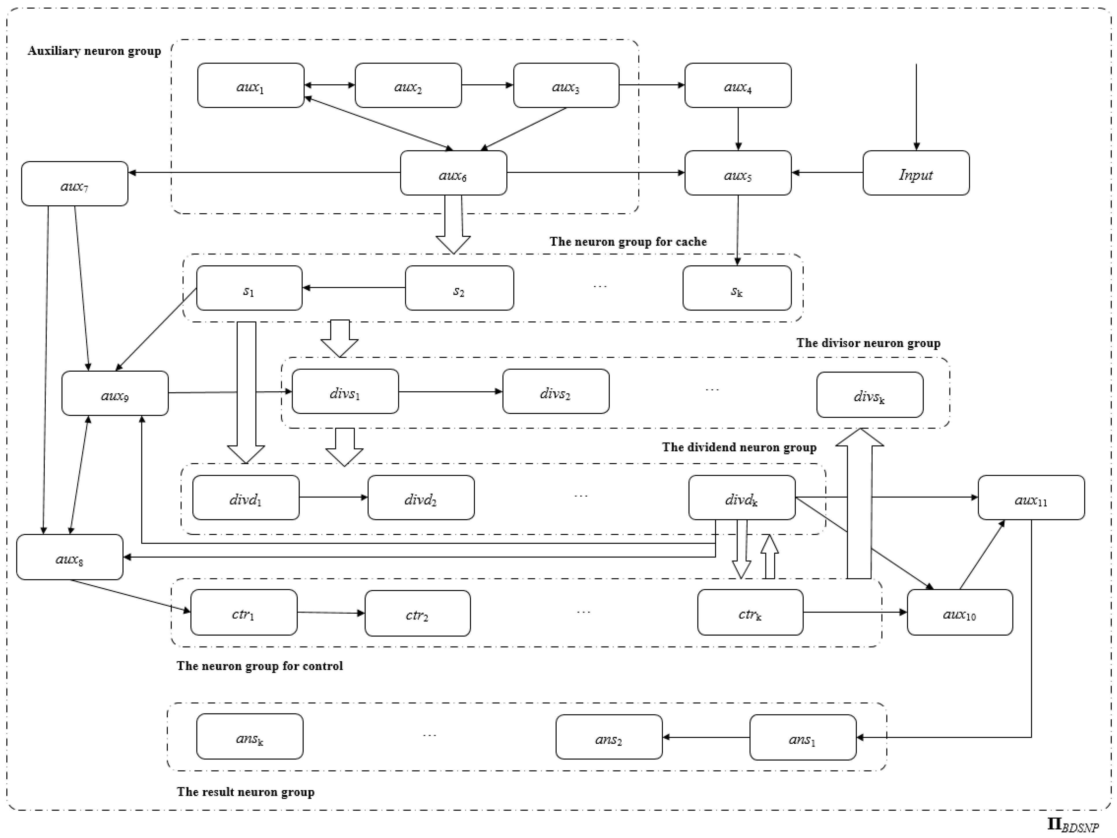
- syn = {(Input,aux5)}∪{(aux1,auxi)|}∪{(aux2,auxi)|}∪{(aux3,auxi)|}∪{(aux4,aux5)}∪{(aux5,sk)}∪{(aux6,auxi)|}∪{(aux6,si)|}∪{(aux7,auxi)|}∪{(aux8,aux9)}∪{(aux8,ctr1)}∪{(aux9,aux8)}∪{(aux9,divs1)}∪{(aux10,aux11)}∪{(aux11,ans1)}∪{(s1,aux9)}∪{(si+1,si)|}∪{(si,divdi)|}∪{(si,divsi)|}∪{(divsi,divsi+1)|}∪{(divsi,divdi)|}∪{(ctri,divsi+1)|}∪{(ctri,ctri+1)|}∪{(ctri,divdi)|}∪{(ctrk,aux11)}∪{(divdi,divdi+1)|}∪{(divdk,ctri)|}∪{(divdk,auxi)|}∪{(ansi,ansi+1)|};
- (22)
- in = input;
- (23)
- out = ansi|;
- Input neuron Input. Input receives binary strings from the environment and converts them to spikes in ΠBDSNP.
- Cache groups of neurons. Temporarily cache the dividend and the divisor. After the highest digit of the dividend is input into the system, the auxiliary neuron will save the dividend in the dividend neuron group. After the highest digit of the divisor is input into the system, the auxiliary neuron will save the divisor in the divisor neuron group.
- Auxiliary neuron group. The control dividend and divisor are stored in the dividend neuron group and the divisor neuron group, respectively.
- Dividend neuron group. Save the dividend, perform the operation of subtracting the divisor, and send a signal to the control neuron group if the subtraction is not enough.
- Divisor group of neurons. Save the divisor, and send the divisor to the dividend neuron group for subtraction.
- Groups of control neurons. Control the process of subtracting the dividend and the divisor, and stop when the result of the subtraction operation is less than the divisor.
- Resulting neuron groups. Counts the number of subtraction operations performed.
- Input dividend X and divisor Y;
- Loop controls the dividend to subtract the divisor until the dividend is smaller than the divisor;
- Count the number of subtractions, and convert the result into a binary form.
- (1)
- t = 0, start sending the corresponding spike sp-x0 of the lowest bit x0 of X to σInput.
- (2)
- From t = 1 to t = k, the regular execution of ΠBDSNP and the change of spikes in each neuron include:
- (i)
- σInput accepts sp-xi (0 ≤ i ≤ k −1 ) and use the corresponding rules to send sp-xi to σaux5. During this period, σaux5 will only receive the spikes sent by σInput, and use the rules to send the received spikes to σsk in turn. Similarly, σsj (3 ≤ j ≤ k) sends the received spikes to σsj−1 in sequence.
- (ii)
- σaux1 and σaux2 maintain one spike each.
- (iii)
- t = k, σaux3 and σaux6 each contain k − 1 spikes.
- (iv)
- There are no spikes in σs1, σs2, σauxi |, σdivsi, σctri, σdivdi, σansi |.
- (3)
- t = k + 1, the rule execution of ΠBDSNP and the change of spikes in each neuron include:
- (i)
- σInput accepts sp-y0 and sends sp-y0 to σaux5 according to the corresponding rules. σaux5 accepts sp-xk−1 and sends sp-xk−2, σsj (3 ≤ j ≤ k) accepts sp-xk−j and sends sp-xk−j−1, and σs2 accepts sp-x0.
- (ii)
- There are k spikes in σaux3
- (iii)
- There are k spikes in σaux6, and the rule ak→a2 will be used to send two spikes each to σauxi| and σsj (1 ≤ j ≤ k).
- (4)
- t = k + 2, the rule execution of ΠBDSNP and the change of spikes in each neuron include:
- (i)
- σInput accepts sp-y1 and sends sp-y0 to σaux5. σaux5 sends sp-xk−1 to σsk while receiving sp-y0 and {a2} from σaux6. σsj (1 ≤ j ≤ k) receives sp-xj−1 and {a2} from σaux6.
- (ii)
- There are three spikes in σaux1 and k + 1 spikes in σaux3.
- (iii)
- There is one spike in σaux6. There are two spikes in σaux7, and we use the rule a2→λ to forget these two spikes.At this time, the dividend has been input into the cache neuron group, and they will be sent to the dividend neuron group for storage at the next moment.
- (5)
- t = k + 3, σdivdj (1 ≤ j ≤ k) receives sp-xj−1, at this time sp-xj−1 = {a2} means xj−1 is 1, sp-xj−1 = {λ} means that xj−1 is 0.
- (6)
- From t = k + 4 to t = 2k + 3, the regular execution of ΠBDSNP and the change of spikes in each neuron include:
- (i)
- σsj (1 ≤ j ≤ k) sends the received spikes to σsj−1 in sequence.
- (ii)
- t = 2k, there are 2k−1 spikes in σaux3, the rule a2k−1→a executes, sending one spike to σaux4.
- (iii)
- t = 2k + 1, there are k + 1 spikes in σaux6, the rule ak+1→a3 is executed, and they are sent to σauxi| and σsj (1 ≤ j ≤ k) respectively two spikes.
- (iv)
- When t = 2k + 2, σaux5 receives three spikes from σaux6 and one spike from σaux4.There are four spikes in σaux1.There are three spikes in σaux7.σsj (1 ≤j ≤ k) will receive three spikes from sp-yj−1 and σaux6. σsj (1 ≤ j ≤k) will send two spikes to σdivdj and σaux9.At this point, the divisors have been entered into the cache neuron group, and they will be sent to the divisor neuron group for storage at the next moment. sp-yj−1 (1 ≤ j ≤ k) = {a3} means that xj−1 is 1, and sp-xj−1 = {λ} means that xj−1 is 0.
- (v)
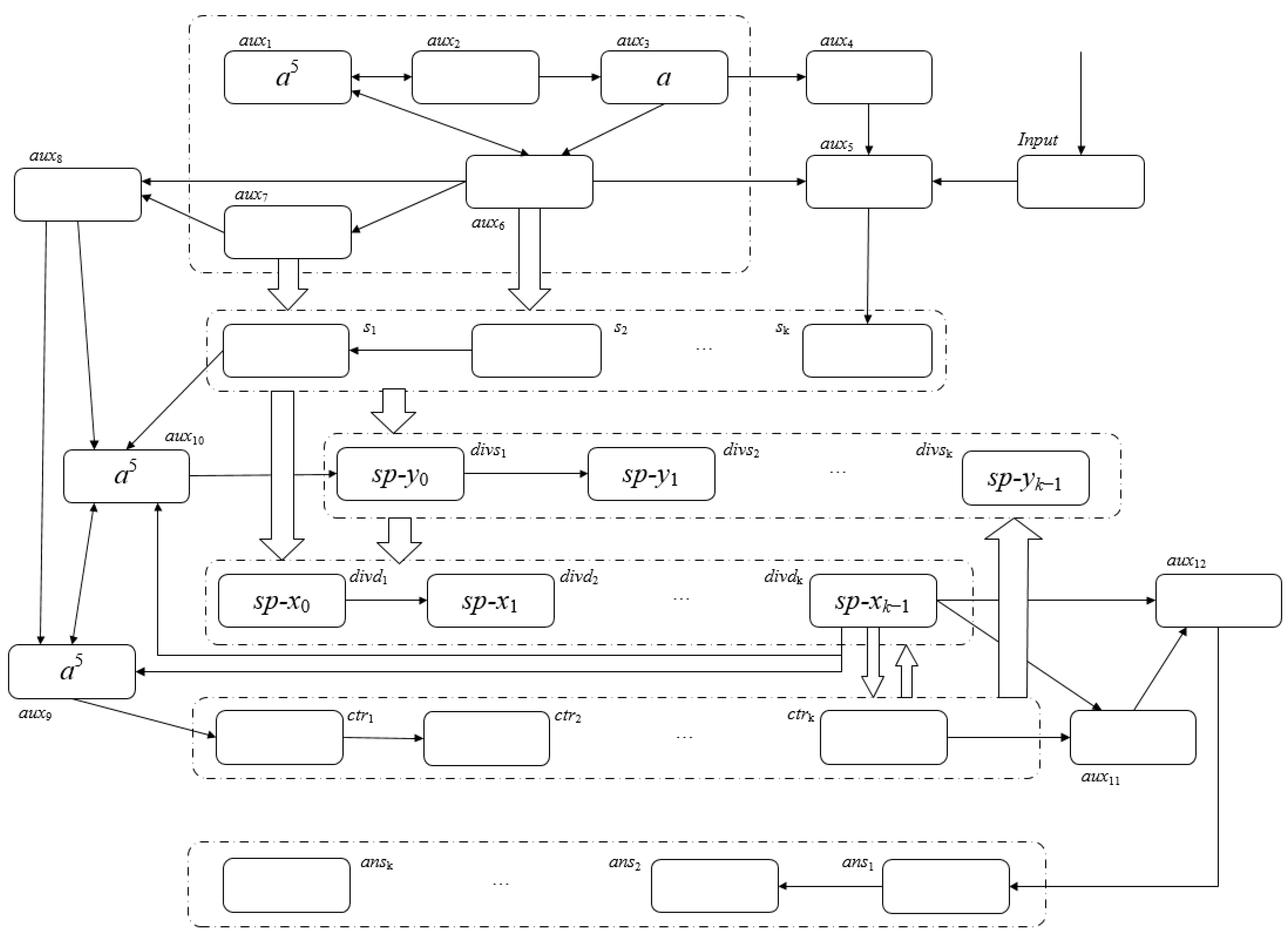
- t = 2k + 3, σdivsj (1 ≤ j ≤ k) receives the sp-yj−1 sent by sj, and the divisor is stored in the divisor neuron group.There are five spikes in σaux9 (three from σaux7 and two from itself).There are five spikes in σaux10 (three from σaux7 and two from σs1).There are no spikes in σctrj (1 ≤ j ≤ k).σdivdj (1 ≤ j ≤ k), receiving two spikes sent by sj, after executing the corresponding rules in σdivdj, sp-xj−1 = {a4} it means that xj−1 is 1, and sp-xj−1 = {a2} means that xj−1 is 0.We can obtain Figure 12 now that both the dividend and the divisor have been entered into the system, which shows the spikes contained within the individual neurons in the pattern C2k+3.
- (7)
- After t = 2k + 4, the regular execution of ΠBDSNP and the change of spikes in each neuron include:
- (i)
- t = 2k + 4, σdivs1 receives five spikes from σaux10, σdivs1 receives five spikes from σaux9, and prepares to send sp-y0 to σdivs1. σctr1 sends one spike to σdivs2 and σdivd1 and σctr2, respectively.
- (ii)
- t = 2k + 5, the difference operation between sp-x0 and sp-y0 is being performed in σdivd1, and the operation result is kept in σdivd1. If a borrow occurs, four spikes will be sent to σdivd2 to participate in the calculation of sp-x1 and sp-y1 at the next time slice.σdivs2 receives four spikes from σdivs1 and one spike from σctr1, and prepares to send sp-y1 to σdivs2. σctr2 sends one spike to σdivs3 and σdivd2 and σctr3, respectively.
- (iii)
- t = 2k + 6, the difference operation between sp-x1 and sp-y1 is being performed in σdivd2, and the operation result is kept in σdivd2. If a borrow occurs, four spikes will be sent to σdivd3 to participate in the calculation of sp-x2 and sp-y2 at the next time slice.
- (iv)
- Similarly, it is not difficult to verify that t = 3k + 4, the difference operation of sp-xk−1 and sp-yk−1 is going on in σdivdk. So far, the first subtraction operation is completed. If σdivdk does not send 4 spikes to σaux12 (X ≥ Y), σaux11 will send one spike to σaux12, and σaux12 will send this spike to σans1 at the next time slice.
- (v)
- Because the neurons of σdivdi(1 ≤ i ≤ k) work in parallel, when t = 3k + 5, the second subtraction operation is completed. If σdivdk does not send four spikes to σaux12 (X ≥ Y), σaux11 will send one spike to σaux12, and σaux12 will send this spike to σans1 at the next time slice.
- (vi)
- The system will keep running until σdivdk sends four spikes to σaux12, indicating that the current dividend is smaller than the divisor.
4. Comparison of Arithmetic Operations Realized by Various SNP Systems
5. Conclusions and Future Work
Author Contributions
Funding
Institutional Review Board Statement
Informed Consent Statement
Data Availability Statement
Conflicts of Interest
References
- Păun, G. Computing with membranes. J. Comput. Syst. Sci. 2000, 61, 108–143. [Google Scholar] [CrossRef]
- Păun, G. A Quick Introduction to Membrane Computing. J. Logic. Algebr. Progr. 2010, 79, 291–294. [Google Scholar] [CrossRef]
- Atanasiu, A. Arithmetic with Membranes. In Proceedings of the Workshop on Multiset Processing, Argeş, Romania, 21–25 August 2000. [Google Scholar]
- Ciobanu, G. A Programming Perspective of the Membrane Systems. Int. J. Comput. Commun. 2006, 1, 13. [Google Scholar] [CrossRef]
- Guo, P.; Chen, J. Arithmetic Operation in Membrane System. In Proceedings of the 2008 International Conference on BioMedical Engineering and Informatics, Sanya, China, 27–30 May 2008. [Google Scholar]
- Guo, P.; Zhang, H. Arithmetic Operation in Single Membrane. In Proceedings of the 2008 International Conference on Computer Science and Software Engineering, Wuhan, China, 12–14 December 2008. [Google Scholar]
- Guo, P.; Luo, M. Signed Numbers Arithmetic Operation in Multi-Membrane. In Proceedings of the 2009 First International Conference on Information Science and Engineering, Nanjing, China, 26–28 December 2009. [Google Scholar]
- Guo, P.; Liu, S.J. Arithmetic Expression Evaluation in Membrane Computing with Priority. Adv. Mater. Res. 2011, 225–226, 1115–1119. [Google Scholar] [CrossRef]
- Guo, P.; Chen, H.Z.; Zheng, H. Arithmetic Expression Evaluations with Membranes. Chin. J. Electron 2014, 23, 55–60. [Google Scholar]
- Guo, P.; Chen, H.Z. Arithmetic Expression Evaluation by P Systems. Appl. Math. Inform. Sci. 2014, 7, 549–553. [Google Scholar] [CrossRef]
- Guo, P.; Zhang, H.; Chen, H.Z.; Chen, J.X. Fraction Arithmetic Operations Performed by P Systems. Chin. J. Electron 2013, 22, 690–694. [Google Scholar]
- Zhang, X.; Liu, Y.; Luo, B.; Pan, L. Computational Power of Tissue P Systems for Generating Control Languages. Inf. Sci. 2014, 278, 285–297. [Google Scholar] [CrossRef]
- Ionescu, M.; Paun, G.; Yokomori, T. Spiking Neural P Systems. Fund. Inform. 2006, 71, 279–308. [Google Scholar]
- Luo, Y.; Zhao, Y.; Chen, C. Homeostasis Tissue-Like P Systems. IEEE Trans. NanoBiosci. 2021, 20, 126–136. [Google Scholar] [CrossRef]
- Păun, G. Spiking Neural P Systems. In Power and Efficiency; Springer: Berlin/Heidelberg, Germany, 2007; pp. 153–169. [Google Scholar]
- Chen, H.; Freund, R.; Ionescu, M.; Paun, G.; Perez-Jimenez, M.J. On String Languages Generated by Spiking Neural P Systems. Fund. Inform. 2007, 75, 141–162. [Google Scholar]
- Chen, H.; Ionescu, M.; Ishdorj, T.-O.; Păun, A.; Păun, G.; Pérez-Jiménez, M.J. Spiking Neural P Systems with Extended Rules: Universality and Languages. Nat. Comput. 2008, 7, 147–166. [Google Scholar] [CrossRef]
- Metta, V.P.; Krithivasan, K.; Garg, D. Computability of spiking neural P systems with anti-spikes. New. Math. Nat. Comput. 2012, 8, 283–295. [Google Scholar] [CrossRef]
- Păun, A.; Păun, G. Small Universal Spiking Neural P Systems. BioSystems 2007, 90, 48–60. [Google Scholar] [CrossRef]
- Song, T.; Pan, L.; Păun, G. Spiking Neural P Systems with Rules on Synapses. Theor. Comput. Sci. 2014, 529, 82–95. [Google Scholar] [CrossRef]
- Song, T.; Pan, L.; Păun, G. Asynchronous Spiking Neural P Systems with Local Synchronization. Inf. Sci. 2013, 219, 197–207. [Google Scholar] [CrossRef]
- Wang, J.; Hoogeboom, H.J.; Pan, L.; Păun, G.; Pérez-Jiménez, M.J. Spiking Neural P Systems with Weights. Neural. Comput. 2010, 22, 2615–2646. [Google Scholar] [CrossRef]
- Liu, X.; Ren, Q. Spiking Neural Membrane Computing Models. Processes 2021, 9, 733. [Google Scholar] [CrossRef]
- Pan, L.; Păun, G.; Pérez-Jiménez, M.J. Spiking Neural P Systems with Neuron Division and Budding. Sci. China Inf. Sci. 2011, 54, 1596–1607. [Google Scholar] [CrossRef]
- Xue, J.; Liu, X. Solving Directed Hamilton Path Problem in Parallel by Improved SN P System. In Proceedings of the International Conference on Pervasive Computing and the Networked World, Istanbul, Turkey, 28–30 November 2012; pp. 689–696. [Google Scholar] [CrossRef]
- Rong, H.; Yi, K.; Zhang, G.; Dong, J.; Paul, P.; Huang, Z. Automatic Implementation of Fuzzy Reasoning Spiking Neural P Systems for Diagnosing Faults in Complex Power Systems. Complexity 2019, 2019, 2635714. [Google Scholar] [CrossRef]
- Pan, L.; Păun, G. Spiking Neural P Systems with Anti-Spikes. Int. J. Comput. Commun. 2009, 4, 273. [Google Scholar] [CrossRef]
- Zeng, X.; Song, T.; Zhang, X.; Pan, L. Performing Four Basic Arithmetic Operations with Spiking Neural P Systems. IEEE Trans. NanoBiosci. 2012, 11, 366–374. [Google Scholar] [CrossRef]
- Naranjo, G.; Ángel, M.; Leporati, A. Performing Arithmetic Operations with Spiking Neural P Systems. In Proceedings of the Seventh Brainstorming, Sevilla, Spain, 27 February 2009. [Google Scholar]
- Zhang, X.-Y.; Zeng, X.-X.; Pan, L.-Q.; Luo, B. A spiking neural P system for performing multiplication of two arbitrary natural numbers. Jisuanji Xuebao 2009, 32, 2362–2372. [Google Scholar]
- Peng, X.-W.; Fan, X.-P.; Liu, J.-X.; Wen, H. Spiking Neural P Systems for Performing Signed Integer Arithmetic Operations. J. Chin. Comput. Syst. 2013, 34, 360–364. [Google Scholar]
- Zhang, G.; Rong, H.; Paul, P.; He, Y.; Neri, F.; Pérez-Jiménez, M.J. A Complete Arithmetic Calculator Constructed from Spiking Neural P Systems and Its Application to Information Fusion. Int. J. Neural. Syst. 2021, 31, 2050055. [Google Scholar] [CrossRef]
- Păun, G.; Pérez-Jiménez, M.J.; Rozenberg, G. Spike trains in spiking neural P systems. Int. J. Found. Comput. Sci. 2006, 17, 975–1002. [Google Scholar] [CrossRef]
- Pan, L.; Zeng, X.; Zhang, X. Time-Free Spiking Neural P Systems. Neural. Comput. 2011, 23, 1320–1342. [Google Scholar] [CrossRef]
- Liu, X.; Li, Z.; Liu, J.; Liu, L.; Zeng, X. Implementation of Arithmetic Operations with Time-Free Spiking Neural P Systems. IEEE Trans. NanoBiosci. 2015, 14, 617–624. [Google Scholar] [CrossRef] [PubMed]
- Wang, H.; Zhou, K.; Zhang, G. Arithmetic Operations with Spiking Neural P Systems with Rules and Weights on Synapses. Int. J. Comput. Commun. 2018, 13, 574. [Google Scholar] [CrossRef]
- Peng, X.; Fan, X.; Liu, J.; Wen, H.; Liang, W. Spiking Neural P Systems with Anti-Spikes for Performing Balanced Ternary Logic and Arithmetic Operations. J. Chin. Comput. Syst. 2013, 34, 832–836. [Google Scholar] [CrossRef]


| Step t | Input | aux1 | aux2 | aux3 | aux4 | aux5 | aux6 | num1 | num2 | num3 | Add | Output |
|---|---|---|---|---|---|---|---|---|---|---|---|---|
| 0 | - | 1 | 1 | 0 | 0 | 0 | 0 | 0 | 0 | 0 | 0 | - |
| 1 | 1 | 1 | 1 | 0 | 0 | 0 | 0 | 0 | 0 | 0 | 0 | - |
| 2 | 1 | 1 | 1 | 1 | 1 | 1 | 1 | 0 | 0 | 0 | 0 | - |
| 3 | 1 | 1 | 1 | 2 | 2 | 1 | 1 | 1 | 0 | 0 | 0 | - |
| 4 | 1 | 1 | 1 | 3 | 3 | 1 | 1 | 1 | 1 | 0 | 0 | - |
| 5 | 0 | 1 | 3 | 1 | 1 | 3 | 3 | 1 | 1 | 1 | 0 | - |
| 6 | 1 | 0 | 4 | 1 | 1 | 2 | 2 | 0 | 1 | 1 | 2 | - |
| 7 | - | 0 | 4 | 1 | 1 | 3 | 3 | 0 | 0 | 1 | 2 | 0 |
| 8 | - | 0 | 4 | 1 | 1 | 2 | 2 | 0 | 0 | 0 | 3 | 0 |
| 9 | - | 0 | 4 | 1 | 1 | 2 | 2 | 0 | 0 | 0 | 1 | 1 |
| 10 | - | 0 | 4 | 1 | 1 | 2 | 2 | 0 | 0 | 0 | 0 | 1 |
| Step t | Input | aux1 | aux2 | aux3 | aux4 | aux5 | aux6 | aux7 | aux8 | aux9 | num1 | num2 | num3, i (i = 1,2,3) | Sub | Output |
|---|---|---|---|---|---|---|---|---|---|---|---|---|---|---|---|
| 0 | - | 1 | 1 | 0 | 0 | 0 | 0 | 1 | 1 | 0 | 0 | 0 | 0 | 0 | - |
| 1 | 1 | 1 | 1 | 0 | 0 | 0 | 0 | 1 | 1 | 0 | 0 | 0 | 0 | 0 | - |
| 2 | 0 | 1 | 1 | 1 | 1 | 1 | 1 | 1 | 1 | 1 | 0 | 0 | 0 | 1 | - |
| 3 | 1 | 1 | 1 | 2 | 2 | 0 | 1 | 1 | 1 | 2 | 1 | 0 | 0 | 1 | - |
| 4 | 0 | 1 | 1 | 3 | 3 | 1 | 1 | 1 | 1 | 3 | 0 | 1 | 0 | 1 | - |
| 5 | 1 | 1 | 3 | 1 | 1 | 2 | 2 | 1 | 1 | 4 | 1 | 0 | 1 | 1 | - |
| 6 | 0 | 0 | 4 | 1 | 1 | 3 | 3 | 1 | 1 | 5 | 0 | 1 | 0 | 4 | - |
| 7 | - | 0 | 4 | 1 | 1 | 2 | 2 | 1 | 1 | 6 | 0 | 0 | 1 | 2 | 1 |
| 8 | - | 0 | 4 | 1 | 1 | 2 | 2 | 1 | 1 | 7 | 0 | 0 | 0 | 5 | 1 |
| 9 | - | 0 | 4 | 1 | 1 | 2 | 2 | 3 | 1 | 1 | 0 | 0 | 0 | 1 | 0 |
| Step t | Input | aux1 | aux2 | aux3 | aux4 | aux5 | aux6 | cand1 | cand2 | cand3 | mut1 | mut2 | mut3 | bit1 | bit2 | bit3 | Add | Output |
|---|---|---|---|---|---|---|---|---|---|---|---|---|---|---|---|---|---|---|
| 0 | - | 1 | 1 | 0 | 0 | 0 | 0 | 0 | 0 | 0 | 0 | 0 | 0 | 0 | 0 | 0 | 0 | - |
| 1 | 1 | 1 | 1 | 0 | 0 | 0 | 0 | 0 | 0 | 0 | 0 | 0 | 0 | 0 | 0 | 0 | 0 | - |
| 2 | 1 | 1 | 1 | 1 | 1 | 1 | 1 | 0 | 0 | 0 | 0 | 0 | 0 | 0 | 0 | 0 | 0 | - |
| 3 | 1 | 1 | 1 | 2 | 2 | 1 | 1 | 1 | 0 | 0 | 0 | 0 | 0 | 0 | 0 | 0 | 0 | - |
| 4 | 1 | 1 | 1 | 3 | 3 | 1 | 1 | 1 | 1 | 0 | 0 | 0 | 0 | 0 | 0 | 0 | 0 | - |
| 5 | 0 | 1 | 3 | 1 | 1 | 3 | 3 | 3 | 3 | 3 | 0 | 0 | 0 | 0 | 0 | 0 | 0 | - |
| 6 | 1 | 0 | 4 | 1 | 1 | 2 | 2 | 0 | 0 | 0 | 1 | 0 | 0 | 2 | 2 | 2 | 0 | - |
| 7 | - | 0 | 4 | 1 | 1 | 3 | 3 | 0 | 0 | 0 | 0 | 1 | 0 | 3 | 2 | 2 | 0 | - |
| 8 | - | 0 | 4 | 1 | 1 | 2 | 2 | 0 | 0 | 0 | 1 | 0 | 1 | 2 | 3 | 2 | 1 | - |
| 9 | - | 0 | 4 | 1 | 1 | 2 | 2 | 0 | 0 | 0 | 0 | 1 | 0 | 3 | 2 | 3 | 1 | 1 |
| 10 | - | 0 | 4 | 1 | 1 | 2 | 2 | 0 | 0 | 0 | 0 | 0 | 1 | 2 | 3 | 2 | 2 | 1 |
| 11 | - | 0 | 4 | 1 | 1 | 2 | 2 | 0 | 0 | 0 | 0 | 0 | 0 | 2 | 2 | 3 | 2 | 0 |
| 12 | - | 0 | 4 | 1 | 1 | 2 | 2 | 0 | 0 | 0 | 0 | 0 | 0 | 2 | 2 | 2 | 2 | 0 |
| 13 | - | 0 | 4 | 1 | 1 | 2 | 2 | 0 | 0 | 0 | 0 | 0 | 0 | 2 | 2 | 2 | 1 | 0 |
| 14 | - | 0 | 4 | 1 | 1 | 2 | 2 | 0 | 0 | 0 | 0 | 0 | 0 | 2 | 2 | 2 | 0 | 1 |
| Step t | Input | aux5 | aux6 | aux7 | aux8 | aux9 | s3 | s2 | s1 | divs1 | divs2 | divs3 | divd1 | divd2 | divd3 | aux10 | aux11 | ans3 | ans2 | ans1 |
|---|---|---|---|---|---|---|---|---|---|---|---|---|---|---|---|---|---|---|---|---|
| 0 | - | 0 | 0 | 0 | 2 | 0 | 0 | 0 | 0 | 0 | 0 | 0 | 0 | 0 | 0 | 0 | 0 | 0 | 0 | 0 |
| 1 | 0 | 0 | 0 | 0 | 2 | 0 | 0 | 0 | 0 | 0 | 0 | 0 | 0 | 0 | 0 | 0 | 0 | 0 | 0 | 0 |
| 2 | 1 | 0 | 1 | 0 | 2 | 0 | 0 | 0 | 0 | 0 | 0 | 0 | 0 | 0 | 0 | 0 | 0 | 0 | 0 | 0 |
| 3 | 1 | 1 | 2 | 0 | 2 | 0 | 0 | 0 | 0 | 0 | 0 | 0 | 0 | 0 | 0 | 0 | 0 | 0 | 0 | 0 |
| 4 | 0 | 1 | 3 | 0 | 2 | 0 | 1 | 0 | 0 | 0 | 0 | 0 | 0 | 0 | 0 | 0 | 0 | 0 | 0 | 0 |
| 5 | 1 | 0 | 1 | 2 | 2 | 0 | 3 | 3 | 2 | 0 | 0 | 1 | 0 | 0 | 0 | 0 | 0 | 0 | 0 | 0 |
| 6 | 0 | 1 | 2 | 0 | 2 | 0 | 0 | 0 | 0 | 2 | 2 | 2 | 0 | 2 | 2 | 0 | 0 | 0 | 0 | 0 |
| 7 | - | 0 | 4 | 0 | 2 | 0 | 1 | 0 | 0 | 0 | 0 | 0 | 0 | 2 | 2 | 0 | 0 | 0 | 0 | 0 |
| 8 | - | 4 | 1 | 3 | 2 | 0 | 3 | 4 | 3 | 0 | 0 | 0 | 0 | 2 | 2 | 0 | 0 | 0 | 0 | 0 |
| 9 | - | 0 | 1 | 0 | 5 | 5 | 0 | 0 | 0 | 2 | 3 | 2 | 2 | 5 | 4 | 0 | 0 | 0 | 0 | 0 |
| 10 | - | 0 | 1 | 0 | 5 | 5 | 0 | 0 | 0 | 5 | 3 | 0 | 2 | 4 | 4 | 0 | 0 | 0 | 0 | 0 |
| 11 | - | 0 | 1 | 0 | 5 | 5 | 0 | 0 | 0 | 5 | 8 | 0 | 7 | 4 | 4 | 0 | 0 | 0 | 0 | 0 |
| 12 | - | 0 | 1 | 0 | 5 | 5 | 0 | 0 | 0 | 5 | 8 | 6 | 7 | 10 | 4 | 0 | 0 | 0 | 0 | 0 |
| 13 | - | 0 | 1 | 0 | 5 | 5 | 0 | 0 | 0 | 5 | 8 | 6 | 7 | 8 | 9 | 1 | 0 | 0 | 0 | 0 |
| 14 | - | 0 | 1 | 0 | 5 | 5 | 0 | 0 | 0 | 5 | 8 | 6 | 7 | 10 | 13 | 1 | 1 | 0 | 0 | 0 |
| 15 | - | 0 | 1 | 0 | 5 | 5 | 0 | 0 | 0 | 5 | 8 | 6 | 7 | 8 | 7 | 1 | 1 | 0 | 0 | 1 |
| 16 | - | 0 | 1 | 0 | 5 | 5 | 0 | 0 | 0 | 5 | 8 | 6 | 7 | 10 | 11 | 1 | 1 | 0 | 0 | 2 |
| 17 | - | 0 | 1 | 0 | 9 | 9 | 0 | 0 | 0 | 5 | 8 | 6 | 7 | 8 | 9 | 5 | 5 | 0 | 1 | 1 |
| 18 | - | 0 | 1 | 0 | 0 | 0 | 0 | 0 | 0 | 0 | 3 | 5 | 8 | 10 | 12 | 0 | 0 | 0 | 1 | 1 |
| Article | Input Type | Encoding | Add | Sub | Mut | Div | Rule Types |
|---|---|---|---|---|---|---|---|
| [28] | multiple inputs | time interval | 10/- | 12/- | 21/- | 25/- | 4/4/12/15 |
| [35] | multiple inputs | time-free | 2/- | 2/- | 11/- | 10/- | 2/6/15/16 |
| [29] | multiple inputs | spike train | 3/(k + 1) | 10/(k + 2) | 13/(k + 7) | -/- | 3/6/3/- |
| [31] | multiple inputs | spike train | 7/(k + 2) | 7/(k + 2) | (k2/2 + 15k/2 + 4)/ (2k + 5) | -/- | 6/6/6/- |
| [30] | single input | spike train | (3k + 5)/(3k + 4) | -/- | (k2 + 5k + 3)/(4k + 2) | -/- | 9/-/10/- |
| [36] | single input | spike train | (2k + 4)/(3k + 1) | -/- | 5k/(3k + 5) | -/- | (5k − 1)/-/(9/2k + 7)/- |
| This work | single input | spike train | (k + 8)/(2k + 4) | (k + 13)/(2k + 3) | (3k + 8)/(3k + 5) | (5k + 12)/ (4k + quotient + 4) | 6/11/9/29 |
Disclaimer/Publisher’s Note: The statements, opinions and data contained in all publications are solely those of the individual author(s) and contributor(s) and not of MDPI and/or the editor(s). MDPI and/or the editor(s) disclaim responsibility for any injury to people or property resulting from any ideas, methods, instructions or products referred to in the content. |
© 2023 by the authors. Licensee MDPI, Basel, Switzerland. This article is an open access article distributed under the terms and conditions of the Creative Commons Attribution (CC BY) license (https://creativecommons.org/licenses/by/4.0/).
Share and Cite
Chen, X.; Guo, P. Spiking Neural P Systems for Basic Arithmetic Operations. Appl. Sci. 2023, 13, 8556. https://doi.org/10.3390/app13148556
Chen X, Guo P. Spiking Neural P Systems for Basic Arithmetic Operations. Applied Sciences. 2023; 13(14):8556. https://doi.org/10.3390/app13148556
Chicago/Turabian StyleChen, Xiong, and Ping Guo. 2023. "Spiking Neural P Systems for Basic Arithmetic Operations" Applied Sciences 13, no. 14: 8556. https://doi.org/10.3390/app13148556
APA StyleChen, X., & Guo, P. (2023). Spiking Neural P Systems for Basic Arithmetic Operations. Applied Sciences, 13(14), 8556. https://doi.org/10.3390/app13148556