Article

A Stereo-Vision-Based Spatial-Positioning and Postural-Estimation Method for Miniature Circuit Breaker Components

1
School of Electrical Engineering, Hebei University of Technology, Tianjin 300401, China
2
People Electric Appliance Group Co., Ltd., Wenzhou 325604, China
3
Technology Institute of Wenzhou University in Yueqing, Wenzhou 325699, China
4
Engineering Research Center of Low-Voltage Apparatus of Zhejiang Province, Wenzhou University, Wenzhou 325035, China
*
Author to whom correspondence should be addressed.
Appl. Sci. 2023, 13(14), 8432; https://doi.org/10.3390/app13148432
Submission received: 8 June 2023 / Revised: 14 July 2023 / Accepted: 17 July 2023 / Published: 21 July 2023
(This article belongs to the Special Issue Innovative Technologies in Image Processing for Robot Vision)

Abstract

:

Featured Application

Smart and flexible manufacturing of electrical apparatuses.

Abstract

This paper proposes a stereo-vision-based method that detects and registers the positions and postures of muti-type, randomly placed miniature circuit breaker (MCB) components within scene point clouds acquired by a 3D stereo camera. The method is designed to be utilized in the flexible assembly of MCBs to improve the precision of gripping small-sized and complex-structured components. The proposed method contains the following stages: First, the 3D computer-aided design (CAD) models of the components are converted to surface point cloud models by voxel down-sampling to form matching templates. Second, the scene point cloud is filtered, clustered, and segmented to obtain candidate-matching regions. Third, point cloud features are extracted by Intrinsic Shape Signatures (ISSs) from the templates and the candidate-matching regions and described by Fast Point Feature Histogram (FPFH). We apply Sample Consensus Initial Alignment (SAC-IA) to the extracted features to obtain a rough matching. Fourth, fine registration is performed by employing Iterative Closest Points (ICPs) with a K-dimensional Tree (KD-tree) between the templates and the roughly matched targets. Meanwhile, Random Sample Consensus (RANSAC), which effectively solves the local optimal problem in the classic ICP algorithm, is employed to remove the incorrectly matching point pairs for further precision improvement. The experimental results show that the proposed method achieves spatial positioning errors smaller than 0.2 mm and postural estimation errors smaller than 0.5°. The precision and efficiency meet the requirements of the robotic flexible assembly for MCBs.

1. Introduction

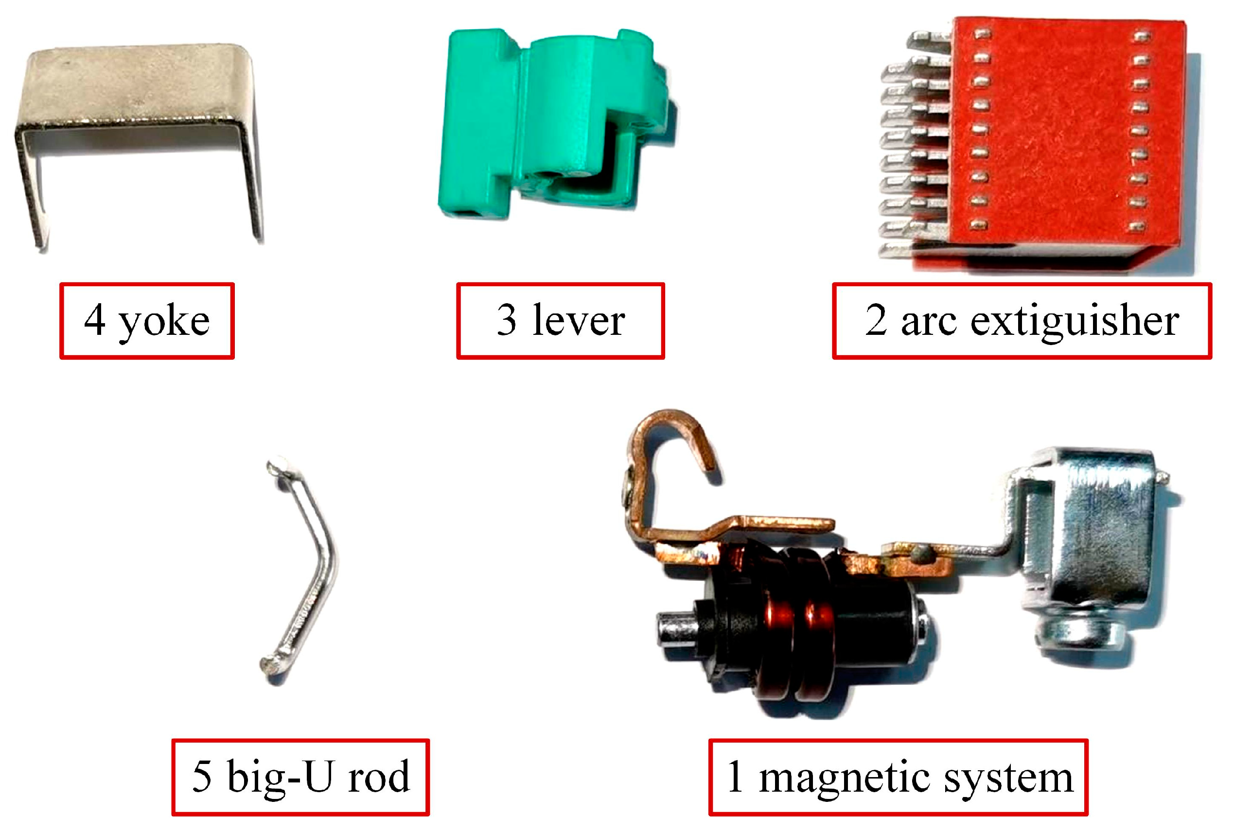
Miniature circuit breakers (MCBs) are low-voltage electrical protective apparatuses widely applied in low-voltage power distribution systems [1]. The production of MCBs is extremely large, i.e., more than a billion pieces per year in China. Therefore, there is a large demand for machinery with MCB automatic assembly. Meanwhile, an MCB series includes multiple models varied by the nominal current, and the shapes of the components with the same functionality of different models are varied. To reduce the cost and improve the efficiency for manufacturing, it is expected that all MCB models can be assembled by a single set of assembly devices and the switching between different models. The internal structure of an MCB is shown in Figure 1, and the components to be assembled are shown in Figure 2. Therefore, robotic assembly is studied to improve flexibility and efficiency [2,3]. We propose a flexible-assembly method that clamps multiple types of internal components and fixes them into the case via several industrial robots. In our case, components of different types are mixed and randomly placed on the loading carrier, so the position and posture adjustment for the components is the first stage of the assembly procedure [4].
It is important to note that there are two important terms for a component:
Position—the coordinate of the component center (or the representative point) in a 3D space.
Posture—the rotation angles of the component in a 3D space, compared with the standard template.
In our project, a robotic platform for posture adjustment is designed, as shown in Figure 3. A ROKAE XB4 six-axis robot [5] is employed to clamp each component by the corresponding gripper from the loading carrier, adjust it to the specific posture, and place it on the corresponding slot of the positioning carrier. Then, the positioning carrier can be transmitted to the next stage, and the components can be easily picked and fixed into the MCB case. In the adjustment stage, to precisely pick and adjust each component on the loading carrier with one of the specially designed grippers of the claw at the end of the robot (see Figure 4), vision guidance [6,7] that locates the positions and estimates the postures of the components is required.
Hence, we propose a novel stereo-vision-based method to assist the robot in adjusting the components. A 3D stereo camera is applied to acquire the field depth of the multi-type components randomly placed on the loading carrier, and the algorithm that recognizes the category, determines the location, and estimates the posture of every component is developed. The significance of our work is that the registration precision of both positions and postures is much higher than existing methods and can meet the requirements of the robotic flexible assembly. According to the component information given by the vision system, the robot can correctly select the gripper and precisely clamp every component at the predefined position, as well as adjust it to the proper posture.

2. Prior Work

In the assembly industry, there are two categories of visual approaches for spatial positioning and postural estimation varied by imaging schemes: 2D approaches, which obtain grayscale or RGB images from the field of view (FOV), and 3D approaches, which describe the FOV by its field depth to form stereo scenes. In most industrial applications, 2D approaches can successfully detect and locate objects. For example, for outdoor cases, Hoffmann [8] proposed a method that applied color information to form key-point detectors and descriptors and perform posture matching for outdoor objects. For indoor cases, Zhou et al. [9] developed an automatic inspection system that detected surface defects using five cameras from different directions, extracting candidate regions via multi-scale Hessian matrix fusion [10], and determining defect regions via a support vector machine. However, in our situation, 2D approaches are constrained by the limitation of 2D imaging, since the cameras cannot reliably capture the edge information of the components with thin structures, e.g., the edges of the yoke and the big-U rod, due to their shapes and reflective surfaces. Three-dimensional approaches can effectively obtain information about thin structures and are more robust in different lighting conditions. Therefore, a 3D method can be an optimal approach for MCB assembly.
Scholars have proposed multiple methods of recognition and positioning with 3D images. Birdal et al. [11] proposed a recognition method that cut the scene point cloud and matched it using point-to-point features. However, it could not be applied to an occluded scene or obtain precise recognition results. Wu et al. [12] proposed a 3D scene rebuild method based on Fast Point Feature Histogram (FPFH) and Iterative Closest Point (ICP). However, the precision could not meet the requirements of small-sized component assembly. Liu et al. [13] proposed a method that acquired the edge-description symbol of point-to-point features to match each other, but this method only selected part of the geometry features of the point cloud, which could not guarantee the recognition’s robustness. Yu et al. [14] developed a LiDAR point cloud registration algorithm that improved ICP by introducing ground segmentation and KD-tree-based pair filtering so that the accuracy, efficiency, and stability were improved. However, the selection of the initial points of ICP was not introduced, and the convergence could not be guaranteed. Different from ICP and its developments, Normal Distributions Transform (NDT) [15,16] is another widely used registration method that matches point clouds in segmented grids via the probability density function. Compared with ICP, it can achieve similar registration precision with lower computational complexity.
Multi-stage methods have been proposed to improve both efficiency and precision. Liu et al. [17] proposed a 3D registration method that selected the registration of interesting points from feature lines extracted based on super-voxels and introduced a “clustering, primary matching, and coarse registration” strategy to effectively reduce the calculation complexity of point cloud registration. Efraim et al. [18] employed a novel correlation operator between functions defined on sparsely and non-uniformly sampled point clouds. Correlation between point clouds was evaluated using a methodology that aggregated the inner product of feature vectors of key points. The method showed improvement when applied to challenging datasets.
Scholars have also proposed hybrid methods using both 2D and 3D images. Zhang et al. [19] constructed a 2D and 3D hybrid vision system for the guidance of a moveable robot used to assemble rocket fuel tanks. Cao et al. [20] presented a novel registration approach that combined a point cloud with RGB image information, which was significantly superior to classic matching methods. However, most of the time, integrating 2D and 3D cameras requires extra coordination and lighting calibration work. Meanwhile, the cost is raised.
In addition, commercial solutions for 3D point cloud registration are provided by device manufacturers, e.g., Photoneo, a well-known stereo camera manufacturer, has released a commercial SDK for object localization [21]. It can locate objects of different sizes and shapes efficiently and is widely utilized in a large number of industries.
However, applying stereo vision to the assembly of small-sized components, e.g., MCB assembly, is still challenging due to the high precision requirement. Meanwhile, the methods above only provide matching to objects of single-type components, while our case requires the registration of different components in a scene. For our case, none of the methods described above can meet the precision of assembly requirement, i.e., a maximum position error of 0.2 mm and a maximum posture error of 0.5°. Significant improvement from the existing methods is required to solve the spatial positioning and postural estimation problems. Hence, we propose a novel method developed from ICP and FPFH. The method we propose converts the 3D CAD model of each component to a surface point cloud model via voxel down-sampling as a matching template from which point cloud features are extracted. A rough matching and a fine registration between the templates and targets are sequentially performed to improve both efficiency and precision.

3. Scheme of the Proposed Method

3.1. Hardware of the Vision System

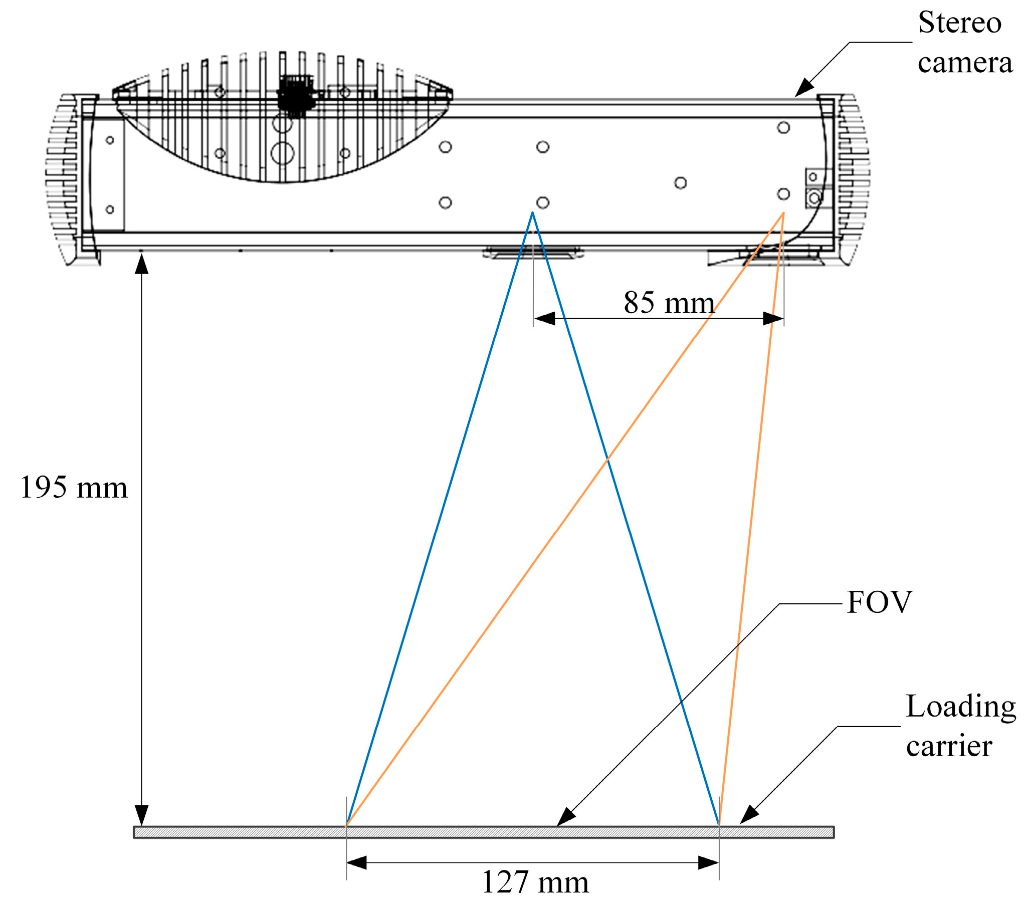
Considering that the minimal diameter of an MCB component is approximately 1 mm, the precision of the stereo camera must be higher than 0.1 mm. In addition, to scan all components in the camera’s field of view, the dimensions of the view field must be larger than 90 × 70 mm. Therefore, we employ a Phoxi 3D Scanner XS stereo camera [22] whose scanning precision is 0.055 mm, selected to meet the requirements. The specifications of the stereo camera are shown in Table 1.
The vision system is shown in Figure 5. The two yellow lines illustrates the range of the generated structured light, and the range beween the two blue lines represents the FOV of the camera lense.
The stereo camera collects the point clouds of the components on the loading carrier and sends the data to a computer. The heights of the components are between 1.5 and 15 mm, and the distance between the stereo camera and the upper surface of the loading carrier is 195 mm, so the object distances are within [180, 193.5], which is around the optimal scanning distance of the camera. The side length of the field of view (FOV) is 127 mm, which can contain all components of a single-pole MCB.
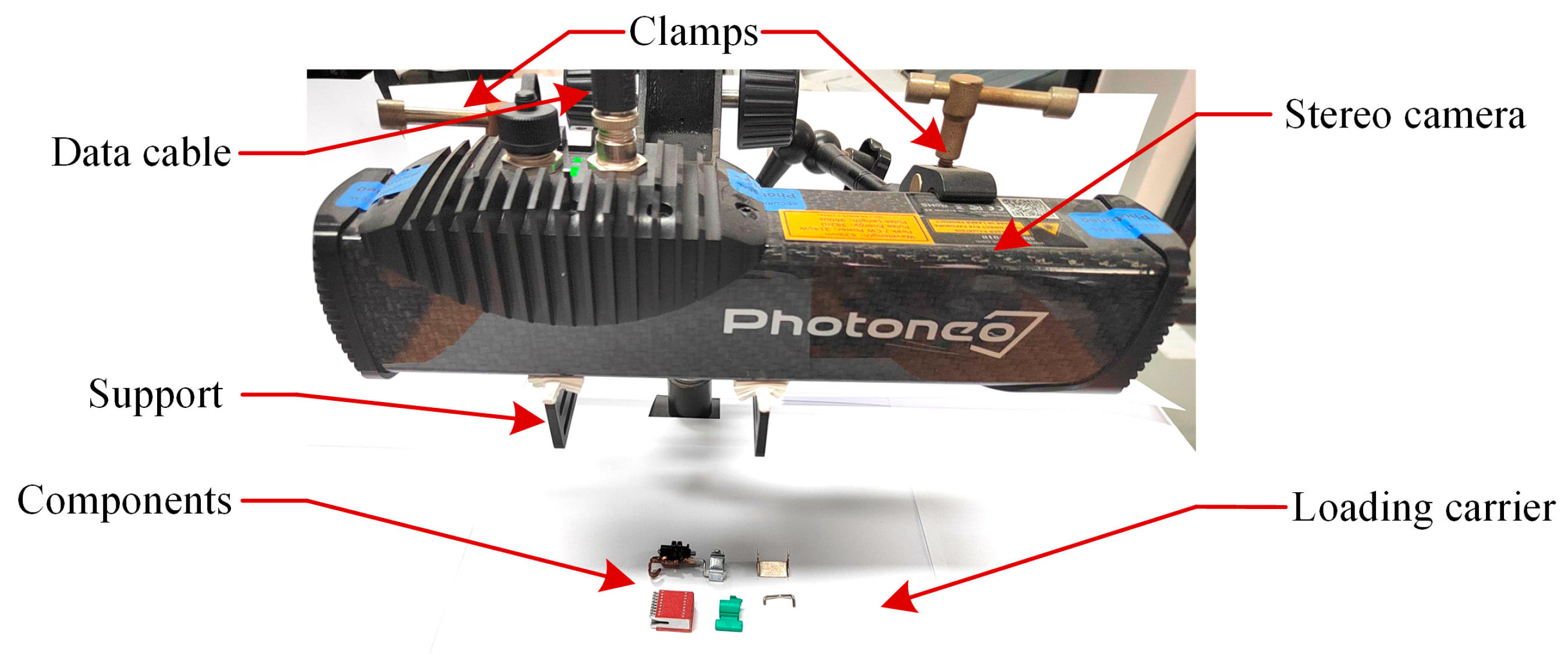
Figure 6 shows how the vision system is set up. The stereo camera is fastened on a frame by a support and two clamps. The parallelism between the camera and the loading carrier can be adjusted by the flexible support and clamps and verified by the imaging outputs of the camera so that the error of alignment can be minimized. A specified Ethernet cable is connected to a Power-over-Ethernet (PoE) adapter for both power supply and data transmission to the computer.

3.2. Overview of the Method

The components are small-sized, multiplex-shaped, and complex-structured, with blurred surfaces and edges. Fast, flexible assembly is a big challenge since it is very difficult to achieve the correct position and posture accurately via efficient 2D vision processing. Therefore, a 3D-vision-based method is proposed for spatial positioning and posture estimation of MCB components with a novel point cloud registration method. The procedure of the method is as follows (illustrated by Figure 7):
  • The computer-aided design (CAD) models of the components are sampled to obtain surface point clouds that contain richer feature information, which improves the precision of point cloud registration.
  • The scene point cloud is filtered, clustered, and segmented to obtain candidate-matching regions.
  • Point cloud features are extracted by Intrinsic Shape Signatures (ISSs) [23] from the templates and the candidate-matching regions are described by a Fast Point Feature Histogram (FPFH). Then, Sample Consensus Initial Alignment (SAC-IA) [24,25] is applied to achieve a rough matching.
  • Fine registration is used to improve the precision of the results obtained by rough matching. To perform a fast search, fine registration employs Iterative Closest Point (ICP) [23,26] with a K-dimensional Tree (KD-tree) [27] to obtain a set of point pairs of minimum Euclidian distances between the source and target point clouds. Meanwhile, Random Sample Consensus (RANSAC) [28] is employed to remove incorrectly matched point pairs to further raise the performance of the ICP algorithm.
  • Finally, the result is visualized by moving a design model to the registered position and posture.

4. Spatial Positioning and Postural Estimation Method

4.1. Preprocessing

The preprocessing includes two phases: 3D CAD model sampling and scene point cloud acquisition, filtering, clustering, and segmentation. Since the CAD models have a higher resolution than model point clouds, in order to achieve matching between point cloud pairs, the CAD models are down-sampled before matching. We convert the CAD models into model surface point clouds (MSPCs) by a sampling interval equal to the resolution of the stereo camera (0.055 mm). Figure 8 shows the surface point cloud obtained from the 3D CAD model. Compared with traditional point cloud approaches, the MSPC sampled from a design model contains richer information and more sufficient features, which improves the accuracy of point cloud matching. The type, position, and posture can be accurately matched in a scene with multiple randomly postured components.
A scene point cloud is the point cloud of the area to be matched. It is obtained by the 3D point cloud camera. The preprocessing of the scene point cloud can avoid global matching and improve the matching efficiency. Before matching, the scene point cloud is filtered, clustered, and segmented to obtain candidate-matching regions. In the subsequent matching process, only the candidate-matching regions are matched. Hence, the matching efficiency is greatly improved. The original scene point cloud is shown in Figure 9.
The original scene point cloud is down-sampled by voxel filtering, which simplifies the point cloud without the loss of shape features. In the original scene point cloud (OSPC) acquired by the camera, a large part of the point cloud is the background of the tray, which is not useful and leads to mismatches, as well as increases the calculation. SAC segmentation [24] combined with parameter tuning is used to remove the background plane of the point cloud. The point cloud after removing the background plane is shown in Figure 10.
The scene point cloud is clustered and segmented by the Euclidean distance. The upper and lower thresholds of the number of points in a point cloud cluster are determined according to the distribution of the number of points of the component. The point cloud clusters that are too large, too small, or too far from the center of clusters are further filtered out. Finally, point cloud clusters meeting the requirements are kept. The segmented and filtered point cloud subsets (termed “candidate point clouds”, CPC) are rendered in different colors to distinguish different point cloud regions, as shown in Figure 11. The colored regions are selected as the candidates for rough matching and fine registration of the following stages.

4.2. Rough-Matching Process

Before applying the surface point cloud of a component to the processed scene point cloud for rough matching, the candidate regions with point counts close to the surface point cloud are selected, while the regions with significant point counts are skipped to further improve the efficiency. The point cloud rough matching employs ISSs [23] to extract point cloud features, and the FPFH operator [24] describes the features. SAC-IA [25] is employed to roughly match the surface point cloud to the segmented point cloud. The reason why the methods above are applied is as follows: ISS is relatively efficient and robust for different shapes of objects, such as the MCB components. FPFH is fast and robust to noise, so it is suitable for our acquired point cloud. SAC-IA is also fast and widely used for rough matching. The procedure of rough matching was performed according to the following steps:
  • Select sampling points according to conditions: select n sampling points from the candidate point cloud, and meanwhile, to ensure the discrimination of the FPFH features of each sampling point, the distance between each sampling point should be greater than the set threshold.
  • Search the corresponding point pair set: according to the FPFH features of the sampled points, nearest-neighbor searching is used in the model surface point cloud to find the point pairs with the smallest difference between the FPFH features of the MSPC and the CPC, and RANSAC [28] is used to remove incorrectly matched point pairs to obtain optimized point pairs with a similar feature set.
  • Obtain the optimal transformation parameters: first, the MSPC is transformed according to the matched point pair set obtained in Step 2, and then the matching effect is evaluated by the sum function of the distances between the transformed MSPC and the CPC. The Huber function is used to compute the sum function of the distance error.
H u b e r = i = 1 n H ( l i )
H ( l i ) { 1 2 l i 2 , l i > m l 1 2 m l ( 2 l i m l ) , l i < m l
where ml is the preset threshold, and li is the distance error of the i-th corresponding point pair after the transformation. The optimal transformation is thus achieved for rough matching by finding the minimum error computed by Equation (2).
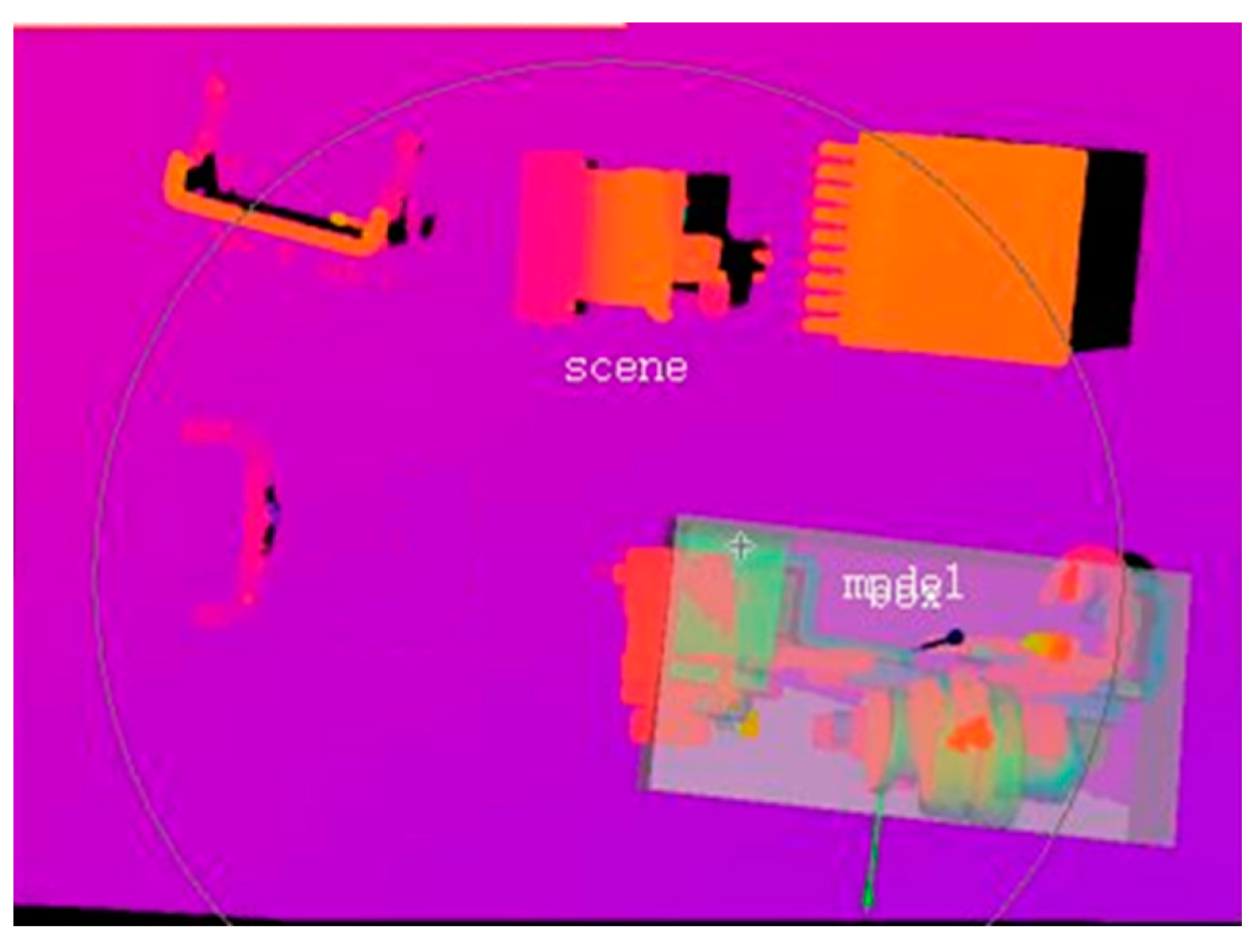
As shown in Figure 12, the original scene point cloud obtained by the 3D point cloud camera is color-rendered according to the field depth, which is used as a comparison before matching. Figure 13 shows the match result obtained by the rough matching of the magnetic system component. The results illustrate that the rough matching process achieves the approximate position and direction, but the error can still be observed. Therefore, fine registration is applied to improve the precision.

4.3. Fine Registration Process

The point cloud fine registration employs ICP [23] with a KD-tree [27], which obtains a set of point pairs of minimum Euclidian distances between the source and target point cloud. ICP requires a proper initial matching point to achieve high precision and convergency, as well as to reduce computational complexity. The rough matching results provide the initial matching points so the requirements can be met. The KD-tree provides an optimized mechanism that further accelerates the registration process.
Meanwhile, RANSAC is employed to remove the incorrect matching point pairs to further improve the performance of ICP. The proposed method can effectively resolve the local optimal problem that occurs in the classic ICP algorithm. Since the precision of classic ICP is influenced by the initial position, the rough matching result is applied as the initial position of the fine registration to improve the effect of the iterative optimization of ICP.
Assume the point set of the CPC is S = {s1, s2, s3, … sm}, where m is the point count of the CPC, and the transformed MSPC is G = {g1, g2, g3, … gn}, where n is the point count of the MSPC. The threshold of the mean squared error for each iteration is denoted by E. The threshold of the mean squared error difference between two adjacent iterations is represented by e. The maximum number of optimization iterations is kmax. The iterative optimization process of the fine registration is performed according to the following steps:
  • Obtain the optimized set of corresponding point pairs: each gi in G is searched within S to obtain a preliminary corresponding point pair set by finding the minimum Euclidean distance via the KD-tree search algorithm, and then the RANSAC algorithm is used to remove point pairs with large matching errors. Hence, the optimized corresponding point pair set {(si, gi)|i < n} is obtained.
  • Obtain the transform matrices R and T according to the point pair set obtained in Step 1: the transform matrices R and T are achieved by finding the minimum value of the target function f(R, T) as the optimization objective. The target function f(R, T) is as follows:
f ( R , T ) = 1 n i = 1 n g i ( R s i + T ) 2
3.
Update the MSPC by the transform matrices R and T obtained in Step (2): the MSPC update formula is as follows, where k is the number of iterations, Sk is the point cloud before the update, and Sk+1 is the point cloud after this update.
S k + 1 = R s k + T
4.
Calculate iteratively and judge the threshold: The mean squared errors dk and dk+1 after this iteration are calculated by Equations (5) and (6), and then the judgment of whether any of the threshold conditions (dk < E, dk+1dk < e, k ≥ kmax) are met is performed. If any conditions are met, the iteration stops; otherwise, go back to Step 1.
d k = 1 n i = 1 n g i k s i k
d k + 1 = 1 n i = 1 n g i k + 1 s i k + 1
5.
Perform point cloud registration after iterative optimization: the result of the last iteration is used as the optimal matching, and the optimal transform matrices R and T are obtained. Fine registration results are exhibited in Figure 14.
The MSPC is transformed by the matrices and registered to the CPC. Thus, the final registration is accomplished, as shown in Figure 14a, which is updated from the rough matching result shown in Figure 13. It can be observed that the matching precision between the MSPC and the SPC, including both the position and the posture, is significantly improved. The fine registration results for the other four components are shown in Figure 14b–e. To verify the effectiveness of the matching method, the fine registration results are obtained in different scenes.
The proposed method is almost parameter-free. The only parameter to be considered is the threshold of the coincidence degree, i.e., the percentage of the matched points. Taking the magnetic system component as an example, the relationships between the threshold of the coincidence degree and the errors of the position and posture are illustrated in Figure 15. It can be observed that the errors decrease with the increase in the threshold. On the other hand, the experiment proves that a higher threshold takes a longer processing time. When the threshold is 95%, it takes more than 1.5 s per process, which is still acceptable for our application. Hence, in the following, the threshold is set to 95% to achieve the highest precision.

5. Experiment and Analysis

5.1. Experiments and Evaluation

We establish a mechanism that evaluates the matching precision. The type, position, and posture of each component are computed, and they are compared with the ground truth. The posture is represented by the rotation angle. The component labels correspond to the labels in Figure 1. The ground-truth position (x, y, z) and posture (α, β, γ) of a component are achieved by measuring several points on the component surface using the robot exhibited in Figure 3, which uses its gripper to calibrate the appropriate gripping position and angle of the component due to its high precision (repeatability of ±0.02 mm) [5]. The camera scans the point cloud after the robot moves out of the field, and thus the matching results and the errors can be computed. We randomly placed the components on the loading carrier 20 times and performed spatial positioning and postural estimation each time.
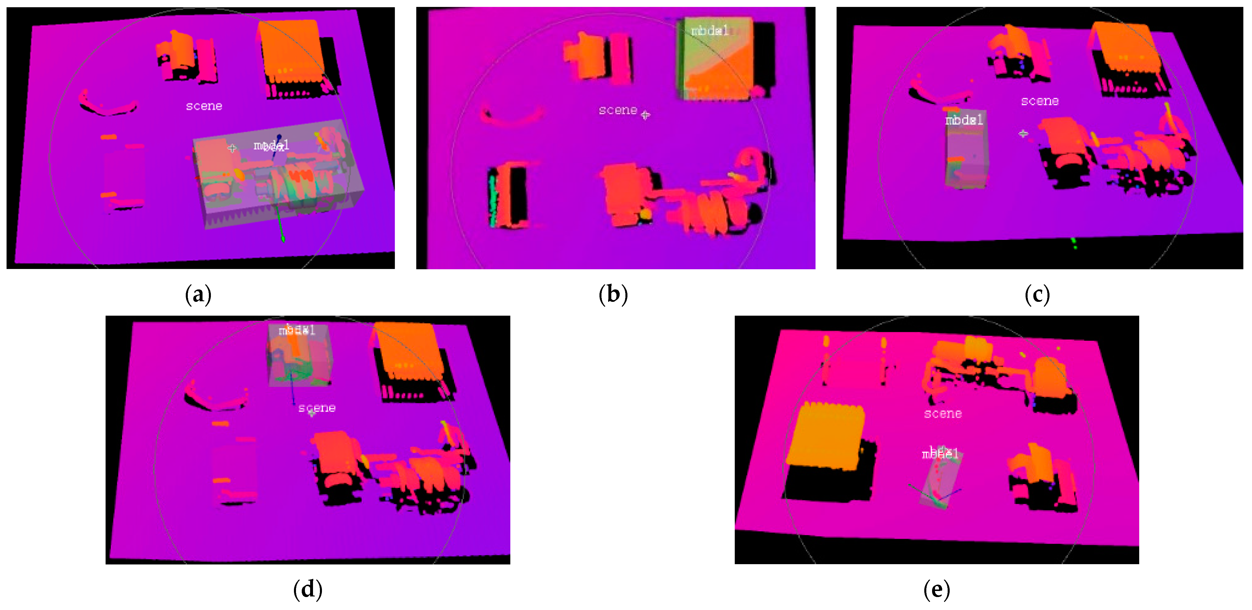
For comparison, we implemented the methods introduced in Chapter 2 and found that Normal Distributions Transform (NDT) [15] and the Photoneo localization method [21] could reach relatively high precisions. Hence, the two methods were selected for comparison. Figure 16 shows the results of the two methods. The differences between our method and the comparisons were not visually significant, so we also performed a numerical comparison in the following section.
We also compared the method proposed by this paper with our previously proposed 2D matching method, which used cascading convolutional neural networks (CNNs) for the classification of types, locations, and general postures; applied Oriented Fast and Rotated BRIEF (ORB) with Fast Approximate Nearest Neighbors [29] for feature matching; and employed RANSAC for error removal. We applied a high-resolution RGB camera of 2590 × 1942, i.e., 0.049 mm per pixel with the FOV in Figure 5, expecting precise matching. Finally, we obtained the spatial and postural matching shown in Figure 17.

5.2. Results and Analysis

In the experiment, the proposed method can correctly recognize the types of all components every time, i.e., the categorization accuracy is 100%. Table 2 exhibits the matching result of one of our test scenes. In Table 2, the maximum matching errors of different components are presented. It is indicated that the maximum error of the posture is (0.42, 0.41, 0.43)°, and the maximum position error is (0.17, 0.16, 0.15) mm (as shown in Table 3), which proves the high precision of the proposed method.
To verify the effectiveness of the proposed method, ten different scenes with all components randomly placed were tested. The matching errors of multiple repetitive tests of the proposed method, the NDT, the Photoneo localization method, as well as our 2D method, are shown in Table 3. In addition, since there is no field depth achieved by the 2D method, we measured its errors only in the 2D position (x, y) and posture α domains. The results indicate that Photoneo localization achieves higher precision than NDT, and our 2D method obtains higher precision than NDT and Photoneo localization. Our 3D method achieves the highest precision, of which the absolute matching errors are lower than 0.2 mm and 0.5°, significantly superior to the other three methods.
We also computed the processing time of all methods to verify whether they can meet the efficiency requirement. The proposed 3D method takes 1.43 s to process a scene on average, and there is an additional time of approximately 2 s for the scene point cloud acquisition by the stereo camera. The total time is longer than the NDT and the 2D method with the same processing computer. However, since the operation performed on a set of components by the robotic assembly system takes more than 20 s, the additional processing time has no influence on the performance and efficiency of the entire assembly operation.

6. Conclusions

This paper proposes a position- and posture-matching method for MCB components using field depth images acquired by 3D stereo cameras. Design models are converted into model surface point clouds (MSPCs) to match sense point clouds, and a two-stage strategy with rough matching and fine registration is used to achieve high precision. Compared with other methods, there is a significant improvement in using the proposed method.
The significance and innovativeness of our method lie in its ability to address the multiplexity and randomness of components, which is a challenge in flexible MCB assembly and has not been considered by previous research. In addition, our method achieves a balance between precision and efficiency, which shows its high practicality for industrial applications.
In future studies, improvements in registration precision and efficiency will be studied. Meanwhile, we aim to integrate the 3D vision system into our robotic platform. A flexible assembly system with industrial robots guided by the proposed vision method will be constructed, and the flexible MCB assembly will be accomplished. The system is scheduled to be applied in the manufacturing workshops of our cooperating companies shortly.

Author Contributions

Conceptualization, Z.W. and J.W.; methodology, Z.W. and J.Y.; software, J.Y.; validation, Z.W.; formal analysis, J.W.; investigation, Z.W. and H.X.; resources, Z.B.; data curation, Z.B. and H.X.; writing—original draft, Z.W. and J.Y.; writing—review and editing, J.W.; visualization, Z.W.; supervision, J.W.; project administration, Z.B.; funding acquisition, Z.B. All authors have read and agreed to the published version of the manuscript.

Funding

This research was funded in part by the National Natural Science Foundation of China, grant number 51975418; in part by the Department of Science and Technology of Zhejiang Province, grant number 2021C01046; and in part by the Department of Education of Zhejiang Province, grant number Y202044245.

Institutional Review Board Statement

Not applicable.

Informed Consent Statement

Not applicable.

Data Availability Statement

Not applicable.

Acknowledgments

We would like to thank the National Natural Science Foundation of China, the Department of Science Technology of Zhejiang Province, and the Department of Education of Zhejiang Province, who provided funds for this research. We also would like to thank Guichu Wu, chairman of the board at Zhejiang Juchuang Smartech Co., Ltd.

Conflicts of Interest

The authors declare no conflict of interest.

References

  1. Sun, S.; Wen, Z.; Du, T.; Wang, J.; Tang, Y.; Gao, H. Remaining Life Prediction of Conventional Low-Voltage Circuit Breaker Contact System Based on Effective Vibration Signal Segment Detection and MCCAE-LSTM. IEEE Sens. J. 2021, 21, 21862–21871. [Google Scholar] [CrossRef]
  2. Shi, X.; Zhang, F.; Qu, X.; Liu, B. An online real-time path compensation system for industrial robots based on laser tracker. Int. J. Adv. Robot. Syst. 2016, 13, 1729881416663366. [Google Scholar] [CrossRef] [Green Version]
  3. He, M.; Wu, X.; Shao, G.; Wen, Y.; Liu, T. A Semiparametric Model-Based Friction Compensation Method for Multi-Joint Industrial Robot. J. Dyn. Syst. Meas. Control 2021, 144, 034501. [Google Scholar] [CrossRef]
  4. Han, Y.; Shu, L.; Wu, Z.; Chen, X.; Zhang, G.; Cai, Z. Research of Flexible Assembly of Miniature Circuit Breakers Based on Robot Trajectory Optimization. Algorithms 2022, 15, 269. [Google Scholar] [CrossRef]
  5. XB4_ROKAE Robotics. Leading Robots Expert in Industrial, Commercial Scenarios. Available online: http://www.rokae.com/en/product/show/240/XB4.html (accessed on 8 June 2023).
  6. Suresh, V.; Liu, W.; Zheng, M.; Li, B. High-resolution structured light 3D vision for fine-scale characterization to assist robotic assembly. In Proceedings of the Dimensional Optical Metrology and Inspection for Practical Applications X, Online. 12 April 2021; p. 1. [Google Scholar]
  7. Erdős, G.; Horváth, D.; Horváth, G. Visual servo guided cyber-physical robotic assembly cell. IFAC-PapersOnLine 2021, 54, 595–600. [Google Scholar] [CrossRef]
  8. Hoffmann, A. On the Benefits of Color Information for Feature Matching in Outdoor Environments. Robotics 2020, 9, 85. [Google Scholar] [CrossRef]
  9. Zhou, Q.; Chen, R.; Bin, H.; Liu, C.; Yu, J.; Yu, X. An Automatic Surface Defect Inspection System for Automobiles Using Machine Vision Methods. Sensors 2019, 19, 644. [Google Scholar] [CrossRef] [PubMed] [Green Version]
  10. Lorenz, C.; Carlsen, I.-C.; Buzug, T.M.; Fassnacht, C.; Weese, J. A Multi-Scale Line Filter with Automatic Scale Selection Based on the Hessian Matrix for Medical Image Segmentation. In Scale-Space Theory in Computer Vision; Haar Romeny, B., Florack, L., Koenderink, J., Viergever, M., Eds.; Springer: Berlin/Heidelberg, Germany, 1997; Volume 1252, pp. 152–163. ISBN 978-3-540-63167-5. [Google Scholar]
  11. Birdal, T.; Ilic, S. Point Pair Features Based Object Detection and Pose Estimation Revisited. In Proceedings of the 2015 International Conference on 3D Vision, Lyon, France, 19–22 October 2015; pp. 527–535. [Google Scholar]
  12. Wu, P.; Li, W.; Yan, M. 3D scene reconstruction based on improved ICP algorithm. Microprocess. Microsyst. 2020, 75, 103064. [Google Scholar] [CrossRef]
  13. Liu, D.; Arai, S.; Miao, J.; Kinugawa, J.; Wang, Z.; Kosuge, K. Point Pair Feature-Based Pose Estimation with Multiple Edge Appearance Models (PPF-MEAM) for Robotic Bin Picking. Sensors 2018, 18, 2719. [Google Scholar] [CrossRef] [PubMed] [Green Version]
  14. Yu, J.; Yu, C.; Lin, C.; Wei, F. Improved Iterative Closest Point (ICP) Point Cloud Registration Algorithm based on Matching Point Pair Quadratic Filtering. In Proceedings of the 2021 International Conference on Computer, Internet of Things and Control Engineering (CITCE), Guangzhou, China, 12–14 November 2021; pp. 1–5. [Google Scholar]
  15. Biber, P. The Normal Distributions Transform: A New Approach to Laser Scan Matching. In Proceedings of the 2003 IEEE/RSJ International Conference on Intelligent Robots and Systems (IROS 2003) (Cat. No.03CH37453), Las Vegas, NV, USA, 27–31 October 2003. [Google Scholar]
  16. Zhang, R.; Zhang, Y.; Fu, D.; Liu, K. Scan Denoising and Normal Distribution Transform for Accurate Radar Odometry and Positioning. IEEE Robot. Autom. Lett. 2023, 8, 1199–1206. [Google Scholar] [CrossRef]
  17. Liu, L.; Xiao, J.; Wang, Y.; Lu, Z.; Wang, Y. A Novel Rock-Mass Point Cloud Registration Method Based on Feature Line Extraction and Feature Point Matching. IEEE Trans. Geosci. Remote Sens. 2022, 60, 21497545. [Google Scholar] [CrossRef]
  18. Efraim, A.; Francos, J.M. 3D Matched Manifold Detection for Optimizing Point Cloud Registration. In Proceedings of the 2022 International Conference on Electrical, Computer, Communications and Mechatronics Engineering (ICECCME), Malé, Maldives, 16–18 November 2022; pp. 1–5. [Google Scholar]
  19. Zhang, X.; Wang, Z.; Yu, H.; Liu, M.; Xing, B. Research on Visual Inspection Technology in Automatic Assembly for Manhole Cover of Rocket Fuel Tank. In Proceedings of the 2022 4th International Conference on Advances in Computer Technology, Information Science and Communications (CTISC), Virtual. 22–24 April 2022; pp. 1–5. [Google Scholar]
  20. Cao, H.; Chen, D.; Zheng, Z.; Zhang, Y.; Zhou, H.; Ju, J. Fast Point Cloud Registration Method with Incorporation of RGB Image Information. Appl. Sci. 2023, 13, 5161. [Google Scholar] [CrossRef]
  21. Photoneo Localization. SDK 1.3 Instruction Manual and Installation Instructions. Available online: https://www.photoneo.com/downloads/localization-sdk/ (accessed on 8 June 2023).
  22. 3D Scanner for Scanning Small Objects|PhoXi XS. Available online: https://www.photoneo.com/products/phoxi-scan-xs/ (accessed on 8 June 2023).
  23. Senin, N.; Colosimo, B.M.; Pacella, M. Point set augmentation through fitting for enhanced ICP registration of point clouds in multisensor coordinate metrology. Robot. Comput. Integr. Manuf. 2013, 29, 39–52. [Google Scholar] [CrossRef]
  24. Rusu, R.B.; Blodow, N.; Beetz, M. Fast Point Feature Histograms (FPFH) for 3D registration. In Proceedings of the 2009 IEEE International Conference on Robotics and Automation, Kobe, Japan, 12–17 May 2009; pp. 3212–3217. [Google Scholar]
  25. Rusu, R.B.; Blodow, N.; Marton, Z.C.; Beetz, M. Aligning point cloud views using persistent feature histograms. In Proceedings of the 2008 IEEE/RSJ International Conference on Intelligent Robots and Systems, Nice, France, 22–26 September 2008; pp. 3384–3391. [Google Scholar]
  26. Besl, P.J. A method for registration of 3d shapes. IEEE Trans. Pattern Anal. Mach. Intell. 1992, 14, 239–256. [Google Scholar] [CrossRef] [Green Version]
  27. Kalpitha, N.; Murali, S. Object Classification using SVM and KD-Tree. Int. J. Recent Technol. Eng. 2020, 8. [Google Scholar] [CrossRef]
  28. Fischler, M.A.; Bolles, R.C. Random Sample Consensus: A Paradigm for Model Fitting with Applications to Image Analysis and Automated Cartography. In Readings in Computer Vision; Fischler, M.A., Firschein, O., Eds.; Morgan Kaufmann: San Francisco CA, USA, 1987; pp. 726–740. [Google Scholar]
  29. Muja, M.; Lowe, D.G. Fast Approximate Nearest Neighbors with Automatic Algorithm Configuration. In Proceedings of the International Conference on Computer Vision Theory and Applications, Lisboa, Portugal, 5–8 February 2009. [Google Scholar]
Figure 1. Internal structure of an MCB.
Applsci 13 08432 g001
Figure 2. Components of an MCB.
Applsci 13 08432 g002
Figure 3. Robotic platform for posture adjustment.
Applsci 13 08432 g003
Figure 4. Multi-gripper claw.
Applsci 13 08432 g004
Figure 5. Hardware design of the stereo vision system.
Applsci 13 08432 g005
Figure 6. Stereo vision system.
Applsci 13 08432 g006
Figure 7. Flowchart of the process.
Applsci 13 08432 g007
Figure 8. Down-sampling for the magnetic system component: (a) 3D design model; (b) sampled surface point cloud.
Applsci 13 08432 g008
Figure 9. Original scene point cloud.
Applsci 13 08432 g009
Figure 10. Point cloud after removing background.
Applsci 13 08432 g010
Figure 11. Color rendering of cluster segmentation results.
Applsci 13 08432 g011
Figure 12. Original scene point cloud rendered by colors.
Applsci 13 08432 g012
Figure 13. Rough matching result.
Applsci 13 08432 g013
Figure 14. Fine registration results of all components. (a) Magnetic system. (b) Arc extinguisher. (c) Yoke. (d) Lever. (e) Big-U rod.
Applsci 13 08432 g014
Figure 15. Relationships between the threshold of the coincidence degree and the errors of the magnetic system component.
Applsci 13 08432 g015
Figure 16. Matching results with NDT (upper column) and Photoneo method (lower column). (a) Magnetic system. (b) Arc extinguisher. (c) Yoke. (d) Lever. (e) Big-U rod.
Applsci 13 08432 g016
Figure 17. The test results proved that compared with several existing 2D methods, our 2D matching method achieved the highest precision in this circumstance. (a) Magnetic system. (b) Arc extinguisher. (c) Yoke. (d) Lever. (e) Big-U rod.
Applsci 13 08432 g017
Table 1. Specification of the stereo camera.
ParameterValue
BrandPhotoneo
ModelPhoXi 3D Scanner XS
Imaging methodStructured light
Point-to-point distance (sweet spot)0.055 mm
Scanning range161–205 mm
Optimal scanning distance (sweet spot)181 mm
Scanning area (sweet spot)118 × 78 mm
3D points throughput16 Million points per second
GPUNVIDIA Pascal Architecture with 256 CUDA cores
Table 2. Recognition result of positions and postures using the proposed method.
Component LabelPosture (α, β, γ) (°)Position (x, y, z) (mm)
Ground TruthResultErrorGround TruthResultError
11.23, 2.73, 40.580.82, 2.34, 40.150.41, 0.39, 0.43−15.21, 18.34, 192.3−15.08, 18.20, 192.4−0.13, 0.14, −0.10
288.45, −3.76, 13.6188.03, −4.02, 13.850.42, 0.26, −0.2420.55, 30.72, 186.0520.63, 30.56, 185.94−0.08, 0.16, 0.11
364.70, 307.19, 67.2564.98, 306.78, 67.6−0.28, 0.41, −0.35−9.34, −2.20, 187.53−9.47, −2.05, 187.380.13, −0.15, 0.15
492.56, 42.68, 25.7792.93, 42.34, 25.51−0.37, 0.34, 0.26−25.50, −4.97, 187.62−25.61, −4.89, 187.730.11, −0.08, −0.11
522.40, 56.52, 7.8322.17, 56.66, 7.670.23, −0.14, 0.1615.06, −6.43, 193.5714.89, −6.57, 193.440.17, 0.14, 0.13
Table 3. Matching error comparison of different methods.
Component LabelMAE of Postures (°)MAE of Positions (mm)
NDTPhotoneo2DProposedNDTPhotoneo2DProposed
12.791.220.470.483.261.530.280.20
22.541.090.370.321.881.100.340.13
32.221.410.410.452.861.150.330.16
43.631.140.400.392.110.720.250.17
54.031.850.440.331.941.350.280.14
Average3.141.450.420.382.311.290.300.15
Disclaimer/Publisher’s Note: The statements, opinions and data contained in all publications are solely those of the individual author(s) and contributor(s) and not of MDPI and/or the editor(s). MDPI and/or the editor(s) disclaim responsibility for any injury to people or property resulting from any ideas, methods, instructions or products referred to in the content.