Article

A Fast Acquisition Algorithm for Hybrid Signals of 5G and BeiDou B1

1
School of Electronic & Information Engineering, Beihang University, Beijing 100080, China
2
Hefei Innovation Research Institute of Beihang University, Hefei 230012, China
*
Author to whom correspondence should be addressed.
Appl. Sci. 2023, 13(13), 7818; https://doi.org/10.3390/app13137818
Submission received: 18 May 2023 / Revised: 27 June 2023 / Accepted: 30 June 2023 / Published: 3 July 2023
(This article belongs to the Special Issue Advanced GNSS-5G Hybrid Positioning Technologies and Applications)

Abstract

:
With the large-scale use of BeiDou navigation and 5G technology worldwide, integrating BeiDou navigation and communication has become a hot research topic in navigation and positioning technology. Low-cost, miniaturized, and susceptible mixed-signal receivers will become the future receiver technology development trend. However, the current receiver technology still faces the challenge of further improving the positioning service capability and communication quality, which includes the lack of practical analysis of the compatibility between signals and the lack of mixed-signal processing capability of the receiver baseband key technology. To address these problems, we start by analyzing the signal part of 5G out-of-band signals falling into the BD B1 signal band, conduct a detailed analysis of the mixed signal regime and frequency planning, and design a hybrid receiver architecture compatible with both signals, and propose an SC-PMF-FFT fast capture algorithm based on strong correlation, which takes advantage of the strong correlation of signals broadcast on the BD B1 frequency point from B1I to B1C, and reuses the structure of the CDMA system signal capture algorithm to complete the fast capture of 5G signals using an OFDM system. The experiments show that the method can capture the BeiDou B1 signal with a sensitivity of −154 dBm and a whole constellation capture time of no more than 40 ms with the inlet power of the 5G signal not exceeding −45 dBw.

1. Introduction

BeiDou is a satellite navigation system developed by China, which has the functions of navigation and positioning, short message communication, and can provide high-precision positioning, timing, and speed measurement services, and has played an important role in rail transportation, industrial digitalization, and precision agriculture. The fifth-generation communication technology can provide higher speed, lower latency, and more reliable mobile communication services, significantly expanding mobile internet application scenarios. BeiDou navigation and 5G services are increasingly important in human society. However, the signal frequency of BeiDou navigation and positioning services is located in the L-band, which is very close to some frequency bands of FR1 of 5G. Due to the high power of 5G signals emitted by ground base stations and the low power of BeiDou signals on the ground, this leads to significant interference in the reception link of BeiDou signals. Therefore, the problem of compatible reception of BeiDou navigation and 5G signals has attracted more and more attention from the academic community.
The following research focuses on the key issues affecting the performance of GNSS and 5G signals regarding positioning, timing, and accuracy on hybrid architectures and platforms. The following research focuses on GNSS and 5G signals in terms of hybrid positioning, compatibility, and interference detection. Peral-Rosado et al. present preliminary experimental results of hybrid positioning tests with 5G and GNSS and evaluate the achievable positioning performance of GNSS and 5G. The paper examines the possible gains in complete performance by fusing real GNSS and simulated 5G observations. It shows the importance of GNSS and 5G fusion in harsh environments [1]. Fabius et al. propose that the technology of 5G communication-assisted GNSS can broadcast ephemeris and corrections from newly implemented IoT base stations to user terminals and also send secure positioning information from terminals to monitor network applications, improving the performance of IoT in terms of accuracy, continuity, and time to first fix (TTFF) [2]. Tong et al. proposed a robust adaptive fading filter (RAF) algorithm based on predicted residuals and a joint Kalman filter (FKF) algorithm operating in fused feedback mode in the context of a 5G network environment based on device-to-device (D2D) and self-organizing network (SON) technologies to achieve robust, reliable, and continuous high-precision positioning services with anti-interference capability and good generality after integrating BDS and SON positioning data [3]. Wang et al. investigated location-based TA estimation for 5G-integrated LEO satellite communication systems. The proposed method can approach the restricted Cramer–Rao lower bound (CRLB) for TA estimation, thus ensuring uplink frame alignment for different users [4]. Wang et al. analyzed the mutual interference problem between the radio-determined satellite service (RDSS) of BeiDou and 5G signals due to the similar operating frequencies and derived the exact range of neighboring frequency effects to improve the electromagnetic protection of RDSS receivers [4]. Famili et al. detected GPS spoofing attacks by GPS signals and 5G radio positioning signals and used 5G positioning instead of GPS positioning to avoid GPS spoofing attacks. The experimental results showed that the detection rate exceeded 98% [5]. Zhang et al. proposed an integrated GNSS/5G 3D localization scheme based on D2D communication, which improved the localization accuracy by about 58% over the GNSS localization results using time of arrival (TOA) and received signal strength (RSS) measurements in a 5G network using density space clustering with noise (DBSCAN) and particle filtering (PF) algorithms [6]. Klus et al. proposed a solution in the context of 5G and machine learning to improve the positioning accuracy in urban areas by obtaining the location of user equipment (UE) from beamforming radio signal strength (RSS) measurements and fusing them with GNSS-based positioning data to improve the overall positioning performance [7].
The following research focuses on the key issues affecting the performance of GNSS and 5G signals regarding positioning, timing, and accuracy on hybrid architectures and platforms. Guidotti et al. discuss the architecture and key technologies of a 5G system based on a satellite platform, evaluate the impact of satellite channel characteristics on the physical and media access control layers, and propose different solutions based on the services and architectures considered [8]. Qi et al. proposed a simplified 5G/GNSS fused positioning system architecture using only a 5G base station and observations from a GNSS satellite. The improvement of fused positioning over pure 5G positioning is more than 32%, independent of the time synchronization error between the 5G base station and the GNSS satellite [9]. Chaloupka et al. keep the time alignment error in 5G base station transmit ports required for coordinated multipoint technology below 65 ns by evaluating mass-market GNSS receivers’ relative time (phase) synchronization [10]. Jin et al. proposed a 5G coding and carrier phase receiver incorporating a round-trip time (RTT) ranging method and an integrated 5G/GNSS positioning architecture. Experimental results showed that the integrated 5G/GNSS positioning improved the standalone GNSS solution’s accuracy and availability. The proposed 5G RTT ranging method showed a maximum root mean square error (RMSE) of 1.109 m [11]. Shamaei et al. developed a navigation method using 5G signals, which utilizes the downlink channel and proposes a structure that can generate 5G reference signals using software radio (SDR). The experimental results show that the standard deviation of the ranging error between SDR and accurate 5G signals is 1.19 m [12]. Li et al. proposed a combined BDS and 5G PPP observation model for the problem of the long convergence time of receivers in urban areas with severe satellite occlusion. The experimental results show that this technique can effectively accelerate convergence while improving positioning accuracy [13]. Bai et al. proposed a multi-rate adaptive Kalman filter (MRAKF) for GNSS-5G hybrid positioning with a hybrid sequence fusion scheme, which can effectively solve the problems of considerable measurement noise uncertainty and degradation of positioning accuracy and system convergence in GNSS-5G hybrid systems due to the near–far effect of 5G base stations [14]. Pan et al. proposed an algorithm to eliminate neighborhood differences and improve the time synchronization accuracy between 5G base stations. This effectively solved the problem of significant time synchronization errors caused by different visual satellite groups. The accuracy of time synchronization between 5G base stations is improved [15]. Destino et al. conducted a study by deriving the Fisher information matrix (FIM) and subsequent lower bounds for position, rotation, and clock-offset errors for the 5G-GNSS combined positioning system, demonstrating that the 5G-GNSS combined positioning technique has significant advantages in terms of positioning accuracy, coverage, rotation estimation, and clock error estimation [16]. Lukcin et al. proposed a simulation environment based on a ray-tracing (RT) channel model simulating global navigation satellite system (GNSS) signals, which was validated and extended to simulate 5G PRS and detection reference signals (SRS). The simulated 5G signals improved GNSS positioning accuracy with hybrid positioning methods, especially in complex channel conditions, such as typical industrial environments [17]. Del Peral-Rosado et al. propose the use of hybrid GNSS, 5G, and sensor algorithms to provide accurate three-dimensional (3D) location and motion information, especially for challenging urban and suburban scenarios; analyze existing localization techniques, including signals, localization methods, algorithms, and architectures; and discuss design considerations for 5G overlay networks through simulation results on 5G signal bandwidth, antenna arrays, and network deployment [18]. Li et al. developed a positioning algorithm combining BDS and 5G technologies. The experimental results show that introducing 5G base stations can effectively improve the positioning accuracy and the reliability of positioning results under different occlusion conditions. Increasing the number of 5G base stations or optimizing the geometric configuration can further improve the accuracy and reliability of the fused positioning technique. The more severe the satellite occlusion environments, the better the improvement is with introducing 5G base stations [19]. Li et al. proposed a combined RTK/fifth generation (5G) mobile communication technology positioning model to improve positioning accuracy under medium and long baselines. In particular, the RTK/5G model can also achieve good positioning results in some cases where satellites are obscured. The combined RTK/5G positioning model is essential for achieving high-accuracy, real-time, and continuous positioning in complex environments [20].
The following study focuses on the specific structure and algorithms of 5G/GNSS hybrid reception and compares the algorithms’ performance. Zhao et al. proposed a 5G millimeter-wave-based radar-assisted localization method. The experimental results showed that the proposed radar detection method was well suited for UAV detection and identification, providing an effective GPS-independent method for UAV tracking [21]. Alghisi et al. simulated digital surface models (DSMs) associated with different urban scenarios, calculating and analyzing the time series of the number of GNSS satellites in the field of view, their geometry, and the derived quality indices. They analyzed different geometric configurations of 5G base stations simulated around the observer in an urban canyon. The results showed a significant improvement in the localization performance in different urban scenarios [22]. Shang et al. point out that due to the high power of the 5G base station, it can become an interferer for vulnerable BeiDou B1I receivers. This adverse effect can be offset by reducing the interfering signal ratio (ISR), increasing the integration time, or increasing the accumulation time [23]. Jia et al. proposed a Kalman-filter-based receiver autonomous integrity monitoring (RAIM) algorithm to ensure safe vehicle navigation in urban environments using sequential measurements from GNSS and 5G [24]. Peral-Rosado et al. proposed a new scenario definition and a generic and representative 5G and GNSS observation data model for simulation experiments using 5G centimeter-wave (cmWave) and millimeter-wave (mmWave) transmissions for high-accuracy positioning to complement the availability of GNSS in harsh environments such as urban canyons. The results show that positioning accuracy can reach a sub-meter level in harsh environments [25]. Mata et al. point out that for high-precision positionings, such as supporting autonomous driving or industrial automation, the integration of GNSS (augmented by precision or differential corrections), ground-based technologies, and complementary sensors will play a key role in 5G positioning [26].
As shown in Figure 1, we first analyze the compatibility of BeiDou navigation and 5G signals, summarize the 5G band range of the proximity of BeiDou signals, and discuss the NR spectrum characteristics and radiation characteristics of 5G signals to conclude the reception feasibility of these two hybrid signals. Then, we propose a hybrid signal acquisition algorithm for BeiDou signals and 5G signals which takes advantage of the signal regime proximity and signal frequency proximity of BeiDou and 5G signals, and provide a detailed analysis of the performance improvement of the algorithm at the levels of signal capture accuracy, capture sensitivity, capture time, and capture probability. Finally, we conduct hybrid signal receiver performance testing and verification, introduce the basic hardware and software architecture of the hybrid signal receiver, build a test environment to conduct practical testing of the acquisition algorithm, and verify the experimental effect of the algorithm.
In brief, the main contributions of our proposed method are as follows:
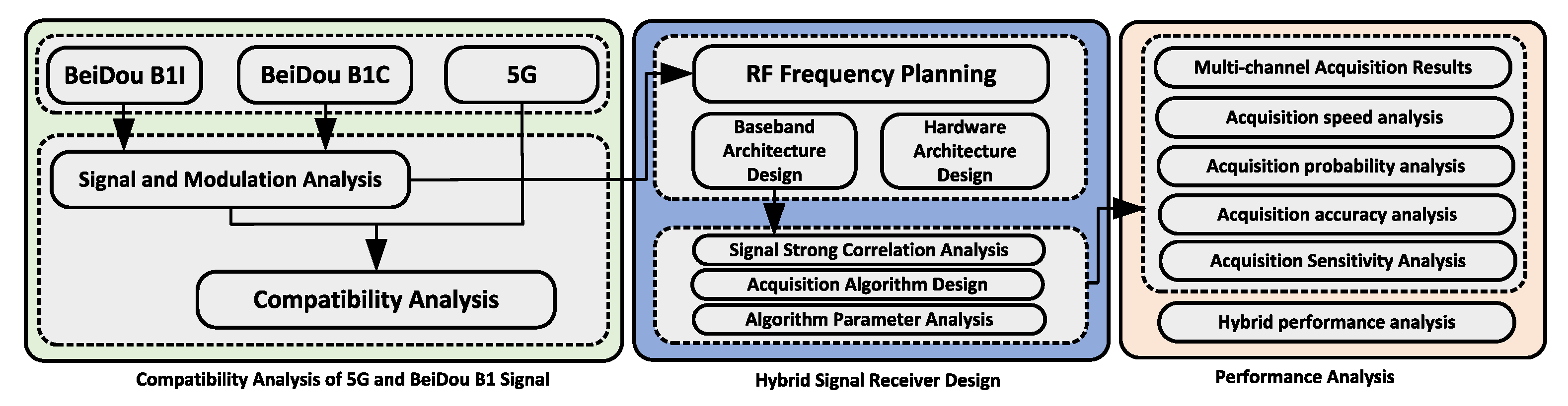
  • We analyze the BeiDou and 5G system signals, summarize the 5G frequency bands close to the BeiDou signals, and discuss the NR spectrum characteristics and radiation characteristics of 5G. Finally, the current ITU protection standard for navigation signals is analyzed.
  • We provide a detailed analysis of the mixed-signal regime and frequency planning and design a hybrid receiver architecture compatible with both signals, and hardware design for the RF front-end circuit, clock circuit, baseband circuit, and interface circuit.
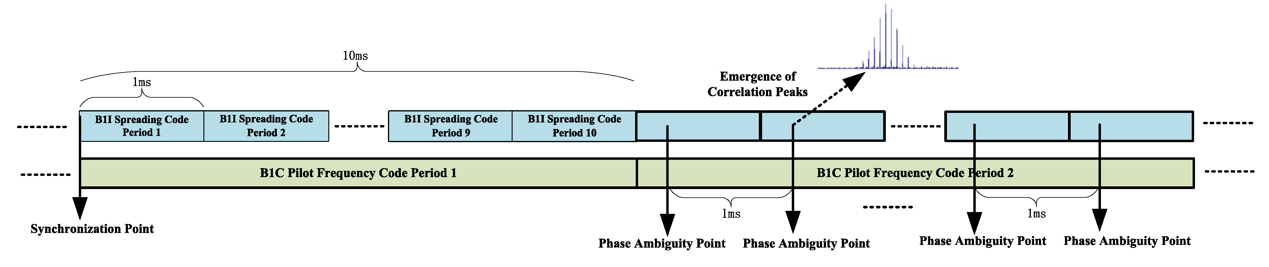
  • We propose a strong-correlation-based SC-PMF-FFT fast capture algorithm, which utilizes the strong correlation of signal broadcast on the B1 frequency point of BeiDou, performs fast decoding phase ambiguity processing for the strongly correlated signals from B1I to B1C, and reuses the structure of the CDMA system signal capture algorithm to complete the fast capture of 5G signals using an OFDM system.

2. Proposed Method

2.1. Compatibility Analysis of 5G and BeiDou B1 Signal

2.1.1. BeiDou B1 Signal System

The BeiDou system provides various services, including RNSS services provided by L-band signals, satellite-based augmentation, ground-based augmentation, global short message communication, and regional short message communication provided by S-band. The frequency distribution of BeiDou signals is the same as that of other satellite navigation systems such as global positioning system (GPS) and Galileo. The signals in the L-band of BeiDou include three frequency points B1, B2, and B3. Officials have further developed the classification into B1I, B1C, B2a, B2b, and B3I based on specific types of services. A summary of the primary modulation mode, pseudorandom noise (PRN) code, channel coding, messages, and other parameters of the BeiDou satellite L-band signals is shown in Table 1.
The BeiDou signal is broadcast from the satellite, and the power is only about −160 dBw when it reaches the ground after a long distance of space propagation and attenuation. Since satellite communication belongs to the category of spread-spectrum communication, the navigation signal is submerged under the noise after being deconverted, which can lead to spread-spectrum gain. According to the official BeiDou interface control document (ICD) [27,28,29,30], multiple signals are broadcast on the same BeiDou satellite, and the same signal is broadcast on multiple satellites. The way the signals are broadcast is shown in Table 2.
The specific frequency ranges and approximate power spectra of the BeiDou B1, B2, and B3 signals are shown in Figure 2. There are signals from other navigation systems at the three signal frequencies of BeiDou. The BeiDou system has been designed to be compatible with other navigation systems by optimizing the signal design method. However, only the signal design is optimized. There are no other measures to resist other radio systems (e.g., 5G systems) in the adjacent frequency bands except for spread-spectrum gain and the pilot frequency component.
The B1I signal is generated by modulating the carrier wave with the “range code + navigation message”, as the official BeiDou ICD document shows. The expression is as follows:
S B 1 I j ( t ) = A B 1 I C B 1 I j ( t ) D B 1 I j ( t ) cos ( 2 π f 1 t + φ B 1 I j )
where j is the satellite number of BeiDou; A B 1 I is the amplitude of the B1I signal; C B 1 I j denotes the PRN code of the B1I signal; D B 1 I j is the navigation message data; f 1 denotes the carrier frequency of the B1I signal; and φ B 1 I j denotes the initial carrier phase of B1I signal.
The B1I signal of BeiDou is modulated by binary phase shift keying (BPSK). BPSK-R is a modulation method that adds spread-spectrum modulation to BPSK, the most basic and common spread-spectrum modulation method in satellite navigation systems. In the navigation field, 1.023 MHz is a reference value, and the parameter n in BPSK-R(n) means the spreading code rate f c = n × 1.023 MHz. The spreading code rate of the BeiDou B1I signal is 2.046 MHz, which can be recorded as BPSK-R(2).
Compared with other signals, the BeiDou B1C signal consists of the data component and the pilot frequency component. BOC modulates the data component, and the quadrature multiplexed binary offset carrier (QMBOC) modulates the pilot frequency component. The B1C signal structure is shown in Table 3.
The complex envelope of the BeiDou B1C signal is generated by combining the data component S B I C d a t a and the pilot frequency component S B I C p i l o t according to the power ratio of 1:3. In terms of IQ modulation in communication, the complex envelope expression of the B1C signal is:
S B I C ( t ) = S B I C d a t a ( t ) + j S B I C p i l o t ( t )
S B I C d a t a ( t ) = 1 2 D B I C d a t a ( t ) · C B I C d a t a ( t ) · S C B I C d a t a ( t )
S B 1 C p i l o t ( t ) = 3 2 C B 1 C p i l o t ( t ) · S C B 1 C p i l o t ( t )
where D B I C d a t a is the data component message data, C B I C d a t a is the PRN code of the data component, and C B 1 C p i l o t is the PRN code of the pilot frequency component.
The B1C data component is modulated by the binary offset carrier (BOC), a modulation method based on the original BPSK-R with a square wave as a subcarrier. S C B I C d a t a is the subcarrier of the data component, and its expression is:
S C B I C d a t a ( t ) = s i g n ( sin ( 2 π f s c B I C a t ) )
where f s c B I C a is 1.023 MHz.
The B1C pilot frequency component is Q M B O C ( 6 , 1 , 4 / 33 ) modulated by BOC(1,1) and BOC(6,1) distributed in a power ratio of 29:4 and modulated in two mutually orthogonal phases. Thus, the subcarrier expression of the pilot component S C B 1 C p i l o t is:
S C B 1 C p i l o t ( t ) = 29 33 s i g n ( sin ( 2 π f s c B 1 C a t ) ) j 4 33 s i g n ( sin ( 2 π f s c B 1 C b t ) )
where f s c B I C b is 6.138 MHz.
Quadrature multiplexed binary offset carrier (QMBOC), which adopts the method of modulating the BOC(n,n) component and BOC(m,n) component in two orthogonal phases, is a relatively novel modulation method for navigation signals, which is different from both CBOC and TMBOC. The use of this modulation method in BeiDou signal design can ensure good compatibility and coexistence with GPS L1 and Galileo E1 signals at the same frequency point while avoiding patent disputes.

2.1.2. 5G Signal System

According to the latest version of 3GPP R16 38.104 in March 2020, the operating band of 5G is divided into two parts, FR1 (450 MHz–6.0 GHz) and FR2 (24.25 GHz–52.6 GHz), where the FR1 part is roughly the same as the previous 4G band, and the new FR2 band is the millimeter-wave band. The scope of this study is in the FR1 band, and its specific band number division is shown in Table 4.
The frequency resources of 5G systems are dynamically allocated. The signal bandwidth, subcarrier space (SCS), and number of resource blocks (NRB) can be configured according to the scheme shown in Table 5. The actual signal frequency location used by 5G devices during communication is a factor in studying the compatibility of BeiDou and 5G signals.
A 5G system is designed to calculate the number of resource blocks in the bandwidth according to the scheme of 12 subcarriers as one resource block. Table 5 shows that the signal’s bandwidth in one communication can only occupy part of the operating band if it meets the basic requirements. According to Figure 2 and Table 4, we can sort the 5G signal bands near the BeiDou L-band as shown in Table 6.
Research on BeiDou and 5G compatibility must consider how to apply BeiDou in scenarios where BeiDou and 5G coexist during actual engineering applications. The 5G FR1 bands near BeiDou, shown in Table 6, are assigned to eMBB and IoT scenarios. In addition to considering the specific application scenarios of 5G signals, it is also necessary to consider the basic parameters of 5G signals in these bands, whose related parameters and technologies are shown in Table 7.
According to Table 7, the 5G band adjacent to BeiDou mainly uses QPSK and QAM modulation, and the multi-carrier mode is OFDM. The 5G system downlink physical channels include the physical broadcast channel (PBCH), the physical downlink shared channel (PDSCH), and the physical downlink control channel (PDCCH). Since the downlink has a higher transmit power, it must be considered seriously in the compatibility study.
The 5G NG is allocated various transmission channels within the limited time-frequency resources, and the time-frequency resources of these transmission channels are allocated to different users at different times. We deduce the radiation of 5G falling into the range of the BeiDou signal band based on the spectrum. Although the resource mapping will be different in different scenarios, for different devices, and at different times, the spectrum of the final generated signal will be similar because the multi-carrier approach is the same. Therefore, we only need to generate a 3GPP-compliant 5G signal when studying the compatibility between BeiDou and 5G and use this 5G signal as a representative to study its impact on BeiDou. The multi-carrier approach for 5G signals is OFDM, which can be regarded as a particular filter bank multi-carrier (FBMC). Its multi-phase implementation schematic is shown in Figure 3.
The filter P i ( z N ) for each path in Figure 3 is obtained from the prototype filter P ( z ) with an N phase decomposition. The final spectrum of the FBMC is obtained by superimposing the prototype filter spectrum P ( e j w ) with the spectrum P ( e j w + 2 π N · i ) , i = 1 N 1 of the other filters within the filter bank. When the time domain of the prototype filter takes a particular value of P ( n ) = 1 , 1 1 , 0 n N 1 , P i ( z N ) = 1 , Figure 3 becomes the schematic diagram of the OFDM implementation.
The out-of-band and spurious part of 5G affects the BeiDou system, not the central signal flap part. For 5G out-of-band leakage, 3GPP has made relevant regulations, such as the spectrum radiation template shown in Figure 4, where the operating band unwanted emission (OBUE) is the entire operating band plus 10 MHz or 40 MHz outside the upper and lower boundaries. The OB area of the signal can occupy any position in the band during communication, and the bandwidth can be configured from 5 MHz to 100 MHz. Therefore, the 5G signal frequency point can be located at the upper or lower boundary of the band. When the signal is located at the upper or lower boundary of the band, its OOB area will fall outside the assigned operating band, so the OBUE area of the spectrum radiation template contains the entire band and a specific range outside its upper and lower boundaries. Therefore, compatibility issues must be considered if other radio systems are deployed outside of a 5G operating band. For example, suppose the BeiDou B1 signal is located at about 45 MHz outside the upper boundary of the n50 band. In that case, the out-of-band radiation of a 5G signal located near the upper boundary of the n50 band will have some impact on the BeiDou B1 signal.

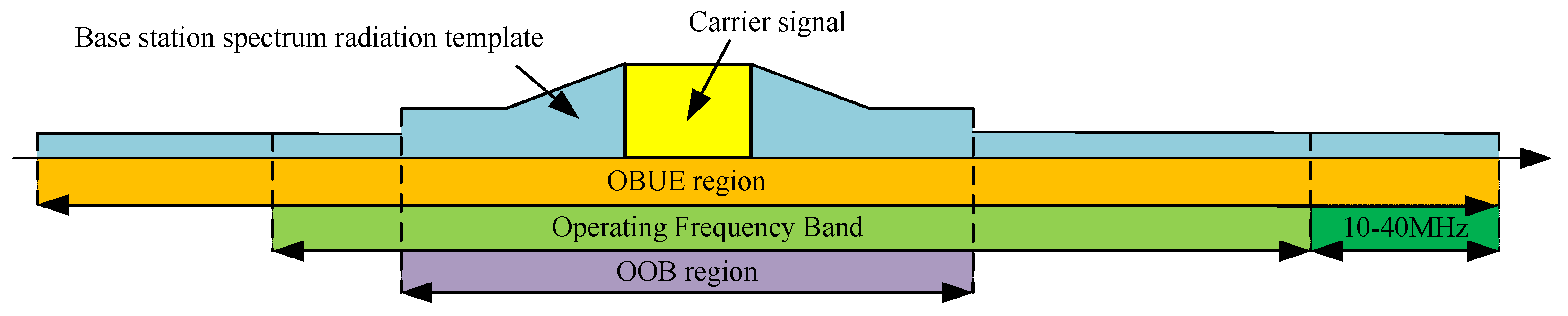
2.1.3. 5G and BeiDou B1 Band Compatibility Analysis

ITU proposes that navigation systems operating in the 1559–1610 MHz band (BeiDou B1 band) should avoid interference from other radio systems in the surrounding frequencies [31,32]. External broadband interference’s total power spectral density must comply with the corresponding protection standards for receivers in different applications. According to the 3GPP description of mobile communication signal spatial propagation, 5G signals in the propagation of the path model usually have UMi, Uma, RMa, and InH. These models usually consider the multipath effect, size scale fading for the propagation distance in a more than 50 m scenario. Using the free-space loss model if the 5G signal propagation distance is closer (less than 50 m). At the same time, the ITU recommends that when studying the interference size of other radio systems in the frequency band adjacent to the navigation signal, the spatial propagation of the interference signal should be selected using the free-space radiation model [33]:
L O S S = 20 log 10 ( f ( MHz ) ) + 20 log 10 ( d ( m ) ) 27.55
Essentially, Equation (7) is free-space path loss (FSPL). It describes the propagation loss between the BeiDou receiver antenna and the source of interference of the 5G signal. It also provides a calculation or estimation method for this nominal path loss. The nominal path loss between the antenna and interference source refers to the estimated average loss in signal power between the antenna and the source of interference, measured in decibels (dB). In wireless communication, signals experience path loss during propagation, resulting in a decrease in signal strength with increasing distance. It is a nominal or theoretically predicted value used to estimate the average path loss between the antenna and the interference source under specific conditions. Path loss occurs due to factors such as damping, scattering, and attenuation that the signal encounters during propagation through space. It can be estimated using various models based on environmental characteristics and frequency bands, to determine the attenuation of the signal.
The free-space path loss (FSPL) formula states that in a radio system consisting of a transmitting antenna transmitting radio waves to a receiving antenna, the ratio of radio wave power received P r to the power transmitted P t is:
P r P t = D t D r ( λ 4 π d ) 2
where D t is the directivity of the transmitting antenna, D r is the directivity of the receiving antenna, λ is the signal wavelength, and d is the distance between the antennas.
The distance between the antennas d must be large enough that the antennas are in the far field of each other d λ . The free-space path loss is the loss factor in this equation that is due to distance and wavelength, or in other words, the ratio of power transmitted to power received assuming the antennas are isotropic and have no directivity ( D t = D r = 1):
F S P L = ( 4 π d λ ) 2
A convenient way to express the FSPL is in terms of decibels (dB):
F S P L ( d B ) = 10 log 10 ( ( 4 π d f c ) 2 ) = 20 log 10 ( d ) + 20 log 10 ( f ) 27.55
For d,f in meters and megahertz (MHz), respectively, the constant becomes −27.55.
Based on the traversal simulation data, it can be found that if the 5G signal interferes with BeiDou, the BeiDou receiver needs to be close enough to the 5G base station. According to the path propagation model introduced by 3GPP and ITU, the nominal path loss of 5G signals should be calculated according to the free-space loss. The spatial distribution of 5G signals is calculated using Equation (7). The 5G bands adjacent to BeiDou L-bands B1, B2, and B3 are n50, n51, n74, n75, and n76, with the same NR parameters, and the frequency range of n50 covers the other four bands. The n50 upper boundary is only 45 MHz away from the BeiDou B1 signal, so it can be initially speculated that the 5G signal is located in the upper boundary of n50 when it causes the most significant impact on the BeiDou system. The impact on the BeiDou system is the greatest. When the BeiDou navigation signal is received and processed, the acquisition peak, carrier phase tracking error, and code phase tracking error can be used as important parameters to evaluate the performance of the navigation signal. The total carrier phase tracking error of BeiDou signals under the combined effect of white noise and interference is σ P L L = σ n P L L 2 + σ I P L L 2 . The code tracking error is σ D L L = σ n D L L 2 + σ I D L L 2 .
The 5G band is deployed at 2.6 GHz, far from the three frequency points of the BeiDou system. This 2.6 GHz will not affect BeiDou navigation signals. In addition, the B2 and B3 bands are also far away from the frequency interval of each band of the 5G system, so it can be presumed that there will be no compatibility problem between 5G and B2 and B3. Because the landing power of BeiDou signals is meager and has been submerged below the noise, the BeiDou system will not affect the 5G system. In summary, the study of BeiDou’s compatibility with 5G can be translated into a study of how compatible the 5G signals near the BeiDou L-band are. Among the FR1 bands, n50 has the broadest range of 5G signals near the BeiDou L-band and covers other frequency bands so that n50 can be the leading research object, and its findings can be extended to other 5G bands.
As shown in Figure 5, the n50 band is closest to the BeiDou B1 signal. Because the transmitting power of 5G base stations is generally around −10 dBw, this makes the 5G signal power on the ground much stronger than the landing power of BeiDou (−133 dBm), and even the 5G out-of-band spurious radiation at the same frequency point may be stronger than the BeiDou signal. The multi-carrier form of the 5G signal is OFDM, and its out-of-band radiation or spurious part will fall into the BeiDou B1 signal. Since QPSK and QAM modulate 5G signals, it is necessary to simulate the modulation of 5G signals by traversal. Therefore, in order to study the compatibility between BeiDou and 5G, we need to perform a traversal simulation in three dimensions:
  • The type of 5G signal.
  • The power of the 5G signal arriving at the BeiDou receiver.
  • The frequency interval between the BeiDou signal and the 5G signal.
Since performing direct acquisition of the original signal at RF frequencies is not practical, the simulation and actual acquisition should be performed at IF frequencies. The 5G system frequency points change while the nominal frequency of BeiDou is fixed. When the OB bandwidth of the n50 band is 5 MHz, and the center frequency point is located anywhere from the lower to the upper boundary of the operating band, the center frequency point of BeiDou B1I is about 47 MHz–131 MHz from the center frequency point of the 5G signal. The center frequency point of B1C is 60 MHz–145 MHz from the center frequency point of the 5G signal. In order to simulate the change in frequency interval between the BeiDou signal and the n50 signal, the 5G IF is set to 10 MHz, while the BeiDou B1I signal IF is set to 60 MHz–110 MHz, and the BeiDou B1C signal IF is set to 70 MHz–100 MHz, as shown in Figure 5.

2.2. Receiver Acquisition Algorithm Design

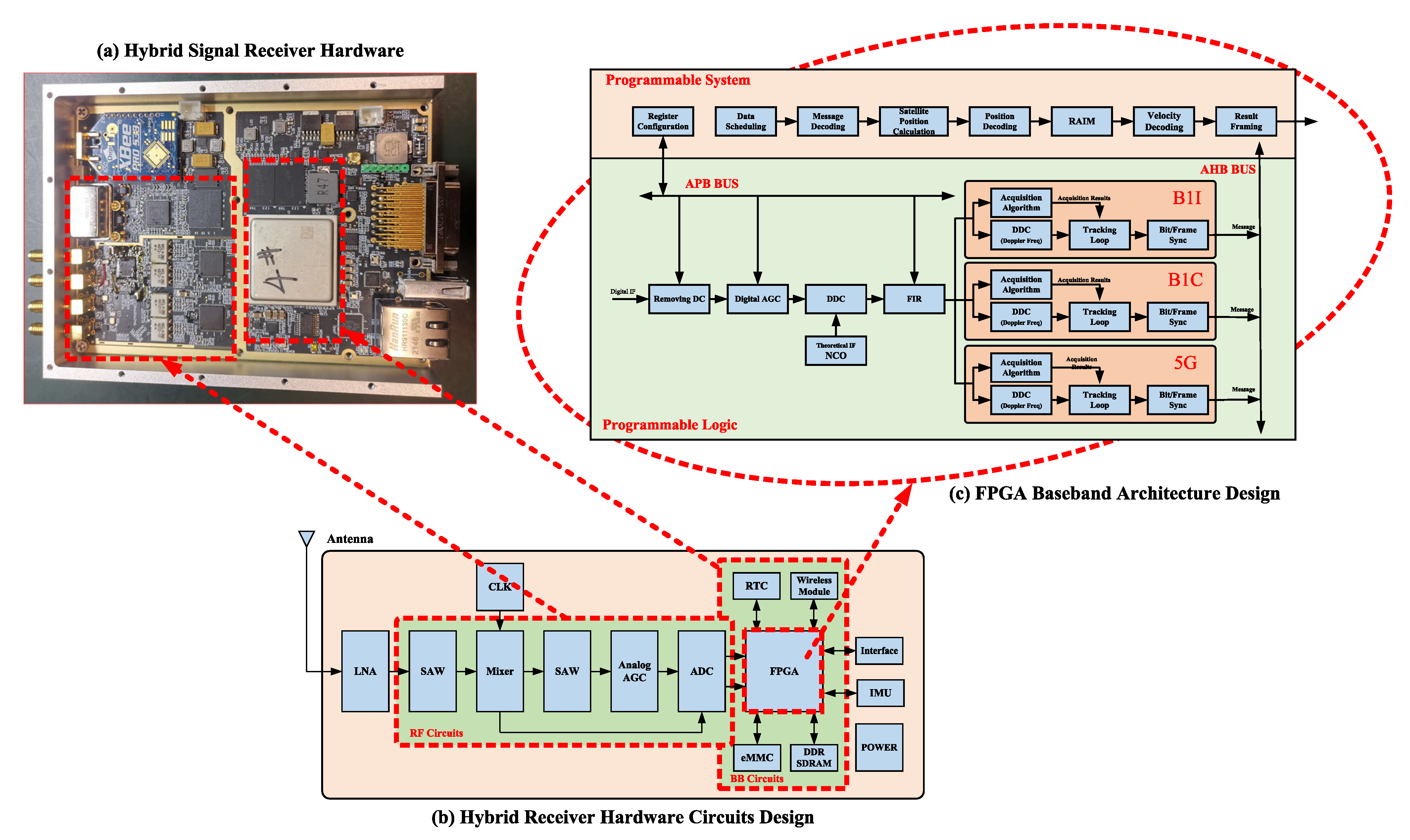
2.2.1. Receiver Hardware Architecture Design

At the signal level, Dou adopts the direct sequence spread-spectrum (DSSS) modulation scheme, while 5G employs orthogonal frequency division multiplexing (OFDM). Both schemes are based on code division multiple access (CDMA), but 5G utilizes orthogonal subcarriers for spectrum allocation and data transmission, resulting in efficient spectrum utilization and resistance to multipath fading, making it suitable for high-speed mobile and wideband communication. The BeiDou radio navigation satellite system (RNSS) signals do not require bidirectional communication, and a single-carrier approach is sufficient to meet the system design requirements. From the analysis of the signal schemes mentioned above, it can be observed that due to the resemblance between the two signal schemes, a single receiving method theoretically can be used for the reception of mixed signals from both types. This receiving method exhibits high similarity in the RF circuitry, baseband signal preprocessing, acquisition and tracking, and despreading stages. The main difference lies in the multi-carrier nature of 5G signals, which requires local generation of multiple carriers for carrier separation of the received signal. Additionally, the generation method for local pseudocodes also differs.
The hardware architecture of the mixed-signal receiver of BeiDou and 5G signals is shown in Figure 6, which is divided into RF front-end, baseband processing, and information processing. The BeiDou signal and 5G signal are received by the antenna and sent to the RF front-end processing circuit. The RF front-end circuit first amplifies the mixed signal through a low-noise amplifier (LNA), where the LNA is placed in the front position to reduce the receiver’s overall noise figure (NF). The amplified signal must also go through anti-image filtering, a power divider, a mixer, and anti-alias filtering before being captured by the ADC. After the above processing, the digital IF signal is obtained.
The high-speed digital IF signal is first digitally downconverted to obtain the digital baseband signal. The digital baseband signal is then passed through the signal acquisition algorithm, which mainly processes the carrier Doppler frequency and pseudocode phase of the BeiDou B1 and 5G signals in the signal to obtain coarse raw observation information, which is also the focus of this study. We propose a fast acquisition algorithm for the hybrid BeiDou B1 and 5G signals. This raw observation information is later sent to the baseband tracking algorithm. Based on the coarse Doppler frequency and pseudocode phase, it accurately tracks the carrier and pseudocode phases through the carrier and pseudocode loops. Finally, it restores the original carrier and pseudocode envelope. The signal processed by the tracking algorithm is the envelope of the spread-spectrum code signal. The envelope signal can extract accurate message information only after bit-synchronous and frame-synchronous processing.
In the information processing part, BeiDou signals must complete the equation solving of position, velocity, and clock difference. They can be considered accurate and trustworthy after being processed by the receiver autonomous integrity monitoring (RAIM) algorithm to be output. Furthermore, 5G signals also enter into higher-level processing after extracting frame information.
The antenna receives the hybrid signal, and the RF front-end is divided into two branches of B1 and 5G signals. The B1 signal is downconverted by RF and sampled by ADC to obtain a 20 MHz digital IF signal, and the 5G n50 signal is downconverted by RF and sampled by ADC to obtain a 120 MHz digital IF signal. The digital IF signal after ADC sampling enters baseband signal processing, and different parameter configurations are used according to the respective signal characteristics. The final output observations of the baseband processing are the pseudocode phase, carrier phase, carrier Doppler, receiver local time, and message information, which are transferred to the processor through the local bus for subsequent information processing, such as the solution of the observation equation and the conversion of the coordinate system, and finally the receiver position, receiver clock difference, receiver speed, receiver clock drift, signal carrier-to-noise ratio, and other information. The frequency allocation of the signal processing is shown in Table 8.

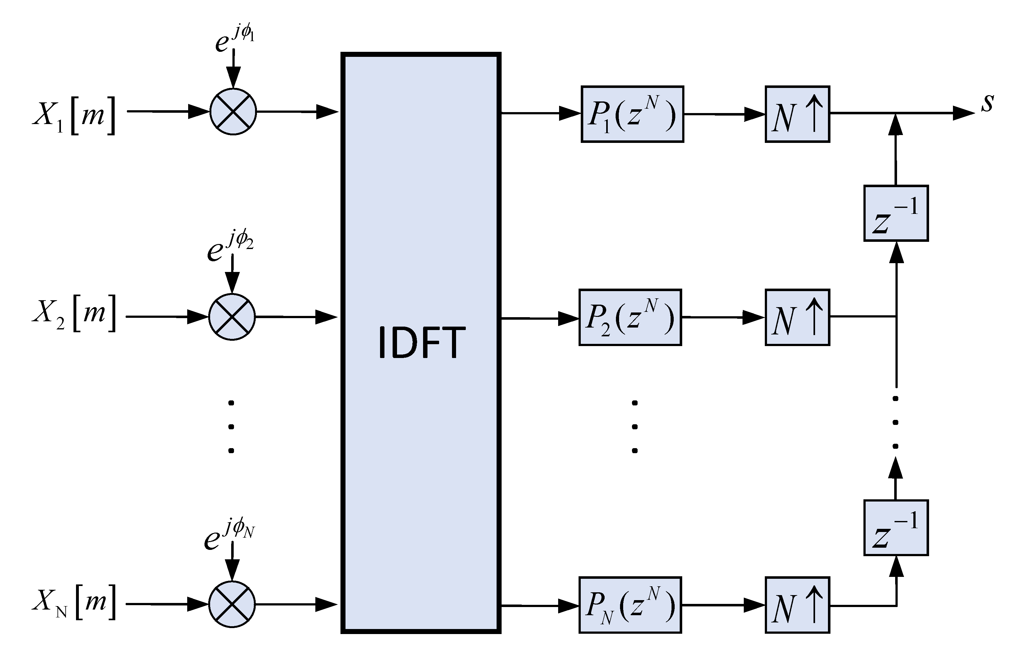
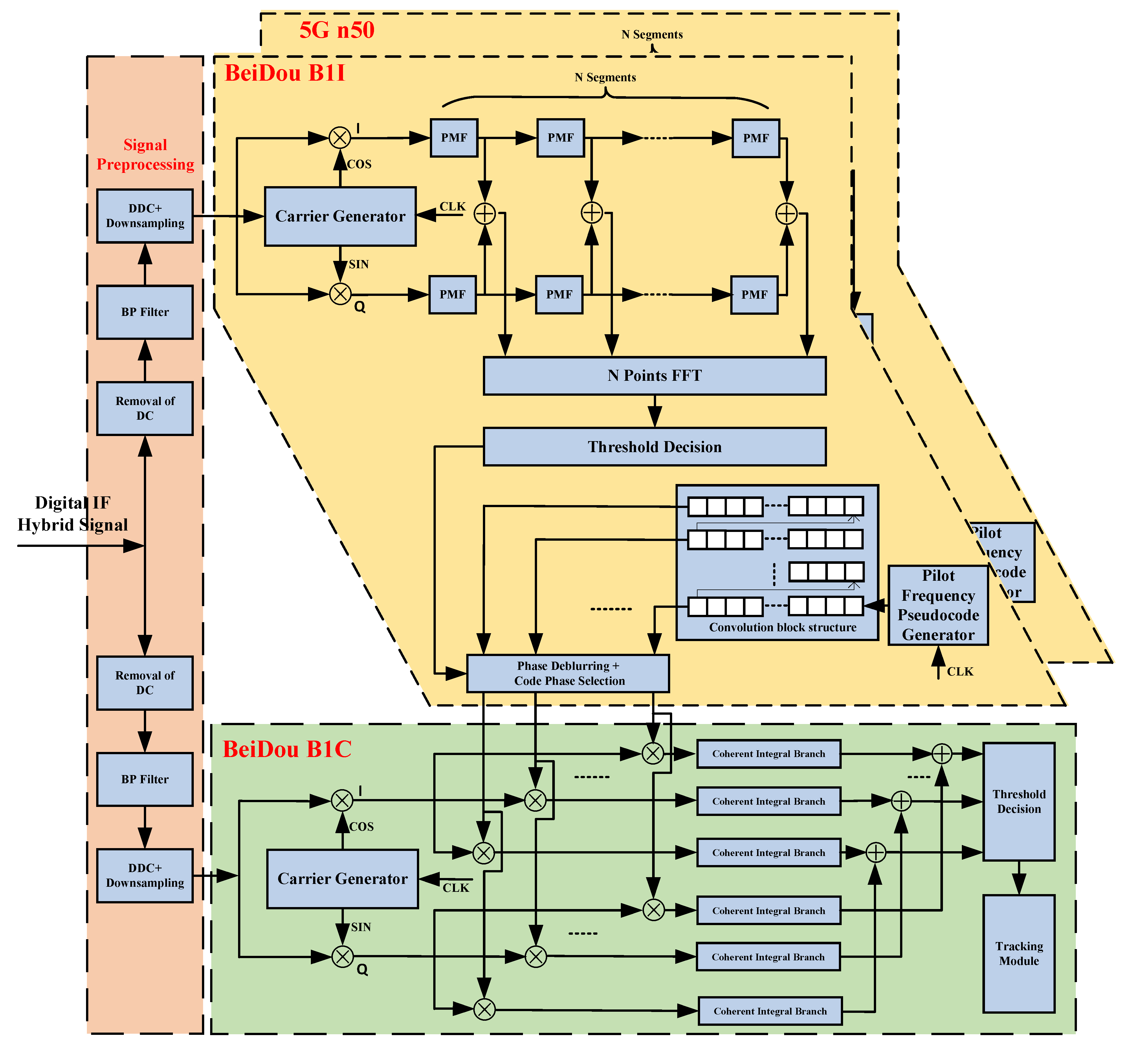
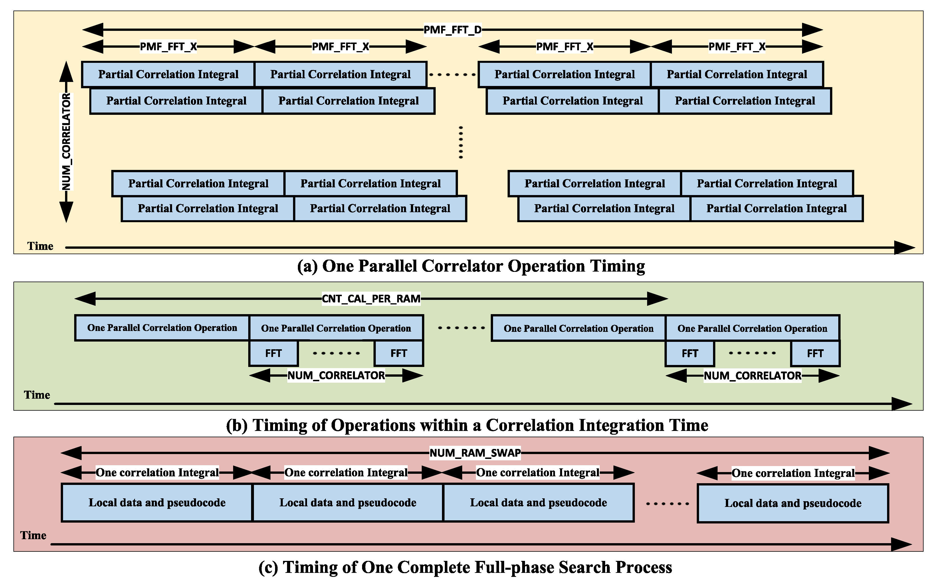
2.2.2. Receiver Hybrid Coherent Acquisition Algorithm Design

In the signal processing session, the acquisition process is the first stage of the hybrid signal processing, aiming to determine the presence of the detected signal and to obtain a rough estimate of the residual carrier frequency and code delay of the received signal, providing the necessary parameters and conditions for the initialization of the subsequent tracking stages. The acquisition’s accuracy also directly impacts the tracking performance [34], such as the loop convergence time. On the other hand, the acquisition process is one of the more time-consuming phases of baseband processing [35]. Therefore, hybrid signal reception systems must have high accuracy and fast acquisition in a weak-signal environment. In order to achieve high accuracy and fast acquisition in weak signals, we propose an SC-PMF-FFT (strong correlation partial matched filters fast Fourier transformation) acquisition algorithm based on convolutional blocks with a priori information, starting from search domain evaluation and detection. The structure of the implementation of this algorithm is shown in Figure 7. The SC-PMF-FFT algorithm consists of the signal preprocessing module, the block convolution-based code phase deblurring fast-matching filtering module, and the a priori information-based correlation integral judgment module.
In the signal preprocessing module, the digital IF signal is sequentially processed by DC removal, bandpass filtering, DDC, and downsampling. The DC removal process removes the DC component from the input signal, and the processed signal contains only an AC signal or a slight DC bias. The DDC and downsampling processes are responsible for digitally downconverting the high-sampling-rate IF signal to baseband and then extracting it at a specific ratio while ensuring that the extracted data do not suffer from spectral aliasing (downsampling rate ≥ signal main bandwidth × 2). The mathematical derivation of the specific implementation process is presented as follows:
D I ( k ) = D remove d c ( k ) cos 2 π f out k D Q ( k ) = D remove d c ( k ) sin 2 π f out k
where D remove d c ( k ) is the signal after DC removal, and f out is the local carrier frequency. Performing downsampling on D I ( k ) and D Q ( k ) :
D I d s ( n ) = f d s f s k = 1 f s f d s D I ( k ) , n = 0 , 1 , 2 , N D Q d s ( n ) = f d s f s k = 1 f s f d s D Q ( k ) , n = 0 , 1 , 2 , N
where f s is the sampling frequency, and f d s is the downsampling rate. Performing coherent integration on D I d s ( n ) and D Q d s ( n ) :
I i ( n ) = k = 0 P M F _ F F T _ X D I d s ( k + n × P M F _ F F T _ X ) C ( P M F _ F F T _ D 1 k ) Q i ( n ) = k = 0 P M F _ F F T _ X D Q d s ( k + n × P M F _ F F T _ X ) C ( P M F _ F F T _ D 1 k )
where P M F _ F F T _ X is the number of data points for partial coherent integration, P M F _ F F T _ D is the number of blocks, and C function is the local pseudocode sequence. Performing FFT processing on I i and Q i , the code phase points can be obtained at the correlation peaks:
θ C = N U M P N f s × T c × n
where θ C is the pseudocode phase point. A pseudocode period consists of N U M P N code chips. f s is the sampling rate, T c is the duration of coherent integration, and n corresponds to the number of FFT computations at the correlation peak. Similarly, the carrier Doppler value can be obtained as:
f d = m × f d s P M F _ F F T _ X × P M F _ F F T _ N , m < P M F _ F F T _ X 2 m P M F _ F F T _ N × f d s P M F _ F F T _ X × P M F _ F F T _ N , m > P M F _ F F T _ X 2
where f d refers to the carrier Doppler value, f d s is the downsampling rate, P M F _ F F T _ X is the number of data points for partial coherent integration (accumulation), and P M F _ F F T _ D is the number of points for FFT computation. The obtained θ C and f d are output and passed on to the B1C carrier compensation module and the B1C pilot code phase fixed delay module. The formula for generating the local pilot code in B1C is as follows:
W ( k ; w ) = L ( k ) L ( ( k + w ) mod N ) , k = 0 , 1 , 2 , , N 1 L ( k ) = 0 , k = 0 1 , k 0 , exists a positive integer x such that k = x 2 mod N 0 , others
where L is a Legendre sequence, and w is the phase parameter.
The two segments of Legendre sequences, each with a length of 10,230, are truncated under the control of phase parameter w. They are XORed to the desired satellite pilot code primary code sequence. After modulation with a 1.023 MHz subcarrier, the output is obtained. The code chips are sampled by a clock a downsampling rate f d s . These samples are sequentially stored Shift-FIFO circuit structures, each with a sampling depth of ( f d s / 1.023 M ) × 1023 , resulting in a fixed 1 ms code phase delay in adjacent taps. The input B1C intermediate-frequency passband communication signal is:
S X ( t ) = 2 P X s X 1 ( t ) cos 2 π f X t + φ 0 s X 2 ( t ) sin 2 π f X t + φ 0
where P X is the power of the intermediate-frequency signal, f X is the intermediate frequency, φ 0 is the initial phase of the intermediate-frequency signal, and S X is the baseband signal. s X 1 ( t ) refers to the real part of the baseband signal, s X 2 ( t ) refers to the imaginary part of the baseband signal. S X can be expressed as:
s X ( t ) = 1 2 D B 1 C _ d a t a ( t ) · C B 1 C _ d a t a ( t ) · sign sin 2 π f s c _ B 1 C _ a t + 1 11 C B 1 C _ p i l o t ( t ) · sign sin 2 π f s c _ B 1 C _ b t + j 29 44 C B 1 C _ p i l o t ( t ) · sign sin 2 π f s c _ B 1 C _ a t
where the first term represents the data component, the second term represents the pilot b component, and the third term represents the pilot a component. The output after digital downconversion (DDC) circuit processing is:
S I = 2 P X 2 s X 1 ( t ) cos 2 π f X + f I t + φ 0 + cos 2 π Δ f t + φ 0 2 P X 2 s X 2 ( t ) sin 2 π f X + f I t + φ 0 + sin 2 π Δ f t + φ 0 S Q = 2 P X 2 s X 1 ( t ) sin 2 π f X + f I t + φ 0 sin 2 π Δ f t + φ 0 + 2 P X 2 s X 2 ( t ) cos 2 π f X + f I t + φ 0 cos 2 π Δ f t + φ 0
where f I is the nominal intermediate frequency plus the B1C Doppler compensation, Δ f is the difference between the actual intermediate frequency and f I . Therefore, Δ f is an approximate value close to zero.
The block convolution-based code phase deblurring fast-matching filtering module is an acquisition algorithm for CDMA modulation methods. By adjusting the parameters of the algorithm, a balance between algorithm accuracy and execution time can be obtained. However, the algorithm is essentially only a parallel frequency algorithm, and the search for the code phase is still performed serially. This design uses multiple sets of correlators working simultaneously to compensate for this drawback. These correlators simultaneously detect multiple code phase points, playing the role of parallel code phase search. Suppose the local code phase is aligned with the code phase of the input data. In that case, the algorithm will obtain a correlation peak acquired by the subsequent detection module. The number of FFT runs and frequency points corresponding to this peak will be obtained. The number of FFT runs indicates the code phase position, and the frequency point corresponding to the correlation peak in the FFT is the Doppler frequency. The peak detection module will also estimate the signal noise power. The specific formula is as follows:
I p = 2 P X 2 T sinc ( π Δ f T ) R ( Δ τ ) sin π Δ f T + φ 0 + N I N I N 0 , σ 2 Q p = 2 P X 2 T sinc ( π Δ f T ) R ( Δ τ ) cos π Δ f T + φ 0 + N Q N Q N 0 , σ 2
To eliminate the influence of the initial phase difference φ 0 , the squares of I p and I q are summed together:
I p 2 + Q p 2 = P X 2 T 2 sinc 2 ( π Δ f T ) R 2 ( Δ τ ) + N χ 2
N is the noise term, and the result of the addition follows a non-central chi-square distribution with 2 degrees of freedom. When the correlation peak value exceeds the threshold, it is considered that the correct correlation peak has been found. The capture probability can be expressed as:
P = t h + z σ 2 e T 2 P X / 2 + z 2 2 σ 2 I 0 P X / 2 T z σ 2 d z
where I 0 is the zeroth-order Bessel function of the first.
The correlation integral judgment module based on a priori information utilizes other short-code frequency signals broadcast on the same satellite to acquire long-code pilot signals. Then, it passes the acquired results to the digital transmission channel. The principle and implementation structure of the algorithm is shown in Figure 8. The algorithm is based on the premise that the frequency signal is broadcast on the same satellite, the two signals are almost identical in terms of propagation delay, and the modulated frequencies are adjacent, as well as containing the same on-board reference clock and its propagation path to the receiver antenna, resulting in a strong correlation between the two signals, which can be used to acquire the B1I signal, and then assist in the acquisition of the B1C signal after resolving the phase ambiguity. The overall effectiveness of the algorithm is higher than the direct capture of B1C, and it avoids introducing multi-peak interference in the acquisition session.
The SC-PMF-FFT algorithm involves the configuration of many parameters, which are summarized here for the B1 and 5G signals, respectively, as well as the default values, as shown in Table 9.
Some of the parameters in the table have constraint relationships with each other, which are discussed as follows:
  • S C _ P M F _ F F T _ X determines the FFT calculation resolution = downsampling rate ÷ S C _ P M F _ F F T _ X ÷ S C _ P M F _ F F T _ N .
  • S C _ P M F _ F F T _ D = (downsampling rate × coherent integration time) ÷
    S C _ P M F _ F F T _ X , but with S C _ P M F _ F F T _ D S C _ P M F _ F F T _ N .
  • C N T _ C A L _ P E R _ R A M = operating clock ÷ (downsampling rate × coherent integration time), with the result rounded down.
  • N U M _ R A M _ S W A P = downsampling rate × coherent integration length ÷
    ( N U M _ C O R R E L A T O R × C N T _ C A L _ P E R _ R A M ), the result is rounded upwards, the reasonable choice of N U M _ C O R R E L A T O R and C N T _ C A L _ P E R _ R A M , there will be no phase secondary alignment problems. Otherwise, there may be two related peaks. Otherwise, two correlation peaks may occur.
The SC-PMF-FFT workflow is discussed in detail: Firstly, the local pseudocode goes through the N U M _ C O R R E L A T O R stage flow, and the relative data slides through N U M _ C O R R E L A T O R phase-detection points. The data and pseudocode are fed to N U M _ C O R R E L A T O R correlators simultaneously. These parallel correlators work simultaneously under the control of integration pulses, outputting one partial coherent integration result per P M F _ F F T _ X clock, and each correlator outputs P M F _ F F T _ D coherent integration results in one complete operation. In one complete operation, all correlators output a total of P M F _ F F T _ D × N U M _ C O R R E L A T O R coherent integration results; these results are stored in the Bing Bang cache according to a particular organization, the read and write operations of the Bing Bang cache do not conflict, and the data read in are read out after the complementary zero operation for the FFT operation of P M F _ F F T _ N points. The FFT results and synchronization signals are sent to the peak detection circuit at the back. Depending on the timing margin, the above operation process can be performed C N T _ C A L _ P E R _ R A M times within each coherent integration duration, that is, within one coherent integration duration, C N T _ C A L _ P E R _ R A M × N U M _ C O R R E L A T O R phase-detection points can be searched, and to thoroughly search all phase points of the data within one coherent integration duration N U M _ R A M _ S W A P sub-RAM switching operation is required. Figure 9 shows the timing diagram of the workflow described above.
Below, we present an analysis of the computational expenses associated with the receiver’s operation employing the SC-PMF-FFT capture algorithm during the capture phase. The computation cost is quantified as the aggregate of multiplier and adder computations performed by the receiver throughout the capture process. The computational burden imposed by the SC–FFT capture algorithm mainly manifests in three distinct phases: downsampling, coherent integration, and FFT.
In the downsampling process, considering the inherent multiplication operations involved in sampling, an analysis with Equation (12) indicates 2 f ds f s multiplications and 2 f ds f s additions were performed.
In coherent integration, analysis with Equation (12) indicates 2 × P M F _ F F T _ X 2 × P M F _ F F T _ D multiplications and 2 × P M F _ F F T _ X 2 × P M F _ F F T _ D additions were performed. Where P M F _ F F T _ X is the number of data points for partial coherent integration and P M F _ F F T _ D is the number of blocks.
For a radix-2 FFT, the number of complex multiplication operations α 1 and complex addition operations β 1 can be expressed as follows:
α 1 = N F F T / 2 log 2 N F F T β 1 = N F F T log 2 N F F T
One complex multiplication operation is equivalent to four real multiplications and two additions, while one complex addition operation is equivalent to two real additions. Thus, the number of multiplication operations α 2 and addition operations β 2 can be expressed as follows:
α 2 = 2 N F F T log 2 N F F T β 2 = 3 N F F T log 2 N F F T
The analysis shows that the number of multiplication operations is 2 × P M F F F T D × P M F F F T L × log 2 P M F F F T L and the number of addition operations is 3 × P M F F F T D × P M F F F T L × log 2 P M F F F T L in the FFT operation. Where P M F _ F F T _ L is the number of points for FFT computation.
Table 10 is the computation cost analysis of SC-PMF-FFT algorithm. The total multiplicative computation cost is as follows:
2 f ds f s + 2 × P M F F F T X 2 × P M F F F T D + 3 × P M F F F T D × P M F F F T L × log 2 P M F F F T L
Finally, the performance of the frequency Doppler acquisition range, Doppler frequency calculation resolution, and code phase acquisition resolution of the SC-PMF-FFT algorithm for BeiDou and 5G signals with default parameters are analyzed, as shown in Table 11.

3. Results and Discussion

3.1. Hybrid Signal Receiver Hardware Design

The mainstream hardware architectures of current communication systems are based on the software defined radio (SDR) design. The hybrid signal receiver designed in this paper also follows the same principle, as shown in Figure 10, which is the hardware of the hybrid signal receiver designed in this work.
In the RF circuit design, a dedicated RF chip is used instead of traditional discrete devices so that the LNA, filtering, mixing, analog AGC, and other functions in traditional RF can be completed by one chip, which significantly simplifies the design and debugging difficulties of the RF part and ensures consistent receiver performance.
In the baseband circuit design, using the SOPC architecture the FPGA chip replaces the traditional FPGA+DSP/ARM scheme, simplifying the design difficulty and reducing the overall power consumption. Moreover, with the SOPC architecture design methodology, the real-time signal processing and information decoding are performed by the PL and PS sides of the FPGA chip, respectively, which can bring great convenience to the baseband algorithm development and software/hardware intermodulation.
In the clock circuit design, the choice of a multi-channel, low jitter, frequency, phase-adjustable clock management chip for RF, ADC sampling, and FPGA to provide a homogeneous coherent clock can ensure the baseband performance is not degraded because of the clock.
The power supply circuit design uses a hybrid DC-DC and LDO chips scheme. An LDO power supply is used for power supply parts requiring low ripples, such as the clock part and RF part, and for high power requirements, such as the baseband part, a DC-DC power supply is used to balance the power supply quality and power requirements fully.
Several interfaces, such as RS-232, RS-485, RS-422, CAN, and 1 PPS pulse are designed to suit different applications in the interface circuit design. Considering the future differential applications and combined navigation applications, a wireless transmission module interface and IMU module interface are also designed, where the wireless transmission module interface is used to receive the reference station radio differential data or VRS public network differential data, and the IMU module interface is used for the development and application of combined navigation algorithms.

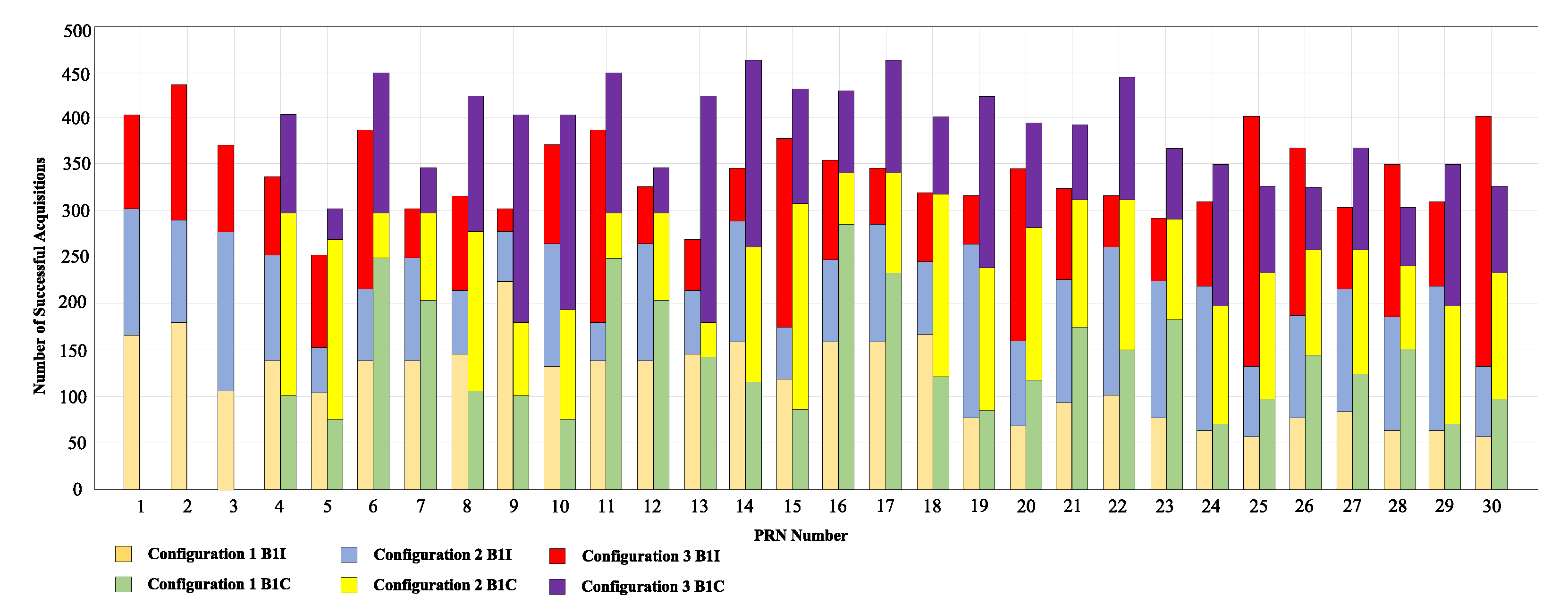
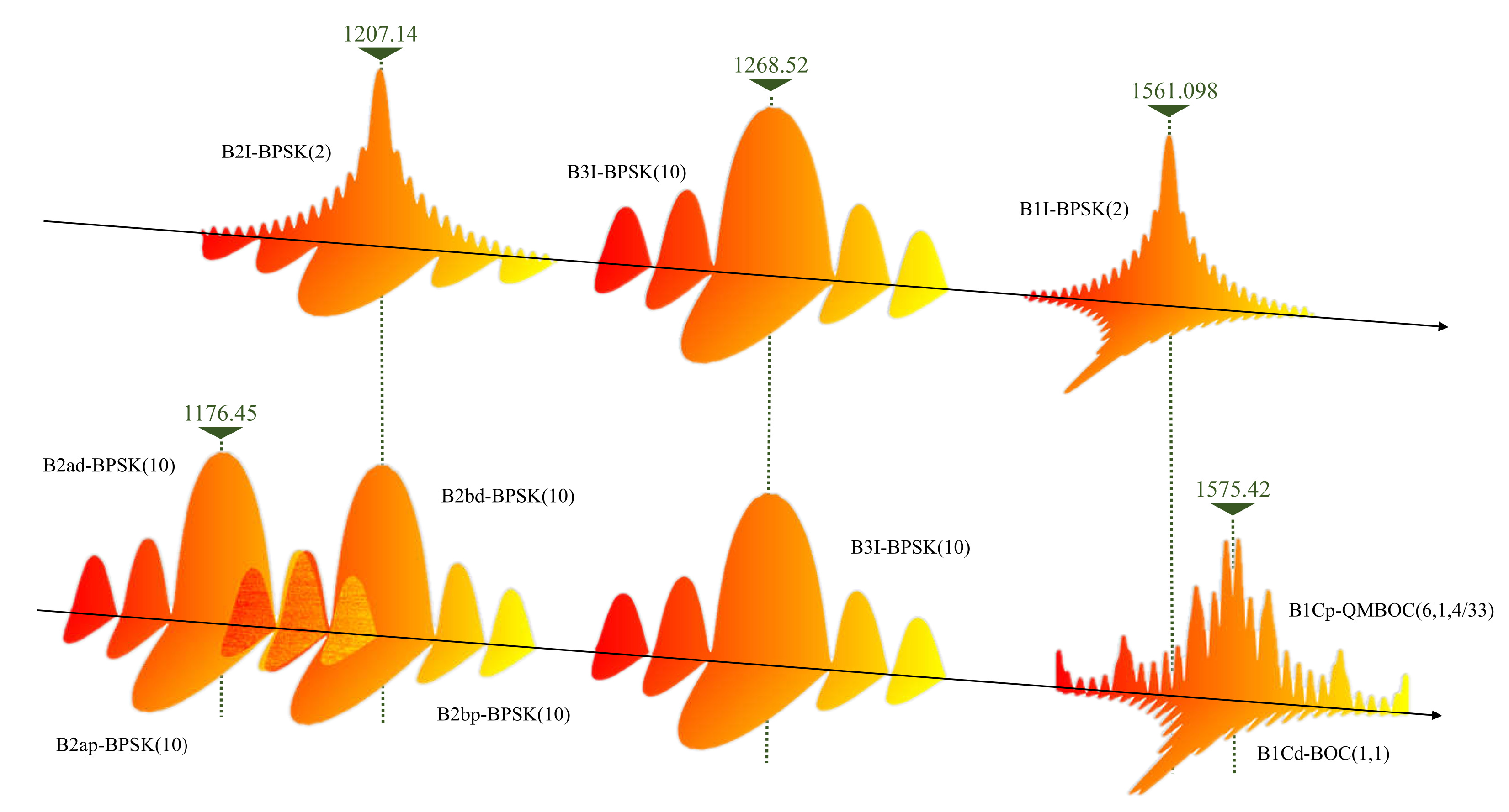
3.2. Receiver Hybrid Coherent Acquisition Performance Analysis

In this paper, we conducted practical tests on BeiDou B1 and 5G signals and statistically analyzed the resulting data. One of the test objectives is to derive the performance of the navigation receiver during regular use and to calculate the acquisition performance of B1I and B1C at this time, including the acquisition time, acquisition accuracy, and peak value of acquisition-related operations.
The RF center frequency point of the signal is 1561.098 MHz, the nominal center of B1I, the instantaneous bandwidth is 80 MHz, and the sampling rate is the same as the sampling rate of 200 MHz in the previous algorithm analysis when the actual measurement is acquired. The acquired signal contains all the navigation signals within this frequency band, including BeiDou B1I, B1C, GPS L1/CA, and Galileo. Since the acquisition location is far from an urban area, we can guarantee that the acquired signals contain only navigation signals, noise, and no other interference. At the same time, because there is no obstruction from buildings, the number of visible satellites in the collected signals is high, and enough satellite signals can be captured.
The SC-PMF-FFT algorithm enhances the acquisition sensitivity by affecting the search field evaluation and detection judgments in different parameter configurations. The actual parameters are selected considering both the real alarm rate and false alarm rate requirements and the integration length. Suppose the selected number of parallel correlator values needs to be more significant. In that case, the acquired signal that has just crossed the threshold will likely be loop-locked in the subsequent tracking, so the number of parallel correlator values can be increased to meet the theoretical requirements. The SC-PMF-FFT algorithm parameter configuration is shown in Table 12.
In the above parameter configuration, higher sensitivity can be obtained by using a more significant number of block accumulations, coherent integration times, and incoherent integration times. The test results are shown in Figure 11 and Figure 12.
In the test environment of this paper, due to the small relative speed between the terminal and the source, the residual carrier frequency of the baseband signal during the acquisition of the terminal in regular use is mainly caused by the deviation of the crystal oscillator. Such hardware-induced residual carrier frequencies are usually minor, so the positioning signal’s center frequency is adjusted to more comprehensively test the frequency acquisition accuracy of the terminal for different frequencies. Different integration settings, block accumulation, and FFT length lead to different frequency acquisition accuracies, where we set the deviation of the source frequency from the original center frequency by 300 Hz, 600 Hz, and 900 Hz, respectively. Five hundred acquisitions and tracks are performed for each deviation, and the acquisition deviations are obtained by comparing the frequency acquisition results with the results after stable tracking. The captured deviations are obtained by comparing the frequency capture results with the stable tracking results. The SC-PMF-FFT method has the highest frequency capture accuracy with this parameter setting.
The dwell time of each cell in the receiver is related to the processing speed of the receiver. Here, we first test the dwell time by connecting the receiver directly to the source. The time required to search for different code phases is obtained by adjusting the difference between the correct and code phase at the start of the acquisition. The results of the tests are shown in Table 13. The phase search time output by the receiver is subject to a particular deviation due to the lower accuracy of the processor processing time, and this deviation is more apparent when the number of phases is small. As seen from the above table, the search time increases simultaneously with the increase in the number of phase searches, and the two are close to a linear relationship. The time required for receiver initialization, start-up, and receiving and storing the required data length is 10 ms. A coherent integration of 1 ms was used in the test, and based on the subsequent correspondence between the number of phases and the search time, we can conclude that the average search for each phase takes about 0.01 ms. The capture module of the receiver is kept working and returns after each completed search round to re-search for the uncaptured signals. Therefore, when a signal is weak, it usually takes several rounds of repeated searches before capturing it. The success of signal capture is also based on whether the signal can be tracked steadily, and if the signal loses lock quickly, it needs to return to re-acquisition.

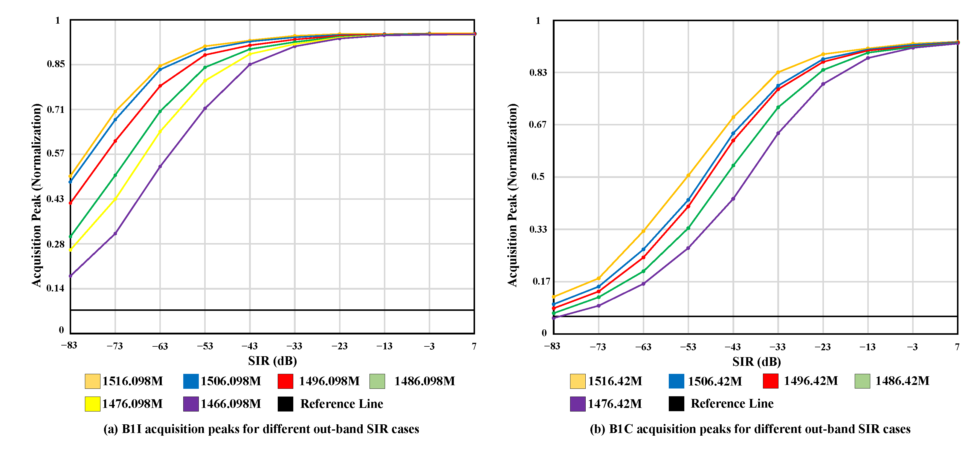
3.3. 5G Out-of-Band and B1 Signal Performance Analysis

Analyzing the B1 signal performance under 5G, out-of-band interference requires statistical quantification of the data at the end of the traversal simulation and actual measurements, including peak capture, the standard deviation of the carrier tracking output error, and the standard deviation of the code tracking output error. These parameters are the direct response to the navigation signal performance. The peak capture values of the B1I and B1C signals in different scenarios are shown in Figure 13.
Figure 13 shows that with only 5G out-of-band radiation as interference, the peak correlation for acquisition is higher than usual with only white noise, and acquisition can proceed normally, so 5G radiation does not cause much impact on acquisition. On the other hand, for the acquisition peak, the smaller the 5G power, the better the acquisition performance, and the larger the frequency interval, the better the acquisition performance. This is because the peak of the relevant operation at the acquisition time is related to the signal’s energy. Traversing the time- and frequency-domain diagrams of BeiDou B1I+5G during the simulation, we can find that as the frequency interval increases and the 5G power decreases, the energy ratio of the BeiDou B1I signal to the total signal also increases.
In Figure 13, the acquisition can still be carried out smoothly at the maximum 5G power, and the impact of the acquisition is not significant. The statistical plot of the capture follows the expected pattern, the larger the frequency interval, the better the capture performance, and the smaller the 5G power, the better the performance capture performance. This is because the capture performance is energy dependent. The time-domain and frequency-domain plots of the traversed BD B1C+5G out-of-band radiation show that the energy share of the BD signal strictly follows the more significant the frequency interval, and the smaller the 5G power, then the more significant the energy share of B1C. Therefore, the capture-related peak statistics of B1C strictly obey the expected law.
When the signal-to-interference ratio (SIR) of the 5G signal at the receiver is below −58 dB (signal power −45 dBW), it will have a substantial impact on the B1 signal of the BeiDou system. Then, according to the analysis of the 5G base station transmitting power, it is known that the 5G signal at the receiver end will exceed −45 dBw when the receiver is very close to the 5G base station. At this time, focusing on losing the 5G signal when it propagates very close to the base station is necessary. According to the recommendations proposed by ITU-R M.1318 in assessing the compatibility of navigation signals with neighboring signals, the nominal path loss of the interfering signal during propagation should be evaluated according to the free-space loss model when the interfering source is close to the receiver. In most scenarios, the 5G signal power at the receiver will be lower than −45 dBw. Only under some special conditions, when the base station radiates high power and is close to the base station, will the 5G signal power at the receiver be higher than the reference value. Then, BeiDou is compatible with 5G in most cases.

4. Conclusions

We analyze the Beidou and 5G systems’ signals starting from the signal part of the 5G out-of-band signal falling into the Beidou B1 signal band, summarize the 5G frequency band close to the Beidou signal, discuss the NR spectrum characteristics and radiation characteristics of 5G, and analyze the current ITU protection standards for navigation signals. We provide a detailed analysis of the mixed-signal and frequency planning and design a hybrid receiver architecture compatible with both movements. We provide a detailed analysis of the hybrid signal regime and frequency planning and create a hybrid receiver architecture compatible with both signals, including the hardware design of the RF front-end circuit, clock circuit, baseband circuit, and interface circuit. We propose a strong-correlation-based SC-PMF-FFT fast capture algorithm, which takes advantage of the strong correlation of signals broadcast on the B1 frequency point of BeiDou, performs fast decoding phase ambiguity processing for strongly correlated signals from B1I to B1C, and reuses the structure of the CDMA system signal capture algorithm to complete fast capture of 5G signals using the OFDM system. Experiments show that the method can achieve a capture sensitivity of −154 dBm for BeiDou B1 signals with a whole constellation capture time of no more than 40 ms when the inlet power of 5G signals does not exceed −45 dBw.

Author Contributions

Conceptualization, X.Y. (Xu Yang 1) and C.Z.; methodology, W.F.; software, X.Y. (Xu Yang 1) and S.H.; validation, X.Y. (Xu Yang 1), Z.Y. and Q.W.; formal analysis, C.Z.; investigation, X.Y. (Xu Yang 2); resources, X.Y. (Xu Yang 2) and S.H.; data curation, X.Y. (Xu Yang 2); writing—original draft preparation, X.Y. (Xu Yang 1) and S.H.; writing—review and editing, X.Y. (Xu Yang 1) and C.Z.; visualization, X.Y. (Xu Yang 2); supervision, C.Z.; project administration, W.F. All authors have read and agreed to the published version of the manuscript.

Funding

This research was funded by the National Natural Science Foundation of China, under grant number 61901015.

Institutional Review Board Statement

Not applicable.

Informed Consent Statement

Not applicable.

Data Availability Statement

Not applicable.

Acknowledgments

The authors acknowledge graduate student Xu Yang for his contribution to literature search and collation.

Conflicts of Interest

The authors declare no conflict of interest.

Abbreviations

The following abbreviations are used in this manuscript:
FPGAField programmable gate array
DSPDigital signal processing
GPUGraphics processing unit
DSPsDigital signal processors
DRAMDynamic random access memory
MCMMMixed mode clock manager
PLLPhase lock loop
FIFOFirst input first output
ADCAnalog-to-digital converter
BDSBeiDou navigation satellite system
BPSKBinary phase shift keying
CNRCarrier to noise ratio
CDMACode division multiple access
DLLDelay lock loop
DSSS-CDMADirect-sequence spread-spectrum code division multiple access
ELSEarly late slope
EKFExtend Kalman filter
FDDFrequency division duplexing
FFTFast Fourier transformation
FIRFinite impulse response
FLLFrequency-locked loop
GalileoGalileo satellite navigation system
GLONASSGlobal navigation satellite system
GNSSGlobal navigation satellite system
GPSGlobal positioning system
HRCHigh-resolution correlator
IFFTInverse fast Fourier transformation
LNALow-noise amplifier
LPFLow pass filter
MSEMean squared error
MIMOMultiple input multiple outputs
NCONumerically controlled oscillator
OFDMOrthogonal frequency division multiplexing
PMFPartial matched filters
PNTPositioning navigation and timing
PPSPulse per second
PRNPseudorandom noise
QAMQuadrature amplitude modulation
SASelective availability
SNRSignal-to-noise ratio
TDDTime division duplexing
TD-SCDMATime division synchronous code division multiple access
UWBUltra wideband
WGNWhite Gaussian noise

References

  1. del Peral-Rosado, J.A.; Nolle, P.; Rothmaier, F.; Razavi, S.M.; Lindmark, G.; Jiang, X.; Shrestha, D.; Gunnarsson, F.; Parsawar, S.; Mundlamuri, R.; et al. Proof-of-Concept of Dedicated Aerial 5G and GNSS Testbed for Enhanced Hybrid Positioning. In Proceedings of the 35th International Technical Meeting of the Satellite Division of The Institute of Navigation (ION GNSS+ 2022), Denver, CO, USA, 19–23 September 2022; pp. 2362–2376. [Google Scholar]
  2. Fabius, M.; Lapeyre, D.; Messager, F.; Kiely, I.; Arzel, L.; Pomies, A. GEONAV IoT-Study of Hybrid 5G/GNSS Positioning. In Proceedings of the 34th International Technical Meeting of the Satellite Division of The Institute of Navigation (ION GNSS+ 2021), St. Louis, MO, USA, 20–24 September 2021; pp. 725–752. [Google Scholar]
  3. Tong, W.; Zou, D.; Han, T.; Zhang, X.; Shen, P.; Lu, X.; Wang, P.; Yin, T. A New Type of 5G-Oriented Integrated BDS/SON High-Precision Positioning. Remote Sens. 2021, 13, 4261. [Google Scholar] [CrossRef]
  4. Wang, W.; Chen, T.; Ding, R.; Seco-Granados, G.; You, L.; Gao, X. Location-based timing advance estimation for 5G integrated LEO satellite communications. IEEE Trans. Veh. Technol. 2021, 70, 6002–6017. [Google Scholar] [CrossRef]
  5. Famili, A.; Foruhandeh, M.; Atalay, T.; Stavrou, A.; Wang, H. GPS Spoofing Detection by Leveraging 5G Positioning Capabilities. In Proceedings of the 2022 IEEE Latin-American Conference on Communications (LATINCOM), Rio de Janeiro, Brazil, 30 November–2 December 2022; pp. 1–6. [Google Scholar]
  6. Zhang, W.; Yang, Y.; Zeng, A.; Xu, Y. A GNSS/5G integrated three-dimensional positioning scheme based on D2D communication. Remote Sens. 2022, 14, 1517. [Google Scholar] [CrossRef]
  7. Klus, R.; Talvitie, J.; Valkama, M. Neural network fingerprinting and GNSS data fusion for improved localization in 5G. In Proceedings of the 2021 International Conference on Localization and GNSS (ICL-GNSS), Tampere, Finland, 1–3 June 2021; pp. 1–6. [Google Scholar]
  8. Guidotti, A.; Vanelli-Coralli, A.; Conti, M.; Andrenacci, S.; Chatzinotas, S.; Maturo, N.; Evans, B.; Awoseyila, A.; Ugolini, A.; Foggi, T.; et al. Architectures and key technical challenges for 5G systems incorporating satellites. IEEE Trans. Veh. Technol. 2019, 68, 2624–2639. [Google Scholar] [CrossRef] [Green Version]
  9. Qi, S.; Guo, C.; Guo, W.; Deng, C.; Liu, J. Structure and performance analysis of fusion positioning system with a single 5G station and a single GNSS satellite. Geo-Spat. Inf. Sci. 2023, 26, 94–106. [Google Scholar]
  10. Chaloupka, Z.; Ries, L.; Samperi, A.; Waller, P.; Crisci, M. Phase synchronization for 5G using mass market GNSS receivers. In Proceedings of the 2018 European Frequency and Time Forum (EFTF), Torino, Italy, 10–12 April 2018; pp. 192–196. [Google Scholar]
  11. Jin, C.; Tay, W.P.; Zhao, K.; Ling, K.V.; Sin, K.K. A 5G/GNSS Integrated Positioning Method. In Proceedings of the 35th International Technical Meeting of the Satellite Division of The Institute of Navigation (ION GNSS+ 2022), Denver, CO, USA, 19–23 September 2022; pp. 2429–2443. [Google Scholar]
  12. Shamaei, K.; Kassas, Z.M. Receiver design and time of arrival estimation for opportunistic localization with 5G signals. IEEE Trans. Wirel. Commun. 2021, 20, 4716–4731. [Google Scholar] [CrossRef]
  13. Li, F.; Tu, R.; Hong, J.; Zhang, S.; Liu, M.; Lu, X. Performance Analysis of BDS–5G Combined Precise Point Positioning. Remote Sens. 2022, 14, 3006. [Google Scholar] [CrossRef]
  14. Bai, L.; Sun, C.; Dempster, A.G.; Zhao, H.; Cheong, J.W.; Feng, W. GNSS-5G hybrid positioning based on multi-rate measurements fusion and proactive measurement uncertainty prediction. IEEE Trans. Instrum. Meas. 2022, 71, 1–15. [Google Scholar] [CrossRef]
  15. Pan, D.; Liu, W.; Yuan, H.; Ge, J. High-precision time synchronization networking algorithm for 5G base station based on GNSS. Syst. Eng. Electron. 2020, 42, 2107–2115. [Google Scholar]
  16. Destino, G.; Saloranta, J.; Seco-Granados, G.; Wymeersch, H. Performance analysis of hybrid 5G-GNSS localization. In Proceedings of the 2018 52nd Asilomar Conference on Signals,Systems, and Computers, Pacific Grove, CA, USA, 28–31 October 2018; pp. 8–12. [Google Scholar]
  17. Lukcin, I.; Duong, P.; Dietmayer, K.; Ali, S.U.; Kram, S.; Seitz, J.; Felber, W. A combined ray tracing simulation environment for hybrid 5G and GNSS positioning. In Proceedings of the 2021 International Conference on Localization and GNSS (ICL-GNSS), Tampere, Finland, 1–3 June 2021; pp. 1–6. [Google Scholar]
  18. Del Peral-Rosado, J.A.; Nolle, P.; Razavi, S.M.; Lindmark, G.; Shrestha, D.; Gunnarsson, F.; Kaltenberger, F.; Sirola, N.; Särkkä, O.; Roström, J.; et al. Design considerations of dedicated and aerial 5G networks for enhanced positioning services. In Proceedings of the 2022 10th Workshop on Satellite Navigation Technology (NAVITEC), Virtual, 5–7 April 2022; pp. 1–12. [Google Scholar]
  19. Li, F.; Tu, R.; Hong, J.; Zhang, S.; Zhang, P.; Lu, X. Combined positioning algorithm based on BeiDou navigation satellite system and raw 5G observations. Measurement 2022, 190, 110763. [Google Scholar] [CrossRef]
  20. Li, F.; Tu, R.; Han, J.; Zhang, S.; Liu, M.; Lu, X. Performance research of real-time kinematic/5G combined positioning model. Meas. Sci. Technol. 2022, 34, 035115. [Google Scholar] [CrossRef]
  21. Zhao, J.; Fu, X.; Yang, Z.; Xu, F. Radar-assisted UAV detection and identification based on 5G in the Internet of Things. Wirel. Commun. Mob. Comput. 2019, 2019, 2850263. [Google Scholar] [CrossRef] [Green Version]
  22. Alghisi, M.; Biagi, L. Positioning with GNSS and 5G: Analysis of Geometric Accuracy in Urban Scenarios. Sensors 2023, 23, 2181. [Google Scholar] [CrossRef] [PubMed]
  23. Shang, P.; Wang, X.; Zou, D.; Chu, Z.; Guo, Y. Acquisition performance of B1I abounding with 5G signals. J. Syst. Eng. Electron. 2022, 33, 563–574. [Google Scholar] [CrossRef]
  24. Jia, M.; Kassas, Z.M. Kalman Filter-Based Integrity Monitoring for GNSS and 5G Signals of Opportunity Integrated Navigation. IFAC-PapersOnLine 2022, 55, 273–278. [Google Scholar] [CrossRef]
  25. del Peral-Rosado, J.A.; Saloranta, J.; Destino, G.; López-Salcedo, J.A.; Seco-Granados, G. Methodology for simulating 5G and GNSS high-accuracy positioning. Sensors 2018, 18, 3220. [Google Scholar] [CrossRef] [PubMed] [Green Version]
  26. Mata, F.; Grec, F.; Azaola, M.; Blázquez, F.; Fernández, A.; Dominguez, E.; Cueto-Felgueroso, G.; Seco-Granados, G.; del Peral-Rosado, J.; Staudinger, E.; et al. Preliminary field trials and simulations results on performance of hybrid positioning based on GNSS and 5G signals. In Proceedings of the 33rd International Technical Meeting of the Satellite Division of The Institute of Navigation (ION GNSS+ 2020), Online, 22–25 September 2020; pp. 387–401. [Google Scholar]
  27. China Satellite Navigation Office. BeiDou Navigation Satellite System Signal in Space Interface Control Document Open Service Signal B1C (Version 1.0); China Satellite Navigation Office: Beijing, China, 2017. [Google Scholar]
  28. China Satellite Navigation Office. BeiDou Navigation Satellite System Signal in Space Interface Control Document Open Service Signal B1I (Version 3.0); China Satellite Navigation Office: Beijing, China, 2019. [Google Scholar]
  29. China Satellite Navigation Office. BeiDou Navigation Satellite System Signal in Space Interface Control Document Open Service Signal B2a (Version 1.0); China Satellite Navigation Office: Beijing, China, 2017. [Google Scholar]
  30. China Satellite Navigation Office. BeiDou Navigation Satellite System Signal in Space Interface Control Document Open Service Signal B3I (Version 1.0); China Satellite Navigation Office: Beijing, China, 2018. [Google Scholar]
  31. Henri, Y.; Matas, A. RNSS and the ITU radio regulations. In Proceedings of the InsideGNSS, Red Bank, NJ, USA, 1 January 2018; pp. 32–39. [Google Scholar]
  32. Series, M. Recommendation ITU-R M.1903-1, 2019. Available online: https://www.itu.int/dms_pubrec/itu-r/rec/m/R-REC-M.1903-1-201909-I!!PDF-E.pdf (accessed on 29 June 2023).
  33. Series, M. Recommendation ITU-R M.1318-1, 2007. Available online: https://www.itu.int/dms_pubrec/itu-r/rec/m/R-REC-M.1318-1-200710-I!!PDF-E.pdf (accessed on 29 June 2023).
  34. Tamazin, M.; Noureldin, A.; Korenberg, M.J.; Massoud, A.; Navigation and Instrumentation Research Group. Robust fine acquisition algorithm for GPS receiver with limited resources. GPS Solut. 2016, 20, 77–88. [Google Scholar] [CrossRef]
  35. Jan, S.S.; Lin, Y.C. A new multi-C/A code acquisition method for GPS. GPS Solut. 2009, 13, 293–303. [Google Scholar] [CrossRef]
Figure 1. Organization of this paper.
Applsci 13 07818 g001
Figure 2. Diagram of BeiDou signal distribution.
Applsci 13 07818 g002
Figure 3. Implementation principle of FBMC with N subcarriers.
Applsci 13 07818 g003
Figure 4. Base station operating band unwanted radiation frequency applicable range.
Applsci 13 07818 g004
Figure 5. (a) Diagram of the corresponding BeiDou B1I signal and n50 radio frequency during simulation. (b) Diagram of the corresponding BeiDou B1C signal and n50 radio frequency during simulation.
Applsci 13 07818 g005
Figure 6. Receiver hardware architecture.
Applsci 13 07818 g006
Figure 7. The structure of the SC-PMF-FFT algorithm.
Applsci 13 07818 g007
Figure 8. Obtaining the code phase ambiguity point of B1C from the a priori information of the B1I signal.
Applsci 13 07818 g008
Figure 9. (a) One parallel correlator operation timing. (b) Timing of operations within a correlation integration time. (c) Timing of one complete full-phase search process.
Applsci 13 07818 g009
Figure 10. (a) Hybrid signal receiver hardware. (b) Hybrid receiver hardware circuits design. (c) FPGA baseband architecture design.
Applsci 13 07818 g010
Figure 11. (a) B1I signal tracking status for 6 baseband channels. (b) B1C signal tracking status for 6 baseband channels. (c) Successful acquisition of B1I signal from satellite 25. (d) Successful acquisition of B1C signal from satellite 25.
Applsci 13 07818 g011
Figure 12. SC-PMF-FFT algorithm acquisition time test results under different configurations.
Applsci 13 07818 g012
Figure 13. (a) B1I acquisition peaks for different out-of-band SIR cases. (b) B1C acquisition peaks for different out-of-band SIR cases.
Applsci 13 07818 g013
Table 1. BeiDou signal basic parameters.
SignalModulationPN Code Length
(Chips)
PN Code Rate
(Mcps)
Message Rate
(bps)
Spread Spectrum
Gain (dB)
B1IBPSK20462.046D1:50
D2:500
33.1
B1CBOC(1,1)
QMBOC(6,1,4/33)
10,2301.02310040.1
B2aBPSK(10)
BPSK(10)
10,23010.2320047.1
B2bBPSK(10)10,23010.2320047.1
B3IBPSK10,23010.23D1:50
D2:500
40.1
Table 2. BeiDou signal message types and broadcasting methods.
Signal NameB1IB1CB2aB2bB3I
Message TypeD1/D2B-CNAV1B-CNAV2B-CNAV3D1/D2
Broadcast MethodD1:MEO/IGSO
D2:GEO
MEO/IGSOMEO/IGSOMEO/IGSOD1:MEO/IGSO
D2:GEO
Table 3. The B1C signal structure.
ComponentModulationPhase RelationshipPower Ratio
S B 1 C d a t a ( t )
Sine BOC ( 1 , 1 )
01/4
S B 1 C p i l o t a ( t )
QMBOC ( 6 , 1 , 4 / 33 )
Sine BOC ( 1 , 1 )
9029/44
S B 1 C p i l o t b ( t )
Sine BOC ( 6 , 1 )
01/11
Table 4. 5G FR1 frequency band details.
NR Frequency BandUplink Frequency Band
(MHz)
Downlink Frequency Band
(MHz)
Duplex Mode
n11920–19802110–2170FDD
n21850–19101930–1990FDD
.......................
n501432–15171432–1517TDD
n511427–14321427–1432TDD
.......................
n741427–14701475–1518FDD
n75N/A1432–1517SDL
n76N/A1427–1432SDL
........................
n952010–2025N/ASUL
Table 5. 5G band transmission bandwidth configuration.
SCS
(KHz)
5 MHz10 MHz15 MHz20 MHz70 MHz80 MHz90 MHz100 MHz
NRBNRBNRBNRBNRBNRBNRBNRB
15255279106N/AN/AN/AN/A
3011243851189217245273
60N/A11182493107121135
Table 6. 5G signal band near BeiDou.
NR Frequency BandUplink Frequency Band
(MHz)
Downlink Frequency Band
(MHz)
Duplex Mode
n501432–15171432–1517TDD
n511427–14321427–1432TDD
n741427–14701475–1518FDD
n75N/A1432–1517SDL
n76N/A1427–1432SDL
n92832–8621432–1517FDD
n93880–9151427–1432FDD
n94880–9151432–1517FDD
Table 7. 5G NR specification.
Key TechnologyDescription
Duplex modeFDD/TDD
Basic waveformDownlink: CP-OFDM/Uplink: CP-OFDM, DFT-S-OFDM
Carrier bandwidthBelow 6 GHz: 100 MHz max/Above 6 GHz: 400 MHz max
Modulation modeQPSK, 16QAM, 64QAM, 256QAM
Subcarrier intervalBelow 6 GHz: 15 KHz, 30 KHz, 60 KHz/Above 6 GHz: 60 KHz, 120 KHz, 240 KHz
Table 8. Hybrid signal frequency allocation.
BeiDou B1 (MHz)5G n50 (MHz)
RF1561.098∼1575.421427∼1517
Baseband IF20.46120
Local Oscillator Frequency1540.6381592
Baseband BandWidth4.09290
Baseband BandWidth/22.04645
RF Range1559.052∼1577.4661427∼1517
Baseband IF Range18.414∼22.50675∼165
ADC Sampling Rate20.46200
Table 9. SC-PMF-FFT algorithm parameters.
ParameterBeiDou B15G n50
Operating Clock120 MHz120 MHz
Downsampling Rate30 MHz90 MHz
Coherent Integration Time1 ms5 ms
Number of Partial Coherent Integration ( S C _ P M F _ F F T _ X )6003000
Number of Chunks ( S C _ P M F _ F F T _ D )20100
Number of Points of FFT ( S C _ P M F _ F F T _ N )128128
Number of Parallel Correlators ( N U M _ C O R R E L A T O R )60300
Number of Parallel Correlators within Each Correlation Integration ( C N T _ C A L _ P E R _ R A M )51
Number of RAM Switches of the Data within the Correlation Integration ( N U M _ R A M _ S W A P )401000
Table 10. SC-PMF-FFT Algorithm for computation cost analysis.
Calculation StepsMultiplier Computation CostAdder Computation Cost
Downsampling 2 f ds f s 2 f ds f s
Coherent Integration 2 × P M F F F T X 2 × P M F F F T D 2 × P M F F F T X 2 × P M F F F T D
FFT 2 × P M F F F T D × P M F F F T L × log 2 P M F F F T L 3 × P M F F F T D × P M F F F T L × log 2 P M F F F T L
Total 2 f ds f s + 2 × P M F F F T X 2 × P M F F F T D + 2 × P M F F F T D × P M F F F T L × log 2 P M F F F T L 2 f ds f s + 2 × P M F F F T X 2 × P M F F F T D + 3 × P M F F F T D × P M F F F T L × log 2 P M F F F T L
Table 11. SC-PMF-FFT algorithm for different signal acquisition performance analysis.
Coherent
Integration
Time (ms)
Search Data
Phase Point
XDNDoppler
Range (KHz)
Effective
Doppler
Range (KHz)
Doppler
Calculation
Resolution (Hz)
Code
Phase
Resolution (Chip)
B1I112,00060020128−10∼+10−2.5∼+2.5156.250.1705
B1C160,000600100128−50∼+50−12.5∼+12.5781.250.1705
5G n50112,00060020128−10∼+10−2.5∼+2.5156.250.1705
Table 12. SC-PMF-FFT algorithm parameter configuration in the acquisition sensitivity test.
Coherent
Integration
Time (ms)
Search Data
Phase Point
SC_PMF_FFT_XSC_PMF_FFT_DSC_PMF_FFT_NDoppler
Calculation
Resolution (Hz)
Code Phase
Resolution
(Chip)
Configuration 1112,0006002012878.1250.1705
Configuration 2224,000600100128156.250.3410
Configuration 3560,000600500128312.500.8525
Table 13. SC-PMF-FFT algorithm acquisition sensitivity test.
C/No (dB·Hz)Number of AcquisitionsSuccess RatePhase Search Time (ms)
300 Hz600 Hz900 Hz
38.9500100.0%257
35.9500100.0%257
32.949899.6%41015
29.948396.6%51116
26.943286.4%102040
23.935971.8%152960
20.926152.2%4793121
17.914629.2%289465567
Disclaimer/Publisher’s Note: The statements, opinions and data contained in all publications are solely those of the individual author(s) and contributor(s) and not of MDPI and/or the editor(s). MDPI and/or the editor(s) disclaim responsibility for any injury to people or property resulting from any ideas, methods, instructions or products referred to in the content.

