Article

Liquid for Fused Deposition Modeling Technique (L-FDM)—A Revolution in Application Chemicals to 3D Printing Technology: Color and Elements

1
Centre for Advanced Technologies, Adam Mickiewicz University in Poznań, 10 Uniwersytetu Poznańskiego, 61-614 Poznań, Poland
2
Faculty of Chemistry, Adam Mickiewicz University in Poznań, 8 Uniwersytetu Poznańskiego, 61-614 Poznań, Poland
*
Authors to whom correspondence should be addressed.
Appl. Sci. 2023, 13(13), 7393; https://doi.org/10.3390/app13137393
Submission received: 23 May 2023 / Revised: 18 June 2023 / Accepted: 20 June 2023 / Published: 21 June 2023
(This article belongs to the Special Issue Multidimensional Additive Manufacturing)

Abstract

:

Featured Application

The L-FDM technique enables the direct introduction of chemicals, dyes, radioactive substances, pesticides, antibiotics, nanoparticles, trace elements, fertilizers, phosphors, monomers for polymerization, proteins, peptides, and active ingredients in the direct printing process from a polymer material with a typical FDM printer. With the proposed technology, it is now possible to introduce chemical substances into polymer filaments that were previously impossible to apply due to undergoing physical or chemical transformations during previous processing processes. This article discusses methods that eliminate the need for costly and energy-consuming processing equipment. These methods can be utilized in any laboratory by users without access to specialized devices.

Abstract

This article presents a novel 3D printing technique called L-FDM (liquid for fused deposition modeling), which is based on the deposition of molten thermoplastic material. The new method allows for the direct introduction of chemicals and polymer filament modifications during the printing process. In contrast to traditional incremental methods, L-FDM eliminates the need for extra granulating, extrusion, and processing equipment, making it possible to introduce chemical additives to the polymer matrix directly. This opens up exciting possibilities for chemical laboratories to test and experiment with new and known chemicals through 3D printing. The article discusses the technical aspects of L-FDM and its potential applications and provides practical examples of direct filament modifications using the technique. The results of these modifications were verified using a colorimeter, electron microscopy (SEM/EDS), and optical microscopy.

1. Introduction

1.1. State-of-the-Art

Since the 1980s, there has been a rise in contemporary additive manufacturing (AM) technologies, commonly referred to as 3D printing. These technologies enable the use of a wide range of materials, including polymers, metals, ceramics, food, and biomaterials [1]. Three-dimensional printing provides several benefits, such as the ability to produce objects directly without the need for a complete technological infrastructure, the capacity to manufacture products with complex geometries, design flexibility, cost-effective use of materials, and eco-friendliness [2]. Among the various AM techniques, the most significant methods are stereolithography (SLA), selective laser sintering (SLS), and fused deposition modeling (FDM). Stereolithography based on photopolymerization was the first method developed by additives, using UV-cured resins as the building material [3].
Compared to other methods, this technique is known for its high accuracy in producing objects without post-processing. The SLS method is a printing technology based on a powder polymer. In this method, the laser beam moves along a specific path and sinters the polymer powder under the influence of the generated heat in layers until reaching a three-dimensional model [4]. Fused deposition modeling or fused filament fabrication (FDM/FFF) was developed in 1988 by Scot Crump, founder of Stratasys, and marketed under the name FDM (US Patent No. 5 738 817). In the process, we use a thermoplastic filament as the building material, which is mounted on a spool and fed to the head, where it reaches the appropriate melting temperature. Printing consists of depositing molten material through a nozzle of a certain diameter layer by layer until a three-dimensional object of the desired shape and geometry is reached [5,6]. FDM technology using thermoplastic filament is the most preferred in industrial applications. The FDM method is the most preferred of all those mentioned due to the low cost of devices (3D printers) and easy availability, low price, and variety of filaments. From a technical perspective, 3D printing technology is a very important conceptual element of the fourth industrial revolution or Industry 4.0. It brings many benefits, such as digital data transfer, remote access, minimal human intervention, the ability to develop complex geometries and intelligent materials, less waste generation, and lower final processing requirements. All these features fit perfectly into the goals of Industry 4.0 [7]. Furthermore, they meet the growing market requirements, which include rapidly changing customer requirements, a demand for high-quality products at the lowest possible production costs, especially in low-volume production scenarios, and the production of products for the needs of individual entities [2].
Although 3D printers are becoming more common in households, their potential use in scientific laboratories is often underestimated by researchers, and their application as laboratory equipment is not considered. These devices can be very useful in many different types of laboratories, from chemical to biological, pharmaceutical, and materials science [8,9,10]. The use of 3D printing is becoming particularly popular in tissue engineering for medical purposes [11]. The scientific field that has particularly benefited from the emergence of this technology and the possibility of rapid prototyping directly in the laboratory is undoubtedly microfluidics. In the past, the production of a microfluidic device was a troublesome task involving many stages. This process has changed with the emergence of 3D printing, which has enabled the execution and printing of various projects within just a few hours, accelerating research and reducing prototyping costs [8,12]. Using additive techniques, it is possible to design vessels for chemical reactions, thanks to the ability to add substances and additional components, such as filters or adsorbents (e.g., silica gel), during the printing process. The versatility of printing and the ability to add external components to the manufactured object allows for precise and repeatable stages of synthesis and purification [8,13]. Three-dimensional printing has also been applied in pharmacies as a tool for obtaining personalized tablets with customized drug release profiles [8,14]. Another field that has extensively utilized additive manufacturing techniques is catalysis. Additive printing devices, in this case, can be used to produce flow reactors and static mixers [10,15].

1.2. Liquid for the Fused Deposition Modeling Technique (L-FDM)

The conducted research aims to develop an innovative, unconventional method of introducing chemical substances into the polymer matrix of materials dedicated to 3D printing. This method can be easily carried out in any chemical laboratory without the need for conventional plastic processing equipment (Figure 1).
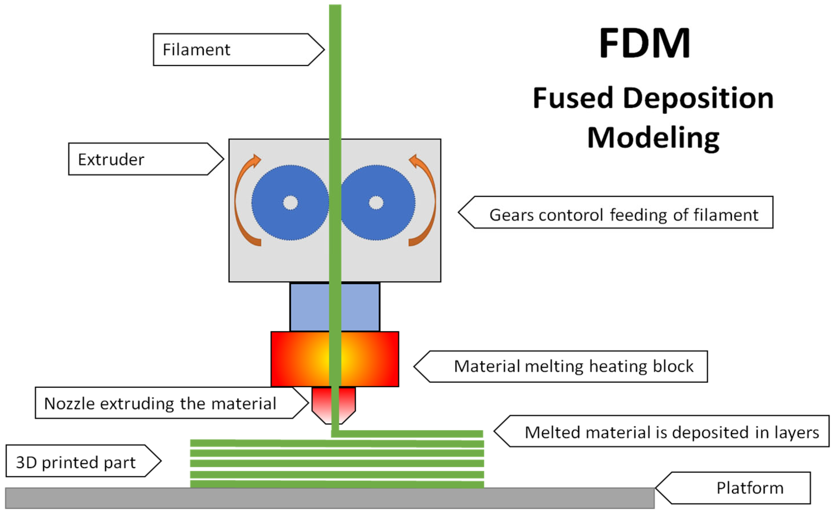
This study explores the potential of directly introducing dyes or chemical compounds to the polymer matrix during printing introducing. A diagram of the conventional FDM additive technology is depicted in Figure 2.
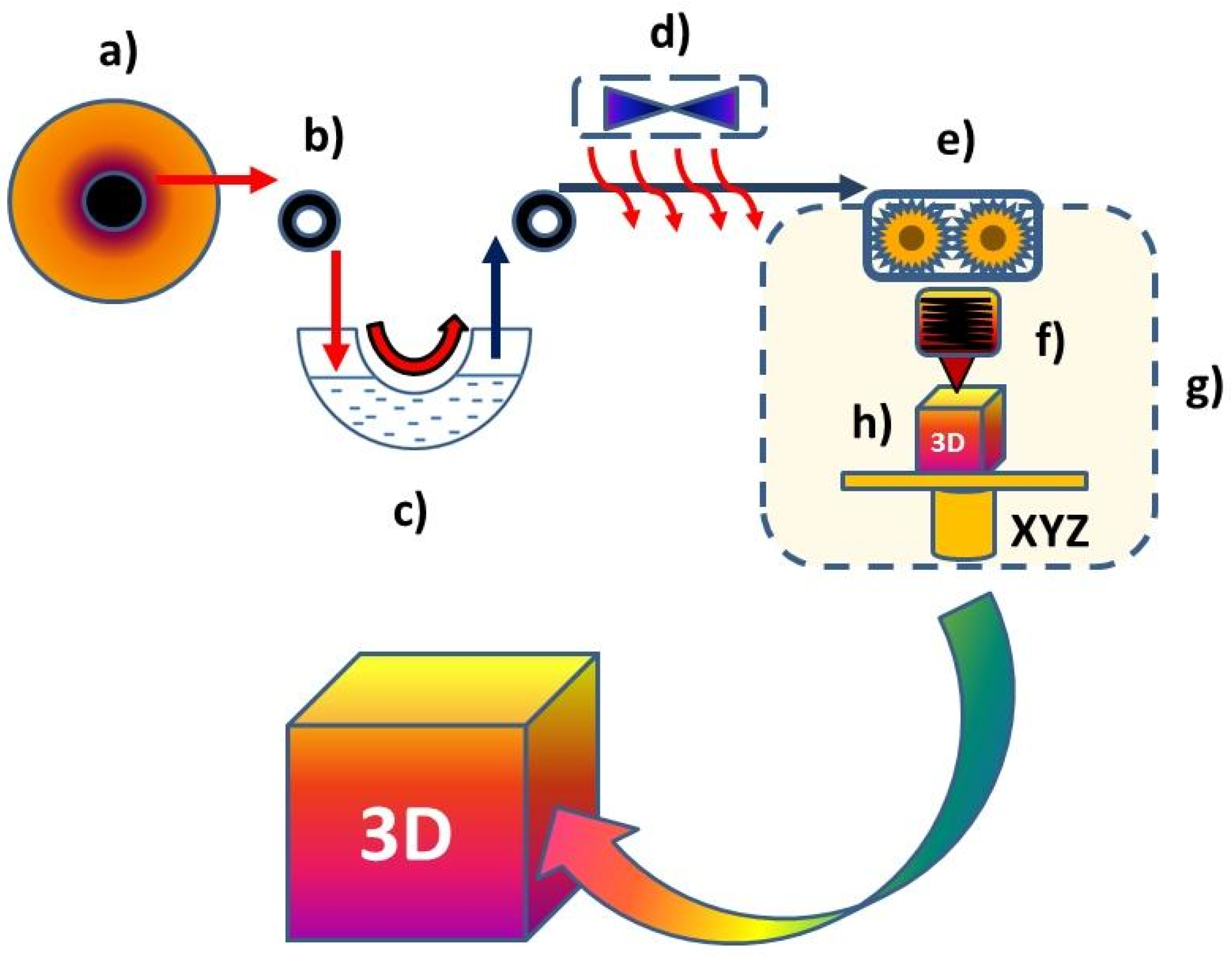
This research is based on using a 3D printer as a laboratory tool to introduce various chemical substances, e.g., dyes, solvents, organic compounds, and organosilicon compounds, into a polymer matrix. Most studies on polymer modification rely on traditional techniques that involve adding additives during the liquid polymer state. These methods include extrusion, mixing, rolling, and kneading in mixers [16] or mixing the modifier with a polymer solution in a volatile solvent and the subsequent removal [8]. This article discusses methods that eliminate the need for costly and energy-consuming processing equipment. These methods can be utilized in any laboratory by users without access to specialized devices. The proposed method of introducing chemical substances into the polymer matrix consists of surface modification of the filament through immersing in a solution (see Figure 3).
The filament is passed through a reservoir containing a modifier (a liquid chemical substance or its solution) and then through a drying or excess substance removal system. During the next stage, the filament that has been coated with the modifier is fed directly to the 3D printer head. Once there, it is melted and extruded through a nozzle, forming a three-dimensional object layer by layer. This method enables the testing of a large number of substances with high efficiency and throughput for creating previously unknown functional materials that open up entirely new application possibilities. Currently, tens of millions of different chemical compounds are discovered worldwide, and the properties and potential uses/applications of most of them have not yet been explored. Most additives introduced into the polymer matrix serve functional purposes, such as improving product durability under different atmospheric conditions or enhancing antistatic properties, increasing the strength and usability, changing the thermal properties, and modifying the color, among others [17,18,19,20].
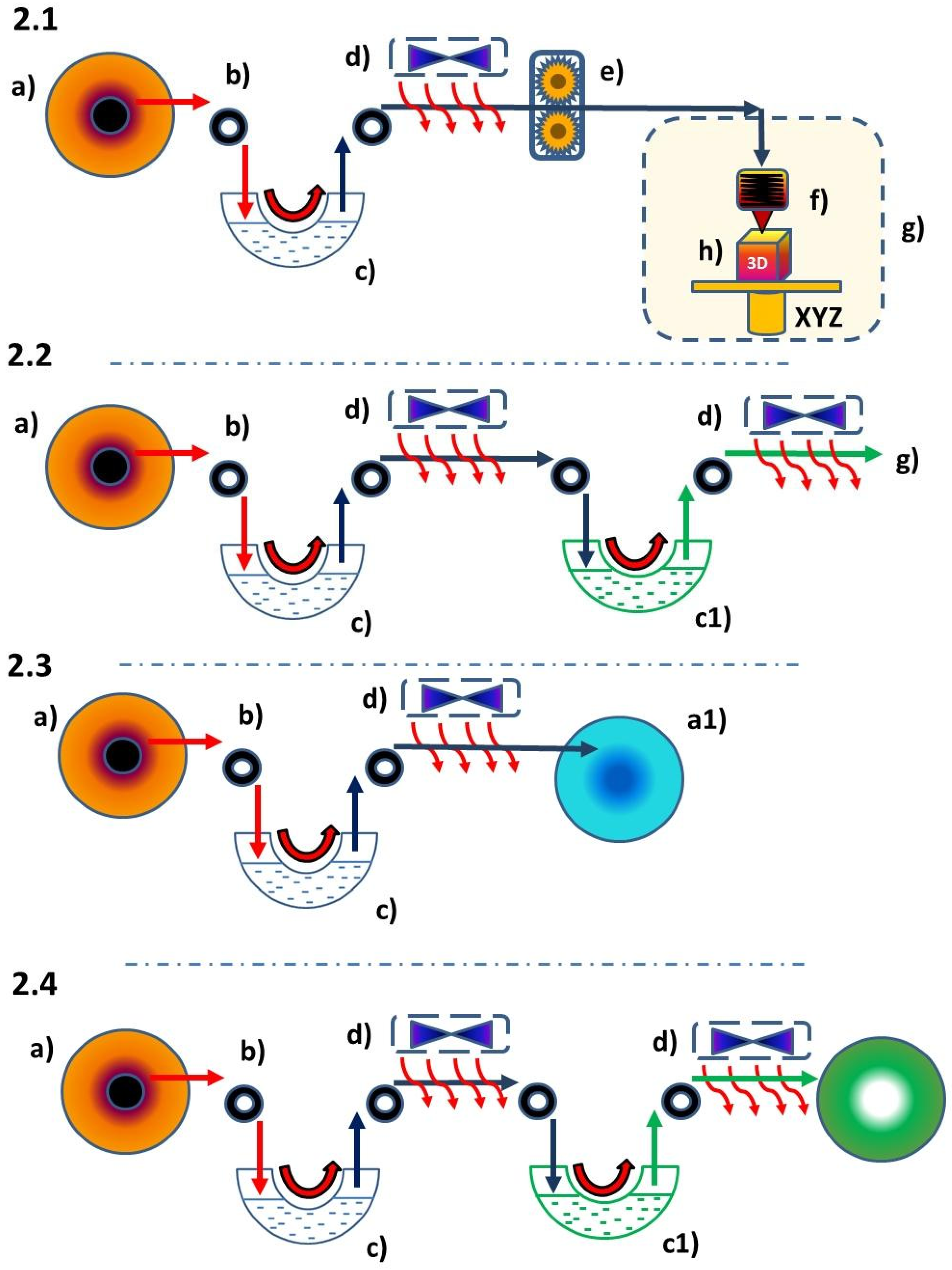
Coating a filament’s surface with a liquid modifier can occur either during printing (Figure 4(2.1,2.2)) or separately outside the printing process (Figure 4(2.3,2.4)). The L-FDM printing technique enables the use of one reservoir with a liquid modifier (Figure 4(2.1)) or multiple reservoirs with different chemical substances capable of dissolving in various solvents (Figure 4(2.2)). The filament modification presented in the diagrams in Figure 4(2.3,2.4) also involves passing the filament through a reservoir containing a modifier and a drying system, with the difference that, in the next stage, it does not go directly to the print head but is rewound onto the spool. This method also allows for multiple coatings of the filament surface with a chemical substance or the use of several different substances that dissolve in different solvents by winding the modified filament back onto the spool and passing it through the system again (Figure 4(2.3)) or by using multiple reservoirs with different modifiers (Figure 4(2.4)). This feature enables the filament to be utilized at a different location or time than the modification procedure itself.
In this article, we demonstrate the feasibility of incorporating particular substances into the polymer matrix during the printing process through the use of L-FDM technology. The obtained modifications were validated by a colorimetric analysis, optical microscopy, and scanning electron microscopy with energy-dispersive X-ray spectroscopy (SEM/EDS).

2. Materials and Methods

2.1. Materials

2.1.1. Polymers

Polylactide (PLA) pellets type Ingeo 2003D was purchased from NatureWorks (Minnetonka, MN, USA) and extruded into the filament, and polyethylene terephthalate glycol (PET-G) pellets type Select BD 110 was purchased from Selenis (Portalegre, Portugal) and extruded into the filament. PLA WOOD filament was purchased from Spectrum Filaments, WOODFILL filament from ColorFabb (Belfeld, The Netherlands), and acrylonitrile butadiene styrene (ABS+) filament and acrylonitrile styrene acrylate (ASA) filament from Devil Design (Mikołów, Poland).

2.1.2. Solvents and Liquid Chemicals

The chemicals were purchased from the following source: methanol (Me), isopropanol (iPr), and glycerine (GLY) p.a. were from P.P.H Stanlab (Lublin, Poland).

2.1.3. Solid Chemicals

The solid chemicals were purchased from the following source: silver nitrate, iron (III) chloride, lead acetate, and rubidium sulphate were from Merck (Darmstadt, Germany).

2.1.4. Dyes and Pigments

The dyes and pigments were purchased from the following sources: rhodamine B from Warchem (Warszawa, Poland); alkaline blue, methylene blue, methyl orange, eosin, fluorexone from Merck; transparent dye from Ag-Bet (Drzewoszki Wielkie, Poland); fabric dye from Biel i Kolor (Gieczno, Poland); transparent red dye from Moldoo; and printer ink 545 Black PIXMA 545 from CANON (Tokyo, Japan).

2.2. Devices and Methods

Test samples were obtained using the L-FDM method described in Section 1.2. Three printer models were used:
(1)
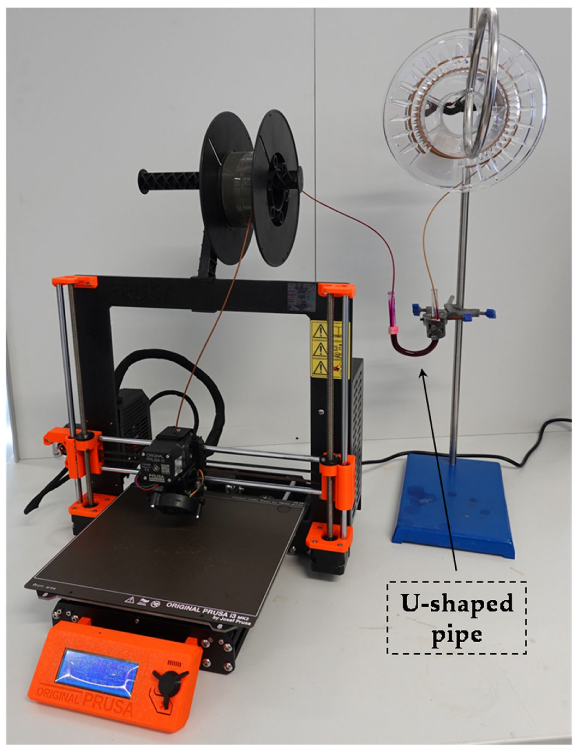
For printing brittle materials, as well as materials with high flexibility, i.e., PLA WOOD, WOODFILL, a TPU Original Prusa i3MK3S+ from Prusa Research a.s. was used. A printer with a direct extruder was used (Figure 5).
(2)
For printing samples from materials with high thermal shrinkage, i.e., ABS and ASA, a printer with a thermal chamber FlashForge Guider IIS (from FlashForge) (ABS, ASA) was used.
(3)
PLA and PET-G filaments were printed on Creality Ender 5 (Creality 3D) with a Bowden extruder. Table 1 presents the printing parameters.
Two types of 3D models were printed: bars (i.e., cubes of dimensions of 4 mm by 10 mm by 80 mm) and cylinders with a diameter of 20 cm. Detailed technical specifications of the printers used are included in the Supplementary Materials.
Figure 5. Photo of the idea of the L-FDM printing system. An example using a Prusa i3 MK3S+ 3D printer and a solution of rhodamine B.
Applsci 13 07393 g005

2.3. Analyses—Instrumental Methods and Measurements

Colorimetric measurements were performed using an EnviSense NR60CP colorimeter for the L*a*b* parameters (also referred to as CIELab). The diameter of the conical cap was 4 mm, and the detector was a silicon photodiode.
The morphology and microstructure of the prepared composites were observed by scanning electron microscopy (SEM). The imaging was performed in three SE modes. The surface observations were analyzed using a Hitachi SU70 scanning electron microscope equipped with an energy-dispersive spectrometer (EDS) for the chemical analysis.
Light microscopy images of the surface and fractures of the composites were taken using a KEYENCE VHX-7000 digital microscope (Keyence International, Mechelen, Belgium, NV/SA) with a VH-Z100R wide-angle zoom lens at 100× magnification. The images were taken with a depth composition and the aid of 3D imaging built-in software (System Ver. 1.05).

3. Results and Discussion

3.1. Colour

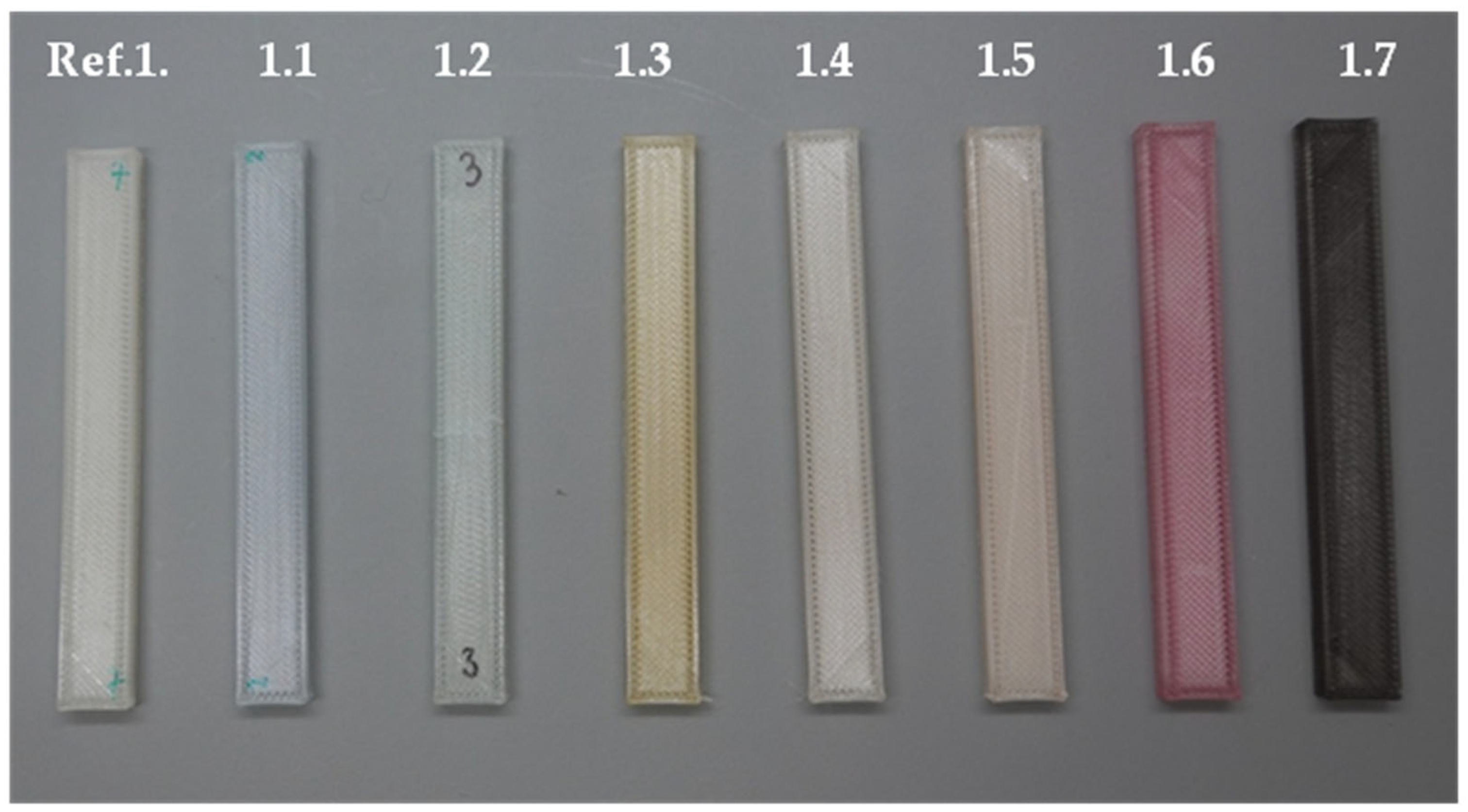
According to the research conducted, L-FDM technology enables the incorporation of coloring substances and elements. The feasibility of dyeing the filament during the printing process was investigated, using commercially available dyes such as rhodamine B, alkali blue, methylene blue, methyl orange, eosin, fluorenone, transparent red dye from Moldoo, and black printer ink from Canon (as shown in Figure 6, Figure 7, Figure 8 and Figure 9 and listed in Table 2). Initially, bar-shaped objects were printed, and then, a colorimetric and microscopic analysis was conducted to evaluate their characteristics. Further analysis was performed on the bars printed using L-FDM technology, utilizing a colorimeter and optical microscope for the structural analysis.
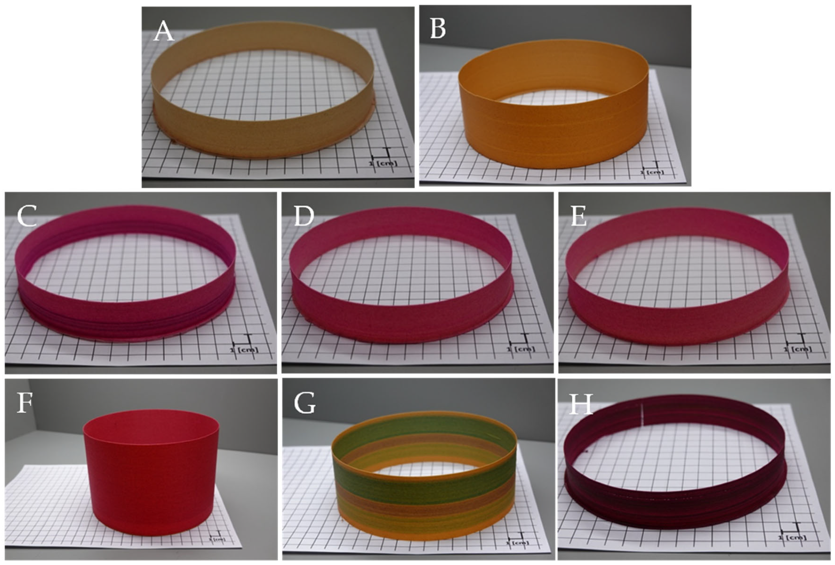
To accurately examine the color intensity of L-FDM composites, we printed cylinder-shaped objects. The design of these objects (shape and structure) allows for the observation of color spread in a single layer. For this experiment, we used PLA, as it is a transparent polymer with favorable processing parameters and minimal thermal shrinkage. Table 3 provides a summary of the assay.
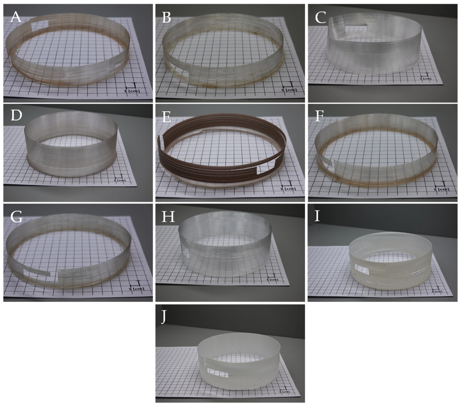
The L-FDM method of modification has been researched extensively, and other commonly used filaments have been tested. PET-G, which is more durable and flexible than PLA, was chosen for testing, as well as the ABS copolymer, which has a higher degree of flexibility and an opaque, matte surface. Both materials exhibit higher thermal shrinkage and require additional bed heating during the printing process. The filament dyeing process for these materials was similar to that used for PLA-based composites. Figure 8 illustrates the results obtained, and Table 4 provides a list of the symbols and sample names.
We created cylindrical PLA-based composite samples that incorporated fibers and wood dust as a filler, resulting in a porous structure and high absorbency. Our goal was to assess the efficacy of L-FDM technology modifications using a polymer with increased porosity and higher absorptivity compared to unmodified PLA. To conduct our research, we utilized various organic solvents and their mixtures containing a solution of rhodamine B. Figure 9 provides details on the dyes employed during the process, while Table 5 summarizes the sample compositions.

3.2. Elements

The L-FDM technique allows for the direct introduction of metal ions and nanoparticles into the polymer matrix during the 3D printing process. Metal salts are dissolved in organic solvents such as methanol or a solvent mixture. These selected compounds serve as both the source of the element and the determinant of the final product’s color, which is derived from the metal dispersed in the polymer matrix. To examine the distribution of ions within the polymer matrix, we utilized molecular structures and conducted SEM microscopy with EDS mapping (Section 3.5). The results confirm that this innovative printing technique is an effective way to incorporate modifiers into the polymer matrix (Figure 10). Table 6 shows the polymers used together with solutions of metal salts.
The same process was applied to PLA filaments that had dust and wood fibers added as a filler. It was anticipated that using a more absorbent and porous material would result in components with a more vivid color, such as when dyes are absorbed by the filament. Figure 11 shows the described effect is presented below, while the composition of the compositions obtained in the tests is presented in Table 7.

3.3. Colorimetric Analysis

Color change tests on samples using a colorimeter based on the CIELab system were conducted. The L*, a*, and b* represent each of the three values the CIELab color space uses to measure objective colors and calculate color differences [21]. The a and b axes are placed at right angles to each other and indicate the color tone. Parameter a* ranges from green (negative values) to red (positive values). In contrast, negative b* represents blue, and positive b* corresponds with yellow. The L parameter denotes luminance (brightness) and describes the color in the range from black to white. A negative value indicates a change to a darker shade, while a positive value means a change to a lighter shade. For black, its value is 0, while, for white, it is equal to 100. Using the CIELab system, differences between the color shades are determined. It is the distance between two points in a three-dimensional space, which can be written as [22]:
Δ E = Δ L 2 + Δ a 2 + Δ b 2
Δ L = L 2 + L 1
Δ a = a 2 + a 1
Δ b = b 2 + b 1
The assessment of the color change is made on the basis of the change of the ΔE parameter, the ranges of which are listed in Table 8.
Figure 12a shows the color changes (ΔE) of samples printed with the L-FDM method, in which dye solutions were used as modifiers, i.e., alkaline blue, methylene blue, methyl orange, eosin, fluorexone, transparent red dye by Moldoo, and black printer ink by Canon. The values on the Z-axis corresponded to the markings of the tested samples. The filaments were passed through a reservoir containing solutions of said dyes in methanol and printed in the form of trabeculae. The names and compositions of individual compositions were collected and presented earlier in Table 2. Figure 12b shows the color changes for cylindrical samples modified with commercially available dyes and solutions of rhodamine B in a mixture of water and organic solvents (water:isopropanol and water:isopropanol:glycerine) (see Table 3 and Table 4 for a detailed explanation of the determinations). Figure 12c shows the ΔE values for composites containing fibers and wood dust with both color modifiers (5.1–5.3) and metal salts (6.1–6.3, sample designations Table 5 and Table 7). Figure 12d shows color changes for the composites based on PLA and PET-G modified with metal salts (silver nitrate and iron III chloride) (Table 6).
Among the tested PLA composites (Figure 12a), the least intense coloration was observed for samples modified with a methanol solution of eosin and fluorexon (samples marked 1.4 and 1.5), while the most intense coloration and the highest value of delta E showed samples marked 1.6 and 1.7. Differences in the degree of coloring resulted from the compatibility of a given dye with the polymer matrix, its solubility in the solvent, and the molar absorption coefficient, which is characteristic of a given dye structure. In the case of the cylindrical samples (Figure 12b), the analysis of the color changes showed that, for the PLA polymer, the highest changes were characterized by 2.2, 2.7, and 2.10, which were water:isopropanol solutions in a 1:1 ratio. The analysis of the collected data indicated that the factor determining the degree of saturation of the material with the dye solution was the solvent. The collected data for the rhodamine solutions indicated ΔE = 5.83 for sample 2.6, in which the solvent was water, ΔE = 63.04 for sample 2.7 in a H2O:iPr 1:1 solution, and ΔE = 24.71 in H2O:iPr:Gly 1:1:1 (sample 2.8); the obtained results indicated that the water:alcohol solution penetrated the pores of the material, enabling its better penetration and more intense coloring, and the addition of glycerin increased the density and viscosity of the solution. Therefore, its ability to penetrate the composite structure decreased, the wettability of the polymer with water was limited compared to other solutions, and the smallest color change was observed between the reference and the modified sample. Analogous tests were carried out for rhodamine saturated solutions in water, H2O:iPr 1:1, and H2O:iPr:Gly 1:1:1 (samples 2.9, 2.10, and 2.11, respectively). The smallest color change ΔE < 3.5 was observed for samples 2.3 and 2.4 (commercial dyes). Colorimetric tests carried out for composites based on PET-G modified with various rhodamine solutions showed an analogous effect, as for PLA. The ΔE for PET-G dyed with rhodamine B solution in H2O:iPr 1:1 was 124.97 (No. 3.1), and the ΔE of rhodamine in H2O:iPr:Gly was 62.66 (No. 3.5). PET-G was characterized by a higher saturation of the modifier compared to PLA. Dyes such as navy blue fabric dye (sample 3.7) and transparent yellow dye (sample 3.6) were the least effectively introduced into the polymer matrix (ΔE 3.82 and 0.92, respectively). The ABS polymer was characterized by an intense color change after the printing process, with green dye and rhodamine B solutions compared to transparent PLA and PET-G (samples 4.1 and 4.2). The ΔE for the samples of PLA WOODFILL and WOOD composites samples (Figure 12c) reached high values (above 11). These composites had a porous structure due to the presence of a filler in the form of fibers and wood dust. The result was a better ability to absorb solutions with liquid dyes and modifiers into the material, thanks to which, the L-FDM prints were characterized by an increased content of dye in the polymer matrix and, thus, more intense coloring. Modification of the polymers was also carried out in the presence of solutions containing metal salts, which could be used to introduce specific elements into the polymer matrix and, thanks to the molecular structure, significantly simplify the method of confirming the ongoing modification using microscopic methods and, additionally, intensively stain the material. Cylinders modified with silver nitrate and iron (III) chloride were characterized by ΔE > 5, which indicated a high saturation with ions both on the surface and in the internal structure of the polymer (Section 3.4 and Section 3.5). The color change analysis carried out confirmed the effective introduction of dyes and chemical compounds into the polymer matrix. The saturation and, thus, the intensity of the color depended on the solvents used, the concentration, and the microstructure of the polymer surface.

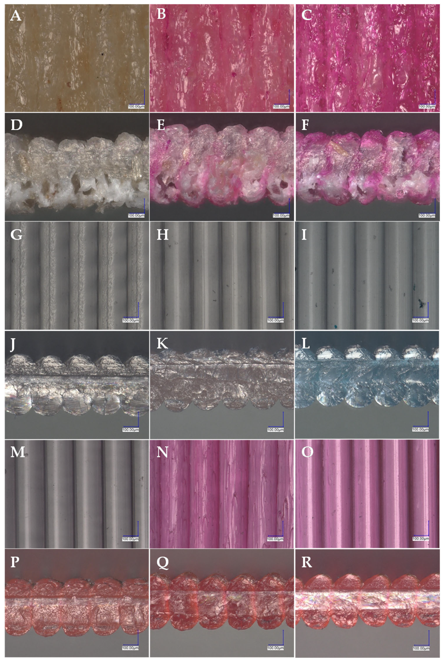
3.4. Microscopic Analysis

Figure 13 and Figure 14 show the surfaces and sections of the cylinder-shaped samples obtained by L-FDM. Filaments based on PLA and PLA with a wood filler were passed through a container containing a dye solution: rhodamine B in various organic solutions, navy blue fabric dye, and transparent blue turquoise dye are presented in Figure 13 and PLA, PLA WOOD, and PET-G after passing through solutions containing metal salts (Figure 14). Iron (III) chloride and silver nitrate were used as dyes and element sources because of their distinctive colors. All samples were printed in the vase mode, which means that the cylinder wall had a width similar to the diameter of the nozzle and was made of one layer. It was decided to choose such a model object so that the observation of the color change was as beneficial as possible, and the effect was not multiplied by thicker walls of the printouts. In the cross-sectional images, only the outline was visible, with no fill. Pictures of the surfaces of the dyed cylinders collected in Figure 13 and Figure 14 allow assessing the intensity of the color and the uniformity of the dye distribution in the polymer structure for each of the layers arranged on top of each other. Based on the analyses carried out, it was observed that the cylinder models showed a constant level of color intensity throughout the volume. Although slight agglomerations of the dye particles were observed in the microscopic images, their distribution on all layers of the printed model seemed to be even. The cross-sectional images proved that the dye not only covered the surface of the print but also penetrated deep into the polymer structure, which confirmed the conclusions formulated for the colorimetric measurements. In the case of using a polymer filled with fiber and wood flour (PLA WOOD and WOODFILL), more strongly colored areas could be observed in the microscopic images, which was evidenced by the greater color intensity (the presence of darker spots) (Figure 14N,O). This effect can be attributed to the greater absorption of the dye solution by the porous filler. Figure 13E,F show the WOODFILL fiber dyed with rhodamine B solutions. The cross-section of the print layer showed stronger coloring on its outer edge and at the interface of individual layers. The intensity of the color depended on both the type of solvent used and the amount of dissolved dye.

3.5. EDS Analysis—Elements Mapping

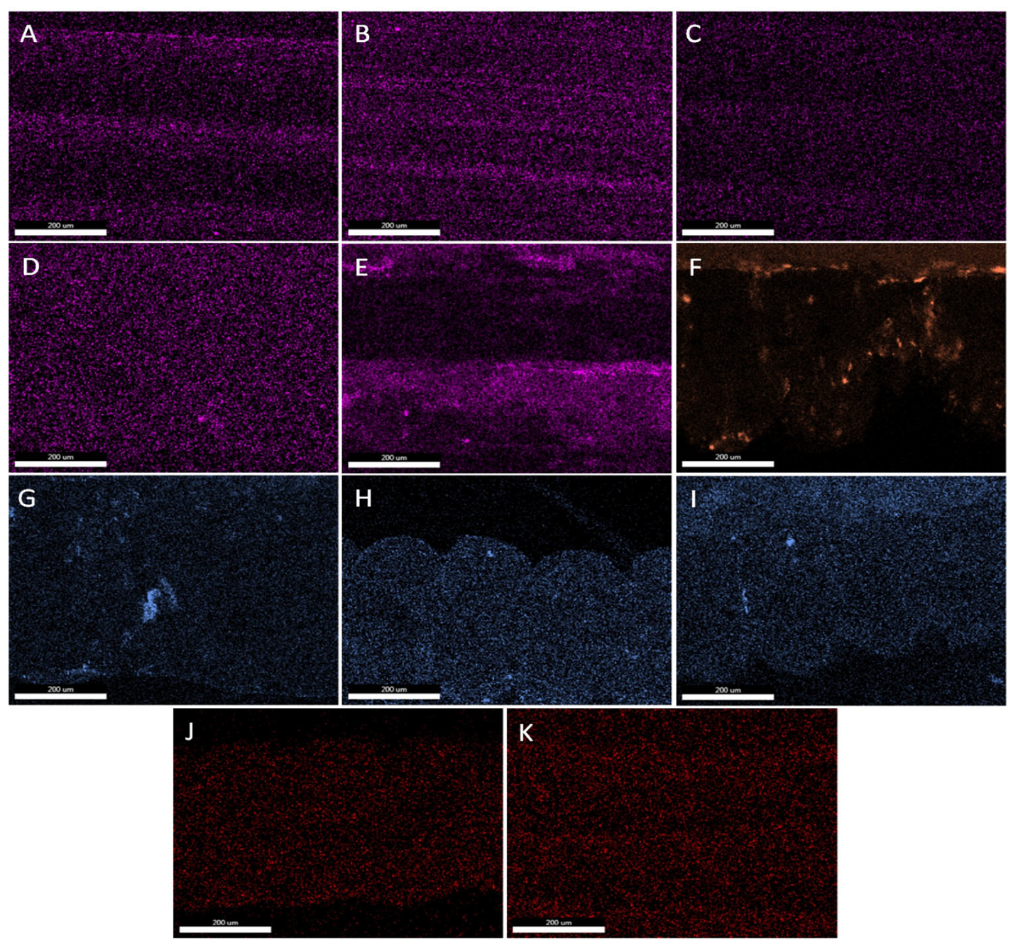
The EDS mapping of the surfaces and cross-sections of L-FDM-printed cylinders (Figure 15) illustrated the distribution of the elements introduced with the L-FDM technique in the polymer matrix. The surfaces of the cylinder walls of the samples printed from polymers and copolymers such as ABS, ASA, PLA, and PET-G were characterized by a uniform distribution of the elements in the matrix (Figure 15A–C,E). On the other hand, in the cross-section of the printing layer (see also Figure S1 in the Supplementary Materials), a higher content of lead was visible on its outer edge and at the contact point of the individual layers. The distribution of iron and rubidium in the EDS images of unfilled fiber samples was more homogeneous (Figure 15H,I,J). The large clusters visible in the EDS images of the PLA WOOD prints with silver nitrate and ferric chloride were probably the result of increased absorption of the modifier solution by the porous filler, which consisted of wood fibers and dust. When comparing the EDS images of the L-FDM prints with lead acetate dissolved in methanol (saturated solution), differences in the lead dispersion could be observed. Based on this, it could be concluded that, with the printing parameters used, the material from which the filament was made had either a better or worse ability to mix with the modifier used. This dependence was visibly better on the EDS images of the cylinder cross-sections (Figure 15A and Supplementary Figure S1A–C). As could be seen, the ASA polymer showed the lowest ability to penetrate the polymer matrix, while ABS and PLA WOOD showed the highest concentration of lead on the outer edges and at the interface of the individual layers. PET-G exhibited the most homogeneous lead dispersion in the polymer matrix using the L-FDM technique with lead acetate dissolved in methanol. The color intensity on the EDS maps was higher for the PLA WOOD polymer. This effect occurred due to better wetting of the filament surface (rough structure of the filament surface) and its greater absorbency caused by the presence of wood fibers and dust. The EDS analysis provided evidence of elements in the polymer matrix of the L-FDM prints. This finding confirmed the possibility of using this technique as a tool for introducing various chemical substances into the polymer matrix.

3.6. Functional Features, Limitations, and Directions of Potential Applications for the L-FDM Method

The examples displayed in Table 9 demonstrated the diverse applications of the innovative L-FDM printing technique. In the pharmaceutical area, L-FDM printing allows producing personalized drugs, allowing the adjustment of doses and compositions tailored to the individual needs of patients. In addition, this technology enables the production of tablets of nonstandard shapes with the possibility of controlled release [23,24,25].
Three-dimensional printing presents a potential avenue for incorporating radioactive isotopes into polymer matrices in the realm of isotope technologies. With this method, the precision and customization are enhanced, allowing for the creation of printed targets that optimize the geometry. This ultimately enhances the irradiation efficiency and overall effectiveness. In the field of nuclear medicine, 3D printing is used to create personalized, anthropomorphic phantoms. These phantoms are important for planning radiotherapy, validating dosimetry, and studying medical imaging. Tailored treatment strategies for patients can be achieved through the use of custom phantoms, resulting in improved outcomes. L-FDM technology allows for the direct production of radioactive materials without the need for additional processing steps such as rolling, extrusion, or granulation. By eliminating these steps, the risk of contamination for various machines is greatly reduced [26,27,28]. One crucial matter to consider is the incorporation of technology in basic chemical research. Utilizing new compounds can expedite the testing process for potential applications without requiring scientists to possess in-depth knowledge regarding plastic processing or complex equipment. The modification of a polymer with chemical compounds can be studied with ease by researchers immediately after laboratory synthesis. Apart from medicine and pharmacy, 3D printing has potential applications in the cosmetic industry. Specifically, this technique can help in printing skin delivery platforms such as patches and microneedles [29]. Printed cosmetic microneedles can be a delivery system for both hydrophilic and lipophilic active ingredients that will be introduced into the material during the L-FDM process [30]. According to scientific research, the use of 3D printing allows for the customization of dressings to fit the specific needs of each patient. By incorporating metals, nanoparticles, drugs, natural compounds, proteins, and peptides into the polymer matrix, there is the potential for these dressings to aid in wound healing, acne treatment, pain relief, and antiaging [31].
In addition, the 3D printing method holds potential in the field of oceanography. With the harmful impact of ocean acidification on coral reef ecosystems, alkaline materials may be incorporated into 3D-printed objects to aid in the production of artificial coral replicas for reef restoration. The integration of nanotechnologies can aid in the creation of 3D-printed replicas of coral reefs that will promote a faster recovery. The printed replicas can incorporate slow-release materials that maintain an alkaline pH into the surrounding microenvironment, while soluble materials can be used to create nano/micropores that resemble natural porous corals. This facilitates rapid growth and enables live corals to penetrate the structures [32]. Artificial coral structures can be designed to provide a variety of microhabitats for different species of corals and other marine life.
The use of 3D printing in chemical engineering has proven to be highly valuable, particularly in the development of structural catalysts, mixers, and reactors. Through the use of 3D printing, complex and customized structures can be created, ultimately leading to an improved process efficiency and better results in a variety of chemical engineering applications [33]. A novel printing technology, capable of incorporating modifiers into polymer matrices, holds promise for advancement in materials engineering. Using the L-FDM method, scientists can use this as a tool for efficient, cheaper, and quick production of samples for research purposes and for imparting new properties to polymeric materials [34,35].
The L-FDM technique holds significant potential in the field of bioengineering, particularly in the areas of implants, tissue engineering, and regenerative medicine. The primary focus of tissue engineering lies in designing and producing scaffolds with specific properties, which can be achieved through the application of L-FDM. With the new method, it is possible to introduce ions found in the body’s natural environment, resulting in biocompatible materials [36,37]. The use of agrochemicals with controlled-release systems is beneficial, as it enables the maximum effectiveness while minimizing nonspecific side effects. Moreover, it reduces the negative impact on the environment, human health, and other organisms. There are different ways to release substances, such as microcapsules, nanoparticles, delayed-release formulations, and polymer matrices. Using the L-FDM method, materials can be designed to have active ingredients that enable a controlled release by responding to factors such as humidity, temperature, and pH [38,39,40]. Currently, the known technologies on the market indicate the possibility of in situ thermal formation of nanoparticles (e.g., silver nanoparticles) during filament extrusion. The use of the L-FDM method allows the omission of several processing processes, such as the homogenization of materials, granulation, and extrusion, because it is possible to obtain nanoparticles from chemical precursors as a result of thermal decomposition directly during printing [41,42]. The aforementioned examples are just a glimpse of the vast application possibilities of the innovative L-FDM printing technique. Its potential and significant contributions to the field of science make it imperative to be explored and developed further.
During the research, problems were encountered during the L-FDM printing process; it was also noticed that it has some limitations, but some of them can be overcome/circumvented by using solutions, examples of which are listed in Table 10. The first problem is the relatively small amount of modifier possible to be introduced into the polymer, and another problem is with the precise determination of its contents. The proposed solution to the above-mentioned problems is, for example, increasing the total surface of the polymer absorbing the modifier by reducing the diameter of the filament, increasing the porosity, or changing the material from which the filament is made. The amount of the introduced substance can be controlled by a quantitative analysis of the finished product or inline spectroscopic measurements performed during the printing process with the use of colored substances. Another challenge posed by L-FDM printing is the appropriate selection of solvents for the material from which the filament is made and the chemical substance from which we want to make the solution. If there is a problem with the dissolution of the polymer in an organic solvent, the solvent or polymer from which the filament is made should be changed. Another solution to the problem of dissolving the filament is to control the temperature of the solvent in such a way that only the introduced chemical substance is dissolved. During the L-FDM printing process, to maintain the homogeneity of the obtained 3D elements (uniform color or even introduction of the modifier into the polymer matrix), it is important to evenly cover the surface of the filament with the solution. For this purpose, in addition to the appropriate selection of the polymer and solvent, the addition of a surfactant can be used. Depending on the viscosity of the modifier solution, the filament is covered with a thicker or thinner layer after immersion. The filament is covered with a thicker layer of the modifier solution if it has a higher viscosity.
The amount of absorbed solution from the reservoir by the polymer depends, among other factors, on the duration of its interaction with the filament. This time is influenced by the desired printing speed, which is the rate at which the material is fed.

4. Conclusions

This paper presents an innovative direct method of introducing chemical substances such as dyes or chemical compounds into printouts in the FDM technique. Colorimetric tests (CIELab) and microscopic tests with EDS mapping confirm that plastics are modified directly during printing. The proposed approach described in this paper omits the use of complicated methods and expensive processing equipment and may potentially be a tool for obtaining materials with special applications. The research described is a small part of the technical possibilities for this technique. The proposed technique simplifies the preparation of new materials using thermoplastic polymers. The described solution makes it possible to expand the fields of application of the classic FDM printing technology, opening up new procedures and processes for research laboratories in the fields of chemistry, pharmacy, biotechnology, engineering, and many others. We propose to use the name liquid for fused deposition modeling (L-FDM) for the described technique. The authors of this work will continue research on the application of the developed method for the direct modification of filaments in the printing process.

5. Patents

The results of this publication have been patented with Polish patent application no. P.441923.

Supplementary Materials

The following supporting information can be downloaded at: https://www.mdpi.com/article/10.3390/app13137393/s1: Video S1: Process of liquid for fused deposition modeling; Table S1: FDM 3D printers used in this study—technical parameters; Table S2: FDM 3D printers used in this study—printing parameters.; Figure S1: EDS images of LFDM printed parts with metal ions introduced into the polymer matrix.; Figure S2: EDS images of LFDM printed parts with metal ions introduced into the polymer matrix. Images of the surface of the cylinder’s side.; Figure S3: EDS images of LFDM printed parts with metal ions introduced into the polymer matrix. Images of the cross-sections.

Author Contributions

Conceptualization, R.E.P. methodology, R.E.P.; software, E.G., D.P. and B.S.; validation, R.E.P. and B.S.; formal analysis, R.E.P., E.G., D.P. and B.S.; investigation, R.E.P. and E.G. resources, R.E.P. and B.S.; data curation, R.E.P.; writing—original draft preparation; R.E.P., E.G., D.P. and B.S., writing—review and editing, R.E.P. and B.S.; visualization, R.E.P. and E.G.; supervision, R.E.P.; project administration, R.E.P. and B.S.; and funding acquisition, R.E.P. and B.S. All authors have read and agreed to the published version of the manuscript.

Funding

Part of this research was funded by the National Centre for Research and Development, Poland, grant no. LIDER/01/0001/L-10/18/NCBR/2019, and by resources from Adam Mickiewicz University (Poland).

Institutional Review Board Statement

Not applicable.

Informed Consent Statement

Not applicable.

Data Availability Statement

Not applicable.

Conflicts of Interest

The authors declare no conflict of interest.

References

  1. Guo, N.; Ming-Chuan, L. Additive Manufacturing: Technology, Applications and Research Needs. Front. Mech. Eng. 2013, 8, 215–243. [Google Scholar] [CrossRef]
  2. Samykano, M. Mechanical Property and Prediction Model for FDM-3D Printed Polylactic Acid (PLA). Arab. J. Sci. Eng. 2021, 46, 7875–7892. [Google Scholar] [CrossRef]
  3. Wang, J.; Goyanes, A.; Gaisford, S.; Basit, A.W. Stereolithographic (SLA) 3D Printing of Oral Modified-Release Dosage Forms. Int. J. Pharm. 2016, 503, 207–212. [Google Scholar] [CrossRef]
  4. Peng, C.; Tran, P. Bioinspired Functionally Graded Gyroid Sandwich Panel Subjected to Impulsive Loadings. Compos. Part B Eng. 2020, 188, 107773. [Google Scholar] [CrossRef]
  5. Ramya, A.; Vanapalli, S. 3D Printing Technologies in Various Applications. IJMET 2016, 7, 396–409. [Google Scholar]
  6. Shahrubudin, N.; Lee, T.C.; Ramlan, R. An Overview on 3D Printing Technology: Technological, Materials, and Applications. Procedia Manuf. 2019, 35, 1286–1296. [Google Scholar] [CrossRef]
  7. Tran, T.Q.; Ng, F.L.; Kai, J.T.Y.; Feih, S.; Nai, M.L.S. Tensile Strength Enhancement of Fused Filament Fabrication Printed Parts: A Review of Process Improvement Approaches and Respective Impact. Addit. Manuf. 2022, 54, 102724. [Google Scholar] [CrossRef]
  8. Saggiomo, V. A 3D Printer in the Lab: Not Only a Toy. Adv. Sci. 2022, 9, 2202610. [Google Scholar] [CrossRef]
  9. Salentijn, G.I.; Oomen, P.E.; Grajewski, M.; Verpoorte, E. Fused Deposition Modeling 3D Printing for (Bio)analytical Device Fabrication: Procedures, Materials, and Applications. Anal. Chem. 2017, 89, 7053–7061. [Google Scholar] [CrossRef] [Green Version]
  10. Capel, A.J.; Rimington, R.P.; Lewis, M.P.; Christie, S.D.R. 3D Printing for Chemical, Pharmaceutical and Biological Applications. Nat. Rev. Chem. 2018, 2, 422–436. [Google Scholar] [CrossRef] [Green Version]
  11. Mani, M.P.; Sadia, M.; Jaganathan, S.K.; Khudzari, A.Z.; Supriyanto, E.; Saidin, S.; Ramakrishna, S.; Ismail, A.F.; Faudzi, A.A.M. A Review on 3D Printing in Tissue Engineering Applications. J. Polym. Eng. 2022, 42, 243–265. [Google Scholar] [CrossRef]
  12. Waheed, S.; Cabot, J.M.; Macdonald, N.P.; Lewis, T.; Guijt, R.M.; Paull, B.; Breadmore, M.C. 3D Printed Microfluidic Devices: Enablers and Barriers. Lab Chip 2016, 16, 1993–2013. [Google Scholar] [CrossRef] [PubMed] [Green Version]
  13. Hou, W.; Bubliauskas, A.; Kitson, P.J.; Francoia, J.-P.; Powell-Davies, H.; Gutierrez, J.M.P.; Frei, P.; Manzano, J.S.; Cronin, L. Automatic Generation of 3D-Printed Reactionware for Chemical Synthesis Digitization using ChemSCAD. ACS Central Sci. 2021, 7, 212–218. [Google Scholar] [CrossRef] [PubMed]
  14. Sebai, A.; Łątka, M.; Gadomska-Gajadhur, A. Polilaktyd w Systemach Leków o Kontrolowanym Czasie Uwalniania i Inżynierii Tkankowej; Oficyna Wydawnicza Politechniki Wrocławskiej: Rzeszów, Poland, 2016; pp. 210–213. [Google Scholar]
  15. Hock, S.; Rein, C.; Rose, M. 3D-Printed Acidic Monolithic Catalysts for Liquid-Phase Catalysis with Enhanced Mass Transfer Properties. Chemcatchem 2022, 14, 202101947. [Google Scholar] [CrossRef]
  16. Henczykowski, M.; Oleksy, M. Technologia Przetwórstwa Tworzyw Sztucznych; Oficyna Wydawnicza Politechnika Rzeszowska: Rzeszów, Poland, 1999. [Google Scholar]
  17. Dizon, J.R.C.; Espera, A.H., Jr.; Chen, Q.; Advincula, R.C. Mechanical Characterization of 3D-Printed Polymers. Addit. Manuf. 2018, 20, 44–67. [Google Scholar] [CrossRef]
  18. Lee, C.S.; Kim, S.G.; Kim, H.J.; Ahn, S.H. Measurement of Anisotropic Compressive Strength of Rapid Prototyping Parts. J. Mater. Process. Technol. 2007, 187, 627–630. [Google Scholar] [CrossRef]
  19. Ryan, K.J.; Lupton, K.E.; Pape, P.G.; John, V.B. Ultra-high-molecular-weight functional siloxane additives in polymers. Effects on processing and properties. J. Vinyl Addit. Technol. 2020, 6, 7–19. [Google Scholar] [CrossRef]
  20. Abdilla, A.; D’Ambra, C.A.; Geng, Z.; Shin, J.J.; Czuczola, M.; Goldfred, D.J.; Biswas, S.; Mecca, J.M.; Sweir, S.; Bekemeier, T.D.; et al. Silicone Based Polymers Blends: Enhancing Properties Through Compatibilization. Polym. Sci. 2021, 59, 2114. [Google Scholar] [CrossRef]
  21. Ly, B.C.K.; Dyer, E.B.; Feig, J.L.; Chien, A.L.; Del Bino, S. Research Techniques Made Simple: Cutaneous Colorimetry: A Reliable Technique for Objective Skin Color Measurement. J. Investig. Dermatol. 2020, 140, 3–12.e1. [Google Scholar] [CrossRef] [Green Version]
  22. Luo, M.R. Encyclopedia of Color Science and Technology; Springer: New York, NY, USA, 2015; pp. 1–7. [Google Scholar]
  23. Prasad, L.K.; Smyth, H. 3D Printing Technologies for Drug Delivery: A review. Drug Dev. Ind. Pharm. 2015, 42, 1019–1031. [Google Scholar] [CrossRef]
  24. Jain, V.; Haider, N.; Jain, K. 3D Printing in Personalized Drug Delivery. Curr. Pharm. Des. 2019, 24, 5062–5071. [Google Scholar] [CrossRef] [PubMed]
  25. Beg, S.; Almalki, W.H.; Malik, A.; Farhan, M.; Aatif, M.; Rahman, Z.; Alruwaili, N.K.; Alrobaian, M.; Tarique, M.; Rahman, M. 3D Printing for Drug Delivery and Biomedical Applications. Drug Discov. Today 2020, 25, 1668–1681. [Google Scholar] [CrossRef] [PubMed]
  26. Gear, J.I.; Cummings, C.; Sullivan, J.; Cooper-Rayner, N.; Downs, P.; Murray, I.; Flux, G.D. Radioactive 3D Printing for the Production of Molecular Imaging Phantoms. Phys. Med. Biol. 2020, 65, 175019. [Google Scholar] [CrossRef] [PubMed]
  27. Tran-Gia, J.; Schlögl, S.; Lassmann, M. Design and Fabrication of Kidney Phantoms for Internal Radiation Dosimetry Using 3D Printing Technology. J. Nucl. Med. 2016, 57, 1998–2005. [Google Scholar] [CrossRef] [Green Version]
  28. Gear, J.I.; Cummings, C.; Craig, A.J.; Divoli, A.; Long, C.D.C.; Tapner, M.; Flux, G.D. Abdo-Man: A 3D-Printed Anthropomorphic Phantom for Validating Quantitative SIRT. EJNMMI Phys. 2016, 3, 17. [Google Scholar] [CrossRef] [Green Version]
  29. Jiao, Y.; Stevic, M.; Buanz, A.; Uddin, M.J.; Tamburic, S. Current and Prospective Applications of 3D Printing in Cosmetics: A Literature Review. Cosmetics 2022, 9, 115. [Google Scholar] [CrossRef]
  30. Islam, H.; Poly, T.S.; Tisha, Z.T.; Rahman, S.; Naveed, A.I.J.; Ahmed, A.; Ahmed, S.N.; Hassan, J.; Uddin, M.J.; Das, D.B. 3D Printed Hollow Microneedles for Treating Skin Wrinkles Using Different Anti-Wrinkle Agents: A Possible Futuristic Approach. Cosmetics 2023, 10, 41. [Google Scholar] [CrossRef]
  31. De Oliveira, R.S.; Fantaus, S.S.; Guillot, A.J.; Melero, A.; Beck, R.C.R. 3D-Printed Products for Topical Skin Applications: From Personalized Dressings to Drug Delivery. Pharmaceutics 2021, 13, 1946. [Google Scholar] [CrossRef]
  32. Mohammed, J.S. Applications of 3D Printing Technologies in Oceanography. Methods Oceanogr. 2016, 17, 97–117. [Google Scholar] [CrossRef]
  33. Parra-Cabrera, C.; Achille, C.; Ameloot, C. 3D Printing in Chemical Engineering and Catalytic Technology: Structured Catalysts, Mixers and Reactors. Chem. Soc. Rev. 2018, 47, 209–230. [Google Scholar] [CrossRef]
  34. Zhang, Z.P.; Rong, M.Z.; Zhang, M.Q. Polymer Engineering Based on Reversible Covalent Chemistry: A Promising Innovative Pathway Towards New Materials and New Functionalities. Prog. Polym. Sci. 2018, 80, 39–93. [Google Scholar] [CrossRef]
  35. Brząkalski, D.; Sztorch, B.; Frydrych, M.; Pakuła, D.; Dydek, K.; Kozera, R.; Boczkowska, A.; Marciniec, B.; Przekop, R.E. Limonene Derivative of Spherosilicate as a Polylactide Modifier for Applications in 3D Printing Technology. Molecules 2020, 25, 5882. [Google Scholar] [CrossRef] [PubMed]
  36. Konta, A.A.; García-Piña, M.; Serrano, D.R. Personalised 3D Printed Medicines: Which Techniques and Polymers Are More Successful? Bioengineering 2017, 4, 79. [Google Scholar] [CrossRef] [Green Version]
  37. Kalita, S. Rapid Prototyping in Biomedical Engineering: Structural Intricacies of Biological Materials. Biointegration of Medical Implant Materials; Woodhead Publishing: Cambridge, UK, 2010; pp. 349–397. [Google Scholar] [CrossRef]
  38. Vittal, L.V.M.; Rookes, J.; Ben Boyd, B.; Cahill, D. Analysis of Plant Cuticles and Their Interactions with Agrochemical Surfactants Using a 3D Printed Diffusion Chamber. Plant Methods 2023, 19, 37. [Google Scholar] [CrossRef] [PubMed]
  39. Roy, A.; Singh, S.K.; Bajpai, J.; Bajpai, A.K. Controlled pesticide release from biodegradable polymers. Open Chem. 2014, 12, 453–469. [Google Scholar] [CrossRef]
  40. Majeed, Z.; Ramli, N.K.; Mansor, N.; Man, Z. A comprehensive review on biodegradable polymers and their blends used in controlled-release fertilizer processes. Rev. Chem. Eng. 2015, 31, 69–95. [Google Scholar] [CrossRef]
  41. Podstawczyk, D.; Skrzypczak, D.; Połomska, X.; Stargała, A.; Witek-Krowiak, A.; Guiseppi-Elie, A.; Galewski, Z. Preparation of Antimicrobial 3D Printing Filament: In Situ Thermal Formation of Silver Nanoparticles During the Material Extrusion. Polym. Compos. 2020, 41, 4692–4705. [Google Scholar] [CrossRef]
  42. Xu, W.; Jambhulkar, S.; Zhu, Y.; Ravichandran, D.; Kakarla, M.; Vernon, B.; Lott, D.G.; Cornella, J.L.; Shefi, O.; Miquelard-Garnier, G.; et al. 3D Printing for Polymer/Particle-Based Processing: A Review. Compos. Part B Eng. 2021, 223, 109102. [Google Scholar] [CrossRef]
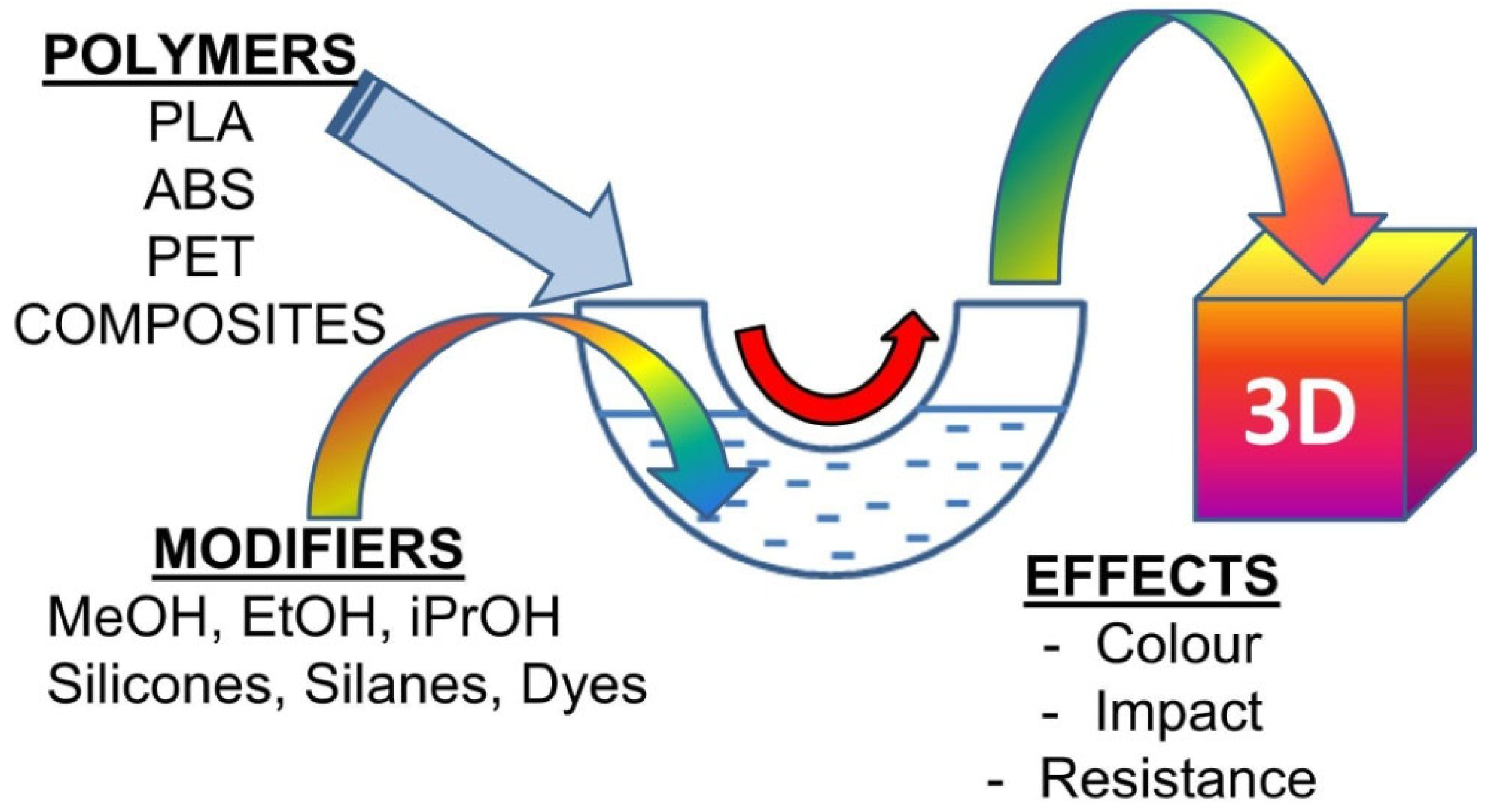
Figure 1. L-FDM printing technique obtaining samples for testing.
Applsci 13 07393 g001
Figure 2. A diagram of the 3D printing process using the FDM technique.
Applsci 13 07393 g002
Figure 3. A short concept of a new printing technique—liquid for fused deposition modeling (L-FDM): (a) polymer material spool, (b) a filament, (c) reservoir containing a modifier, (d) drying of the modified filament, and (g) traditional FDM printing ((e) extruder, (f) heating block with nozzle, (h) 3D-printed part)).
Applsci 13 07393 g003
Figure 4. Possible variants of the L-FDM-printing technique (2.1,2.2) and liquid modification of the filament methods (2.3,2.4). (a) A polymer material spool, (a1) spool with a coated filament with chemical substances, (b) a filament, (c,c1) modifying substance solution or liquid-modifying substance, (d) drying of the modified filament, (g) traditional FDM printing (e) extruder, (f) heating block with a nozzle, and (h) 3D-printed part.
Applsci 13 07393 g004
Figure 6. L-FDM-printed colored bars. Short sample labels were placed above the bars. The photo shows polylactide bars. The first one from the left is the reference sample, while the following ones are colored samples with (from the left): alkaline blue, methylene blue, methyl orange, eosin, fluorexone, transparent red dye by Moldoo, and black printer ink by Canon.
Applsci 13 07393 g006
Figure 7. L-FDM-printed color cylinders of PLA dyed with: (A) reference sample not dyed marked ref. 2, (B) green dye by Ag-Bet marked 2.1, (C) rhodamine B marked 2.2, (D) transparent yellow dye by Ag-Bet marked 2.3, (E) navy blue fabric dye marked 2.4, (F) transparent blue turquoise dye by Ag-Bet marked 2.5, and (GL) rhodamine B marked 2.6–2.11.
Applsci 13 07393 g007
Figure 8. L-FDM-printed color cylinders of PET-G (AI) and ABS (JL) dyed with: (A,J) reference samples not dyed marked ref. 3 and ref. 4, (BF,L) rhodamine B marked 3.1–3.5 and 4.2, (G) transparent yellow dye by Ag-Bet marked 3.6, (H) navy blue fabric dye marked 3.7, (E) transparent blue turquoise dye by Ag-Bet marked 3.8, and (K) transparent green dye by Ag-Bet marked 4.1.
Applsci 13 07393 g008
Figure 9. L-FDM-printed color cylinders of WOODFILL (A,C,D,E) and PLA WOOD (B,F,G,H) dyed with: (A,B) reference samples not dyed marked ref. 5 and ref. 6; (CF,H) rhodamine B marked 5.1–5.3, 6.1, and 6.3; and (G) transparent dye by Ag-Bet in order starting from the bottom: green, purple, and blue turquoise marked 6.2.
Applsci 13 07393 g009
Figure 10. L-FDM-printed cylinders of PLA (A,B), PET-G (CH), ABS (I), and ASA (J) modified with: (A,D,E,F) silver nitrate marked 7.1 and 8.2–8.4; (B,G) iron (III) chloride marked 7.2 and 8.5; (C) rubidium sulfate marked 8.1; and (H,I,J) lead acetate marked 8.6, 9.1, and 9.2.
Applsci 13 07393 g010
Figure 11. L-FDM-printed cylinders of PLA WOOD (AC) modified with: (A) reference sample not modified marked ref. 6, (B) silver nitrate marked 6.4, and (C) iron (III) chloride marked 6.5.
Applsci 13 07393 g011
Figure 12. Quantification of color changes for printed samples. (a) Color change between colored bars and the reference sample (PLA); (b) color change between colored cylinders made of PLA, PET-G, and ABS compared with the corresponding reference; (c) color changes between colored cylinders and samples with silver and iron ions made of PLA WOOD and WOODFILL dyed with rhodamine B compared with the corresponding reference; and (d) color changes between samples with silver and iron ions made of PLA and PET-G.
Applsci 13 07393 g012
Figure 13. Optical microscope images with 300× magnifications of color L-FDM-printed parts. The images (AC,GI,MO) depict the surface of the printed cylinder’s wall, while images (DF,JL,PR) show its adequate cross-section. (A,D) WOODFILL reference sample marked ref. 5, (B,C,E,F)—WOODFILL dyed with rhodamine B marked 5.1 and 5.2, (GR) PLA (J,M) samples dyed with (H,K) navy blue fabric dye marked 2.4, (I,L) transparent blue turquoise dye by Ag-Bet marked 2.5, (MR) rhodamine B dissolved in different solvents, (M,P) sample marked 2.10, (N,Q) 2.11, and (O,R) 2.7.
Applsci 13 07393 g013
Figure 14. Optical microscope images of color L-FDM-printed parts. Images (C,F) made with a magnification 500×, the rest with 300×. The images (A,D,GI,MO) depict the surface of the printed cylinder’s wall, while images (B,C,E,F,JL,PR) show its cross-section. (AC) The reference PLA sample; (DF) silver nitrate in the PLA matrix sample marked 7.1; (GL) PET-G samples dyed with silver nitrate; (G,J) the reference PET-G sample marked ref. 3; (H,K) the sample marked 8.4; (I,L) the sample marked 8.3; (M,R) PLA WOOD modified with (M,P) reference unmodified sample marked ref. 6, (N,Q) iron (III) chloride marked 6.5, and (O,R) silver nitrate sample marked 6.4.
Applsci 13 07393 g014
Figure 15. EDS images of L-FDM-printed parts with metal ions introduced into the polymer matrix. (AC,E,K) Images of the surface of the cylinder’s side, and (D,F,GJ) images of the cross-sections. (A) Lead EDS image of ABS with lead acetate, (B) lead EDS image of ASA with lead acetate, (C,D) lead EDS image of PET-G with lead acetate, (E) lead EDS image of PLA WOOD with lead acetate, (F) silver EDS image of PLA WOOD with silver nitrate, (G) iron EDS image of PLA WOOD with iron (III) chloride, (H) iron EDS image of PET-G with iron (III) chloride, (I) iron EDS image of PLA with iron (III) chloride, (J) rubidium EDS image of PLA with rubidium sulfate, and (K) rubidium EDS image of PLA WOOD with rubidium sulfate.
Applsci 13 07393 g015
Table 1. FDM 3D printers used in this study—printing parameters.
3D Printer ModelOriginal Prusa mi3 MK3S+ (by Prusa Research a.s.)Creality Ender 5 (by Creality 3D)Flash Froge Guider IIS (by FlashForge)
used filamentPLA WOOD, WOODFILLPET-G, PLAABS+, ASA
SlicerPrusaSlicer-2.3.1Creality 1.2.3.FlashPrint
layer height (mm)0.20.20.2
first layer speed/printing speed (mm/s)20/5020/50, vertical strength tests samples printed with lower speed—3010/40
print/bed temp. (°C)220/60220/60 for PLA and 230/70 for PET-G230/105 for PLA and 230/70 for PET-G
number of shells1 (cylinders were printed with vase mode)2 (cylinders were printed using vase mode)1 (cylinders were printed using vase mode)
infill (%)01000
infill angle (°)045-
fan speed (%)1001000
Table 2. Samples presented in Figure 6 and their markings.
Marking of the SampleFull Sample Name/Filament and Solution Used in Printing L-FDM Samples
Ref. 1PLA reference
1.1PLA + alkaline blue dissolved in methanol
1.2PLA + methylene blue dissolved in methanol
1.3PLA + methyl orange dissolved in methanol
1.4PLA + eosin dissolved in methanol
1.5PLA + fluorexone dissolved in methanol
1.6PLA + transparent red dye by Moldoo
1.7PLA + printer ink 545 Black PIXMA 545 by CANON
Table 3. Samples presented in Figure 7 and their markings.
Marking of the SampleFull Sample Name Filament and Solution Used in Printing L-FDM Samples
Ref. 2PLA reference
2.1PLA + transparent green dye by Ag-Bet
2.2PLA rhodamine B dissolved in water and isopropanol mixed in a 1:1 ratio
2.3PLA + transparent yellow dye by Ag-Bet
2.4PLA + navy blue fabric dye dissolved in methanol (saturated solution)
2.5PLA + Transparent blue turquoise resin by Ag-Bet
2.6PLA + rhodamine B dissolved in water (proportion of 50 mg per 1 mL)
2.7PLA + rhodamine B dissolved in water and isopropanol mixed in a 1:1 ratio (proportion of 50 mg per 1 mL of solvent)
2.8PLA + rhodamine B dissolved in water, isopropanol, and glycerine mixed in a 1:1:1 ratio (proportion of 50 mg per 1 mL of solvent)
2.9PLA + rhodamine B dissolved in water (saturated solution)
2.10PLA + rhodamine B dissolved in water and isopropanol mixed in a 1:1 ratio (saturated solution)
2.11PLA + rhodamine B dissolved in water, isopropanol, and glycerine mixed in a 1:1:1 ratio (saturated solution)
Table 4. Samples presented in Figure 8 and their markings.
Marking of the SampleFull Sample Name
Ref. 3PET-G reference
3.1PET-G + rhodamine B dissolved in water and isopropanol mixed in a 1:1 ratio (saturated solution)
3.2PET-G + rhodamine B dissolved in water, isopropanol, and glycerine mixed in a 1:1:1 ratio (saturated solution)
3.3PET-G + rhodamine B dissolved in water (proportion of 50 mg per 1 mL)
3.4PET-G + rhodamine B dissolved in water and isopropanol mixed in a 1:1 ratio (proportion of 50 mg per 1 mL of solvent)
3.5PET-G + rhodamine B dissolved in water, isopropanol, and glycerine mixed in a 1:1:1 ratio (proportion of 50 mg per 1 mL of solvent)
3.6PET-G + Transparent yellow dye by Ag-Bet
3.7PET-G + navy blue fabric dye dissolved in methanol (saturated solution)
3.8PET-G + Transparent blue turquoise dye by Ag-Bet
Ref. 4ABS reference
4.1ABS + Transparent green dye by Ag-Bet
4.2ABS + rhodamine B dissolved in water, isopropanol, and glycerine mixed in a 1:1:1 ratio (saturated solution)
Table 5. Samples presented in Figure 9 and their markings.
Marking of the SampleFull Sample Name
Ref. 5WOODFILL reference
5.1WOODFILL + rhodamine B dissolved in water (proportion of 50 mg per 1 mL)
5.2WOODFILL + rhodamine B dissolved in water and isopropanol mixed in a 1:1 ratio (proportion of 50 mg per 1 mL of solvent)
5.3WOODFILL + rhodamine B dissolved in water, isopropanol, and glycerine mixed in a 1:1:1 ratio (proportion of 50 mg per 1 mL of solvent)
Ref. 6PLA WOOD reference
6.1PLA WOOD + rhodamine B dissolved in methanol (unsaturated solution)
6.2PLA WOOD + Transparent dye by Ag-Bet in order starting from the bottom: green, purple, and blue turquoise.
6.3PLA WOOD + rhodamine B dissolved in water and dissolved in water and isopropanol mixed in a 1:1 ratio
Table 6. Samples presented in Figure 10 and their markings.
Marking of the SampleFull Sample Name
7.1PLA + Silver nitrate dissolved in water, isopropanol, and glycerine mixed in a 1:1:1 ratio (saturated solution)
7.2PLA + Iron (III) chloride dissolved in water, isopropanol, and glycerine mixed in a 1:1:1 ratio (saturated solution)
8.1PET-G + rubidium sulfate dissolved in water and methanol mixed in a 1:9 ratio (saturated solution)
8.2PET-G + Silver nitrate dissolved in water (saturated solution)
8.3PET-G + Silver nitrate dissolved in water and isopropanol mixed in a 1:1 ratio (saturated solution)
8.4PET-G + Silver nitrate dissolved in water, isopropanol, and glycerine mixed in a 1:1:1 ratio (saturated solution)
8.5PET-G + Iron (III) chloride dissolved in water, isopropanol, and glycerine mixed in a 1:1:1 ratio (saturated solution)
8.6PET-G + lead acetate dissolved in methanol (saturated solution)
9.1ASA + lead acetate dissolved in methanol (saturated solution)
9.2ABS + lead acetate dissolved in methanol (saturated solution)
Table 7. Samples presented in Figure 11 and their markings.
Marking of the SampleFull Sample Name
Ref. 6PLA WOOD reference
6.4PLA WOOD + silver nitrate dissolved in water and isopropanol mixed in a 1:1 ratio (saturated solution)
6.5PLA WOOD + iron (III) chloride dissolved in water, isopropanol, and glycerine mixed in a 1:1:1 ratio (saturated solution)
Table 8. ΔE standards.
ΔE ValueMeaning
0 < ΔE < 1A normally invisible difference
1 < ΔE < 2Very small difference, only obvious to a trained eye
2 < ΔE < 3.5Medium difference, also obvious to an untrained eye
3.5 < ΔE < 5An obvious difference
ΔE > 5A very obvious difference
Table 9. Potential applications.
Field of ApplicationPotential ApplicationRefs.
pharmaceuticaldrugs, customized drugs, and therapy[23,24,25]
isotope technologiesintroducing radioactive isotopes into 3D prints[26]
nuclear medicinemanufacturing individualized anthropomorphic phantoms in many clinical applications and radiopharmaceuticals[27,28]
personal careskin delivery platforms[29,30,31]
oceanographycoral restoration; slow-release materials, maintaining an alkaline pH level[32]
chemical engineeringchemical reactors, the introduction of some elements of catalyst (e.g., Pt and Rh)[33]
material engineeringimparting new properties to polymer materials and testing new modifiers[34]
chemistrytesting of newly obtained chemical compounds directly in the laboratory after synthesis[35]
bioengineeringimplants, tissue engineering, and regenerative medicine[36,37]
agrochemistrycontrolled release of micronutrients and pesticides[38,39,40]
nanotechnologyformation nanoparticles from chemical precursors in thermal decomposition directly during 3D printing[41]
polymerization of materialspolymerization of monomers during printing, e.g., methacrylates[42]
Table 10. Features and limitations of the liquid for fused deposition modeling (L-FDM).
FeatureLimitationsSolution
modifier content in the final product
measurable value (% w/w)
limited absorption
(a)
reducing the diameter of the filament
(b)
increasing the porosity of the base material
(c)
changing the composition of the filament
precise dosing of the ingredient
measurable value (% w/w)
difficulty with precise determination of the amount of the modifier introduced
(a)
quantitative analysis of the modifier in the product
(b)
spectroscopic or optical measurement inline
compatibility of the polymer with the modifier (low solubility, inertness, lack of reactivity) of the solvent with the printing material used, value measure
(filament solubility < 0.1 g/L solution)
the solubility of the filament material in the solvent used
(a)
using a different solvent
(b)
using a different filament
(c)
solvent temperature control
print uniformity
measurable value (% w/w modifier)
wetting of the filament with the solution, uneven coverage of the filament surface with the solution
(a)
addition of surfactants
(b)
solvent change
(c)
changing the filament material
viscosity of the dispersion medium (solvent or modifier) measure (viscosity > 100 cSt)difficult transfer from the cartridge to the filamentuse of diluter
mechanical strength of the filament (impact strength > 1 (J/m2))brittleness of the filament after passing through the reservoir, increase in stiffness
(a)
change of solvent
(b)
change of material
process problemsclogging of the extruder system and uneven extrusion
(a)
changing the composition of the composition
(b)
changing the printing temperature
incompatibility of the system with the feeding systemprinter specificationschanging the design of the feeding system
no miscibility of the modifier with the polymer matrixno homogeneous dispersion of the modifier within a single layer
(a)
adding compatibilizers
(b)
change of extruder design—static mixer
(c)
extending the extrusion path (changing the extrusion nozzle)
(d)
changing the diameter of the nozzle
Interaction time (filament feed rate) between the modifier and the warp in a ‘U tube’the duration of interaction can influence the physicochemical properties of compositesreduction/increase of the printing speed
duration of the printing processamount of solution in the container and concentration of the chemical substance in the solvent
(a)
changing the solvent to a less volatile one
(b)
monitoring the level of the solution in the container
(c)
increasing the printing speed
(d)
reducing the dimensions of the printed object
Disclaimer/Publisher’s Note: The statements, opinions and data contained in all publications are solely those of the individual author(s) and contributor(s) and not of MDPI and/or the editor(s). MDPI and/or the editor(s) disclaim responsibility for any injury to people or property resulting from any ideas, methods, instructions or products referred to in the content.