Article

A Numerical Analysis for Ball End Milling Due to Coupling Effects of a Flexible Rotor-Bearing System Using GPEM

1
Department of Aircraft Maintenance, Far East University, 49 Zhonghua Road, Xinshi District, Tainan City 74448, Taiwan
2
Department of Aircraft Engineering, Air Force Institute of Technology, 1 Julun Road, Gang-Shan District, Kaohsiung City 82063, Taiwan
3
Department of Mechanical Engineering, National Chung Cheng University, 168, Sec. 1, University Road, Minhsiung, Chiayi 621301, Taiwan
*
Author to whom correspondence should be addressed.
Appl. Sci. 2023, 13(12), 7252; https://doi.org/10.3390/app13127252
Submission received: 12 May 2023 / Revised: 11 June 2023 / Accepted: 14 June 2023 / Published: 17 June 2023

Abstract

:
In this paper, the tool-tip responses for ball end milling, due to the coupling effects of a flexible rotor-bearing system, are investigated numerically. The milling machine tool spindle is modelled as the flexible rotor-bearing system. The critical speeds, natural modes, and unbalance responses of the system are calculated by applying the generalized polynomial expansion method. This generalized polynomial expansion method expresses the displacement as a series formed by the product of generalized coordinates and axial coordinate polynomials. According to the dynamic cutting force obtained by some scholars in the past, combined with the characteristics of the flexible rotor, the dynamic response of the tool-tip for ball end milling is numerically analyzed. The responses, including time histories, orbits, and FFT diagrams, are plotted to analyze the dynamic behaviors of the tool-tip. The coupling effects of the flexible rotor-bearing system on the system for ball end milling are first studied using the generalized polynomial expansion method. Unlike previous studies, the natural frequency varies with spindle speed and which of the different modes are included in the tool-tip response depends mainly on the spindle speed. Thanks to the gyroscopic effect, the critical speeds and responses of tool-tips can be discussed with respect to various spindle speed and tool flutes. The natural modes are accurately determined, and will excite critical speeds for certain modes, including forward and backward modes, thereby significantly affecting tool-tip response. In addition, the cutting force component associated with the tool-tip response affects the rotor-bearing system parameters, complicating the issue. Milling at higher spindle speed (2160–19,950 rpm), an important new result is found that the tool-tip oscillates with the cutting-force frequency, accompanied by a longer period vibration of the first backward mode of the rotor-bearing system. It can also be seen from the frequency spectrum analysis that, as the spindle speed increases, the peak amplitude of the first backward mode becomes larger. Milling at lower spindle speed (960, 1320 rpm), the in-plane vibration trajectory of the tool-tip gradually expands outwards clockwise around the origin until a stable loop is reached. This is because only the first backward mode of the rotor-bearing system is excited. Considering the coupling effect of the rotor-bearing system to perform the vibration analysis of the milling machine system, the parameters of the system can be designed or the spindle speed can be selected to avoid severe vibration during machining.

1. Introduction

The process of ball end milling is widely used in modern manufacturing. In many industrial manufacturing processes, large amounts of material must be removed during the machining process. High material removal rates and high-quality machined surfaces become the issues of most concern in the milling process. To generate faster spindle speeds and lower cutting forces, the design trend of rotor systems is to improve their vibration behavior. The main characteristics of the rotor system are critical speed and unbalance response. To analyze the vibration of a milling machine more accurately and efficiently, an industrially used tool spindle can be modeled as a rotor-bearing system.
It is natural to consider that the cutting forces and structural vibrations will be affected by the variation of the depth of cut in machining. In addition, the chatter usually occurs in the interaction of cutting forces and structural vibrations and will severely damage the surface finish as well as the dimensional accuracy of the workpiece. There have been many studies on cutting force models and the models have been successfully analyzed to determine the critical speed by using a variety of methods. However, regarding the cutting force models, there are few studies considering flexible rotor-bearing systems numerically. In this paper, the cutting force model for ball end milling, coupled with the flexible rotor-bearing system, is proposed. Furthermore, the system equations are derived by using the generalized polynomial expansion method. A literature review of rotor-bearing dynamics and related studies on ball end milling is given below.

1.1. Three Principal Methods for Rotor System

Many researchers have successfully used various methods for determining the critical speeds, modes, and unbalance responses of the rotor-bearing systems. Three principal methods are reviewed. They are the transfer matrix method (TMM), the finite element method (FEM), and the generalized polynomial expansion method (GPEM). These three approaches have been successfully applied to rotordynamics.

1.1.1. Transfer Matrix Method

Lund and Orcutt [1] originally proposed the TMM to calculate critical speed in the linear frequency domain and extended it [2] to determine the unbalance response, the modal response, the stability, and the damped critical speeds. Moreover, the TMM has been applied by Chu and Pilkey [3] to deal with transient analysis in the time domain using the discrete time technique. Gu [4] proposed an improved TMM to study the rotor behaviors.

1.1.2. Finite Element Method

In the published literature [5], the FEM was probably the most popular rotordynamics analysis method. A Rayleigh beam, model that takes translational inertia and bending stiffness into account, was proposed by Ruhl and Booker [6]. Moreover, a series of finite element models was also proposed by Nelson and Mc Vaugh [7], with the effect of different parameters including axial load, rotator inertia, and gyroscopic moments. Subbiah et al. [8] applied a method combining TMM and FEM to solve the transient responses of rotor systems.

1.1.3. Generalized Polynomial Expansion Method

Shiau and Hwang [9,10] proposed the GPEM, which provides a new approach to the dynamic behavior of rotors. This method was first used to represent the response of a flexible rotor-bearing system. They also used the properties of the Rayleigh quotient to calculate the critical speed of the system. Shiau et al. [11] reported on the use of GPEM to study the nonlinear problem. The stability of the steady-state responses of a rotor supported by the nonlinear squeeze film dampers was investigated. Shiau et al. [12,13] used the global assumed mode method to analyze the ball screw system under a moving skew load. The moving skew load consists of an axial driving force and lateral pay load. The transient response is also analyzed using the Runge–Kutta method. Furthermore, the Floquet theorem is employed to determine the system stability.
TMM is not suitable for analyzing nonlinear problems in the frequency domain. FEM requires a lot of computation time, although it can be an effective tool for both linear and nonlinear systems. Compared with other methods, GPEM shows better advantages in solving rotordynamics problems and will be used in this study to analyze the dynamic behavior of ball end mills.

1.2. Ball End Milling

In the past, the dynamic time responses were determined by considering the local cutting force coefficients, measured transfer function, and instantaneous regenerative chip load, using a lumped model of the tool/spindle with a one-degree-of-freedom or two-degree-of-freedom linear system, but the dynamic behavior of a flexible rotor-bearing system for ball end milling is seldom discussed.
Lee and Altintas [14] modeled the cutting coefficients for ball end milling based on the shear component of the orthogonal cutting separating flanks. Altintas and Lee [15] further modified the model to include the static and dynamic processes of ball end milling. The variation of shear coefficient with chip thickness and cutting point position can be obtained from orthogonal cutting experiments with tilted transformation. In high-speed milling, a classical regenerative vibration model is proposed by Stepan et al. [16] to generate a simplified discrete model of the nonlinear vibration. Shiau et al. [17] presented the identification of system parameters including cutting force coefficients and equivalent parameters. The cutting forces predicted using the recursive least squares method were almost in agreement with the experimental results. By using the Fourier transform filter and the extended Kalman filter, the identified parameters, such as equivalent mass, damping, and stiffness, allow the prediction of the displacements of tool-tip similar to experimental measurements. In Shiau et al. [18], the critical speed analysis of the rotor-bearing system for ball end milling and nonlinear effects were also investigated. The solved critical speeds of the four proposed cases were verified with two sets of experimental data. In addition, the relationship between the natural frequencies and the critical speeds for various feeds per tooth, with linear and nonlinear cutting forces in linear and nonlinear rotor systems, was discussed. However, the rotor was assumed to be rigid so that the gyroscopic effects of the system cannot be included.
Cao et al. [19] proposed a method for predicting chatter stability lobes in high-speed milling considering the dynamics of variable-speed spindles. Using the dynamic finite element model of the high-speed spindle system, the influence of speed on the spindle and bearings was systematically investigated through simulation and experiment. The whirl map has not been established. Kalinski and Galewski [20] presented an optimal spindle speed determination method for reducing vibration during ball end milling. They suggested an original method of spindle speed optimization based on the Liao–Young criterion to reduce the vibration situation. The gyroscopic matrix was not found in their study. An online identification method, that considers the stiffness characteristics of the tool holder-spindle system, was proposed by Yao et al. [21]. The results showed that machine tool stiffness effects can be identified and removed in real time using the new method. Only a two-degree-of-freedom vibration model of cutter was established. Zhan et al. [22] first established a model characterized by multiple delays for a five-axis system of ball end milling. They analyzed the tool orientation effects on the prediction of the stability for ball end milling. The correctness of the proposed model was verified with the relevant experiment. Though the milling system was modeled as a mass–spring–damper system with multiple degrees of freedom, the gyroscopic effect of the system has not been considered. A method for identifying the milling force coefficients while taking vibration into account, in order to accurately predict milling forces for slender end mills, was presented by Cai et al. [23]. Combined with the frequency response function measured at the end of the cutter handle, and the Timoshenko beam model of the cutter using a finite element, they identified the interface dynamic parameters between the cutter and the cutter handle. At high speeds, the gyroscopic effect would affect the response of the milling cutter edge, which was not considered in the model. To investigate the vibration behaviors of the CNC vertical milling machine under the action of unbalanced force, Miao et al. [24] used the lumped mass method to establish the simplified dynamic model of the spindle system. The main research object of this study was the parameters of rolling bearings, such as radial clearance, Hertzian contact, and time-varying stiffness.
Li et al. [25] proposed a convenient and non-invasive method for monitoring milling forces. Based on spindle real-time vibration, the milling forces were predicted. This research provided a simple and accurate method for obtaining the milling force of the machine tool, which was of great value to the monitoring of the machining process. A two-degree-of-freedom dynamic model of a spindle in a machine tool is proposed to describe the relationship between the spindle vibration and milling force. The gyroscopic effect was not considered. Dai et al. [26] considered runout to study the stability of a five-axis system of ball end milling under low radial immersion. The system was derived into the state transition matrix by the proposed generalized precise integration method. An experiment was also set up to validate the accuracy of the proposed model. The gyroscopic matrix was not found. Qin et al. [27] designed an algorithm to predict the milling force to obtain the boundary of the cutter workpiece engagement. They developed an improved Z-map method. The effectiveness of the proposed model was verified by the experiment. The spindle was not considered in the analysis. Wojciechowski et al. [28] evaluated the ploughing phenomenon by investigating the ploughing forces at the workpiece interface on the side of the tool during precise ball end milling. The original ploughing force model during ball end milling was developed, involving the effects of the ploughing volume and the minimum thickness of the uncut chip. This study focused on the evaluation of the ploughing phenomenon during precise ball end milling with various machined surface inclinations. The spindle was not considered in this model. The micro-milling method, assisted by a three-dimensional vibration, was proposed by Lv et al. [29]. The resulting shape of the structures was predicted by numerical software and compared with experimental data. A model for predicting surface generation was proposed considering the orthogonal spiral and multi-body kinematics theories.

1.3. The Purpose and Novelty of This Work

Several past papers on ball end mills have presented a vibration analysis of the tool-tip during machining. However, some scholars did not include the influence of the entire spindle system, and some scholars regarded the spindle as a rigid rotor for analysis. Although some researchers discretized the spindle into a multi-degree-of-freedom rotor system for research, the gyroscopic effect caused by the rotation of the flexible rotor section was not considered when analyzing the vibration of the ball end mill. Therefore, the natural frequencies of the spindle system were independent of the spindle speed. In practical applications, the operation of the spindle will affect the vibration behavior of the tool during machining process, thereby reducing the machining efficiency.
The aim of this study is to investigate the tool-tip vibration behavior in ball end milling in combination with the coupling effects of a flexible rotor-bearing system. This GPEM is applied to approximate the displacements of the entire flexible shaft using a polynomial multiplied by the time-dependent coefficients. Unlike previous studies, the natural frequency varies with spindle speed and which of the different modes are included in the tool-tip response depends mainly on the spindle speed. Thanks to the gyroscopic effect of the flexible rotor, the relationship between the natural frequencies and critical speeds for various spindle speeds and tool flutes can be discussed. Part of the cutting force associated with the tool-tip response changes the rotor system parameters, complicating the problem. However, the tool-tip responses can be calculated more accurately.

2. Equation Formulation Using GPEM

In this study, the GPEM is used to solve the dynamic behavior of the flexible rotor-bearing system proposed by Shiau and Hwang [9,10]. The lateral displacements are assumed to be very small and all the deflections are assumed to be parallel to the x-y plane. In addition, the shear effect, and the torsional and axial vibrations are neglected. Denote the displacements of two translations and two rotations at any cross section of the shaft as ( u ,   v ) and ( B ,   Γ ) . u and B are along the x-axis. v and Γ are along the y-axis. The deflections of the flexible rotor are described as functions of the time t , the shaft length l , and the axial coordinate z, as follows:
u ( z l , t ) = n = 1 N p a n ( t ) ( z l ) n 1 ,   v ( z l , t ) = m = 1 N p b m ( t ) ( z l ) m 1 B ( z l , t ) = v ( z l , t ) ( z l ) = m = 2 N p ( m 1 ) ( z l ) m 2 b m ( t ) Γ ( z l , t ) = u ( z l , t ) z l = n = 2 N p ( n 1 ) ( z l ) n 2 a n ( t )
where a n ( t ) and b m ( t ) represent the corresponding generalized coordinates, that is, the coefficients of the polynomial, and N p represents the total number of terms of the polynomial.
The kinetic energy of the shaft and disk, and the strain energy of the shaft and bearing are first composed. Using the Lagrangian approach, the system equation of motion can be expressed as:
M 0 0 M a ¨ b ¨ + Ω 0 G G 0 a ˙ b ˙ + C xx C xy C yx C yy a ˙ b ˙ + K s + K xx K xy K yx K s + K yy a b = F a l F b l + F a n F b n
where a = a 1 a 2 a N p T , b = b 1 b 2 b N p T , Ω denotes the constant rotating speed and M , G , C xx , C xy , C yy , K s , K xx , K xy , and K yy are the N p × N p component matrices shown in Appendix A. The first and the second vector terms on the right side of Equation (2) represent the linear and nonlinear forces. It is noted that G is the gyroscopic matrix caused by the rotation of the shaft section. Therefore, the natural frequencies of the system vary with the rotational speed of the spindle. The whirl map, including forward and backward modes, can be established. The system response at any axial position can be solved by using Equations (1) and (2). In this study, the GPEM is employed to analyze the tool-tip vibration for ball end milling combined with the rotor-bearing system. The left side of Equation (2) will include the mass, damping and stiffness effects, and gyroscopic effects of the overall tool spindle system, while the force terms generated by the ball end mill, discussed in the next section, will be placed on the right side.

3. Dynamic Responses for Ball End Milling

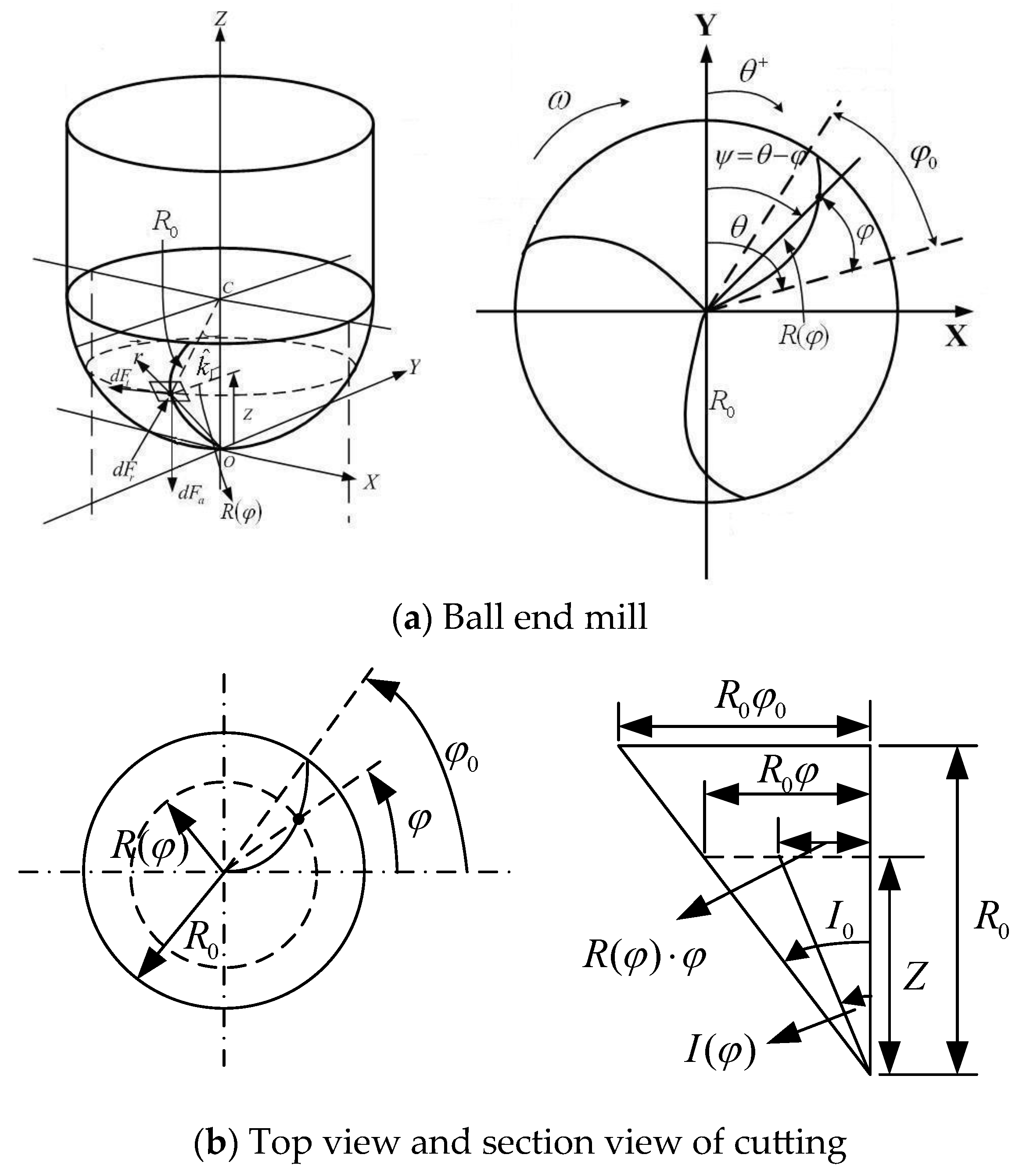
Shaiu et al. [18] presented the vibration behaviors of a rigid rotor-bearing system for ball end milling under dynamic cutting forces. This rotor system assumes the equivalent system parameters of two degrees of freedom. The gyroscopic effect had not been considered since there was no rotation of the rotor cross section. The aim of this paper is to study the vibration responses of the modeled flexible rotor-bearing system for ball end milling by using the GPEM. Figure 1 shows the ball end milling process and the corresponding model. The milling machine tool spindle is modelled as the flexible rotor-bearing system as shown in Figure 1b. In Figure 1b, the first part (I) is the spindle, the second part (II) is the spindle including the simplified tool holder, and the third part (III) is the overhang length of the tool.

3.1. Dynamic Cutting Forces

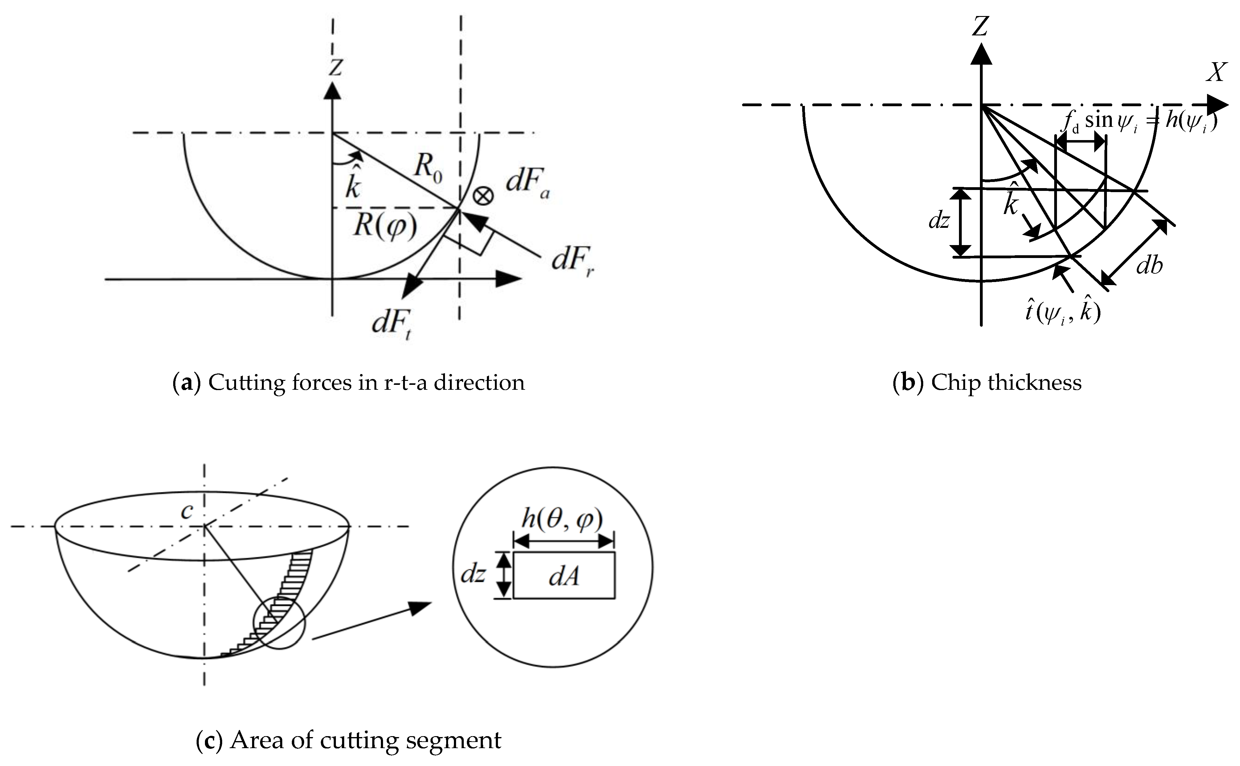
Lee and Altintas [14] introduced the linear cutting forces used in this study. The geometry of a helical ball end milling tool is given in Figure 2. Furthermore, the cutting forces, chip thickness, and area of cutting segment for ball end milling are plotted in Figure 3. d F t , d F r , and d F a are the differential dynamic cutting force components acting on the cutter along the tangential, radial, and axial directions, respectively, and are given as:
d F t = K t e   d s + K t c   t ( ψ i , k ^ )   d b d F r = K r e   d s + K r c   t ( ψ i , k ^ )   d b d F a = K a e   d s + K a c   t ( ψ i , k ^ )   d b
where K te ,   K re ,   K ae represent the edge force coefficients along the tangential, radial, and axial directions and d   s represents the differential segment length of the curved cutting edge. K tc ,   K rc ,   K ac represent the cutting force coefficients (or shear force coefficients) along the tangential, radial, and axial l directions t ^ ( ψ i , k ^ ) = h ( ψ i ) sin k ^  denotes the uncut chip thickness normal to cutting edge, in which ψ i denotes the instantaneous angular immersion in the global coordinate system, and k ^ represents the angle in a vertical plane between the z-axis and a point on the flute, h ( ψ i ) is the thickness of the instantaneous chip. d   b = d   z / sin k ^ represents the differential length of the cutting edge, in which d   z is differential axial height. The differential curve length d   s , the area of cutting segment d   A , and the angular position ψ i are derived as follows:
d s = f 1 ( φ ) R 0 d φ
d A = t ^ ( ψ i , k ^ ) d   b = h ( ψ i ) d z = h ( ψ i ) cot I 0 R 0 d φ
ψ i ( z ) = θ + ( i 1 ) 2 π N f φ = θ + ( i 1 ) 2 π N f z R 0 tan I 0
where R 0 is the ball radius of the tool, φ = z R 0 tan I 0 represents the lag angle between the tip and a point on the helical flute at height z, i is the number of flute, I 0 is the helix angle, θ is measured clockwise from + y axis, N f is total number of flutes, and z is the Z-coordinate of a point located on the cutting edge. The coefficient f 1 ( φ ) is listed in Appendix B.
If the tool position does not vary much during the short cuts [16], the chip thickness becomes:
h ( ψ i ) [ ( f d + x ( t j ) x ( t j 1 ) ] sin ψ i + [ y ( t j ) y ( t j 1 ) ] cos ψ i
where f d represents feed per tooth. x ( t j ) and y ( t j ) represent the current tool-tip deflections. x ( t j 1 ) and y ( t j 1 ) represent the tool-tip deflections at the previous time.
The radial, tangential, and axial forces are zero when the tool is not in cut. This can be modeled by multiplying the equations described as the force by a function W ( ψ i ) , which is defined when a tooth is in or out of cut. Moreover, the tooth is in cut if θ a + 2 ( n 1 ) π ψ i θ b + 2 ( n 1 ) π , where n is the number of spindle rotation, and θ a and θ b are the start and exit angles, respectively. This function is given by:
W ( ψ i ) = 1 , θ a + 2 ( n 1 ) π ψ i θ b + 2 ( n 1 ) π 0 , e l s e
Substituting Equations (4), (5) and (7) into Equation (3) yields the following equation:
d F t = [ K t e f 1 ( φ ) + K t c ( f 2 ( ψ i ) + f 3 ( ψ i ) ) ]   W ( ψ i )   R 0   d φ d F r = [ K r e f 1 ( φ ) + K r c ( f 2 ( ψ i ) + f 3 ( ψ i ) ) ]   W ( ψ i )   R 0   d φ d F a = [ K a e f 1 ( φ ) + K a c ( f 2 ( ψ i ) + f 3 ( ψ i ) ) ]   W ( ψ i )   R 0   d φ
where the coefficients f 2 ( ψ i ) and f 3 ( ψ i ) are listed in Appendix B.
Using the coordinate transformation, the differential cutting forces in Equation (9) are expressed in Cartesian coordinate as:
d F x d F y d F z = sin k ^ sin ψ i cos ψ i cos k ^ sin ψ i sin k ^ cos ψ i sin ψ i cos k ^ cos ψ i cos k ^ 0 sin k ^   d F r d F t d F a
Integrating the differential cutting forces in Equation (10), the authors [18] gave the cutting force components at the tool rotation angle θ in Cartesian coordinates and expressed in terms of the tool-tip responses as follows:
F x F y F z = i = 1 N f φ = 0 φ = φ a d F x d F y d F z = F x 1 ( θ ) F x 2 ( θ ) F y 1 ( θ ) F y 2 ( θ ) F z 1 ( θ ) F z 2 ( θ ) x ( t j ) y ( t j ) + F x 3 ( θ ) F y 3 ( θ ) F z 3 ( θ )
where φ a = a ^ R 0 tan I 0 in which a ^ represents axial depth of cut. F x i ( θ ) , F y i ( θ ) , and F z i ( θ ) , i = 1 ,   2 ,   3 are given in Appendix B.

3.2. Responses of System Using GPEM

The dynamic cutting forces expressed in Equation (10) are the external forces of the modeled flexible rotor-bearing system for ball end milling. The GPEM will be applied to solve the vibration problem of the tool-tip for ball end milling combined with the rotor-bearing system. Applying the transformation relation in Equation (1), the tool-tip deflections x ( t j ) and y ( t j ) can be transformed into the generalized coordinates a n ( t ) and b m ( t ) shown below:
x ( t j ) = u ( l l , t ) = n = 1 N p a n ( t ) ( l l ) n 1 y ( t j ) = v ( l l , t ) = m = 1 N p b m ( t ) ( l l ) m 1
Substitute Equation (12) into Equation (10) to yield the force terms of ball end mill in generalized coordinates.
F x F y F z = F x 1 ( θ ) F x 2 ( θ ) F y 1 ( θ ) F y 2 ( θ ) F z 1 ( θ ) F z 2 ( θ ) n = 1 N p a n ( t ) m = 1 N p b m ( t ) + F x 3 ( θ ) F y 3 ( θ ) F z 3 ( θ )
Applying the principle of virtual work to the generalized coordinate system and neglecting the z-direction force F z , the external forces F x and F y in Equation (13) can be rewritten as the right side of Equation (2) with generalized coordinates. Therefore, Equation (2) can be modified into the following equation for the whole tool spindle system.
M 0 0 M a ¨ b ¨ + Ω 0 G G 0 a ˙ b ˙ + C xx C xy C yx C yy a ˙ b ˙ + K s + K xx K xy K yx K s + K yy a b = F x 1 ( θ )   Φ F x 2 ( θ )   Φ F y 1 ( θ )   Φ F y 2 ( θ )   Φ a b + F x 3 ( θ )   d F y 3 ( θ )   d
where Φ = 1 0 1 1 . 1 N p 2 1 N p 1 1 1 1 2 . 1 N p 1 1 N p . . . . . 1 N p 2 1 N p 1 . 1 2 N p 4 1 2 N p 3 1 N p 1 1 N p . 1 2 N p 3 1 2 N p 2 and d =   1 0 1 1 1 N p 2 1 N p 1 T .
It should be noted that the first part of the milling force, on the right side of Equation (14), can be combined with the stiffness matrix to change the system parameters of the rotor-bearing system. The cutting forces, which depend, in part, on the tool-tip response, are combined with the rotor system to complicate the problem, and the calculated response becomes more accurate. Expressing Equation (14) into the state space form as X ˙ k = [ A ] X k + B , with X k = a ˙ b ˙ a b T at time t k , the matrix [ A ] and the vector B are derived as:
[ A ] = M 0 0 0 0 M 0 0 0 0 I 0 0 0 0 I 1 C xx C xy Ω G K s K xx + F x 1   Φ K xy + F x 2   Φ C yx + Ω G C yy K yx + F y 1   Φ K s K yy + F y 2   Φ I 0 0 0 0 I 0 0 B = M 0 0 0 0 M 0 0 0 0 I 0 0 0 0 I 1 F x 3   d F y 3   d 0 0
The X k at time t k can be solved by using the numerical method. The displacement of tool-tip in the x direction and the y direction can be determined as a 1 ( t ) + a 2 ( t ) + + a N P ( t ) and b 1 ( t ) + b 2 ( t ) + + b N P ( t ) , respectively. Furthermore, the natural frequency can also be determined by solving the eigenvalue problem of Equation (14).

3.3. Numerical Results and Discussion

The vibration responses of the tool-tip for ball end milling are solved numerically using the GPEM for the flexible rotor-bearing system in this study. The used cutting conditions and the cutting parameters are given in Table 1 [14,18]. The cutting force coefficients K ac ,   K tc ,   K rc are given in Appendix C. Table 2 gives the configuration data for the rotor-bearing system modeled in Figure 1b. E and ρ represent the shaft elastic modulus and density, respectively. d O and d I represent the shaft outer and inner diameters, respectively.
The authors in [18] proposed the approximated critical speeds of the spindle N c r (rpm) as:
N c r = f n 2 π ( m k N f ) × 60 ,     m k = 1 ,   2 ,   3 ,  
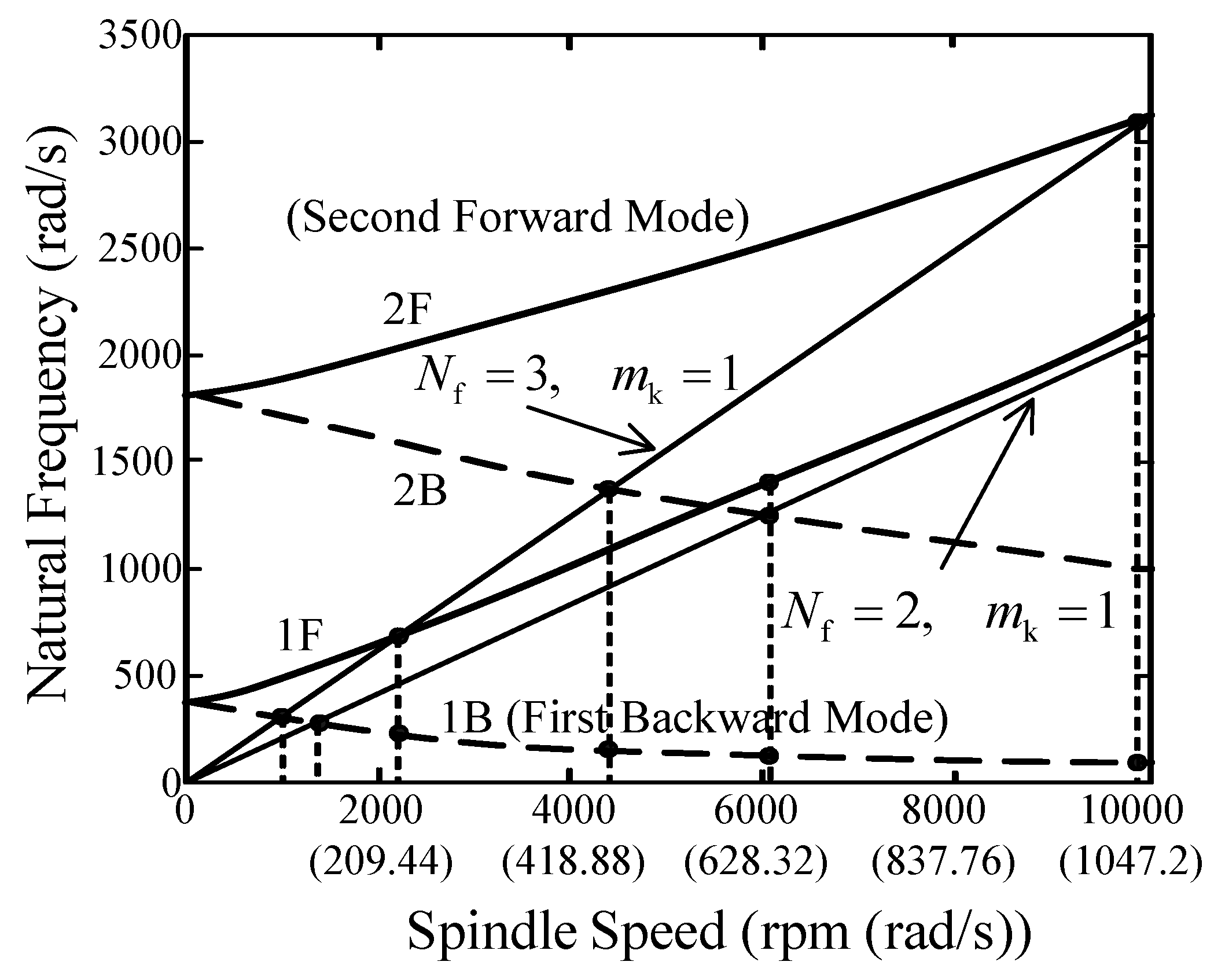
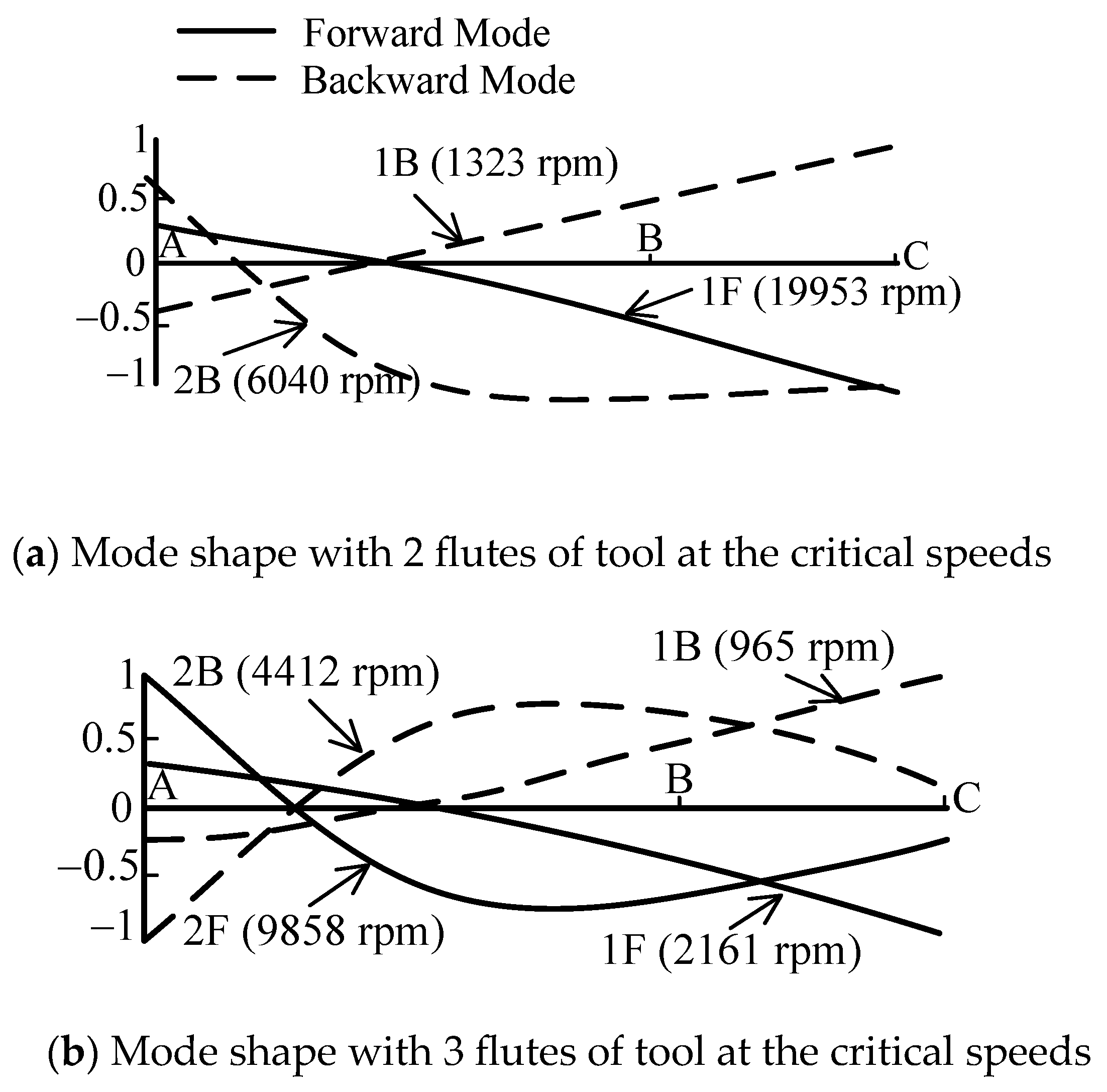
where f n (rad/s) represents the natural frequency of the tool-tip, N f represents the flute number, and m k represents the vibration cycle number of the tool from one flute to another during cutting. Different combinations of m k and N f lead to different excitation lines in the whirl map of the flexible rotor-bearing system, which will give different relationships between natural frequency and critical speed. Figure 4 is the whirl map which shows that the forward and backward modes are excited in the flexible rotor system under spindle speeds. The natural frequencies of forward mode increase as spindle speeds increase, but those of backward mode decrease as spindle speeds increase. The parameters N f and m k determine the excitation line in the whirl map. In this study, m k = 1 , and two cases including N f = 2, 3, are used. Thus, the two whirl ratios are 1/2 and 1/3. The excitation line may intersect the natural mode curves at some corresponding spindle speeds, called the critical speeds. The natural frequencies and critical speeds of various modes can be expressed in Table 3 to show that the critical speeds of forward mode are higher than those of backward mode. Their associated mode shapes of forward and backward modes at critical speeds, with 2 and 3 flutes of the tool, are expressed in Figure 5. It is shown that the eigenvector magnitude for the mode 1 is the largest at tool-tip C, but those for the mode 2 is relatively small. In addition, when the spindle rotates at a higher critical speed, the frequency difference between the forward mode and backward mode becomes larger. This phenomenon is mainly due to the gyroscopic effect of the flexible rotor. Therefore, some lower natural modes will be significantly excited to become the main components of the tool-tip response. This will be verified in this section.
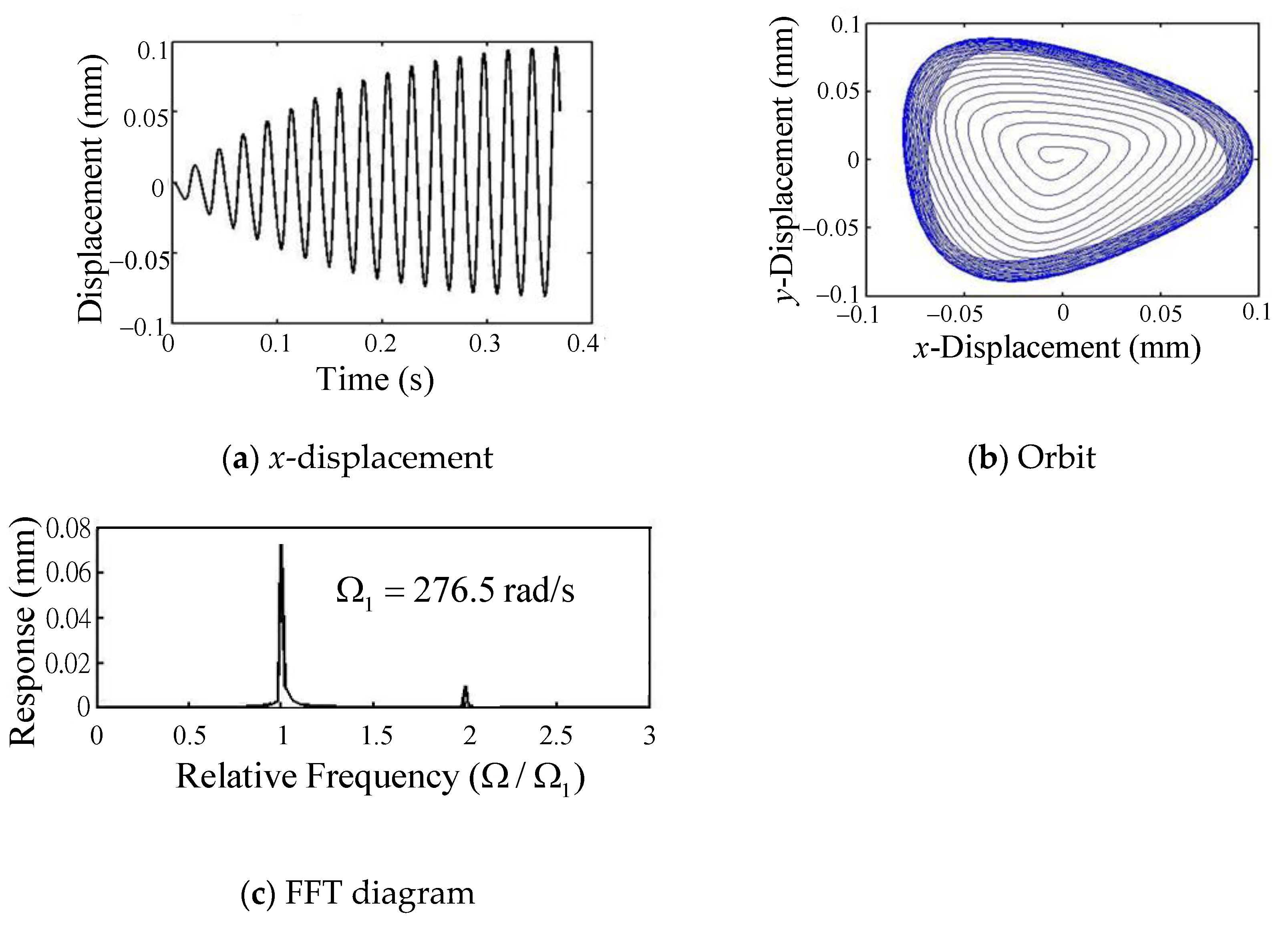
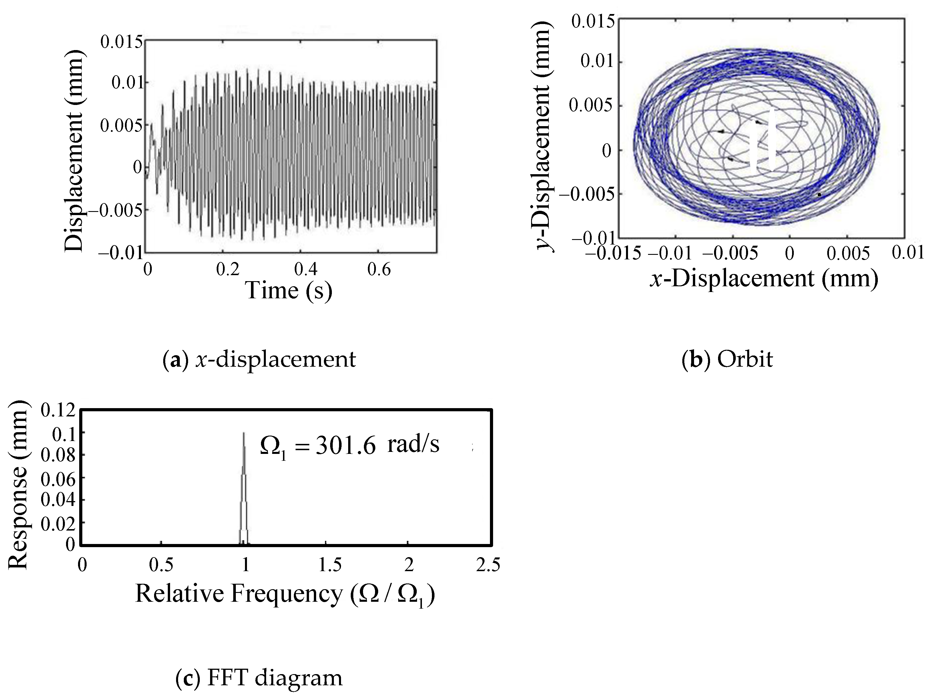
N f = 2 : The numerical studies for N f = 2 at different spindle speed are shown in Figure 6, Figure 7 and Figure 8. Figure 6a shows the displacement of the tool-tip with two flutes in the x direction, at the spindle speed of 1320 rpm, which is close to the critical speed of the first backward mode. Figure 6b also shows the x-y plane orbit of the tool-tip. The orbit is an encircled trajectory which expands clockwise around the origin in a stable loop. This mode is verified to be a backward mode. The fast Fourier transformation diagram (FFT diagram) for the tool-tip response in the x direction, at the spindle speed of 1320 rpm, is shown in Figure 6c. The tool is with two flutes. It is found that only one major peak, with the frequency of 276.5 rad/s, dominates the response of the rotor system.
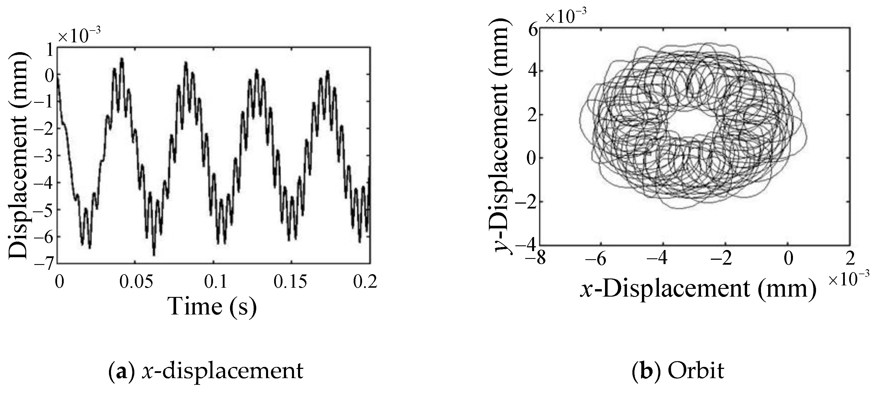
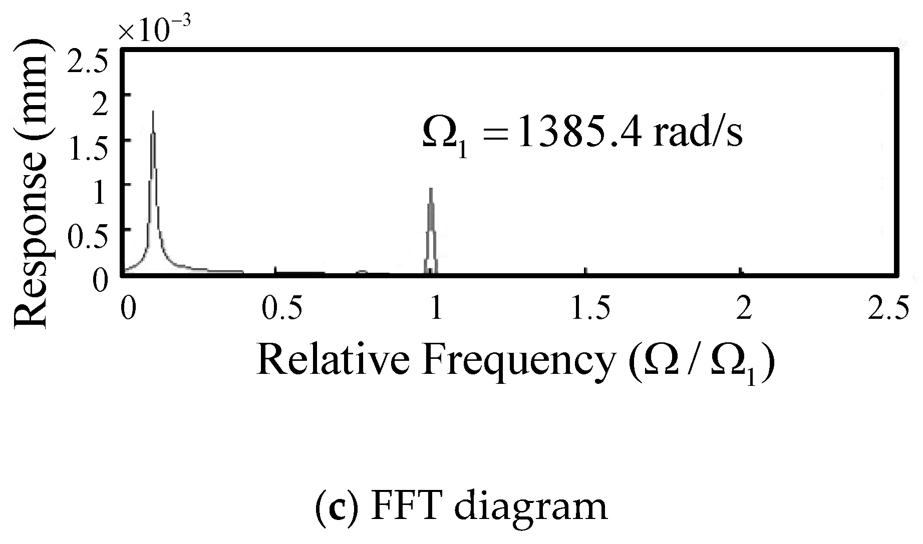
Figure 7a shows the displacement in the x direction of the tool-tip with two flutes, at the spindle speed of 6040 rpm, which is close to the critical speed of the second backward mode. It is found that the tool oscillates with the cutting-force frequency combined with a longer cycle vibration. The period of the long cycle is about 0.056 s, which explains how the workpiece surface is often found to have a lot of small waves inside the long cycle wave in the practical milling. From Figure 4, it can be seen that the lower first backward mode with the natural frequency of 112.1 rad/s is excited at the spindle speed of 6040 rpm. Figure 7b plots the tool-tip orbit. It can be seen from the figure that the track of the tip of the tool circles around, and there are many small rings inside. The large ring is excited by the second backward mode, and the small ring corresponds to the first backward mode. This phenomenon can be more clearly observed from the FFT plot shown in Figure 7c. At the spindle speed of 6040 rpm with two flutes, there are two main peaks in the x-response of the tool-tip. The two frequencies governing the behaviors of tool-tip correspond to the first and second backward modes, respectively. The obvious low frequency peak verifies the long cycle wave phenomenon. A very small peak near the right hand of cutting-force frequency is also found. It can be seen, from Figure 4, to coincide with the first forward mode at the spindle speed of 6040 rpm.
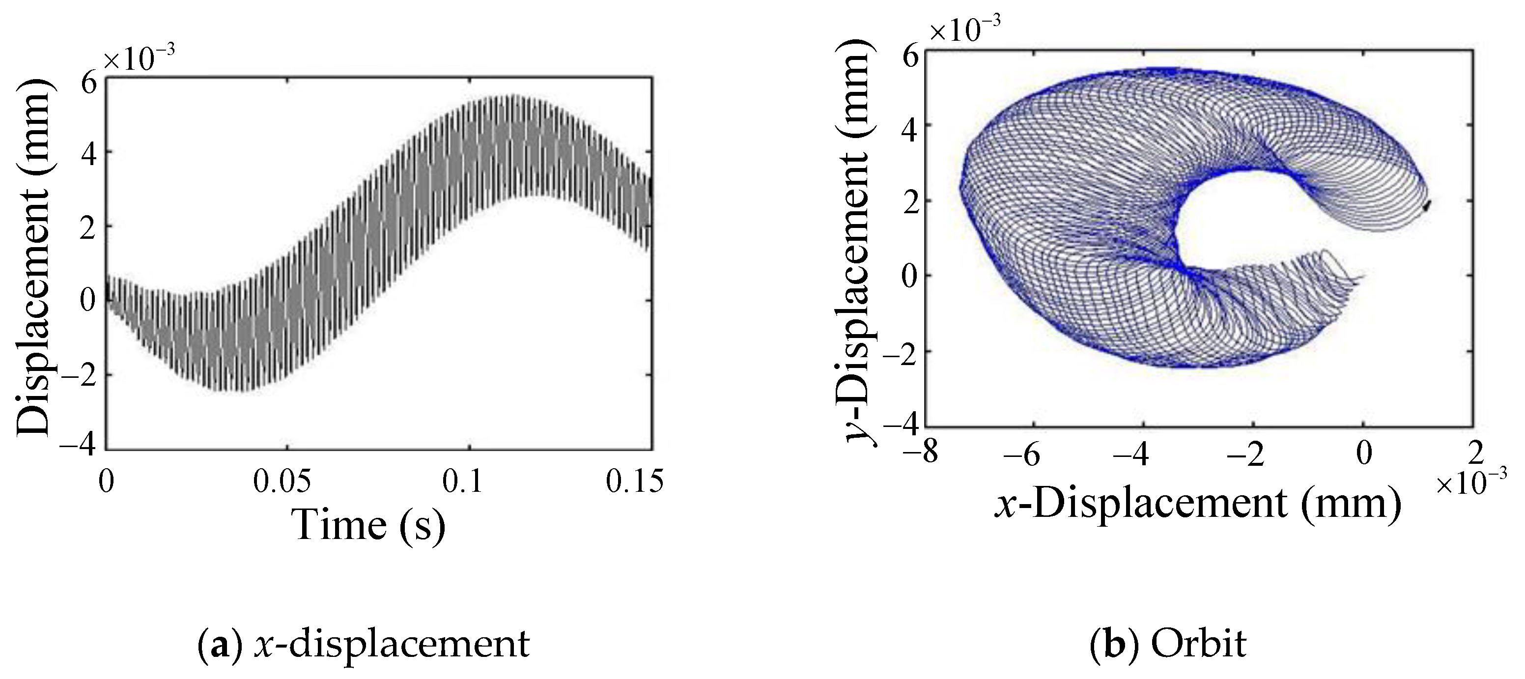
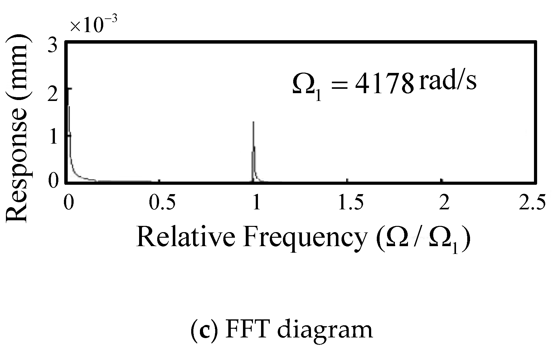
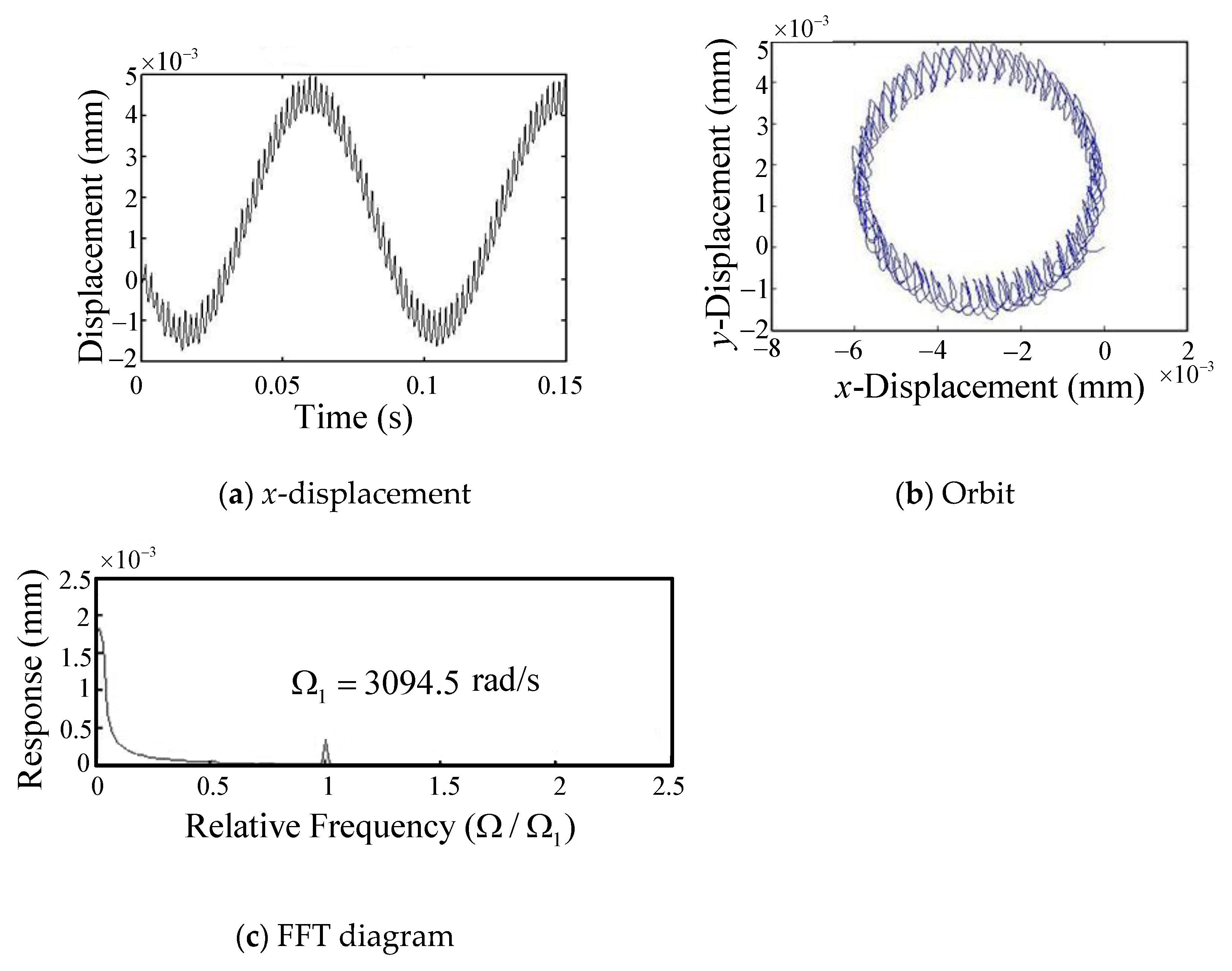
Figure 8a shows the displacement of the tool-tip with two flutes in the x direction, at the spindle speed of 19,950 rpm, which is close to the critical speed of the first forward mode. It is found that the tool oscillates with the cutting-force frequency combined with a longer cycle vibration. The period of the long cycle is 0.173 s because the first backward mode is excited and the associated natural frequency is 36.31 rad/s. The period of long cycle at spindle speed 19,950 rpm is larger than that at spindle speed 6040 rpm. Figure 8b plots the orbit of the tool-tip. It shows the orbital trajectory of the tool-tip around a large circle, with many smaller inner circles. The encircled directions of small inner loops are anticlockwise, so this mode is dominated by the forward mode (second forward mode), and the encircled direction of large circle is clockwise, so this mode is dominated by the backward mode (first backward mode). Figure 8c shows the FFT plot of the x-response of the tool-tip with two flutes at the spindle speed of 19,950 rpm. Two frequencies govern the behaviors of the tool-tip vibration. An obvious low-frequency peak is found to verify that the first backward mode is excited. This is the long cycle wave phenomena.
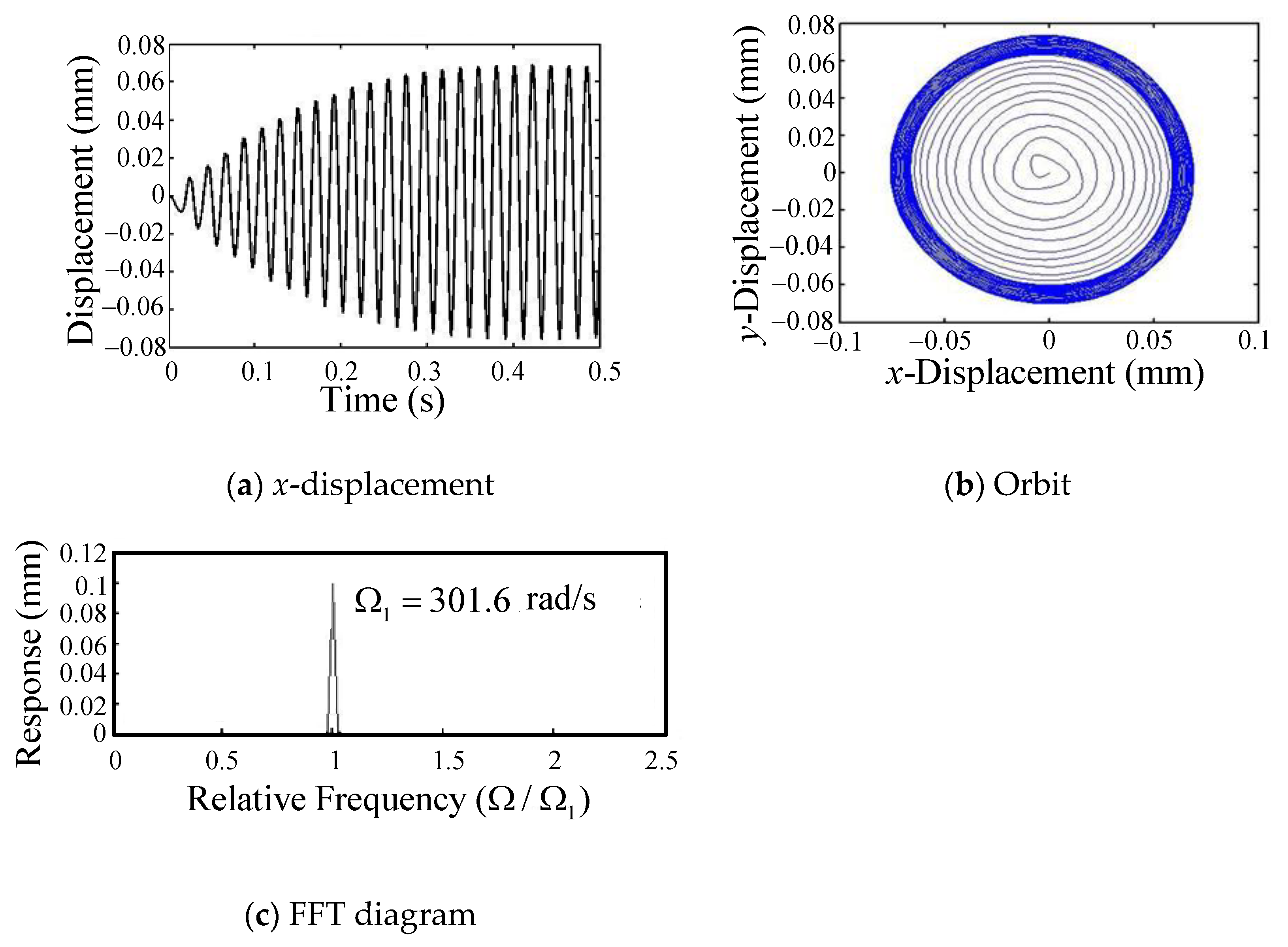
N f = 3 : Figure 9, Figure 10, Figure 11 and Figure 12 show the numerical studies for N f = 3 at different spindle speed. The tool-tip displacement in x direction with three flutes is shown in Figure 9a. The spindle speed is 960 rpm, close to the critical speed of the first backward mode. Figure 9b shows the orbit of the tool-tip. It shows that an encircled trajectory of the tool-tip expands clockwise around the origin in a stable loop. This phenomenon is the same as in Figure 6b, because only the first backward mode of the rotor-bearing system is excited. Figure 9c shows the FFT plot of the x-response of the tool-tip with three flutes at the spindle speed of 960 rpm. Only one dominant frequency is found to dominate the response of the tool-tip.
Figure 10a shows the displacement in the x direction of the tool-tip with three flutes, at the spindle speed of 2160 rpm, which is close to the critical speed of the first forward mode. The orbit of tool-tip is plotted in Figure 10b. The result shows an encircled trajectory of the tool-tip expands anticlockwise around the origin in a stable loop, so this mode is dominated by a forward mode. Figure 10c shows the FFT plot of the x-response of the tool-tip with three flutes at the spindle speed of 2160 rpm. A distinct peak with a frequency of 678.6 rad/s, and a far smaller peak with a frequency of 237.7 rad/s, are found.
Figure 11a shows the displacement of the tool-tip with three flutes in the x direction, at the spindle speed of 4410 rpm, which is close to the critical speed of the second backward mode. The tool oscillates with the cutting-force frequency combined with a longer cycle vibration which is the first backward mode with a natural frequency of 138.54 rad/s. The period of the long cycle is 0.045 s. Figure 11b plots the orbit of the tool-tip. It shows that the trajectory of the tool-tip goes around a large circle with many smaller inner loops. The FFT plot for the x-response of the tool-tip with three flutes at the spindle speed of 4410 rpm is shown in Figure 11c. There are two major peaks that govern the vibration of the tool-tip. The obvious low frequency peak, dominated by the first backward mode, corresponds to the long cycle wave phenomena.
Figure 12a shows the displacement of the tool-tip with three flutes in the x direction, at the spindle speed of 9850 rpm, which is close to the critical speed of the second forward mode. The tool oscillates with the cutting-force frequency combined with a longer cycle vibration. The long cycle vibration corresponds to the first backward mode with a natural frequency of 71.17 rad/s. The period of the long cycle is 0.088 s. Figure 12b shows the orbit of the tool-tip, which wraps around a large circle with many small inner rings. Figure 12c shows the FFT plot of the x-response of the tool-tip with three flutes at the spindle speed of 9850 rpm. It is found that there are two frequencies governing the behaviors of the tool-tip. An obvious low-frequency peak is found. It corresponds to the long cycle wave phenomena, and verifies that the first backward mode is excited.
From a comparison of Figure 6, Figure 7 and Figure 8 and comparison of Figure 9, Figure 10, Figure 11 and Figure 12, it can be seen that the period of the long cycle vibration enlarges as the spindle speed increases. To gain an insight into the phenomenon, it can be seen from Figure 4 that, with the increase in the spindle speed, the natural frequency of the first backward mode decays. Additionally, in the numerical study, it is found that the long cycle vibration is majorly dominated by the first backward mode, thus, the period of the long cycle vibration enlarges as the spindle speed increases. In addition, it can also be seen from the FFT diagram that the peak at the first backward mode (the long-period vibration) becomes larger compared with the peak at the cutting force frequency as the spindle speed becomes larger. The tool-tip response including the forward mode and backward mode is mainly dependent on the spindle speed. The forward and backward modes that vary with the spindle speed are mainly caused by the gyroscopic effect of the flexible rotor. The vibration analysis of a ball end mill is more accurate if the spindle is modelled as a flexible rotor, taking into account the gyroscopic effects caused by the rotation of the rotor section. The cutting forces, which depend, in part, on the tool-tip response, combine with the stiffness matrix of the rotor system to complicate the issue. Therefore, in order to obtain a more accurate vibration analysis for ball end milling, the flexible rotor-bearing system cannot be omitted.

4. Conclusions

The dynamic behaviors of the flexible rotor-bearing system for ball end milling were first numerically investigated by using the GPEM. The tool-tip responses have been made more realistic due to consideration of the coupling effect of the flexible rotor-bearing system. Thanks to the gyroscopic effect of the flexible rotor, the important whirl map can be drawn. Then, it can be observed from the whirl map that, the critical speeds, which are directly proportional to the natural frequency and inversely proportional to the number of flutes, due to some natural modes, can be excited to significantly affect the tool responses. The flexible isotropic rotor-bearing system with rotating speed can excite the forward and backward modes along the excitation line in the whirl map to form two different critical speeds. In addition, the cutting forces, which depend, in part, on the tool-tip response, combine with the stiffness matrix of the rotor system to complicate the issue. To the best of the authors’ knowledge, most previous studies on ball end milling always ignore the rotor system or assume that the rotor is rigid or discretized to a few degrees of freedom, thereby ignoring the gyroscopic effect of the flexible rotor. Unlike the previous literature, the natural frequency in this study varies with the spindle speed. Thanks to the gyroscopic effect of the flexible rotor, which of the different modes are included in the tool-tip response depend mainly on the spindle speed. The model established by considering the coupling effect of the flexible rotor and using GPEM can be more efficient and realistic in analyzing the dynamic behavior of the tool-tip. The important new findings of the present study, by using numerical analysis, are obtained as follows:
  • In milling at a higher spindle speed (2160–19,950 rpm), the tool-tip oscillates with the cutting-force frequency combined with a longer cycle vibration of the first backward mode due to the coupling effects of the flexible rotor-bearing system, and the period of the long cycle vibration enlarges as the spindle speed increases. From the FFT plot, it can be seen that as the spindle speed becomes larger, the peak amplitude at the first backward mode (long-period vibration) becomes larger compared to the peak at the cutting force frequency.
  • Under lower spindle speed milling (960, 1320 rpm), the vibration trajectory of the tool-tip in the co-plane expands clockwise gradually around the origin until arriving at a stable loop. This is because only the first backward mode of the rotor-bearing system is excited.
The authors of [18] calculated the critical speeds of the rotor-bearing system for ball end milling and verified the numerical results with the experimental data. However, the rotor was assumed to be rigid and the lateral rotation was neglected, so the gyroscopic effects of the system could not be included. Therefore, the critical speed was independent of the spindle speed and only one mode was calculated. In this study, the critical speeds of the flexible rotor-bearing system vary with the spindle speed due to the gyroscopic effect. The vibration responses of the tool-tip, including forward and backward modes, are numerically calculated. However, it is also recommended that future work is required to add a comparison by setting up an experiment to validate the presented results.

Author Contributions

Conceptualization, C.-J.H., J.-R.C., T.-N.S. and K.-H.C.; formal analysis, C.-J.H. and J.-R.C.; investigation, K.-H.C.; methodology, C.-J.H., T.-N.S. and K.-H.C.; software, K.-H.C.; supervision, T.-N.S.; validation, C.-J.H. and J.-R.C.; writing—original draft, J.-R.C. and K.-H.C.; writing—review and editing, C.-J.H., J.-R.C. and T.-N.S. All authors have read and agreed to the published version of the manuscript.

Funding

This research received no external funding.

Institutional Review Board Statement

Not applicable.

Informed Consent Statement

Not applicable.

Data Availability Statement

Not applicable.

Conflicts of Interest

The authors declare no conflict of interest.

Nomenclature

a ,   b ,   c section length of tool spindle
a ^ axial depth of cut
a n ( t ) ,   b m ( t ) generalized coordinates
A ( z ) cross-sectional area of the shaft
c tool length
C x x ,   C x y ,   C y x ,   C y y damping matrix of the bearing using GPEM
C xxj b ,   C xyj b , C yxj b ,   C yyj b damping coefficients of the j-th bearing
d O ,   d I outer and inner diameter of the shaft and tool
d A area of cutting segment
d b differential cutting edge length
d F t , d F r , d F a differential cutting forces in tangential, radial, and axial direction
d F x , d F y , d F z differential milling force in Cartesian coordinate
d s differential length of the curved cutting edge segment
d z differential height in axial direction
E ( z ) elastic modulus of the shaft and tool
f d feed per tooth ( mm )
f n natural frequency ( rad / s )
f 1 ( φ ) ,   f 2 ( ψ i ) ,   f 3 ( ψ i ) coefficients of cutting force
G gyroscopic matrix of the rotor using GPEM
h chip thickness
I 0 helix angle at meeting boundary between the ball and shank
I D ,   I P diametral and polar mass moment of inertia of the shaft
I Di d ,   I Pi d diametral and polar mass moment of inertia of the i-th disk
K s stiffness matrix of the shaft using GPEM
K tc , K rc , K ac tangential, radial, and axial cutting force coefficients
K te , K re , K ae tangential, radial, and axial edge force coefficients
K x x ,   K x y ,   K y x ,   K y y stiffness matrix of the bearing using GPEM
K xxj b ,   K xyj b , K yxj b ,   K yyj b elastic constant of the j-th bearing
k ^ angle in a vertical plane between a point on the flute and the z-axis
l total length of the tool spindle
M mass matrix of the rotor using GPEM
m i d mass of the i-th disk
m k vibration cycle number of tool during the cutting time from one flute to another
N d total number of the disk
N f total number of the flutes
N b total number of the bearing
N p total number of polynomial
N f number of flute
N c r critical speed in rpm
R 0 ball radius of tool
R ( φ ) tool radius in x-y plane at a point defined by φ
t ^ ( ψ i , k ^ ) uncut chip thickness normal to cutting edge in milling
x ( t j ) , y ( t j ) deflections of tool-tip at the present time
α rake angle of cutting parameter
β friction angle of cutting parameter
γ chip compression ratio of cutting parameter
ρ ( z ) density of the shaft and tool
θ tool rotation angle, measured from y-axis (CW)
θ a , θ b the start and exit angles in the milling process
φ lag angle between the tip (z = 0) and a point on the helical flute at height z
ψ i instantaneous angular immersion in the global coordinate system
τ shear stress of cutting parameter
Ω spindle speed

Appendix A

After defining z ^ = z l , the components of the N p × N p matrices in Equation (2) are as follows:
M ( m , n ) = 0 1   ρ ( z ^ ) A ( z ^ )   z ^ n + m 2 d z + 0 1   ( n 1 ) ( m 1 ) I D   z ^ n + m 4 d z ^ + i = 1 N d [ m i d ( z ^ i d ) n + m 2 + ( n 1 ) ( m 1 )   I Di d ( z ^ i d ) n + m 4 ] ,
G ( m , n ) = 0 1   ( n 1 ) ( m 1 ) I P   z ^ n + m 4 d z + i = 1 N d [ ( n 1 ) ( m 1 )   I Pi d ( z ^ i d ) n + m 4 ] ,
C xx ( m , n ) = i = 1 N b [ C xxi b ( z ^ i d ) n + m 2 ] ,
C xy ( m , n ) = i = 1 N b [ C xyi b ( z ^ i d ) n + m 2 ] ,
C yy ( m , n ) = i = 1 N b [ C yyi b ( z ^ i d ) n + m 2 ] ,
K s ( m , n ) = 0 1   ( n 1 ) ( n 2 ) ( m 1 ) ( m 2 )   E ( z ^ ) I ( z ^ )   z ^ n + m 6 d z ^ ,
K xx ( m , n ) = i = 1 N b [ K xxi b ( z ^ i d ) n + m 2 ] ,
K xy ( m , n ) = i = 1 N b [ K xyi b ( z ^ i d ) n + m 2 ] ,
K yy ( m , n ) = i = 1 N b [ K yyi b ( z ^ i d ) n + m 2 ]
where l and z represent the shaft length and axial coordinate, respectively. N p , N d , and N b denote the total number of polynomial, disk, and bearing, respectively. ρ ( z ^ ) and A ( z ^ ) represent the shaft density and cross-sectional area, respectively. I D and I P represent the shaft diametral and polar mass moment of inertia, respectively. m i d represents the i-th disk mass. I Di d and I Pi d represent the i-th disk diametral and polar mass moment of inertia, respectively. C xxj b , C xyj b , and C yyj b represent the j-th bearing damping coefficients. E ( z ^ ) and I ( z ^ ) represent the shaft elastic modulus and cross-sectional moment of inertia, respectively. K xxj b , K xyj b   , and K yyj b represent the j-th bearing elastic constant.

Appendix B

f 1 φ = cot I 0 1 φ cot I 0 2 φ 2 φ cot I 0 + 2 φ cot I 0 + 1 φ 2 cot 2 I 0 1 / 2 ,
f 2 ( ψ i ) = [ ( f d x ( t j 1 ) ) sin ψ i y ( t j 1 ) cos ψ i ] cot I 0
f 3 ( ψ i ) = [ x ( t j ) sin ψ i + y ( t j ) cos ψ i ] cot I 0
F x 1 ( θ ) = i = 1 N f ϕ = 0 ϕ a 0 F 2 x 0 F 4 x 0 F 6 x   K ^   W ( ψ i )   R 0   d ϕ
F x 2 ( θ ) = i = 1 N f φ = 0 φ a 0 F 2 y 0 F 4 y 0 F 6 y   K ^   W ( ψ i )   R 0   d φ
F x 3 ( θ ) = i = 1 N f φ = 0 φ a F 1 F 2 F 3 F 4 F 5 F 6   K ^   W ( ψ i )   R 0   d φ
F y 1 ( θ ) = i = 1 N f φ = 0 φ a 0 G 2 x 0 G 4 x 0 G 6 x   K ^   W ( ψ i )   R 0   d φ
F y 2 ( θ ) = i = 1 N f φ = 0 φ a 0 G 2 y 0 G 4 y 0 G 6 y   K ^   W ( ψ i )   R 0   d φ
F y 3 ( θ ) = i = 1 N f φ = 0 φ a G 1 G 2 G 3 G 4 G 5 G 6   K ^   W ( ψ i )   R 0   d φ
where K ^ = K r e K r c K t e K t c K a e K a c T and φ a = a ^ R 0 tan I 0 . The parameters F k , G k ( k = 1 ,   2 ,   6 ), F k x , F k y , G k x , and G k y ( k = 2 ,   4 ,   6 ) are given in Table A1.
Table A1. The parameters in Equations (A13)–(A18).
F 2 x = sin k ^ sin 2 ψ i cot I 0 F 4 x = cos ψ i sin ψ i cot I 0 F 6 x = cos k ^ sin 2 ψ i cot I 0
F 2 y = sin k ^ sin ψ i cos ψ i cot I 0 F 4 y = cos 2 ψ i cot I 0 F 6 x = cos k ^ sin ψ i cos ψ i cot I 0
F 1 = sin k ^ sin ψ i f 1 ( φ ) F 2 = sin k ^ sin ψ i f 3 ( ψ i ) F 3 = cos ψ i f 1 ( φ )
F 4 = cos ψ i f 3 ( ψ i ) F 5 = cos k ^ sin ψ i f 1 ( φ ) F 6 = cos k ^ sin ψ i f 3 ( ψ i )
G 2 x = sin k ^ cos ψ i sin ψ i cot I 0 G 4 x = sin 2 ψ i cot I 0 G 6 x = cos k ^ cos ψ i sin ψ i cot I 0
G 2 y = sin k ^ cos 2 ψ i cot I 0 G 4 y = sin ψ i cos ψ i cot I 0 G 6 y = cos k ^ cos 2 ψ i cot I 0
G 1 = sin k ^ cos ψ i f 1 ( φ ) G 2 = sin k ^ cos ψ i f 3 ( ψ i ) G 3 = sin ψ i f 1 ( φ )
G 4 = sin ψ i f 3 ( ψ i ) G 5 = cos k ^ cos ψ i f 1 ( φ ) G 6 = cos k ^ cos ψ i f 3 ( ψ i )

Appendix C

The cutting force coefficients K tc ,   K rc ,   K ac can be expressed in terms of the modified mechanics of cutting analysis variables as follows [14]:
K t c = τ [ cos ( β n α n ) + tan η c sin β n tan I ( φ ) ] c sin ϕ n ,
K r c = τ sin ( β n α n ) c sin ϕ n cos I ( φ ) ,
K a c = τ [ cos ( β n α n ) tan I ( φ ) tan η c sin β n ] c sin ϕ n
where c = cos 2 ( ϕ n + β n α n ) + tan 2 η c sin 2 β n , τ is the shear stress, β is the friction angle, and γ is the chip ratio. Assume that the chip flow angle η c is equal to the helix angle I at the analyzed edge segment and that the normal rake angle α n is equal to the local rake angle α . The normal shear angle ϕ n can be given as:
tan ϕ n = γ cos α n 1 γ sin α n ,
The normal friction angle β n is given as:
tan β n = tan β cos η c ,
and the relation of the normal shear angle ϕ n and the normal friction angle can be shown as:
tan ( ϕ n + β n ) = cos α n tan I tan η c sin α n tan I .

References

  1. Lund, J.W.; Orcutt, F.K. Calculations and experiments on the unbalance response of a flexible rotor. J. Eng. Ind. 1967, 89, 785–796. [Google Scholar] [CrossRef]
  2. Lund, J.W. Stability and damped critical speeds of a flexible rotor in fluid-film bearings. J. Eng. Ind. 1974, 96, 509–517. [Google Scholar] [CrossRef]
  3. Chu, F.H.; Pilkey, W.D. A direct integration technique for the transient analysis of rotating shafts. J. Mech. Des. 1982, 104, 384–388. [Google Scholar] [CrossRef]
  4. Gu, J. An Improved Transfer matrix-direct integration method for rotor dynamics. J. Vib. Acoust. 1986, 108, 182–188. [Google Scholar] [CrossRef]
  5. Nelson, H.D. A finite rotating shaft element using Timoshenko beam theory. J. Mech. Des. 1980, 102, 793–803. [Google Scholar] [CrossRef]
  6. Ruhl, R.L.; Booker, J.F. A finite element model for distributed parameter turborotor systems. J. Eng. Ind. 1972, 94, 126–132. [Google Scholar] [CrossRef]
  7. Nelson, H.D.; McVaugh, J.M. The dynamics of rotor-bearing systems using finite elements. J. Eng. Ind. 1976, 98, 593–600. [Google Scholar] [CrossRef]
  8. Subbiah, R.; Kumar, A.S.; Sankar, T.S. Transient dynamic analysis of rotors using the combined methodologies of finite elements and transfer matrix. J. Appl. Mech. 1988, 55, 448–452. [Google Scholar] [CrossRef]
  9. Shiau, T.N.; Hwang, J.L. A new approach to the dynamic characteristic of undamped rotor-bearing systems. J. Vib. Acoust. 1989, 111, 379–385. [Google Scholar] [CrossRef]
  10. Shiau, T.N.; Hwang, J.L. Generalized polynomial expansion method for the dynamic analysis of rotor-bearing systems. J. Eng. Gas Turbines Power 1993, 115, 209–217. [Google Scholar] [CrossRef]
  11. Shiau, T.N.; Hwang, J.L.; Chang, Y.B. A study on stability and response analysis of a nonlinear rotor system with mass unbalance and side load. J. Eng. Gas Turbines Power 1993, 115, 218–226. [Google Scholar] [CrossRef]
  12. Shiau, T.N.; Chen, E.C.; Huang, K.H.; Hsu, W.C. Dynamic response of a spinning Timoshenko beam with general boundary conditions under a moving skew force using global assumed mode method. JSME Int. J. Ser. C 2006, 49, 401–410. [Google Scholar] [CrossRef] [Green Version]
  13. Shiau, T.N.; Huang, K.H.; Hsu, W.C. Dynamic response and stability of a rotating ball screw under a moving skew load. J. CSME 2006, 27, 297–305. [Google Scholar]
  14. Lee, P.; Altintas, Y. Prediction of ball-end milling forces from orthogonal cutting data. Int. J. Mach. Tools Manuf. 1996, 36, 1059–1072. [Google Scholar] [CrossRef]
  15. Altintas, Y.; Lee, P. Mechanics and dynamics of ball end milling. J. Manuf. Sci. Eng. Trans. 1998, 120, 684–692. [Google Scholar] [CrossRef] [Green Version]
  16. Stepan, G.; Szalai, R.; Mann, B.P.; Bayly, P.V.; Insperger, T.; Gradisek, J.; Govekar, E. Nonlinear dynamics of high-speed milling—Analyses, Numerics, and Experiments. J. Vib. Acoust. 2005, 127, 197–203. [Google Scholar] [CrossRef]
  17. Shiau, T.N.; Chen, K.H.; Chang, J.R.; Huang, M.H. Identification of system parameters for ball end milling. J. CSME 2009, 30, 95–105. [Google Scholar]
  18. Shiau, T.N.; Chen, K.H.; Chang, J.R. Critical speed analysis for nonlinear effects of rotor system and ball end milling. Int. J. Adv. Manuf. Technol. 2009, 44, 463–475. [Google Scholar] [CrossRef]
  19. Cao, H.; Li, B.; He, Z. Chatter stability of milling with speed-varying dynamics of spindles. Int. J. Mach. Tools Manuf. 2012, 52, 50–58. [Google Scholar] [CrossRef]
  20. Kalinski, K.J.; Galewski, M.A. Optimal spindle speed determination for vibration reduction during ball-end milling of flexible details. Int. J. Mach. Tools Manuf. 2015, 92, 19–30. [Google Scholar] [CrossRef]
  21. Yao, Q.; Wu, B.; Luo, M.; Zhang, D. On-line cutting force coefficients identification for bull-end milling process with vibration. Measurement 2018, 125, 243–253. [Google Scholar] [CrossRef]
  22. Zhan, D.; Jiang, S.; Niu, J.; Sun, Y. Dynamics modeling and stability analysis of five-axis ball-end milling system with variable pitch tools. Int. J. Mech. Sci. 2020, 182, 105774. [Google Scholar] [CrossRef]
  23. Cai, S.; Cai, Z.; Yao, B.; Shen, Z.; Ma, X. Identifying the transient milling force coefficient of a slender end-milling cutter with vibrations. J. Manuf. Process. 2021, 67, 262–274. [Google Scholar] [CrossRef]
  24. Miao, H.; Li, C.; Wang, C.; Xu, M.; Zhang, Y. The vibration analysis of the CNC vertical milling machine spindle system considering nonlinear and nonsmooth bearing restoring force. Mech. Syst. Signal Process. 2021, 161, 107970. [Google Scholar] [CrossRef]
  25. Li, B.; Liu, T.; Liao, J.; Feng, C.; Yao, L.; Zhang, J. Non-invasive milling force monitoring through spindle vibration with LSTM and DNN in CNC machine tools. Measurement 2023, 210, 112554. [Google Scholar] [CrossRef]
  26. Dai, Y.; Li, H.; Liu, H.; Yong, J.; Yang, C.; Wang, C.; Liu, S. Dynamics and stability analysis of five-axis ball end milling with low radial immersion considering cutter runout. J. Manuf. Process. 2023, 92, 479–499. [Google Scholar] [CrossRef]
  27. Qin, S.; Hao, Y.; Zhu, L.; Wiercigroch, M.; Yuan, Z.; Shi, C.; Cui, D. CWE identification and cutting force prediction in ball-end milling process. Int. J. Mech. Sci. 2023, 239, 107863. [Google Scholar] [CrossRef]
  28. Wojciechowski, S.; Krajewska-Spiewak, J.; Maruda, R.W.; Krolczyk, G.M.; Nieslony, P.; Wieczorowski, M.; Gawlik, J. Study on ploughing phenomena in tool flank face—Workpiece interface including tool wear effect during ball-end milling. Tribol. Int. 2023, 181, 108313. [Google Scholar] [CrossRef]
  29. Lv, B.; Lin, B.; Cao, Z.; Liu, W.; Wang, G. Numerical simulation and experimental investigation of structured surface generated by 3D vibration-assisted milling. J. Manuf. Process. 2023, 89, 371–383. [Google Scholar] [CrossRef]
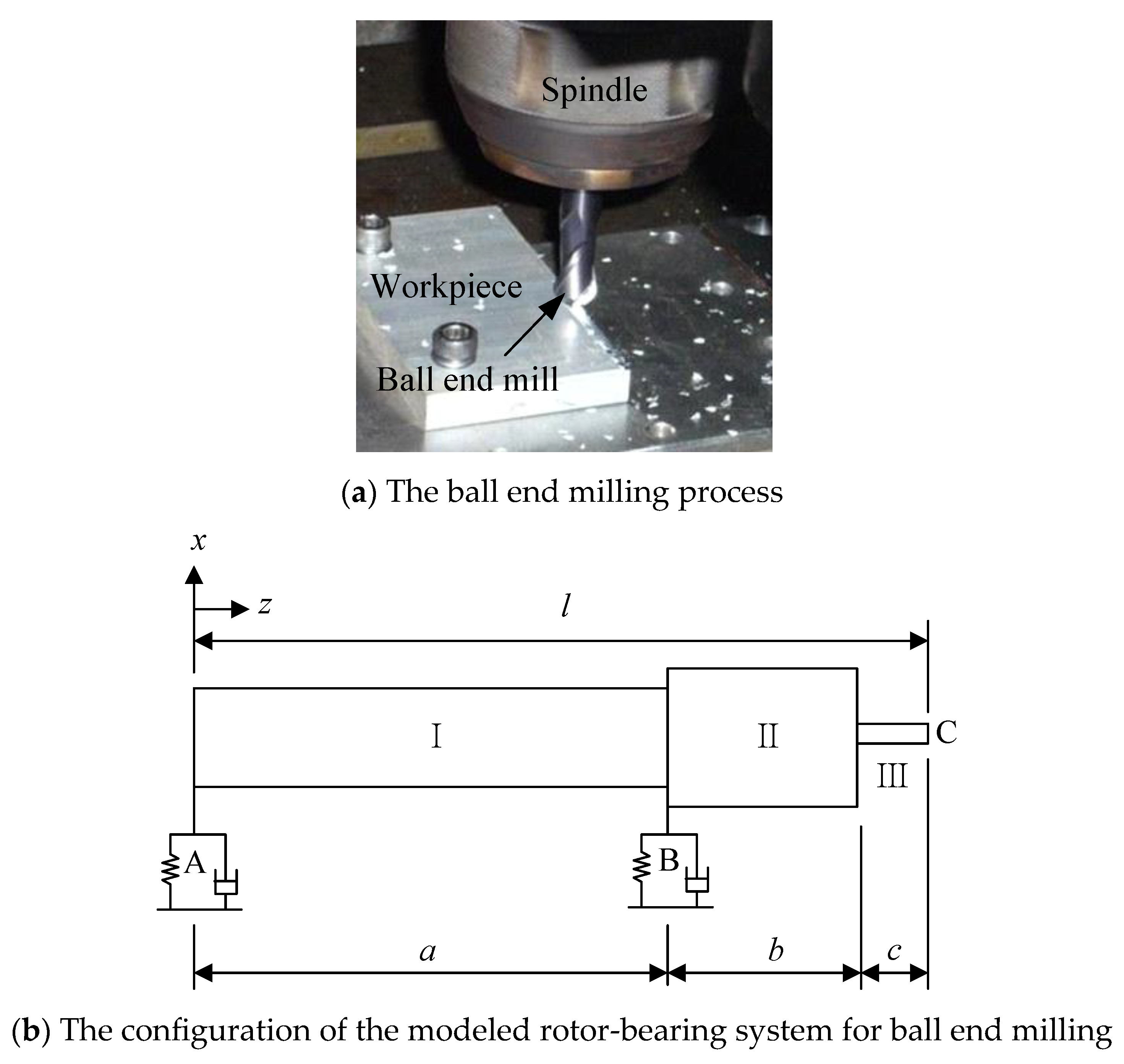
Figure 1. The tool spindle modeled as a rotor-bearing system.
Applsci 13 07252 g001
Figure 2. The geometry of a helical ball end mill.
Applsci 13 07252 g002
Figure 3. Cutting forces, chip thickness, and area of cutting segment in ball end milling.
Applsci 13 07252 g003
Figure 4. Natural frequency vs. spindle speed at various modes for flexible rotor system.
Applsci 13 07252 g004
Figure 5. The mode shapes for the rotor-bearing system at the critical speeds.
Applsci 13 07252 g005
Figure 6. Tool-tip response with 2 flutes at spindle speed of 1320 rpm.
Applsci 13 07252 g006
Figure 7. Response of tool-tip with 2 flutes at spindle speed of 6040 rpm.
Applsci 13 07252 g007
Figure 8. Tool-tip response with 2 flutes at spindle speed of 19,950 rpm.
Applsci 13 07252 g008aApplsci 13 07252 g008b
Figure 9. Tool-tip response with 3 flutes at spindle speed of 960 rpm.
Applsci 13 07252 g009
Figure 10. Tool-tip response with 3 flutes at spindle speed of 2160 rpm.
Applsci 13 07252 g010
Figure 11. Tool-tip response with 3 flutes at spindle speed of 4410 rpm.
Applsci 13 07252 g011aApplsci 13 07252 g011b
Figure 12. Tool-tip response with 3 flutes at spindle speed of 9850 rpm.
Applsci 13 07252 g012
Table 1. Cutting condition and cutting parameters.
Cutting Condition
Carbide Ball End Mills
Tool radius R 0 R3Workpiece material: Ti6Al4V Cutting coefficient
Shear stress    τ = 613 MPa
Friction angle    β = 19.1 + 0.29   α
Chip compression ratio   γ = p h q
p = 1.755 0.028   α , q = 0.331 0.0082   α
α : Rake angle, h : Chip thickness
Edge force coefficients:
K te = 24   N / mm , K re = 43   N / mm ,
K ae = 3   N / mm
Cutting force coefficients: given in Appendix C
Tool length c 30 mm
Axial depth of cut a ^ 1 mm
Feed per tooth f d 0.3 mm (2 flutes)
0.2 mm (3 flutes)
Rake angle α 5 °
Helix angle I 0 30 °
ρ = 1.45 × 10 5   kg / mm 3
E = 2.14 × 10 5   N / mm 2
N f = 2   and   3
Table 2. Configuration data of rotor-bearing system in Figure 1b.
Spindle SectionE (N/mm2)ρ (kg/mm3)do (mm)dI (mm)Length
I 2.14 × 10 5 7.833 × 10 6 10060 a = 216   mm
II 2.14 × 10 5 7.833 × 10 6 16060 b = 157   mm
III 2.14 × 10 5 1.45 × 10 5 60 c = 30   mm
Bearing A: K x x b = K y y b = 1.575 × 10   5   N / mm , C x x b = C y y b = 15.75   N s / mm , K x y b = K y x b = C x y b = C y x b = 0
Bearing B: K x x b = K y y b = 1.950 × 10   5   N / mm , C x x b = C y y b = 19.50   N s / mm , K x y b = K y x b = C x y b = C y x b = 0
Table 3. Critical speed vs. natural frequency for various modes.
ModeTypeFlutesNcr (rpm)fn (rad/s)
1Backward Mode21323277
3965303
Forward Mode219,9534179
32161679
2Backward Mode260401265
344121386
Forward Mode2--
398583097
Disclaimer/Publisher’s Note: The statements, opinions and data contained in all publications are solely those of the individual author(s) and contributor(s) and not of MDPI and/or the editor(s). MDPI and/or the editor(s) disclaim responsibility for any injury to people or property resulting from any ideas, methods, instructions or products referred to in the content.