Abstract
Developing high-speed rotating machines, such as microturbines, requires new solutions for bearing systems. Foil bearings are one of the fastest-growing high-speed bearing technologies. This article presents the results of experimental studies on foil bearings conducted on a test rig reflecting the operating conditions of the target machine. The tested bearings were therefore placed in a chamber filled with a low-boiling medium used as a working fluid in vapour microturbines. The experiments were carried out for several test cycles following a repeatable procedure. To carry out the tests under specific environmental conditions, a measurement cycle according to the developed test procedure and a temperature stabilization system for long-term measurements were proposed. The research involved determining the thermal characteristics of four foil bearing variants and assessing the impact of operating conditions on their wear. Additional research has shown that the operating characteristics are highly dependent not only on the materials and geometry of the bearing but also on the surface roughness of the mating parts. This study is part of ongoing work to select appropriate designs and material packages for foil bearings operating under conditions involving lubricating film formation and heat dissipation.
1. Introduction
The bearing system of any rotating machine is crucial in terms of the permissible speed and mechanical and thermal loads. Bearings also often determine the service life and reliability of a device. Bearing properties, therefore, have a decisive influence on the operating parameters of the entire machine. That is why much attention should be paid to these components of a rotating machine during the design, construction and operation stages.
Numerous types of bearings are currently available on the market, which can be customised to match the specific operating parameters of a rotating machine. With increasing target speed and temperature, the number of commercially available bearing systems decreases. Currently, the most used high-speed bearings are gas bearings [1], magnetic bearings [2,3] and high-precision rolling bearings [4,5]. Each bearing type has its own properties that make it suitable for specific applications. Unfortunately, at very high speeds (approx. 100,000 rpm) and high temperatures, the selection of ready-to-use bearings is very limited. Foil bearings, predominantly classified as gas bearings, perform excellently under such conditions. While they have been known for many decades, their rapid advancement in recent years has been made feasible by developing novel materials and unique structures. The history of foil bearings is also linked to the growing popularity of high-speed rotating machines such as microturbines and turboexpanders [6,7,8]. A lot of research and development work is currently being carried out on the application of foil bearings in aviation [9,10], small-scale cogeneration [11,12,13] and the automotive industry [14,15,16]. Well-designed foil bearings have many advantages, such as the absence of external lubrication, low friction losses, low noise and vibration levels, long service life, and the ability to operate at high speeds and temperatures [17].
Foil bearings typically function as aerodynamic bearings, but less often as hydrodynamic bearings, using the viscosity of the surrounding fluid to form a lubricating film, eliminating the need for additional complex lubrication systems. The design of foil bearings incorporates the use of both the top and bump foils, in addition to the journal and sleeve [18]. Such a foil bearing structure is shown in Figure 1. By employing compliant foils, the dynamic stability of rotors supported by foil bearings experiences a significant improvement. This is because the shape of the lubrication space adapts to the current operating conditions. At the same time, the poor damping properties of the lubrication film are compensated by the flexible foil structure (i.e., top foil and bump foils) [19,20,21].
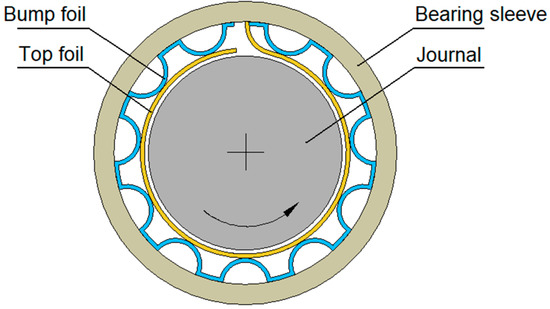
Figure 1.
The bump-type foil bearing design.
Many inventors have proposed numerous modifications of foil bearings, replacing standard bump foils with other structures with favourable static and dynamic properties. These include metal mesh foil bearings and hybrid bump-metal mesh foil bearings [22], gas foil bearings with metal shims between the bumps and the sleeve [23], foil bearings with an embedded compression spring [24] or foil bearings with embedded smart materials [25]. Hybrid (hydrodynamic and hydrostatic) foil bearings [26] and multi-layer protuberant foil bearings [27] have also been developed. Certain arrangements of foil bearings employ diverse cooling methods, including cooling fans [28], side-feed pressurisation [8] or the utilisation of thermocouples [29].
Foil bearings are typically gas lubricated to operate at very high rotational speeds with low frictional losses. A less popular method of lubricating foil bearings is the use of liquids. Bearings lubricated in this manner do not reach as high rotational speeds as gas foil bearings, but they have many other advantages. Lubricating the bearing with a liquid increases the load capacity. It allows direct use of process media, which in some machines (such as pumps) are present in liquid form, broadening the range of applications. Liquid-lubricated foil bearings, like aerodynamic gas bearings, do not need an external supply because they use fluids from their surroundings. An example of such bearings is the liquid hydrogen-lubricated foil leaf bearings presented in the work [30]. They were developed for a cryogenic turbopump to increase its service life, where they replaced the rolling bearings previously used. The conducted research confirmed the high load capacity and low frictional losses, as well as the excellent dynamic properties of the rotor supported by such bearings. The tested foil bearings also showed no measurable wear after 130 start/stop cycles. Examples of leaf-type foil bearings lubricated with liquid hydrogen and oxygen can also be found in work [31]. The advantages of using bump-type foil bearings in cryogenic turbopumps are presented in the work [32]. The authors of this publication demonstrated that the use of a lubricating medium in liquid form in foil bearings allows a threefold increase in load capacity while maintaining very good dynamic properties even at high rotational speeds. On the other hand, the work [33] presents a method of modelling and analysing leaf-type foil bearings lubricated with liquid nitrogen, which uses the finite element method and the Navier–Stokes equations, considering the properties of the actual lubricating medium. The work [34] presents a numerical model of a foil bearing lubricated with a gaseous and liquid low-viscosity lubricant. As advantages of such a solution, the authors pointed out the low frictional losses (the possibility of improving the efficiency of the machine), the elimination of dynamic seals, the reduction of the size of the bearing and the simplification of the design and the possibility of encapsulating the entire machine. As an example of using foil bearings lubricated with a low-boiling liquid medium, they presented the rotor of an energy microturbine. Modelling of foil bearings lubricated with liquid and gaseous refrigerant is also discussed in the work [35]. The proposed model describes the vapour/liquid transition and local thermal approach and makes it possible to determine the three-dimensional temperature distribution within the lubrication gap. The results obtained confirm the broad applicability of foil bearings, also in turbomachines used in refrigeration. Foil bearings can also be lubricated with water. Olszewski et al. published an experimental study on a prototype of this bearing type [36]. Utilising water as a lubricant for foil bearings enables the development of environmentally friendly machines such as hydroelectric turbines and water pumps. The initial findings from the research on water-lubricated foil bearings demonstrated an exceptionally low coefficient of friction (approximately 0.01) and a load capacity of about 300 kPa [36].
The examples of foil bearing design solutions presented above and the utilisation of diverse lubricants contribute to the multidirectional development of this bearing technology. A comprehensive wide state-of-the-art overview of the development of foil bearing technology can be found in several publications [7,37]. Various modelling methods [18,19,23,24] and experimental research [22,23,24,26] of foil bearings are described in available publications. Although the dynamic properties of rotating systems can be predicted quite accurately using advanced foil bearing modelling techniques [19,23,38], numerical models cannot accurately assess tribological properties and bearing life. In this regard, experimental research is required.
This article describes an experimental study aimed at determining the thermal properties and wear behaviour of foil bearings made of various materials, depending on bearing geometry, surface roughness, lubrication and cooling conditions. For this purpose, start/stop tests were performed according to a well-defined procedure. Conducting research in the form of several start/stop tests not only allows us to determine the service life of foil bearings but also allows us to determine their basic operating parameters. During machine start-up and run-down, the rise in foil bearing torque results from a lubricating film formation and loss at low rotor journal speeds, as well as the initial clumping (mechanical preload) of the top foil on the journal. In our study, we established a correlation between the thermal characteristics of the tested bearing variants, their design and the quality of the mating surfaces. The experimental test rig used allows for conducting start/stop tests in the presence of any fluids, such as low-boiling liquids used in vapour microturbines [12,13,39,40]. In this context, the research presented in this article is a significant novelty, since the experimental studies on foil bearings presented in other publications were mostly conducted under gas or other liquid lubrication conditions. Until now, there have been no published experimental studies investigating the use of a liquid low-boiling medium as a lubricant for foil bearings.
The research findings presented in the following sections enabled us to evaluate the usefulness of the developed liquid-lubricated foil bearings and determine the selected operating characteristics. The research methodology presented and the results obtained may be useful to other foil bearing researchers and designers by providing insight into the operation of such bearings under unusual lubrication conditions.
2. Materials and Methods
2.1. Object of Investigation
The object of investigation was the first-generation foil bearing, whose structure is shown in Figure 2. The foil assembly consisted of one top foil and one bump foil. One end of both foils (0.1 mm thick) was fixed in a narrow groove (0.3 mm wide), which can be seen at the top of the hole in the bearing sleeve. The nominal diameter of the bearing, which was equal to the diameter of the journal, was 25 mm, and the length of the bearing was 40 mm. Tests were performed on two geometric variants of the bearing where different assembly preloads were achieved. Various materials were also considered during the study. The top foil was made of brass (2.0321) or a copper alloy (CuAl7). The bump foil was made of the same copper alloy (CuAl7) or an Inconel alloy. Two material variants were thus created for the bearings: a brass top foil in combination with a bump foil made of a copper alloy, or a top foil made of a copper alloy in combination with an Inconel foil. Four bearing variants (two geometric variants and two material variants) were subjected to tests. The basic technical parameters of the tested bearings are shown in Table 1.
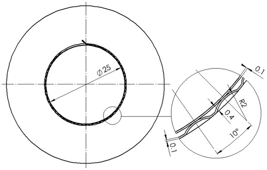
Figure 2.
Geometry and basic dimensions of the tested foil bearing.

Table 1.
Main technical data of the tested foil bearing.
The tested bearings were developed for use in vapour microturbines whose power ranges from 1 to 30 kW. Such microturbines typically use a low-boiling working fluid whose boiling point is lower than water’s. This allows the thermodynamic cycle to operate efficiently at much lower temperatures and use low- and medium-temperature waste heat sources. Therefore, a low-boiling liquid with a trade name of HFE-7100 was used as a bearing lubricant. It is a colourless, non-flammable, dielectric fluid with low global warming potential (GWP) and zero ozone depletion potential (ODP). At a temperature of 25 °C, the HFE-7100 fluid exhibits a density of 1.5 g/cm3 and a dynamic viscosity of 0.57 mPa·s. At atmospheric pressure, it has a boiling point of 61 °C. During the tests, the foil bearing was lubricated with this low-boiling medium in liquid form. Therefore, these were not typical operating conditions for foil bearings.
2.2. Description of the Test Rig
Experimental tests were carried out using a test rig capable of determining the operating characteristics of foil bearings lubricated by any working fluid, including low-boiling liquids. Figure 3 shows the test rig consisting of the following systems:
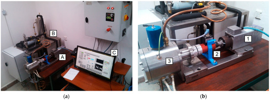
Figure 3.
Test rig for testing foil bearings lubricated by any working fluid: (a) general view of the test rig; (b) drive system with a measuring chamber.
As shown in Figure 3b, the driving torque is transmitted from the electrospindle (1) to the measuring chamber (3) via the torque meter (2) and the flexible coupling. The test rig was placed on a common steel frame. The diagram of the measuring chamber showing how the foil bearing is attached, and the arrangement of the individual subassemblies is shown in Figure 4. The ram of the electromagnetic servomotor is used to load the test bearing, although it was not utilised in the study in question. This part of the test rig served the sole purpose of restricting the rotations of the bearing sleeve. The bearing was statically loaded with only the bearing sleeve, which had a weight of 96 g. During the tests, the measuring chamber was filled with a low-boiling liquid, so the entire bearing was immersed. The heaters shown in the diagram were not used in these tests. The presented configuration of the test rig allows us to conduct start/stop tests in automatic mode (according to a predetermined schedule).
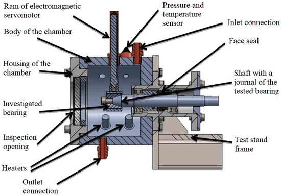
Figure 4.
Diagram of the measuring chamber with a description of the most important subassemblies.
Several parameters were measured during the tests to evaluate the operational characteristics of the foil bearing. Torque and rotational speed were measured using a KTR DATAFLEX 10/16 torque sensor with a measurement range of −10 to +10 Nm and a measurement error of less than 0.1%. The same torque sensor can measure speeds up to 10,000 rpm. Class 1 thermocouples (TP-201 and TP-202) were used to measure temperature with their tips placed inside the measuring chamber. In addition, the temperature distribution was monitored with a FLIR T365 thermal imaging camera, which has a thermal sensitivity (NETD) of less than 0.05 °C at a target temperature of 30 °C. The measurement results were collected and archived by a single common data acquisition system and displayed in real time on the monitor shown in Figure 3a.
2.3. Experimental Procedure
Start/stop tests concerning foil bearings are important because the main reason for the foil bearing wear is the friction between working parts of the bearing, mainly between the top foil and the shaft journal, occurring during the start-up and run-down of the rotating machine and at the instantaneous bearing overloads. Studies into foil bearings in a start/stop cycle allow determining the durability of wear parts of the bearing, especially top and bump foils, as well as journal [41,42,43].
To carry out the experiments in conditions close to real and to maintain quasi-stable conditions in the measuring chamber, an attempt was made to stabilize the temperature around the test chamber. During the tests in the start/stop cycle in the measuring chamber, the temperature of the medium increases under the influence of friction of the shaft journal against the top foil and the ball bearing mounted in the housing (Figure 5).
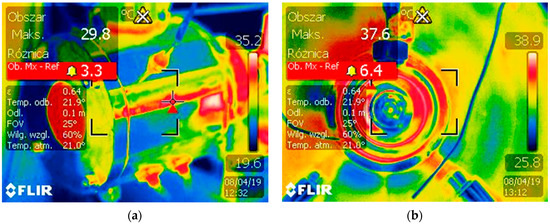
Figure 5.
Pictures taken by a thermal imaging camera: (a) View of the outer surface of the chamber; (b) View from the front of the chamber on the bearing (this picture was taken without a glass in the inspection opening).
To stabilize the temperature inside the test chamber during the measurement cycles without the use of specialized heat generation systems (e.g., Peltier cells), it was decided to use forced air convection around the measuring chamber. For this purpose, a prepared exhaust hood was used, directing a stream of previously sucked air to the chamber from the same room as the test stand. The outlet of the flexible pipe was directed to the measurement chamber (Figure 6) so that the air stream was blowing the chamber from the side of the low-boiling medium and the ball-bearing block. During the test cycle, the exhaust extractor operated at a constant capacity of 870 m3/h.
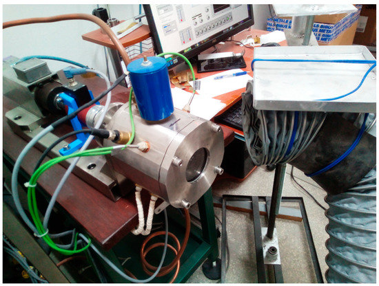
Figure 6.
Prepared cooling system of the measuring chamber.
To determine the temperature rise curve as a function of the number of test cycles, preliminary measurements were carried out for 200 cycles, according to one predetermined time interval, for four geometrical and material variants of the foil bearing. The operating cycle of the foil bearing on the test stand was carried out in the automatic mode (Figure 7) for the sequence run-up-work-coast-down-break (Tr = 3 [s], Tp = 3 [s], Tw = 3 [s], Tn = 10 [s]). The maximum rotational speed of the bearing journal was 7500 rpm. The above-mentioned study will allow estimating the dynamics of temperature increase in the measuring chamber.
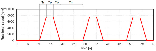
Figure 7.
Course of rotational speed changes during the test cycle: Tc—cycle duration, Tr—run-up time, Tp—work time, Tw—run-down time, Tn—pause time.
Two thermocouples are installed in the measuring chamber, which enables the temperature of the medium inside the chamber and the foil bearing housing to be measured. Based on the comparison, it can be concluded that the maximum difference in their indications did not exceed 0.5 °C. The results of the experimental investigation are presented in the next section of the article.
3. Results and Discussion
3.1. Temperature Measurements
Figure 8, Figure 9, Figure 10, Figure 11 and Figure 12 show the results of temperature measurements using thermocouples placed in the measuring chamber. The temperature rise curves in the test chamber for one bearing housing diameter (25.9 mm), with cooling taken into account, are presented in Figure 8. In the case of the CuAl7/Inconel material pair (top/bump foils), the most significant differences can be seen at the 200th cycle. The use of cooling slows down the temperature rise in the chamber, so it is possible to obtain quasi-stable conditions in the test chamber without boiling the working medium used as a lubricating liquid.
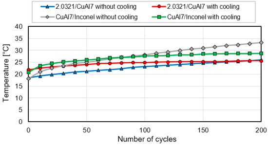
Figure 8.
Graph of temperature changes in the test chamber for 200 cycles for a housing diameter of 25.9 mm for material pairs 2.0321/CuAl7 and CuAl7/Inconel with the use of cooling.
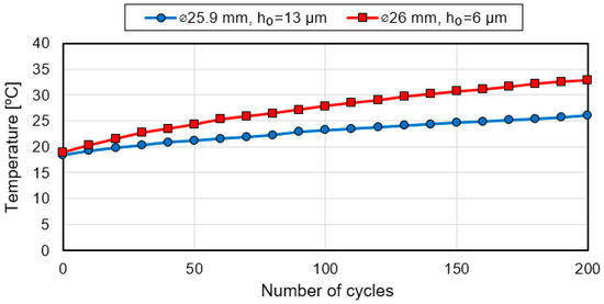
Figure 9.
Temperature rise curve for material pair 2.0321/CuAl7 (top/bump foils) without cooling system for two bearing housing diameters.
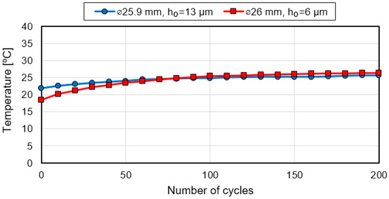
Figure 10.
Temperature rise curve for material pair 2.0321/CuAl7 (top/bump foils) when using a cooling system for two bearing housing diameters.
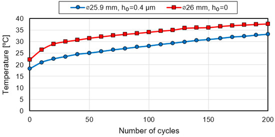
Figure 11.
Temperature rise curve for CuAl7/Inconel material pair (top/bump foils) without a cooling system for two bearing housing diameters.
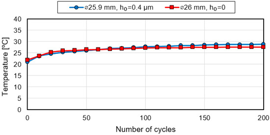
Figure 12.
Temperature rise curve for CuAl7/Inconel material pair (top/bump foils) with a cooling system for two bearing housing diameters.
When analysing the temperature rise curves for the material pair 2.0321/CuAl7, in the absence of cooling, the characteristic takes a steadily increasing course (Figure 8). Since two test modes were carried out directly, one after another, the thermal inertia of the system after the first test mode increased the temperature in the chamber. However, the subsequent course of the characteristics already proves the effectiveness of the cooling system. This was manifested by stabilizing the temperature in subsequent cycles. More cycles would reveal the resulting temperature differences.
By comparing the temperature rise curves in the test chamber for two different bearing housing diameters (25.9 mm and 26 mm), which were also characterised by different bearing clearance (h0), for two selected material pairs and the cooling capacity of the chamber, visible differences can be observed. Figure 9 clearly shows that the temperature in the bearing with the larger diameter sleeve increased more. However, attention should be paid to the fact that the bearing clearance was lower in the case of the bearing with a larger diameter, which is discussed in detail in the next section of the article. After 200 start/stop cycles, the temperature was 32.9 °C for the bearing with the 26 mm inner diameter sleeve and 26.1 °C for the bearing with the 25.9 mm inner diameter sleeve. The higher temperature rise for the bearing with the larger diameter sleeve can be attributed to different assembly preloads and structural stiffness due not only to the inner diameter of the sleeve but also to the geometry of the top and bump foils and surface roughness. The technology manufacturing bump foils are typically characterised by poor repeatability [44,45]. It is affected, among other things, by elastic and plastic deformation of thin metal sheets. As a result, there may be certain deviations in the dimensions and shape of the foils. To clarify this, additional tests were conducted to determine the actual clearance or assembly preload of the tested bearings. The course of this research and its outcomes will be discussed in the following section of the article.
After using an additional external cooling system, the temperatures of the two bearings with foils made from the material combination 2.0321/CuAl7 stabilised at a similar level (Figure 10). At the end of the test, the bearing with the 25.9 mm inner diameter sleeve reached a temperature of 25.6 °C and the bearing with a larger diameter reached a temperature of 26.3 °C. The temperature difference was only 0.7 °C. A slight increase in temperature in both bearings over the last few test cycles indicated that the bearing node was approaching thermal equilibrium.
The use of a cooling system had a positive effect on stabilizing the temperature rise. This was also the case for the second material variant of the foil bearing. This can be seen in the graphs obtained for the bearings whose foils were made of the CuAl7/Inconel material combination. When the cooling system was not activated, the temperature rose almost linearly to 37.7 °C for the bearing with a larger sleeve and 33.2 °C for the other bearing (see Figure 11). Activating the cooling system resulted in the reduction of the bearing temperature to approximately the same level (see Figure 12). With the cooling system, the temperature difference obtained after 200 start/stop cycles was only 1.1 °C, while without the cooling system, it was 4.5 °C (after 200 start/stop cycles). The beneficial effect of external cooling on the operation of the foil bearing was therefore confirmed. An increased number of start/stop cycles would increase this temperature difference due to the additional phase change of the low-boiling medium.
The measurement results obtained for the second pair of materials also confirmed the necessity for additional research. A greater temperature increase in the bearing with a larger diameter sleeve was unexpected, as theoretically, there should have been a lower assembly preload in this bearing which should have resulted in less heat generation during operation. Therefore, the tested material and geometric variants were further investigated, as discussed in the following part of the article.
3.2. Measurements of Mechanical Properties
To clarify the reason for the greater temperature rise during the operation of the foil bearing with a larger sleeve diameter, additional experimental research was carried out. The purpose of this research was to determine the actual clearance or assembly preload of the bearings tested. The foil bearing test method is often used in practice [22,46,47], as it allows the clearance/preload to be determined directly and the different foil bearings to be compared objectively without having any information on the manufacturing accuracy of their components. Structural stiffness tests were carried out on the test rig shown in Figure 13 and measured the displacement of a bearing sleeve subjected to a static load. As sleeve displacements were expected to be very small, a precision optical displacement sensor (Keyence LK-H050, Keyence, Itasca, IL, USA) with a 10 mm measurement range and 0.02% measurement linearity was used. This sensor was connected to a central unit (Keyence LK-G5001P, Keyence, Itasca, IL, USA). The bearing static load consisted of a stack of steel weights of different weights. The loading system was connected to the foil bearing sleeve via a force sensor (KMM30-200N, Wobit, Pniewy, Poland) with a measuring range of 200 N and a linearity tolerance of 0.2%. A data acquisition and real-time control system (Dewesoft IO-LITE, Dewesoft, Whitehouse, OH, USA) with a six-channel analogue amplifier (6xSTG) was used for data acquisition and processing. The actual bearing load and bearing sleeve displacement were recorded simultaneously and presented on the display in real time.
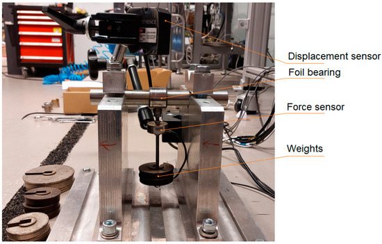
Figure 13.
Test rig used to determine the structural stiffness of foil bearings.
Structural stiffness tests of foil bearings were performed with a maximum static load of approximately 10 N. This load value was chosen due to the small diameter and load capacity of the bearing. It is worth mentioning that during the tests discussed in the earlier section, the foil bearing was statically loaded with only the weight of the sleeve, which is only 96 g. In addition to the loading system with appropriately selected weights, the bearing was continuously loaded with a force sensor weighing 78 g during static stiffness tests (Figure 14). With this sensor, it was possible to record the actual load acting on the bearing. Due to the complementary nature of the research in question, the structural stiffness was only determined in one direction, allowing different material and geometrical configurations of the foil bearing to be compared.
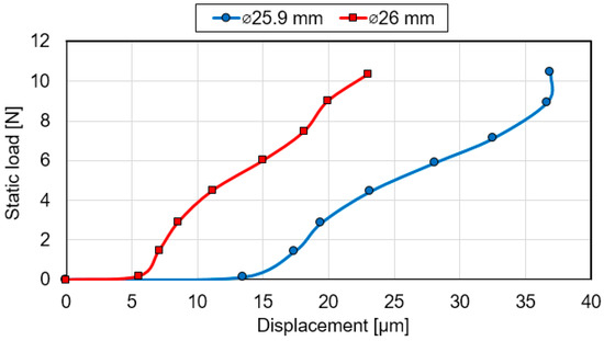
Figure 14.
Comparison of structural stiffness curves obtained for two foil bearings with sleeves of different diameters and top and bump foil made from the material combination 2.0321/CuAl7.
The measurement results of the displacement versus the acting static load are shown in Figure 14 and Figure 15. Figure 14 shows a comparison of the structural stiffness of the bearing with foils made from the material combination 2.0321/CuAl7. From the obtained characteristics, the bearing with a larger sleeve diameter (26 mm) had higher stiffness. The measured bearing clearance was about 6 µm, while the clearance of the bearing with a sleeve diameter of 25.9 mm, which was estimated in the same way, was about 13 µm. The further course of the structural stiffness of the two bearings was similar. Still, the characteristic obtained for the bearing with a smaller sleeve diameter was shifted to the right by a value close to the difference in the initial clearance.
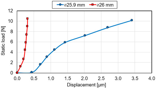
Figure 15.
Comparison of structural stiffness curves obtained for two foil bearings with sleeves of different diameters and top and bump foil made from the material combination CuAl7/Inconel.
Different static stiffness waveforms were obtained for the bearing with foils made of CuAl7/Inconel materials (Figure 15). For the bearing with the smaller sleeve diameter (25.9 mm), an initial clearance of about 0.4 µm was recorded, and the maximum displacement at the highest load of approximately 10 N was only 3.4 µm. The bearing with a sleeve diameter of 26 mm featured even higher stiffness. In this case, no initial clearance was recorded because the initial load did not cause the sleeve to move. This means that in this bearing variant, there is the initial clamping of the foil on the journal, and a load had to be applied to achieve even a small displacement. It is worth noting that the assembly of the bearing with a bump foil made of Inconel was very difficult (the considerable force was required to move this foil in the sleeve hole during assembly), which may be indicative of the high friction coefficient for the Inconel/steel 1.0562 material pair. It was also noted that the bump foil made of Inconel had a higher stiffness than the bump foil made of a copper-aluminium alloy (CuAl7), which made it difficult to match the shape of the Inconel foil to the sleeve hole during bearing assembly. These factors may have been the reason that the clearance values obtained for the second material variant of the foil bearing (CuAl7/Inconel) were significantly lower than those obtained for the first material variant of the bearing (2.0321/CuAl7), despite using the same sleeves.
The results of the static stiffness tests discussed above were, on the one hand, surprising. On the other hand, they allowed us to explain the reasons for obtaining the unexpected thermal characteristics discussed in Section 3.1. Without external cooling, foil bearings with sleeves whose inner hole diameters were larger heated up to a higher temperature than foil bearings with sleeves of a smaller diameter. Foil bearings with sleeves of a smaller diameter should feature a tighter fit, so more heat should be generated when the journal rotates. However, as the studies discussed in this chapter have shown, smaller diameter bearings provided less support stiffness and a looser fit, which explains the generation of less heat in the bearing node.
To unambiguously explain the reason for the higher structural stiffness of foil bearings with larger diameter sleeves, an attempt was made to indicate the source of this anomaly. A detailed visual inspection of the used bearing sleeves revealed that the differences in the characteristics of the tested bearings could be attributed to the manufacturing quality of the inner surface of the sleeves. This surface is crucial for the correct operation of the foil bearing, as it mates with the bump foil, which in turn supports the top foil. To objectively assess the quality of these surfaces, roughness measurements were carried out using a device (FTA H4D4000-D, Mitutoyo Corporation, Aurora, CO, USA) produced by Mitutoyo Corporation. The method of carrying out roughness measurements is shown in Figure 16.
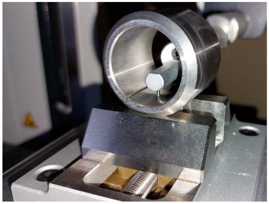
Figure 16.
Measurement of the roughness of the inner surface of the foil bearing sleeve.
Roughness measurements were conducted three times at different circumferential locations within the hole of each sleeve. The measurements showed that the inner surface roughness (Ra) of the sleeve with a diameter of 25.9 mm was 0.526, 0.530 and 0.541 µm. The average value of the roughness (Ra) was, therefore, 0.532 µm. The following roughness (Ra) values were obtained for the sleeve with an orifice diameter of 26 mm: 0.644, 0.744 and 0.709 µm. The average value of the roughness (Ra) was, therefore, 0.699 µm and was 31% higher than that obtained for the sleeve with a smaller diameter. The differences in surface roughness were due to the treatment method used. The holes in both sleeves were initially made to have a diameter of 25.9 mm. Only in the second stage, the hole in one sleeve was enlarged to a diameter of 26 mm by mechanical working. A material allowance of 0.1 mm (around the circumference) proved insufficient to achieve good machining parameters and maintain the original surface roughness.
Based on the additional tests performed, it was concluded that the quality of the inner surface of the bearing sleeves could be of great importance for the static and operational characteristics of the tested foil bearings. This surface supports the foil assembly and directly connects with the bump foil. It turns out that if the roughness of this surface is too large, the bump foil can have difficulty sliding over it, and its restricted movement increases the structural stiffness of the entire foil bearing. The influence of surface roughness on the stiffness of foil bearings and their operational characteristics has already been noted by other researchers [48,49,50]. In the case in question, an increase of more than 30 per cent in the surface roughness of the bearing sleeve could have had a greater impact on the bearing characteristics than a 0.1 mm change in the mounting hole diameter. This is an important observation from the research conducted, which draws attention to the manufacturing accuracy and quality of the mating surfaces of foil bearings.
3.3. Wear Measurements
Since the shaft journal is in direct contact with the top foil during low-speed operation of the foil bearing, wear occurs under these conditions. To accurately assess the wear of materials in the tested bearings, in addition to the visual assessment of the sliding surfaces, precise weight measurements of the wearing parts were performed. An analytical balance RADWAG AS 60/220.R2 was used for precise mass measurement, enabling measurement with an accuracy of 0.00001 g. The results of these measurements are discussed in this section.
Based on the measurements presented in Table 2 and Table 3, it can be concluded that the loss of foil weight depended on bearing sleeve diameter, surface roughness (which collectively determine assembly preload and structural stiffness) and the cooling conditions. For the first pair of materials (2.0321/CuAl7), the weight loss of the top foil was much smaller (from several to several dozen times). For bump foils, it depended on the specific conditions. In the case of the first pair of materials (2.0321/CuAl7), the cooling influence on the top foil’s wear was also much smaller than for the second pair of materials (CuAl7/Inconel). In the case of a bearing with a smaller clearance (bearing housing diameter of 25.9 mm) for the first variant of materials, the effect of cooling on the wear of this foil was not noticed. The cooling effect was more visible for the second variant of materials (CuAl7/Inconel). The use of external cooling reduced the weight loss of the top foil by about two times. Bump foil wear was random, with no clear trend to draw more general conclusions. This could be because the bump foil wears in many places simultaneously, both on the top foil side and on the side of the housing. The wear of these foils can largely depend on local operating conditions.
Table 2.
Mass consumption of individual foils after 200 measurement cycles in various cooling conditions for a bearing housing diameter of 26 mm.
Table 3.
Mass consumption of individual foils after 200 measurement cycles in various cooling conditions for a bearing housing diameter of 25.9 mm.
Comparing the values of the mass consumption of individual foils, one can see the increased mass consumption of the CuAl7/Inconel material pair. The reduction in bearing clearance due to the reduction in the diameter of the bearing housing and the use of thicker Inconel foil results in both increased frictional heat generation and increased mass wear. The maximum consumption of the CuAl7 top foil (most exposed to friction of the rotating journal) is 0.00226 g for the CuAl7/Inconel material pair (top/bump foil).
Figure 17 shows a view of the foils used in the tests for the CuAl7/Inconel material pair. The mating surfaces of the top foil and the shaft journal after 200 cycles of sequential start/stop work are visible. Figure 17a shows the surface condition after testing without additional cooling, and Figure 17b after applying external cooling. The consumption is not uniformly distributed. After the predetermined number of test cycles, wear of the shaft journal was not observed.
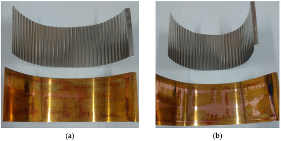
Figure 17.
Technical condition of the sliding surface of the top and bump foils: (a) after 200 cycles without cooling; (b) after 200 cycles with cooling.
When analysing the course of the moments of resistance to motion in the foil bearing for the CuAl7/Inconel material pair at the beginning and the end of the measurement cycle, no apparent differences in the indications of the measuring device were found (Figure 18). Therefore, a comparison of the results obtained before and after 200 start/stop cycles can only be of qualitative and not quantitative nature, without analysing the exact values. To make more accurate torque measurements, changes would need to be made to the test rig design, including contactless seals and rolling bearings with reduced torque, etc. Based on the rough measurement of the torque, it can be concluded that the 200-cycle test using the time interval settings: run-up-work-coast-down-break (Tr = 3 [s], Tp = 3 [s], Tw = 3 [s], Tn = 10 [s]) is not reliable from the point of carrying out the long-term tests, but it is an excellent signal and determinant of the benefits of using the proposed cooling system.
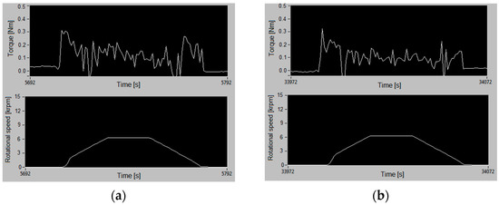
Figure 18.
Resistance torque distribution for the CuAl7/Inconel material pair: (a) at the beginning of the test; (b) after 200 start/stop cycles.
4. Conclusions
This article focuses on presenting the changes in temperature rise depending on different foil bearing designs and materials, the use of the test chamber cooling system and the different number of cycles. The experimental tests of the foil bearing were carried out in a special measuring chamber in which the conditions prevalent in a vapour microturbine fed with a low-boiling medium were simulated. Multi-cycle research (implementing run-up, constant speed running and run-down phases while maintaining the stability of the operating conditions) provides answers to many very important questions regarding the characteristics of top and bump foils under different load conditions or different states of aggregation of the low-boiling medium that has been used as a lubricant. Research shows that changing bearing clearance and assembly preload significantly affects heat generation and foil wear. A comparison of foil wear results obtained for the same material pair with diameters of 25.9 mm and 26 mm with different surface roughness shows that wear increases as the bearing clearance decreases. The maximum weight loss value of the top foil made of CuAl7 for a bearing housing diameter of 25.9 mm is 0.00226 g, while for a bearing housing diameter of 26 mm, it is 0.00088 g.
A crucial finding of the conducted study was the demonstration of a very large effect of the sleeve’s surface roughness on both the structural and operational characteristics of the entire foil bearing. The increase in roughness (Ra) from 0.532 µm to 0.699 µm could have resulted in a significant increase in structural stiffness, consequently resulting in an elevation of the bearing’s operating temperature. The obtained results showed that this thread requires further analysis and regular experimental research to thoroughly investigate the effect of the surface roughness of the part of the foil bearing on its characteristics.
The proposed cooling system fulfils its role when the temperature in the measuring chamber rises sharply due to the reduced bearing clearance. The temperature in the chamber stabilizes at the level at which the low-boiling medium maintains its state of aggregation. For the bearings with foils made from the material combination 2.0321/CuAl7, the maximum temperature at the end of the test with cooling applied was about 26.3 °C. Without external cooling, this temperature was 32.9 °C. In the case of the second material combination (CuAl7/Inconel), the temperature reached a value of 37.7 °C during the test without cooling. However, with the application of cooling, the maximum temperature dropped below 30 °C. Therefore, it was possible to carry out the test procedure in a start/stop cycle under quasi-steady conditions in the test chamber.
The analysis of the actual friction torque curve of the foil bearings over 200 test cycles showed no significant changes or disturbances. On the one hand, the bearing parts wore out during the tests, which is also the effect of the running-in process.
After conducting a series of experiments, it was also found that the 200-cycle tests only partially used the possibilities and research potential of the multi-repetition test. However, it is a good source of new knowledge about the actual properties of foil bearings. Therefore, the tests described in the article will be continued.
Author Contributions
Conceptualization, W.M.; methodology, W.M. and B.M.; software, B.M. and W.K.; validation, B.M., G.Ż. and W.K.; investigation, B.M., P.B. and W.M.; resources, W.M. and B.M.; data curation, B.M., W.K., P.B. and G.Ż.; writing—original draft preparation, B.M., W.M. and G.Ż.; writing—review and editing, G.Ż. and W.M.; visualisation, B.M. and G.Ż.; supervision, W.M.; project administration, W.M.; funding acquisition, W.M. All authors have read and agreed to the published version of the manuscript.
Funding
This research was funded by the Innovative Economy Operational Programme 2007–2013 and co-funded by the European Union using financial funds of the European Regional Development Fund, grant number POIG.01.03.01-00-027/08 entitled: “Using intelligent materials and structures to develop and implement the concept of the innovative bearing system in power microturbine rotors”.
Institutional Review Board Statement
Not applicable.
Informed Consent Statement
Not applicable.
Data Availability Statement
Data available on request. The data presented in this study are available on request from the corresponding author.
Conflicts of Interest
The authors declare no conflict of interest.
References
- Gu, L.L.; Guenat, E.; Schiffmann, J. A Review of grooved dynamic gas bearings. Appl. Mech. Rev. 2020, 72, 010802. [Google Scholar] [CrossRef]
- Supreeth, D.K.; Bekinal, S.I.; Chandranna, S.R.; Doddamani, M. A review of superconducting magnetic bearings and their application. IEEE Trans. Appl. Supercond. 2022, 32, 3800215. [Google Scholar] [CrossRef]
- Samanta, P.; Hirani, H. On the evolution of passive magnetic bearings. J. Tribol. 2022, 144, 040801. [Google Scholar] [CrossRef]
- Sharma, A.; Upadhyay, N.; Kankar, P.K.; Amamath, M. Nonlinear dynamic investigations on rolling element bearings: A review. Adv. Mech. Eng. 2018, 10, 1–15. [Google Scholar] [CrossRef]
- Smith, W.A.; Randall, R.B. Rolling element bearing diagnostics using the Case Western Reserve University data: A benchmark study. Mech. Syst. Signal Process. 2015, 64–65, 100–131. [Google Scholar] [CrossRef]
- Walton, J.F.; Hesmat, H. Application of foil bearings to turbomachinery including vertical operation. J. Eng. Gas Turbines Power 2002, 124, 1032–1041. [Google Scholar] [CrossRef]
- Samanta, P.; Murmu, N.C.; Khonsari, M.M. The evolution of foil bearing technology. Tribol. Int. 2019, 135, 305–323. [Google Scholar] [CrossRef]
- Hoffmann, H.; Pronobis, T.; Liebich, R. Stability analysis of pressurized gas foil bearings for high speed applications. In Proceedings of the 11th International Conference on Turbochargers and Turbocharging, London, UK, 13–14 May 2014. [Google Scholar]
- De Santiago, O.; San Andres, L. Parametric study of bump foil gas bearings for industrial applications. In Proceedings of the ASME Turbo Expo, Vancouver, BC, Canada, 6–10 June 2011; Volume 6, pp. 445–456. [Google Scholar]
- Kumar, J.; Khamari, D.S.; Behera, S.K.; Sahoo, R.K. A review of thermohydrodynamic aspects of gas foil bearings. Proc. Inst. Mech. Eng. Part J-J. Eng. Tribol. 2022, 236, 1466–1490. [Google Scholar] [CrossRef]
- Kozanecki, Z.; Tkacz, E.; Lagodzinski, J.; Miazga, K. Oil-free bearings for hermetic high-speed turbomachinery. J. Vib. Eng. Technol. 2014, 2, 351–360. [Google Scholar]
- Zywica, G.; Kaczmarczyk, T.Z.; Brenkacz, L.; Bogulicz, M.; Andrearczyk, A.; Baginski, P. Investigation of dynamic properties of the microturbine with a maximum rotational speed of 120 krpm—Predictions and experimental tests. J. Vibroeng. 2020, 22, 298–312. [Google Scholar] [CrossRef]
- Kicinski, J. The dynamics of microturbines lubricated using unconventional agents. Bull. Pol. Acad. Sci. Tech. Sci. 2015, 63, 369–377. [Google Scholar] [CrossRef]
- San Andres, L.; Ryu, K.; Diemer, P. Prediction of gas thrust foil bearing performance for oil-free automotive turbochargers. J. Eng. Gas Turbines Power 2015, 137, 032502. [Google Scholar] [CrossRef]
- Sim, K.; Lee, Y.B.; Kim, T.H. Rotordynamic analysis of an oil-free turbocharger supported on lobed gas foil bearings-predictions versus test data. Tribol. Trans. 2014, 57, 1086–1095. [Google Scholar] [CrossRef]
- Ryu, K.; Ashton, Z. Oil-Free Automotive Turbochargers: Drag Friction and On-Engine Performance Comparisons to Oil-Lubricated Commercial Turbochargers. J. Eng. Gas Turbines Power 2017, 139, 032301. [Google Scholar] [CrossRef]
- Dellacorte, C.; Lukaszewicz, V.; Valco, M.J.; Radil, K.C.; Heshmat, H. Performance and durability of high temperature foil air bearings for oil-free turbomachinery. Tribol. Trans. 2000, 43, 774–780. [Google Scholar] [CrossRef]
- Daejong, K.; Soongook, P. Hydrostatic air foil bearings: Analytical and experimental investigation. Tribol. Int. 2009, 42, 413–425. [Google Scholar] [CrossRef]
- Howard, S.A.; San Andres, L. A new analysis tool assessment for rotordynamic modeling of gas foil bearings. J. Eng. Gas Turbines Power 2011, 133, 022505. [Google Scholar] [CrossRef]
- Kulkarni, S.; Naik, S.D.; Kumar, S.; Raddhakrishna, M.; Jana, S. Development of foil bearings for small rotors. In Proceedings of the ASME 2013 Gas Turbine India Conference 2013, GTINDIA2013-3644, Bangalore, India, 5–6 December 2013. [Google Scholar] [CrossRef]
- DellaCorte, C.; Radil, K.C.; Bruckener, R.J.; Howard, S.A. Design, fabrication, and performance of open source generation I and II compliant hydrodynamic gas foil bearings. Tribol. Trans. 2008, 51, 254–264. [Google Scholar] [CrossRef]
- Feng, K.; Liu, Y.; Zhao, X.; Liu, W. Experimental evaluation of the structure characterization of a novel hybrid bump-metal mesh foil bearing. J. Tribol. 2016, 138, 021702. [Google Scholar] [CrossRef]
- Hoffmann, R.; Liebich, R. Experimental and numerical analysis of the dynamic behaviour of a foil bearing structure affected by metal shims. Tribol. Int. 2017, 115, 378–388. [Google Scholar] [CrossRef]
- Feng, K.; Liu, W.; Yu, R.; Zhang, Z. Analysis and experimental study on a novel gas foil bearing with nested compression springs. Tribol. Int. 2017, 107, 65–76. [Google Scholar] [CrossRef]
- Martowicz, A.; Roemer, J.; Zdziebko, P.; Zywica, G.; Baginski, P.; Andrearczyk, A. A novel measurement approach to experimentally determine the thermomechanical properties of a gas foil bearing using a specialized sensing foil made of Inconel alloy. Materials 2023, 16, 145. [Google Scholar] [CrossRef] [PubMed]
- Wang, Y.P.; Kim, D. Experimental identification of force coefficients of large hybrid air foil bearings. J. Eng. Gas Turbines Power 2014, 136, 032503. [Google Scholar] [CrossRef]
- Hou, Y.; Zheng, Y.; Chen, S.; Liu, X.; Lai, T. The numerical study of static and dynamic characteristics of multi-layer protuberant foil bearing. J. Adv. Mech. Des. Syst. Manuf. 2015, 9, 15–00180. [Google Scholar] [CrossRef]
- Baginski, P.; Zywica, G.; Lubieniecki, M.; Roamer, J. The effect of cooling the foil bearing on dynamics of the rotor-bearings system. J. Vibroeng. 2018, 20, 843–857. [Google Scholar] [CrossRef]
- Martowicz, A.; Roamer, J.; Lubieniecki, M.; Zywica, G.; Baginski, P. Experimental and numerical study on the thermal control strategy for a gas foil bearing enhanced with thermoelectric modules. Mech. Syst. Signal Process. 2020, 138, 106581. [Google Scholar] [CrossRef]
- Saville, M.; Gu, A.; Capaldi, R. Liquid Hydrogen Turbopump Foil Bearing; AIAA 91-2108; American Institute of Aeronautics and Astronautics: Reston, VA, USA, 1991. [Google Scholar]
- Gu, A. Cryogenic Foil Bearing Turbopumps; AIAA 94-0868; American Institute of Aeronautics and Astronautics: Reston, VA, USA, 1994. [Google Scholar]
- Walton, J.F.; Heshmat, H. Compliant foil bearing for use in cryogenic turbopumps. Proc. NASA/MSFC Conf. 1994, 3282, 372–381. [Google Scholar]
- Elrod, D.; Hibbs, R.; Scharrer, J. Advanced Analysis of Bending Foil Bearings for Cryogenic Applications; AIAA 97-3100; American Institute of Aeronautics and Astronautics: Reston, VA, USA, 1997. [Google Scholar]
- Kozanecki, Z.; Kicinski, J.; Zywica, G. Numerical model of the high speed rotors supported on variable geometry bearings. In Proceedings of the IUTAM Symposium on Emerging Trends in Rotor Dynamics, New Delhi, India, 23–26 March 2009. [Google Scholar] [CrossRef]
- Bouchehit, B.; Bou-Said, B.; Garcia, M. Static and dynamic performances of refrigerant lubricated foil bearings. IOP Conf. Ser. Mater. Sci. Eng. 2016, 147, 012043. [Google Scholar] [CrossRef]
- Olszewski, A.; Wodke, M.; Hryniewicz, P. Experimental investigation of prototype water-lubricated compliant foil bearings. Key Eng. Mater. 2012, 490, 97–105. [Google Scholar] [CrossRef]
- DellaCorte, C. Oil-free shaft support system rotordynamics: Past, present and future challenges and opportunities. Mech. Syst. Signal Process. 2012, 29, 67–76. [Google Scholar] [CrossRef]
- Zywica, G.; Baginski, P.; Brenkacz, L.; Miaskowski, W.; Pietkiewicz, P.; Nalepa, K. Dynamic state assessment of the high-speed rotor based on a structural-flow model of a foil bearing. Diagnostyka 2017, 18, 95–102. [Google Scholar]
- Witanowski, L.; Ziolkowski, P.; Klonowicz, P.; Lampart, P. A hybrid approach to optimization of radial inflow turbine with principal component analysis. Energy 2023, 272, 127064. [Google Scholar] [CrossRef]
- Kosowski, K.; Piwowarski, M.; Stepien, R.; Wlodarski, W. Design and investigations of the ethanol microturbine. Arch. Thermodyn. 2018, 39, 41–54. [Google Scholar] [CrossRef]
- Miąskowski, W.; Moczulak, B.; Nalepa, K.; Pietkiewicz, P.; Komar, W. Start-stop analysis of high-speed bearings with a flexible bushing. In Proceedings of the 17th International Multidisciplinary Scientific Geoconference SGEM 2017: Micro and Nano Technologies, Vienna, Austria, 27–29 November 2017; Volume 17, pp. 69–76. [Google Scholar] [CrossRef]
- Kim, D.; Zimbru, G. Start-stop characteristics and thermal behavior of a large hybrid airfoil bearing for aero-propulsion applications. J. Eng. Gas Turbines Power 2012, 134, 032502. [Google Scholar] [CrossRef]
- Moczulak, B.; Miąskowski, W. Methods of research of foil bearings in start-stop cycle in the presence of working medium. Agric. Eng. 2019, 23, 41–51. [Google Scholar] [CrossRef]
- Fatu, A.; Arghir, M. Numerical analysis of the impact of manufacturing errors on the structural stiffness of foil bearings. J. Eng. Gas Turbines Power 2018, 140, 041506. [Google Scholar] [CrossRef]
- Shalash, K.; Schiffmann, J. On the manufacturing of compliant foil bearings. J. Manuf. Process 2017, 25, 357–368. [Google Scholar] [CrossRef]
- San Andres, L.; Chirathadam, T.A.; Kim, T.H. Measurement of structural stiffness and damping coefficients in a metal mesh foil bearing. J. Eng. Gas Turbines Power 2010, 132, 032503. [Google Scholar] [CrossRef]
- Schilling, G.; Liebich, R. The influence of bearing clearance on the load capacity of gas polymer bearings. Appl. Sci. 2023, 13, 4555. [Google Scholar] [CrossRef]
- Feng, K.; Kaneko, S. Analytical model of bump-type foil bearings using a link-spring structure and a finite-element shell model. J. Tribol. 2010, 132, 021706. [Google Scholar] [CrossRef]
- Zywica, G.; Kicinski, J.; Baginski, P. The static and dynamic numerical analysis of the foil bearing structure. J. Vib. Eng. Technol. 2016, 4, 213–220. [Google Scholar]
- Xu, B.; Zhang, J. Influence of contact friction on static characteristics of multileaf bump foil bearing. J. Phys. Conf. Ser. 2022, 2235, 012026. [Google Scholar] [CrossRef]
Disclaimer/Publisher’s Note: The statements, opinions and data contained in all publications are solely those of the individual author(s) and contributor(s) and not of MDPI and/or the editor(s). MDPI and/or the editor(s) disclaim responsibility for any injury to people or property resulting from any ideas, methods, instructions or products referred to in the content. |
© 2023 by the authors. Licensee MDPI, Basel, Switzerland. This article is an open access article distributed under the terms and conditions of the Creative Commons Attribution (CC BY) license (https://creativecommons.org/licenses/by/4.0/).