Article

Full Anchor Cable Support Mechanism and Application of Roadway with Thick Soft Rock Mass Immediate Roof

1
State Key Laboratory of Mining Disaster Prevention and Control Co-Founded by Shandong Province and the Ministry of Science and Technology, Shandong University of Science and Technology, Qingdao 266590, China
2
China Construction No.3 Bureau No.2 Construction Engineering Ltd., Wuhan 430074, China
*
Author to whom correspondence should be addressed.
Appl. Sci. 2023, 13(12), 7148; https://doi.org/10.3390/app13127148
Submission received: 11 April 2023 / Revised: 10 June 2023 / Accepted: 13 June 2023 / Published: 14 June 2023

Abstract

:
The focus of this paper is the thick soft rock mass roof of the track roadway in the No. 3606 panel of the Chaili Coal Mine. Due to its substantial thickness, the soft rock mass roof of the roadway is susceptible to damage and deformation during the mining process. In order to preserve the integrity of the roadway roof, a full anchor cable support scheme is proposed after studying the mechanism of bolt-anchor cable support. The supporting parameters and feasibility of the scheme were determined through support experience and numerical simulation analyses in the field. Moreover, on-site monitoring and data analysis were conducted, revealing that the anchor cables and anchor bolts played a stable role in supporting the roadway. The displacement of the roadway’s roof and floor was minimal, as was the displacement of the two ribs. The overall deformation of the roadway was minor. Practice demonstrated that the full anchor cable support method was effective in supporting the immediate roof of thick soft rock.

1. Introduction

During excavation in underground engineering, the roadway roof often separates and slides from the rock layer [1]. This phenomenon occurs more frequently in thick soft rock mass roofs (the thickness of soft rock mass exceeds the effective anchorage range of the bolt). Soft rock has two critical mechanical properties. The first is the critical load, which occurs when the load on the rock mass exceeds a certain value and leads to sudden plastic deformation and failure, resulting in significant deformation and failure of the rock mass [2]. The other critical mechanical property of soft rock is the critical depth. In engineering, when the buried depth of a roadway exceeds a certain threshold, the surrounding rock undergoes significant deformation, plastic failure, and support failure. This occurs because the ground pressure of the surrounding rock at this depth is equivalent to the critical load of soft rock. This depth is known as the critical depth of rock softening [3]. The surrounding rock of the soft rock roadway quickly enters a state of plasticity, causing the plastic zone to exceed the range of the supporting body. This can make it challenging to fully leverage the anchoring effect of the bolt [4]. The roadway roof type’s uniqueness makes the surrounding rock susceptible to extensive damage, unlike typical roadway roof deformation and failure forms, where roof cracks are usually concentrated within 3 m of the roof [5]. Additionally, soft rock mass roadways are susceptible to roof subsidence, inner extrusion of the two ribs, heaving of the bottom, strong rheology, and challenging support [6,7]. Thus, it is crucial to study support techniques for thick soft rock mass roofs of roadways.
The development of soft rock roadway support technology can be divided into three main stages: traditional rigid support, metal support, and bolt support. Based on these methods, coal researchers have continually improved comprehensive soft rock roadway support technology through engineering practice and laboratory research. He et al. studied the deformation properties of the surrounding rock of soft rock mass roadways based on theoretical mechanics and elastic–plastic mechanics, which provided a foundation for soft rock roadway support design [8,9,10,11,12,13]. These are examples of innovative support techniques developed to address the challenges of supporting thick soft rock mass roofs in underground engineering. Ma proposed support strategies based on energy balance theory to reinforce the roof support structure, cooperative control of roof support, and roadway support principles to investigate the instability factors and sensitivities of the extra-thick muddy roof in the roadway [14,15]. Su developed an arch-beam-coupled support structure and applied it to a thick soft rock mass roof, resulting in significant improvement in roof stability control [16]. Yan proposed an anchor cable-Tesla support system that can effectively control roof deformation and breakage, further demonstrating the effectiveness of anchor-cable-based support systems for thick soft rock mass roofs [17]. Li developed a mechanical model for energy-absorbing bolts that better models the yield support effect of energy-absorbing bolt cables in soft rock mass roofs [18]. Kong utilized UDEC to simulate the movement behavior of a soft and thick roof in the goaf of a fully mechanized caving face, concluding that the immediate roof forms an “arch” structure while the main roof fracture develops a “three-hinged arches” structure [19].
Jiao proposed using retractable U-shaped steel to support the thick soft rock mass roadway. Tests have shown that retractable U-shaped steel is capable of providing sufficient support to reduce deformation of the thick soft rock mass roof. However, compared to full anchor cable support, the installation of retractable U-shaped steel requires more time and is more expensive [20]. Some scholars have proposed a combined support system consisting of a strong cable truss and short cable to address the failure characteristics of roadways with strong dynamic pressure and thick mudstone roofs. They discussed the supporting principle of a strong stress zone in an arch bridge under the influence of strong support, and the coupling mechanism of a double arch bridge, which theoretically validates the rationality of the strong truss support system [21]. Huang proposed the use of the coal wall water-flooding technology and metal roof frame support to improve the safety of roadway excavation [22].
Through continuous research and field tests by scholars, the support technology of roadways has been continually improved. However, the currently available support method for thick-layer soft rock mass roof roadways, which uses bolts as the main support, has limitations in terms of prestressed anchorage range, strength, and stiffness. This method is not ideal for obtaining good support for thick-layer soft rock mass roof roadways. Therefore, this paper proposes a new roof support scheme, the full anchor cable support scheme, aimed at providing effective support for roadways where the thickness of the soft rock mass in the roof exceeds the anchorage range of bolts. Cable support not only exhibits high tensile strength under static conditions but also possesses the ability to absorb the kinetic energy of moving rocks under dynamic loads [23,24]. The scheme is intended to ensure safe production, which is justified by numerical simulations and observed by field measurements.

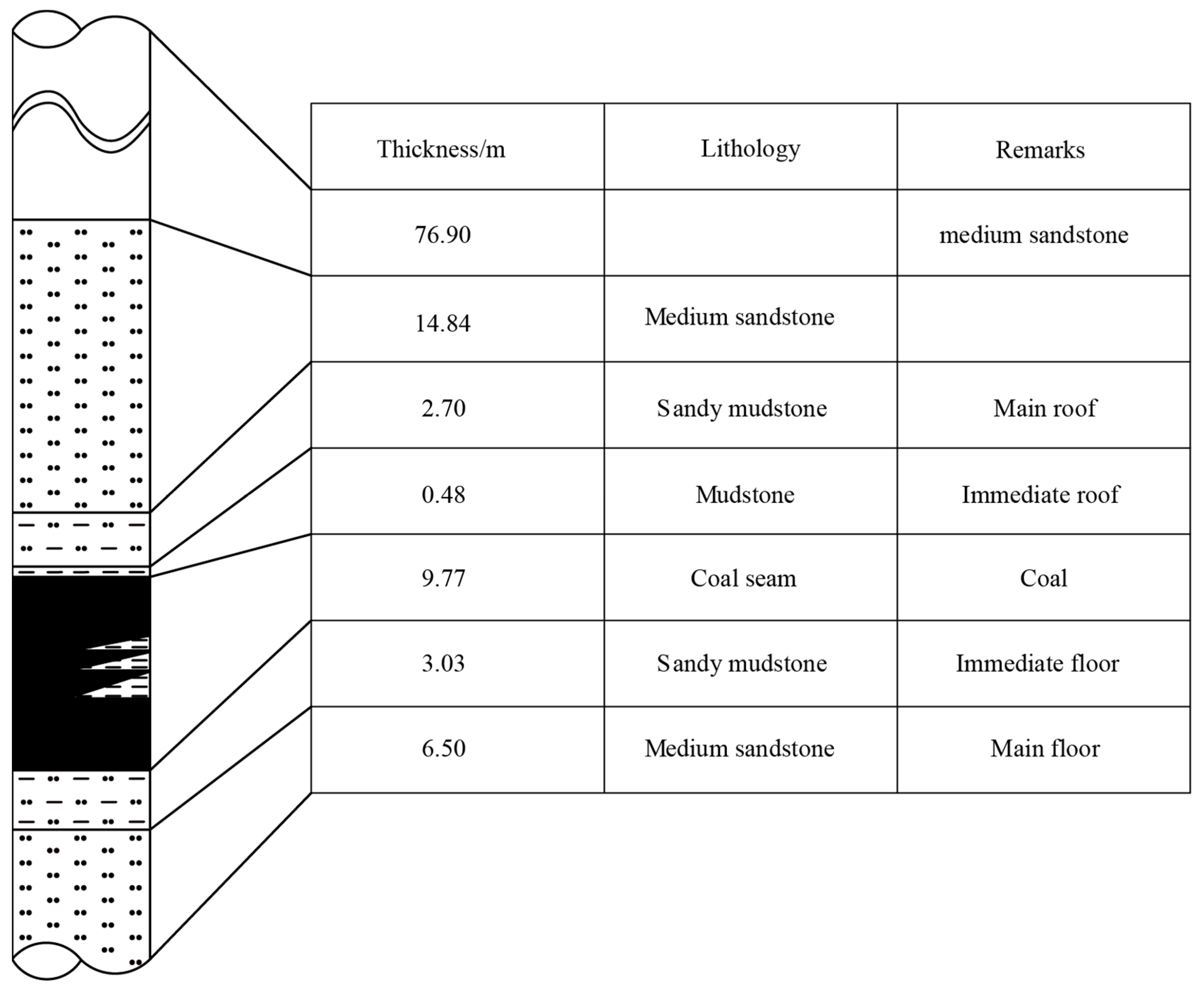
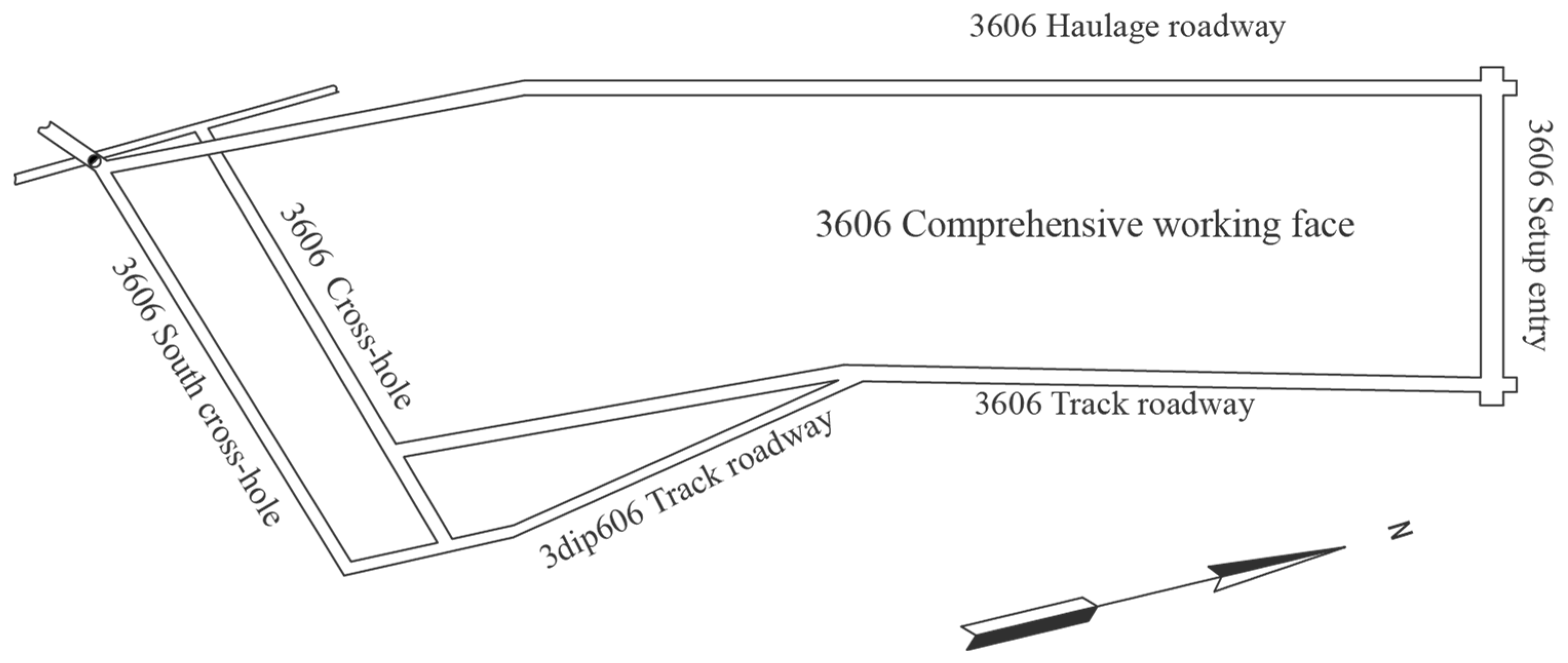
2. Site Geological and Engineering Characteristics

The Chaili Coal Mine is located in the northern part of the Tengnan coal field in Zaozhuang, which is relatively gentle, and the minefield fold structure is developed. The No. 3606 panel is located to the north of the first level six mining zone and has an average burial depth of 100 m. The dip angle of the coal seam is 1~6°, and the average dip angle is 4°. The thickness of the three coal seams is 6.84~13.70 m, with an average thickness of 9.77 m, and the thickness of local mudstone gangue containing one to three layers is 0~0.80 m.
The mining roadway of the No. 3606 panel is pushed along the roof of coal three. The roadway section is 4.6 m wide and 3 m high. Figure 1 shows the distribution of rock strata in the No. 3606 panel.
The 3606 track roadway is located to the north of the first level six mining zone. To the north lies the 3605-10 fault, while to the south is the goaf of the 3604 panel. The eastern and western sides are unmined areas. The 3606 haulage roadway is located to the north of the first level six mining zone, with the goaf of the 3603 panel to the south, the goaf of the 3605 panel to the west, the designed panel to the east, and the unmined area to the north. The layout of the 3606 panel roadway is shown in Figure 2.
The immediate roof of the 3606 trackway has a soft rock mass thickness of up to 4.91 m, with an average of 3.2 m. This roadway belongs to the thick layer of soft rock mass immediate roof roadway. The soft rock mass in the roof of such roadways is susceptible to deformation, and the deformation range can be significant. Insufficient prestressed anchoring range of the roadway support can lead to significant deformation, layer separation, or even roof fall. Therefore, it is important to determine a reasonable roadway support method and supporting parameters that are appropriate for the roof condition of a thick soft rock mass. This will help to ensure that the roadway is adequately supported and safe for use.

3. Full Anchor Cable Support Mechanism for the Immediate Roof of a Thick Soft Rock Mass Roadway

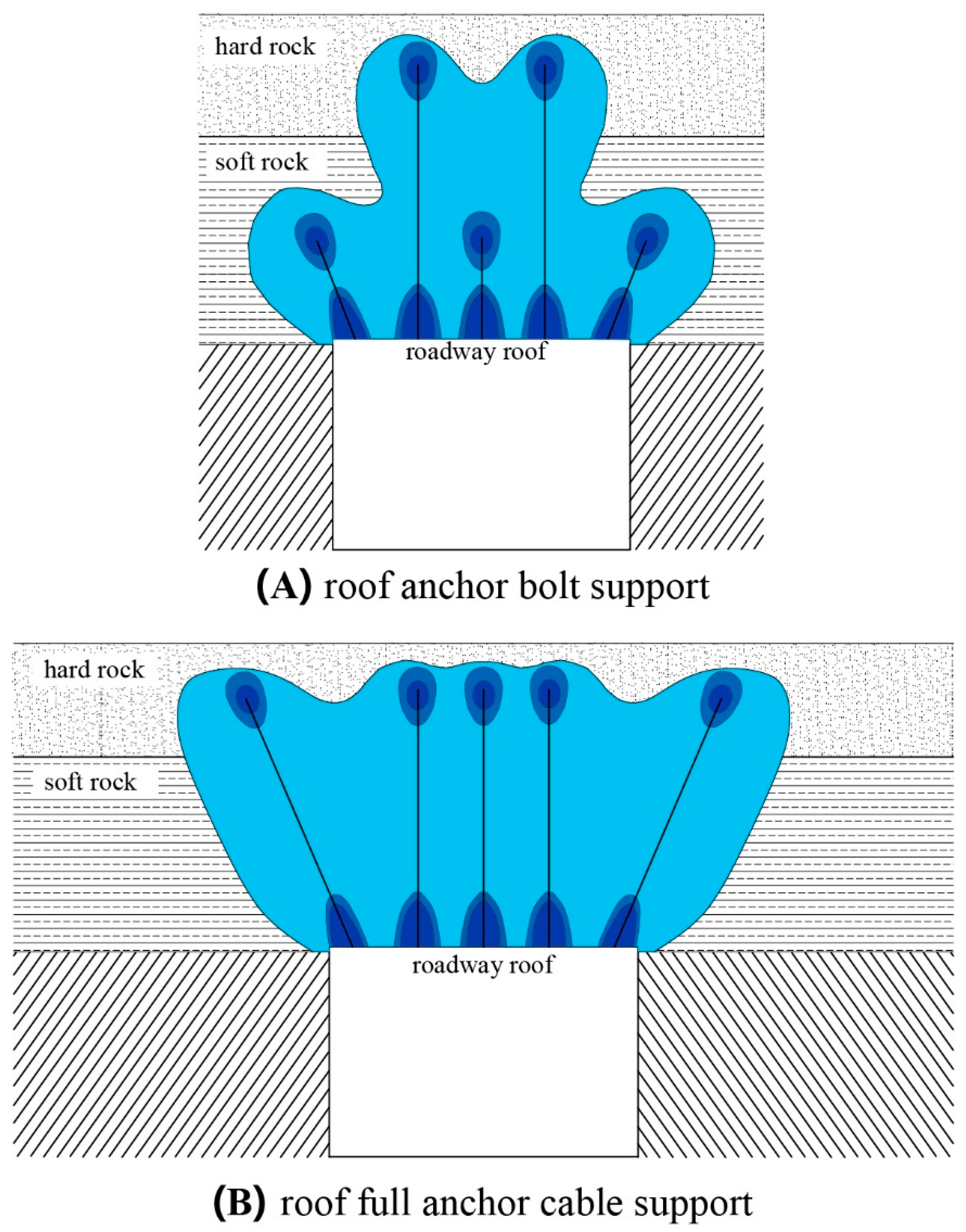
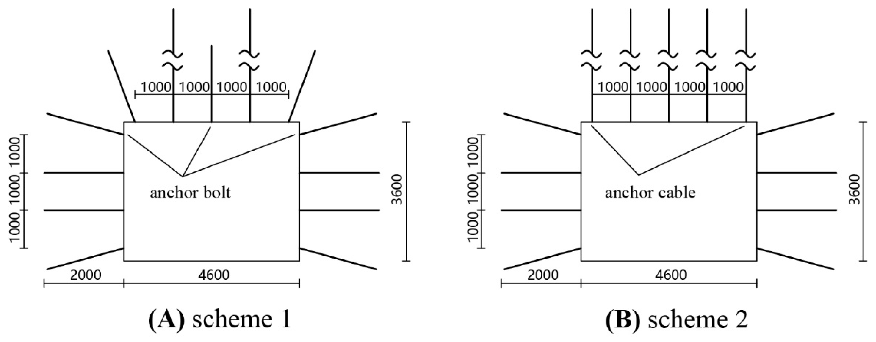
3.1. Support Mechanism Analysis

The immediate roof of trackway 3606 has a maximum soft rock thickness of 4.91 m, which is larger than the length of an ordinary anchor bolt. This means that the bolt cannot be effectively fixed in the solid rock stratum, making it difficult to support the roof effectively. From Figure 3A, it becomes clear that the roof cannot be effectively supported with a bolt-based support scheme because of the insufficient prestressed anchorage range.
The roof of the 3606 trackway is soft and thick, and its support body needs a large anchoring range. Only in this way can the soft rock be made more resistant to damage and keep the roof intact. Upon observing Figure 3B, the full anchor cable support scheme plays several important roles in supporting the roof of the 3606 trackway with its soft and thick rock mass. First, it provides support for the shallow surrounding rock, reducing the risk of dislocation and deformation failures. The strong prestress and large anchoring range of the anchor cables increase the compressive stress of the surrounding rock, which reduces the influence of tensile stress and prevents deformation and damage to the surrounding rock.
Second, the full anchor cable support scheme securely suspends the shallow loose surrounding rock from the roof, preventing it from collapsing and potentially damaging the roadway. The anchor cables are inserted deep into the stable rock strata, ensuring that the surrounding rock is held in place and the roof remains stable.
Finally, the plastic expansion zone deep in the roof is supported by anchor cables, which helps to control the plastic failure range of the roof and avoid roof movement. This ultimately ensures the safety of the roadway and protects the integrity of the support system. Overall, the full anchor cable support scheme plays a critical role in providing effective support for the thick and soft rock mass roof of the 3606 trackway.

3.2. Supporting Effect Numerical Simulation Analysis

To verify the efficacy of the full anchor cable support method for thick soft rock mass roofs, this section conducts a comparison and analysis of the full anchor cable support scheme with the commonly utilized roof bolt-anchor cable joint support by means of numerical simulations. The full anchor cable support scheme uses anchor cables as the primary support structure, whereas the bolt anchor cable joint support scheme uses both anchor bolts and anchor cables for support. Based on the supporting effects of these schemes, we further analyze and evaluate the feasibility of the full anchor cable support scheme.

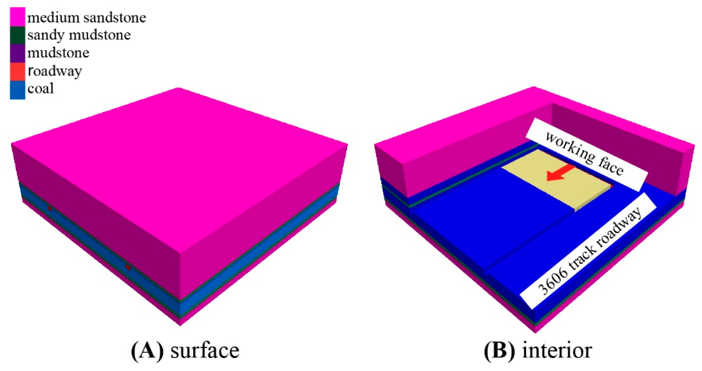
3.2.1. Numerical Simulation Calculation Model

  • (1) Model
The numerical model was established with the No. 3606 panel of Chaili Coal Mine as the background. The model’s overall length, width, and height were 200 m, 200 m, and 59 m, respectively. The model had a total of 546,480 blocks and 574,912 nodes. The simulation used brick elements to construct the model. The model, from top to bottom, included medium sandstone (36.8 m), sandy mudstone (2.7 m), mudstone (0.5 m), coal seam (9.5 m), sandy mudstone (3.0 m), and medium sandstone (6.5 m). The dip angle of each rock layer was 0°. The working face was parallel to the x-axis direction and advanced along the y-axis direction. Fabio used TENSO software (https://www.tensosoftware.com/, accessed on 10 April 2023), which includes modules for simulating finite element cable and beam models [25,26].The structural element of cables was used to construct the bolt and cable system. The structural element of cables in FLAC3D was used to construct the bolt and cable system in this paper. The numerical calculation model is shown in Figure 4.
This numerical simulation was computed using the Mohr–Coulomb constitutive model. The mechanical parameters of the simulated coal-rock layer were determined based on the geological report of the No. 3606 panel and coal-rock mechanics tests. The mechanical parameters of coal and rock are shown in Table 1. The boundary conditions of the model were as follows: the upper part of the model in the z direction was a free surface, and a vertical load was applied to simulate the self-weight load of the overlying strata. The bottom of the model in the z direction was limited in vertical displacement, while the horizontal displacement in both sides of the model was constrained. In order to eliminate the boundary effect, the distance between the roadway and the boundary was set to 50 m. The model was buried 60 m deep, and the average bulk density of the overlying rock was 26 KN/m3. Therefore, an equivalent load of 1.56 MPa needed to be applied to the top of the model, and a lateral pressure coefficient of 0.5 was taken, i.e., a horizontal stress of 0.78 MPa was applied in the x and y directions of the model.
To ensure that the most realistic results were obtained, the numerical simulation was carried out in the sequence of working face preparation and recovery. First, the stress state of the original rock was simulated, and the displacement was reset to zero after the simulation. Then, the excavation of the roadway was simulated, and the bolts or anchor cables were installed after the roadway was excavated. The solution was then performed. Finally, the excavation of the working face was simulated. The working face was excavated starting from the cutting hole, 10 m at a time, and the solution was performed after each excavation. The simulation ended after a total excavation of 80 m along the working face. After the simulation, the surrounding rock stress, displacement, and plastic zone of the two simulations were studied, and the support effects of the two schemes were compared.
Table 1. Mechanical parameters of coal and rock.
TypeDensity
(kg·m−3)
Elastic Modulus
(GPa)
Poisson’s RatioInternal
Friction
Angle (°)
Cohesion
(MPa)
Tensile
Strength
(MPa)
medium sandstone26312.760.2044.110.674.52
sandy mudstone2331.050.2838.72.831.13
mudstone21160.700.2729.32.310.47
coal13820.890.3132.43.010.64
  • (2) Simulation program
To verify whether the roof full anchor cable support method has a better support effect, it was compared with the roof bolt-anchor cable support method. In order to ensure that the support parameters of the roadway are realistic, the support parameters of the roof and two ribs were designed by referencing the mining roadway support scheme adjacent to the 3606 track roadway. To ensure a fair comparison, the specifications of the anchor rods and anchor cables were kept the same for both schemes, and the spacing, row spacing, and preload applied by the anchor cables were also kept the same.
To meet the aforementioned requirements, the combined roof bolt-anchor cable support scheme (Figure 5A) and the roof full anchor cable support scheme (Figure 5B) were designed. Figure 5 shows the roadway section, and the unit is mm. In the two schemes, the anchor bolt was threaded steel with specifications of L2000 mm and Φ20.0 mm, the anchor cable was a steel strand with specifications of L5500 mm and Φ17.8 mm, the supporting row spacing was 1.1 mm, and the anchor cable preload was 100 kN. In the simulation, the anchor bolt was selected with an elastic modulus parameter of 100 GPa and a tensile strength parameter of 490 MN. As for the cable anchor, an elastic modulus parameter of 200 GPa and a tensile strength parameter of 1860 MN were chosen.

3.2.2. Analysis of Failure Effect

This simulation only studied the support effect of the thick soft rock mass roof in the mining roadways, so the extent of deformation and damage to the roadway roof was mainly analyzed.
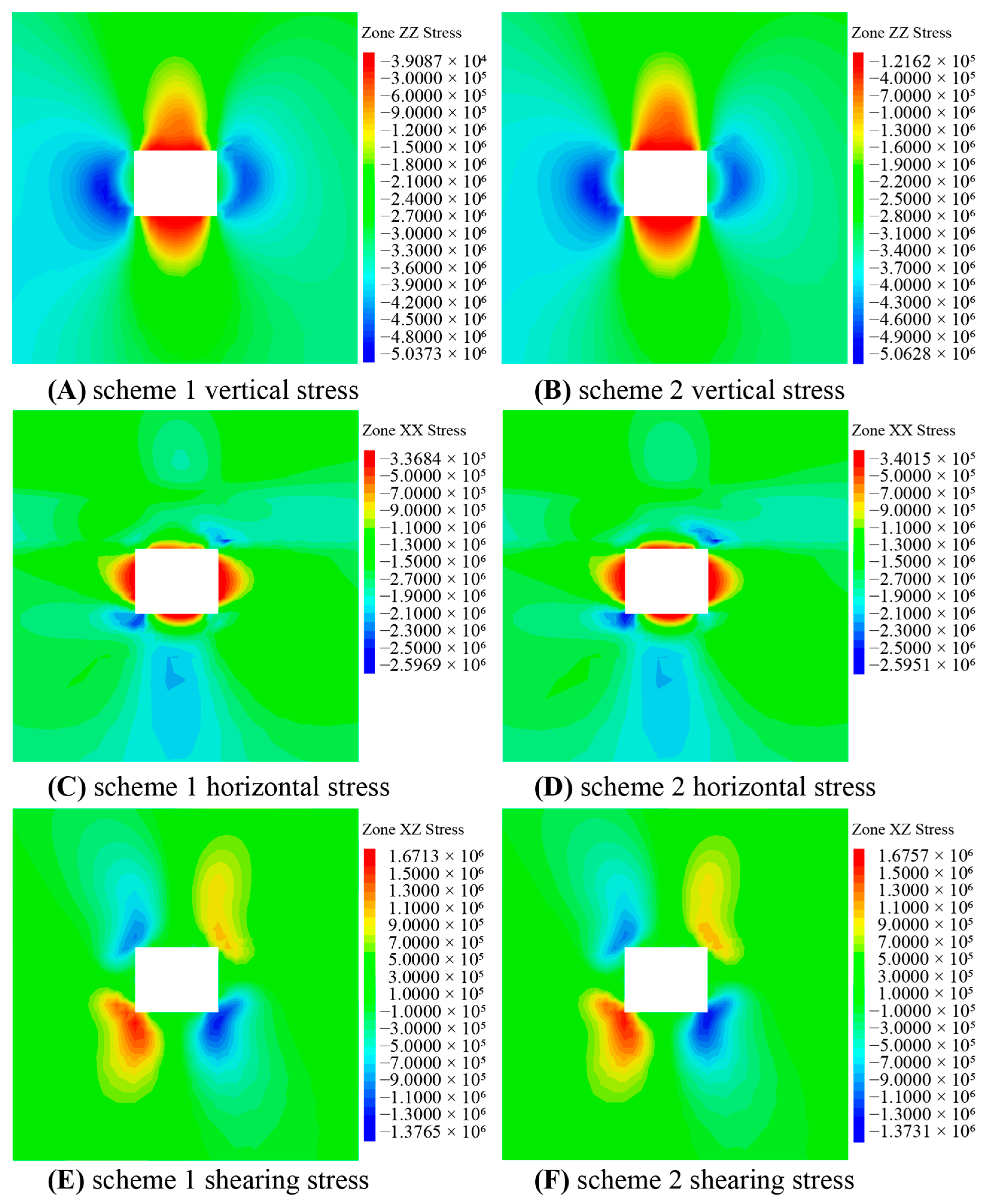
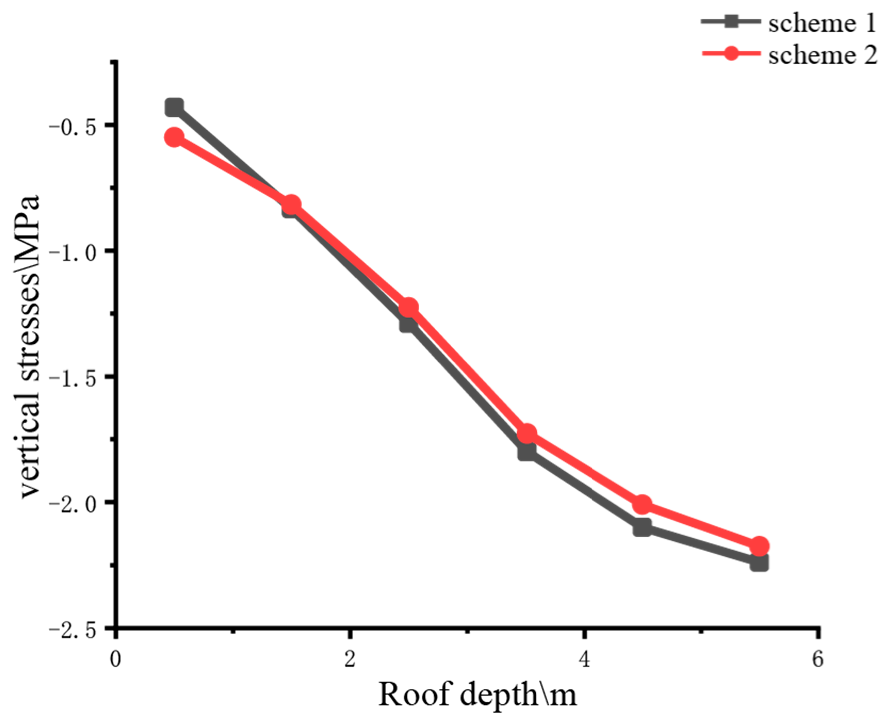
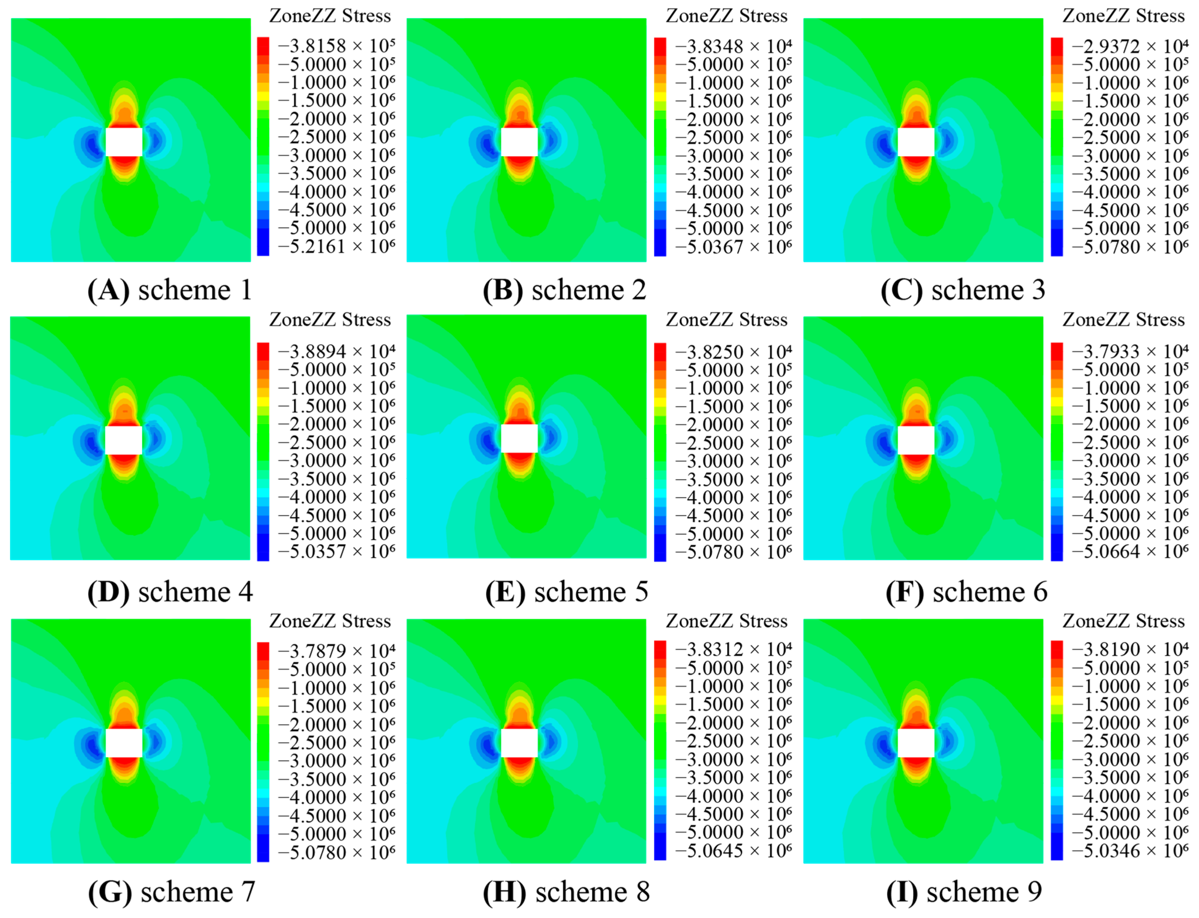
  • (1) Analysis of stress variation law
The stress cloud maps of the roadway around the rock 15 m in front of the working face for both schemes are shown in Figure 6.
According to the figure, the roadway surrounding rock horizontal and shear stresses are roughly the same in both schemes, and only the vertical stress of the roadway roof needs to be focused on for both schemes.
The stress concentration phenomenon on the roadway roof is a critical factor that affects the stability of the roadway. When stress concentration occurs, the roadway surface is more susceptible to damage, which can lead to safety hazards. As shown in Figure 7, it can be concluded that the full anchor cable support scheme of the second scheme is better at stabilizing the roadway roof compared to the first scheme. The lower vertical stress on the roof in the second scheme indicates that the full anchor cable support method can effectively reduce the stress concentration phenomenon and prevent damage to the roadway surface.
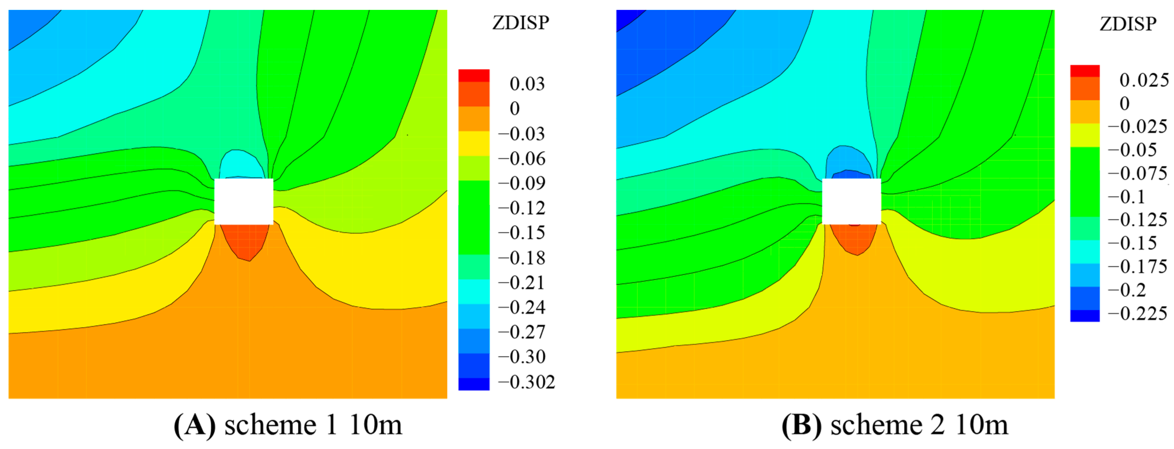
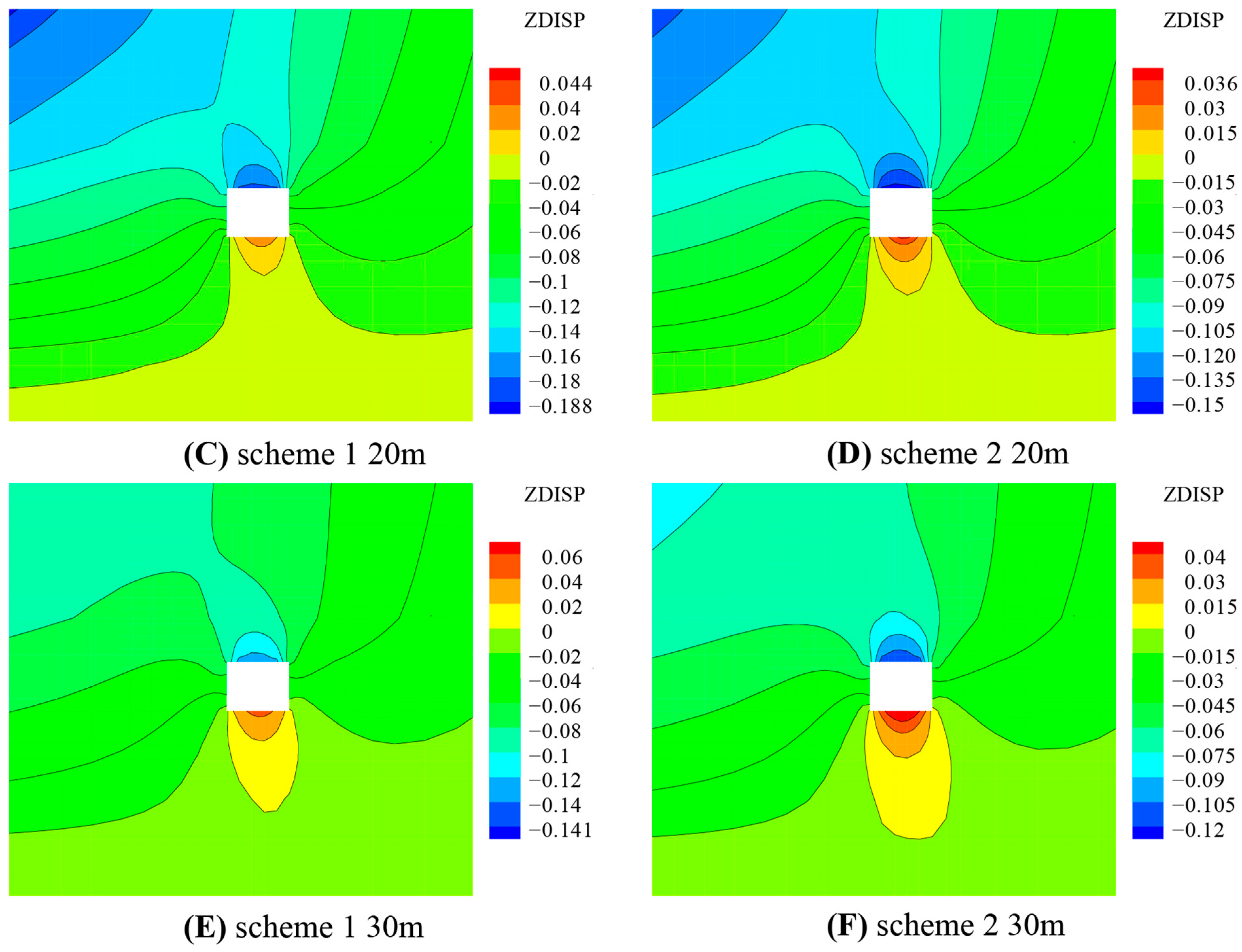
  • (2) Analysis of deformation law and plastic development status of roof
The coal rock mass is in the stress state of the original rock before being affected by the excavation of the roadway. Once the excavation is made, the stress state of the surrounding rock changes, and the stress redistribution leads to the deformation and damage of the rock. In general, the stress or stress concentration factor of the surrounding rock indirectly indicates the support effect of the roadway, while the deformation and plastic failure of the surrounding rock more intuitively demonstrate the roadway support effect. To better compare the two schemes, the deformation and plastic distribution of the roadway surrounding rock at different positions were observed and analyzed.
From Figure 8, we can observe the deformation law of the surrounding rock. The unit in the figure is in m. The displacement of the roof was the largest, and the bottom plate was the smallest, indicating that the roadway support mainly controls the deformation of the roof. When analyzing a single scheme, it was found that the larger the distance between the roadway and the working face, the smaller the displacement of the roof and the smaller the displacement of the surrounding rock of the roadway. This is because the influence of the advanced pressure decreases with the distance from the working face, resulting in a smaller deformation of the surrounding rock.
Comparing the two schemes, it can be seen that the displacement of the roof in Figure 8A,C,E is much larger than that in Figure 5B,D,F at the same position, indicating that scheme 2 has a better control effect on the deformation of the roadway.
According to the plastic zone distribution cloud diagram in Figure 9, it is found that the largest plastic failure area is at the two corners of the roadway roof, and the plastic zone in the middle of the roof is relatively small. At a distance of 10 m in front of the working face, the roof of Figure 9A was severely damaged, while the plastic failure area at the two corners of the roof in Figure 9B was relatively large and the plastic failure area in the middle of the roof was relatively small. At 20 m, the plastic failure area at the two corners of the roof was relatively large in Figure 9C, the plastic failure area in the middle of the roof was moderate, and the overall plastic zone of the roof in Figure 9D was relatively small. At 30 m, the plastic failure areas of both schemes were relatively small. Therefore, under the influence of the advanced bearing pressure, the support effect of scheme 2 in Figure 5B is better.
Table 2 presents the simulation results. Based on the comprehensive analysis of the surrounding rock displacement and plastic damage, the full anchor cable support scheme for the roadway roof was found to have a better support effect than the bolt-anchor cable joint support scheme. The displacement of the surrounding rock was smaller, and the plastic damage zone of the roadway roof was also smaller. The roadway damage range and degree were also smaller under the full anchor cable support scheme. Moreover, the full anchor cable support scheme can provide stable support for the roadway roof in the range of 25 m in front of the working face, which is difficult to achieve by the bolt-anchor cable joint support scheme. Therefore, for roadways with thick soft rock and thick layers, the full anchor cable support scheme is a safer and more reliable choice.
Based on the stress, deformation, and plastic zone distribution of the surrounding rock in the two numerical simulation schemes, it can be concluded that the full anchor cable support scheme had a better support effect on thick soft rock compared to the roof bolt-anchor cable joint support scheme. Additionally, there was no risk of roof instability with the full anchor cable support scheme, indicating that the roof anchored with bolts and cables had a poor support effect. Therefore, the feasibility of the fully anchored roof support scheme is higher.

4. Determination of Full Anchor Cable Support Parameters

4.1. Roadway Support Scheme Design

Based on field support experience and suspension theory [27], a set of support parameters within a reasonable range were selected and combined to determine the best plan.
The length of the anchor cable is determined by the following equation:
L = L 1 + L 2 + L 3
In the equation, L1 represents the length of the prestressed anchor cable in the anchored section in meters (m), L2 represents the length of the prestressed anchor cable in the free section in meters (m), and L3 represents the exposed tension length, which is typically taken as 0.2 m.
The required spacing of the roof anchor supports to withstand the weight of the pressure arch can be determined by the following equation:
a = R T K γ h
In the above equation, a represents the spacing of the roof anchor bolts measured in meters. RT represents the anchoring force of the anchor bolts measured in kilonewtons (kN). K represents the safety factor of the prestressed anchor bolts. γ represents the average unit weight of the overlying rock strata, expressed in kg/m3. h represents the effective length, which refers to the actual working length or the effective supporting length of the prestressed anchor cable. It is typically measured in meters (m).
These parameters are shown in Table 3. A 17.8 mm diameter steel strand was used as the anchor cable, and corresponding anchoring agents were used. The preload for each support scheme was set at 150 kN.
The support parameters of the adjacent working faces were used as a reference to determine the parameters of the two schemes, with only the row spacing of the anchor bolts adjusted accordingly. In both schemes, four bolts were arranged on two ribs of the roadway, with a distance of 1000 mm between bolts and an angle of 70° between the surrounding rock and the upper and lower bolts.

4.2. Simulation Result Analysis

4.2.1. Surrounding Rock Stress Analysis

As shown in Figure 10, the vertical stress on the roadway roof is the smallest, followed by the stress on the roadway floor, while the vertical stress on the two ribs of the roadway is the largest, and the surrounding rock is under compressive stress. From the stress distribution contour map, it can be seen that the minimum stress on the roof and floor of the roadway is at the surface of the roadway, and the maximum stress on the two ribs is in the deep part of the coal wall. The more significant the stress concentration in the roadway, the poorer the support effect of the surrounding rock. Therefore, to study the support effect of different support schemes in the roadway, we will focus on comparing the vertical stress on the surface of the roof and the deep part of the two ribs.
Simulations show that the vertical stresses downward on the roof from Figure 10A–I are 0.192 MPa, 0.169 MPa, 0.126 MPa, 0.197 MPa, 0.138 MPa, 0.196 MPa, 0.150 MPa, 0.197 MPa, and 0.162 MPa, respectively. If the vertical stress on the roadway roof surface is larger, the vertical direction of the stress variation is smaller, and the stress concentration is smaller. Among them, the vertical stresses of Figure 10A,D,F,H were larger than those of the other schemes. This shows that the stress state of roof surrounding rock was better under these schemes. The surrounding rock was less at risk of failure and the roof was more stable.

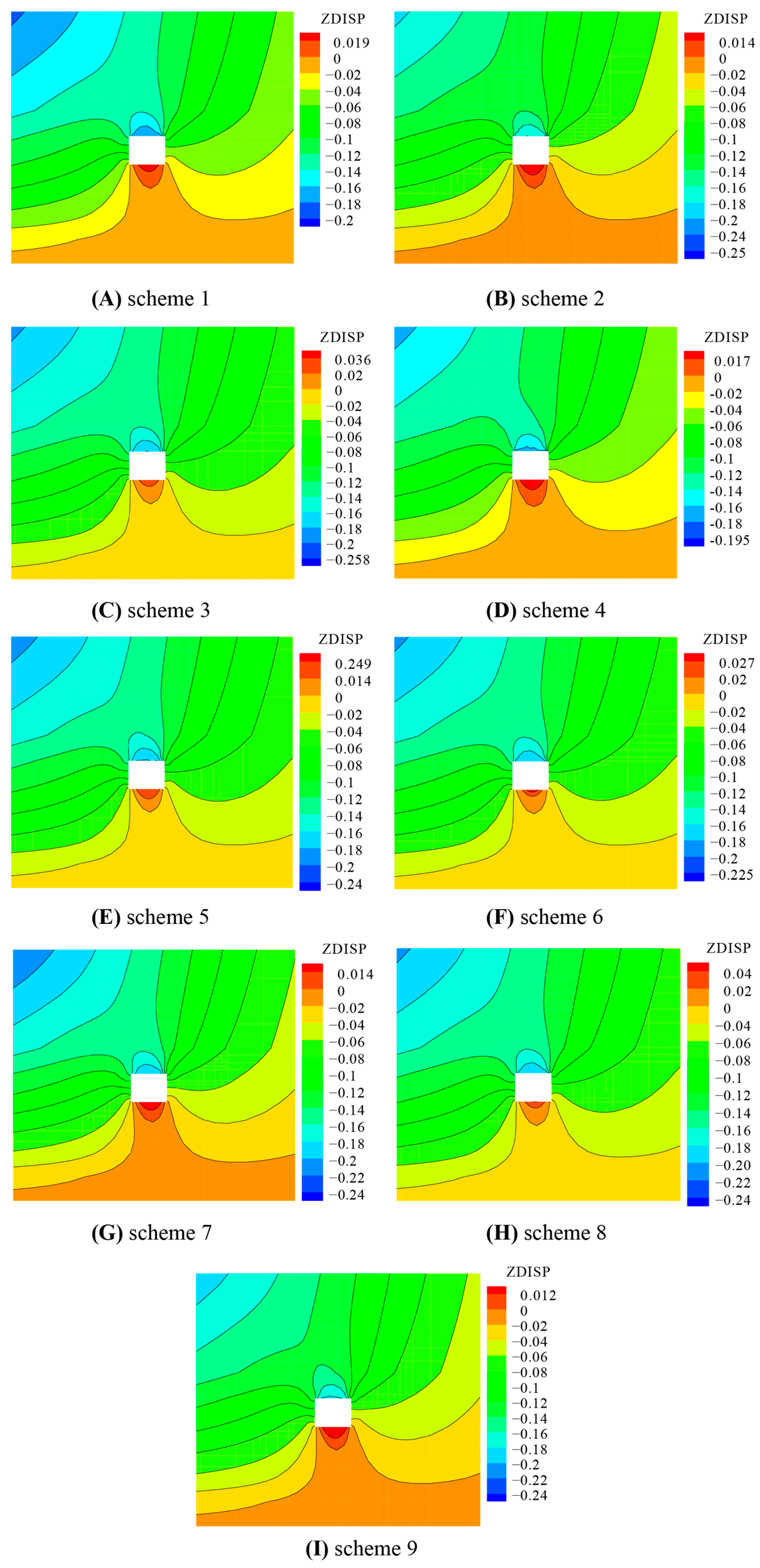
4.2.2. Surrounding Rock Displacement Analysis

As seen in Figure 11, the vertical displacement of the roadway floor is small. The unit in the figure is in m. However, the vertical displacement of the roadway roof is substantial. The largest roadway displacement is on the roof surface. By comparing the maximum displacement of the roadway roof surface, we can derive the control effects of different support schemes on the roof displacement of the roadway.
From Figure 11A–I, the displacement of the roadway roof was 189.4, 189.8, 194.6, 182.5, 190.6, 187.4, 187.4, 185, and 181.8 mm, respectively. Figure 11A–C,E had relatively large rock displacements, while the other schemes had relatively small displacements and better control of the roadway roof.

4.2.3. Surrounding Rock Plastic Zone Analysis

The plastic zone of the surrounding rock of the roadway 15 m in front of the working face is shown in Figure 12.
It is difficult to compare the size of the plastic zone from the range of the plastic zone of the top plate and the two sides in these schemes. In order to analyze the plastic failure situation specifically, the plastic failure area of the top plate and the two sides was compared here. According to the calculation of the average area per grid of 0.212 m2, the variation curve of the surrounding rock plastic zone of the roadway is shown in Figure 13.
The plastic zone of the surrounding rock in the roadway indicates plastic failure of the rock mass. The low strength of the surrounding rock in plastic failure will reduce the overall bearing capacity of the roadway. According to Figure 12 and Figure 13, it can be seen that the overall plastic failure area of Figure 11A–C is larger than that of the other schemes. Therefore, Figure 11A–C have weaker abilities to suppress plastic failure of the surrounding rock, while Figure 11D–I have relatively good supporting effects. Among them, Figure 11D,F have the best supporting effects.

4.3. Determine the Support Scheme

In summary, among the analyzed schemes, when implementing support schemes 4, 6, and 8 from Table 2, the roadway exhibits better surrounding rock stress states, smaller surrounding rock displacements, and a smaller range of plastic failure. When considering the economic aspect, scheme 6 in Table 2 requires fewer bolts and anchor cables compared to scheme 4 due to the larger row spacing. Furthermore, when compared to scheme 8 in Table 2, scheme 6 has a larger row spacing and shorter length, resulting in a reduced requirement for bolts and anchor cables. Therefore, scheme 6 in Table 2 can be considered the plan with the most comprehensive support function, the best effect, and the scheme that conforms to the principle of economy and practicability among the analyzed schemes. To ensure the anchoring quality of the anchor cable, the diameter of the anchor hole, anchor cable, and resin cartridge should be properly matched when using the MSK2550 resin cartridge anchoring agent for anchor cable installation. Therefore, the design diameter of the anchor hole was set to 28 mm.

5. Field Application and Effect Evaluation

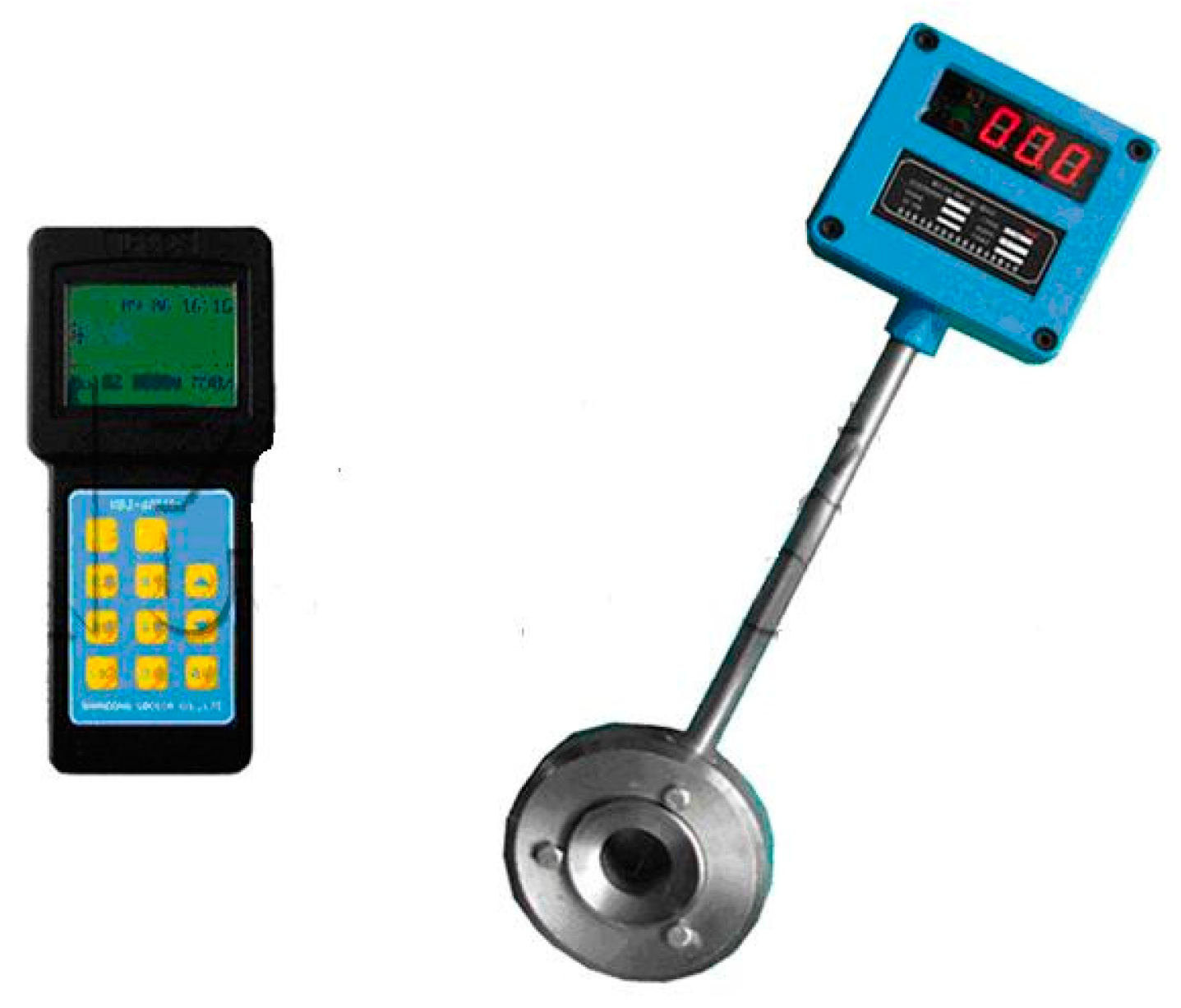
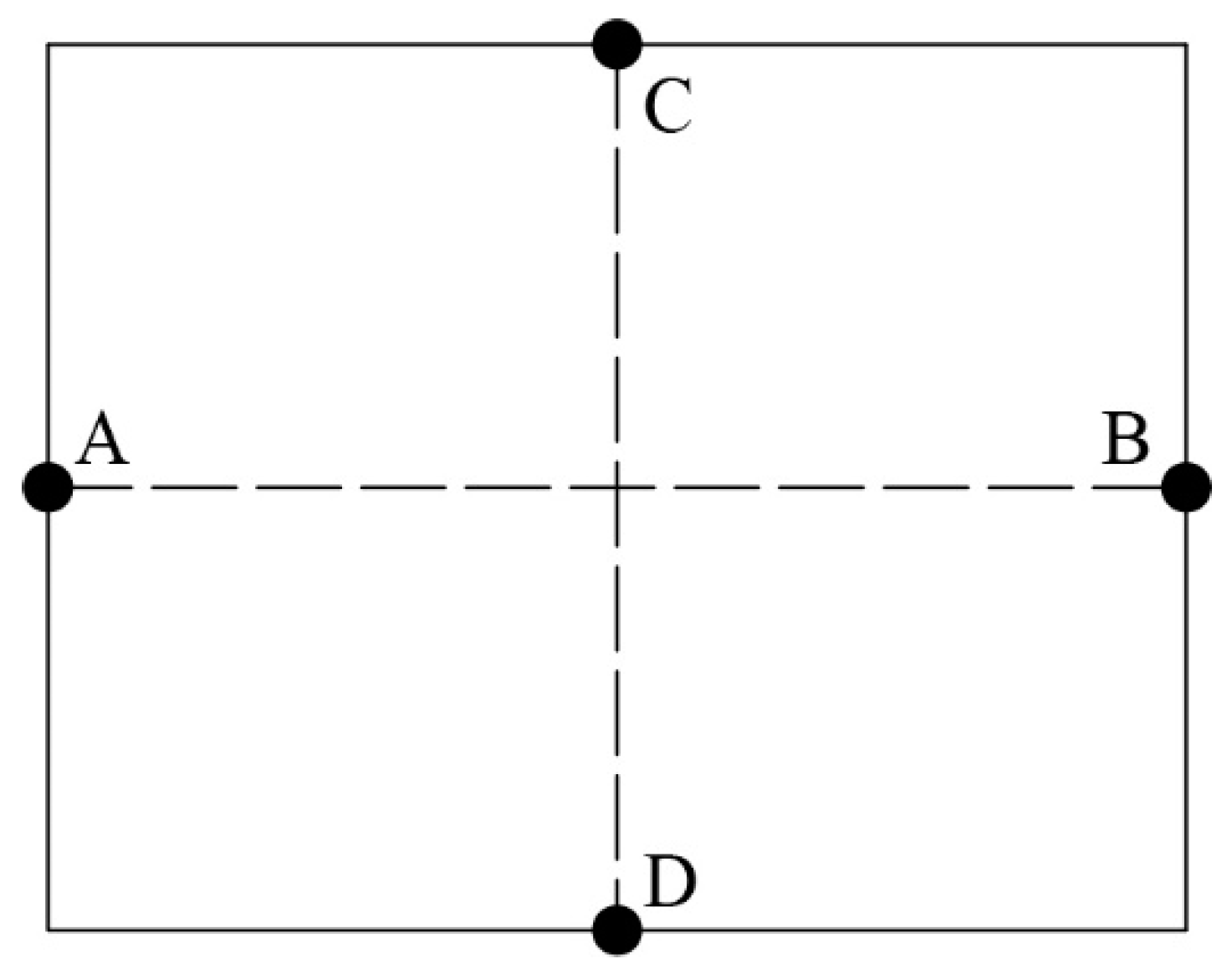
5.1. Monitoring Program

The purpose of this study is to analyze the effectiveness of the roof full anchor cable support method and the support parameters used in the trackway of the No. 3606 panel. To achieve this, two measurement stations were set up in a representative area of the trackway, one at 220 m and the other at 250 m from the working face. These stations were designed to monitor the roof-to-floor convergence and record the working resistance of the anchor bolts and cables used in the support method.
The measurement points for the working resistance of the anchor cable were arranged in two measurement stations, labeled as station A and station B, located at 220 m and 250 m, respectively, from the working face in a representative area of the trackway. At station A, two dynamometers, labeled as 1# and 2#, were installed on the anchor cable on the roof, while two dynamometers were installed on the anchors of two ribs: the production rib, labeled as 3#, and the non-production rib, labeled as 4#. Similarly, station B had the same arrangement with dynamometers numbered from 5# to 8#. The bolt and cable dynamometer is shown in Figure 14, with the sensing device on the right and the data collector on the left. During the installation of the anchor cable and dynamometer, the installation torque should be no less than 150 N·m.
The bolt and cable dynamometer comprised a sensing device and a data collector. During installation, the load dynamometer was placed between the anchor bolt/cable saddle and nut, and the nut was tightened using a torque wrench to apply the specified pre-tensioning force. The data collector was then handheld and aimed directly at the sensor display screen to read the data. The load dynamometer was read once per day for the first 5 days after installation, and then every 3–5 days thereafter. When the monitoring point was within 100 m of the working face, it was observed once a day. Layout plan of anchor bolt and cable dynamometer as shown in Figure 15.
The rock displacement monitoring scheme depicted in Figure 16 involves four measurement points at each station arranged around the roadway layout. These points are used to monitor the distance between A and B and between C and D. To set up each measuring point, a 0.5 m deep, 29 mm diameter borehole should be drilled into the coal and rock mass. Then, a 0.53 m long, 22 mm diameter threaded steel bar should be inserted into the center of the borehole and anchored in place with an anchoring agent. The steel bar should protrude by 30 mm, while the steel bar at the floor measuring point does not need to be exposed.
The displacement monitoring method used involves the use of a handheld laser rangefinder to measure the distance between points A and B and between points C and D. From the initial measurement, subsequent movements of the roof, floor, and two ribs were calculated. The first measurement was taken one day after the layout of the measurement points was completed, and data were collected once a day for the first five days. Afterward, measurements were taken once every three to five days. When the measurement point was within 100 m from the working face, observations were conducted once a day, and when the measurement point was within 50 m from the working face, observations were conducted twice a day.

5.2. Analysis of Mine Pressure Appearance

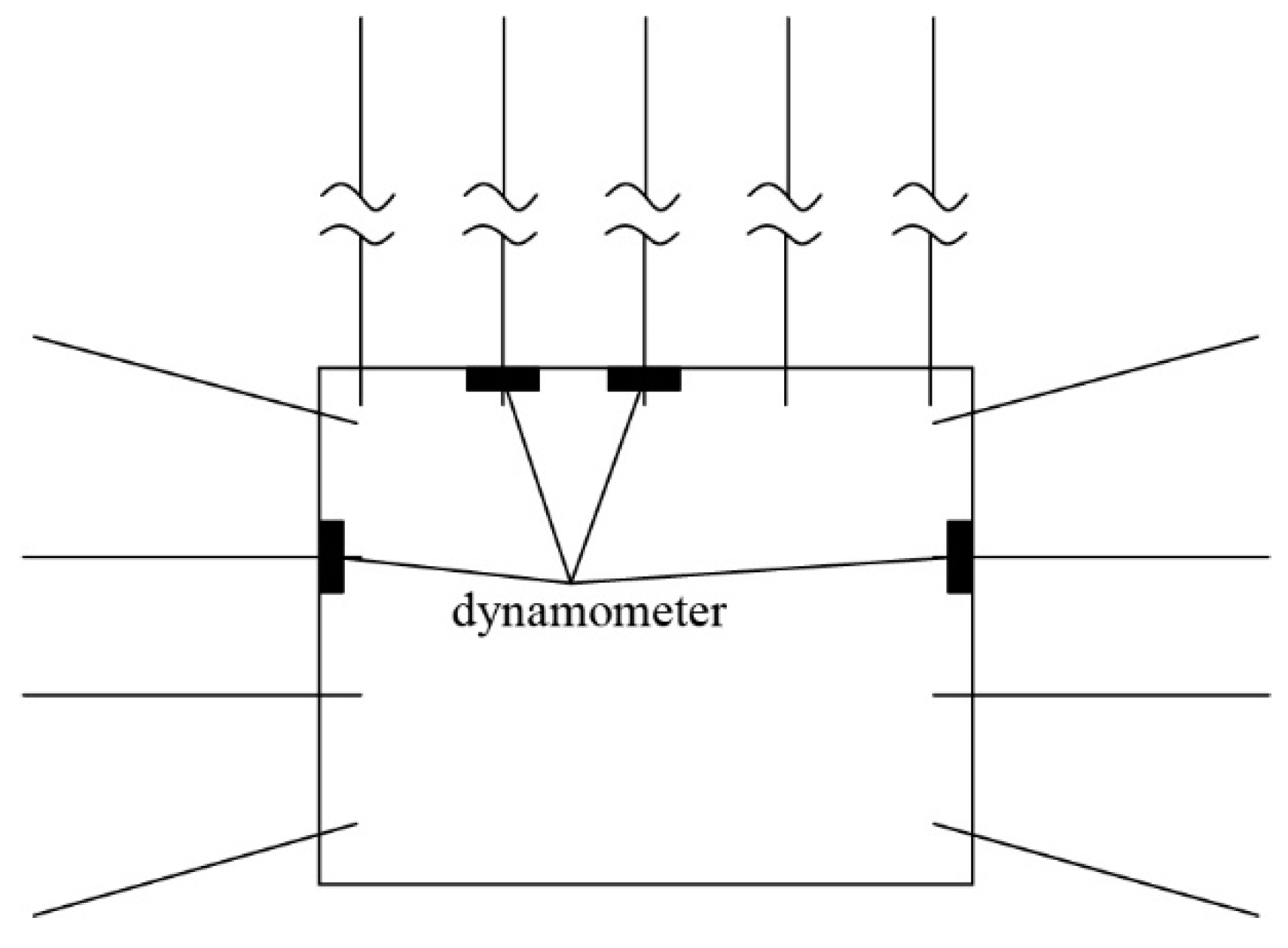
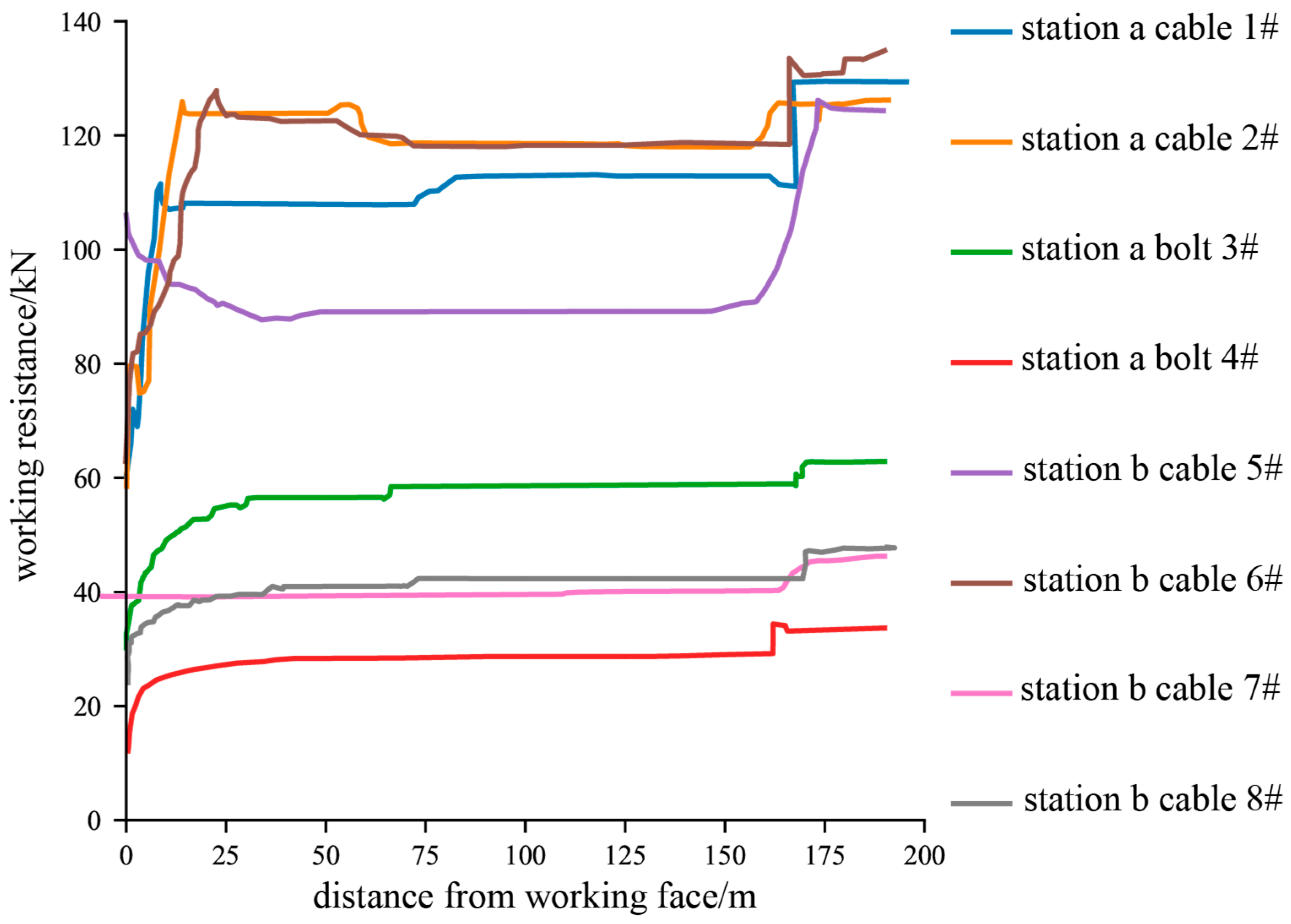
5.2.1. Force Analysis of Anchor

The monitoring of the working resistance began when the working face was 200 m away from the measurement point. The monitoring was terminated when the working face approached the measurement point. Figure 17 displays the variation curves of the working resistance of the bolt-anchor cable at measurement points 1# to 8#.
As the working face approaches the measuring point to about 30 m, the supporting resistance of the bolt and cable increases significantly, and the working resistance increases to a certain value, after which it reaches the maximum. The roof rock is well supported during mining, and the surrounding rock’s two ribs are anchored, ensuring the stability of the roadway.

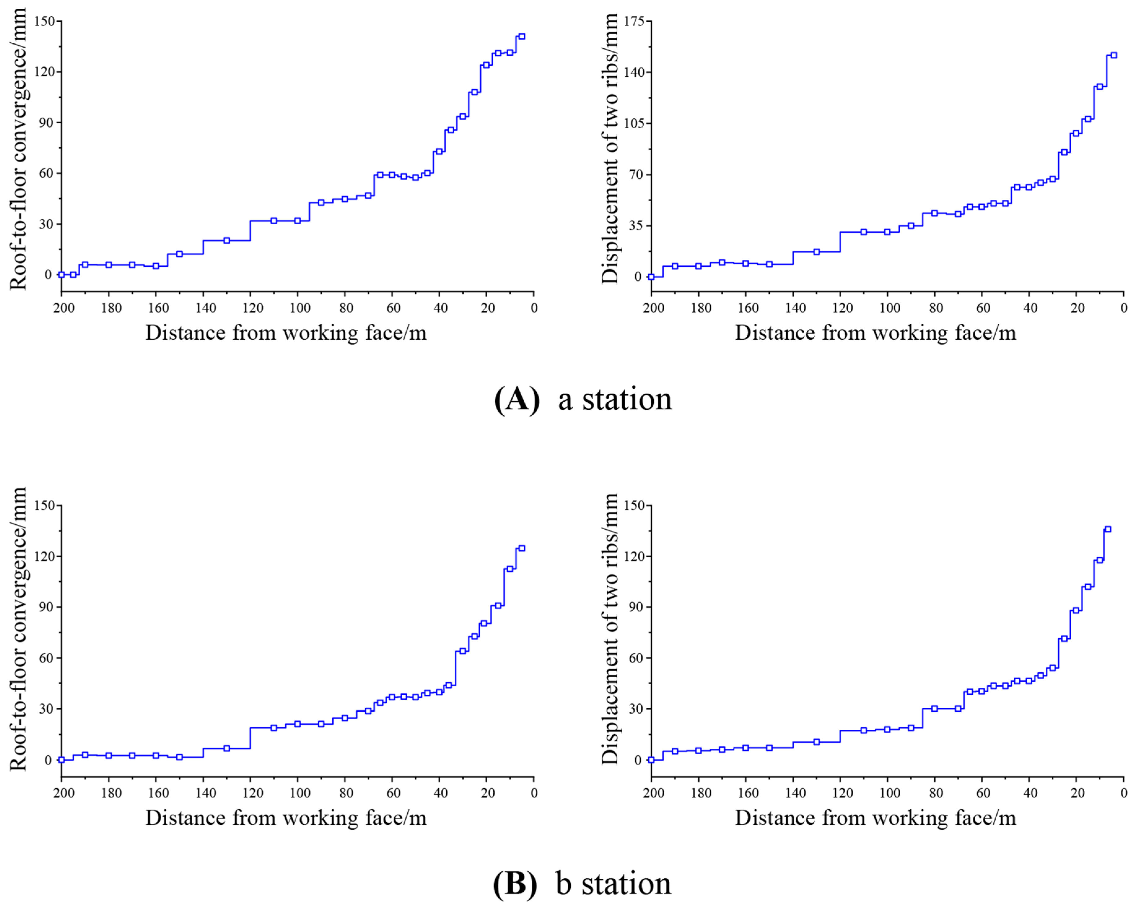
5.2.2. Surrounding Rock Deformation Analysis

Starting 200 m ahead of the working face, two measuring stations began to monitor the amount of roadway displacement. Station a and station b respectively. Summarizing the data recorded at each time, a curve was plotted for the displacement of the roadway as a function of the distance from the working face, as shown in Figure 18.
The advanced bearing pressure cannot be detected when the measurement point is far from the working face. When the working face moves forward, these measuring points are gradually affected by the advanced bearing pressure, and then the surrounding rock deformations gradually increase. The 3606 track roadway’s surrounding rock deformation and relative deformation rate are both minor, according to the surrounding rock displacement observation. This scheme successfully controlled the deformation of the roof and two ribs.

5.3. Support Effect Analysis

In the field monitoring using the roof full anchor cable support scheme, the average maximum working resistance of the anchor bolts and anchor cables was 53 KN and 124.5 KN, respectively. The anchor bolts and cables worked properly, giving full play to their active support functions; the convergence of roof-to-floor and two ribs displacement was 132.5 mm and 144 mm, respectively, with relatively little surrounding rock displacement. The heave of the roadway floor was minimal, and no significant uplift or cracking phenomena were observed during the monitoring. This condition did not have any adverse effects on the subsequent use of the roadway. This situation showed that the roof’s full anchor cable support scheme provided good support on the 3606 track roadway, and that the surrounding rocks’ plastic failure and distortion were contained. This demonstrates the safety and reliability of the full anchor cable scheme for the thick soft rock mass roof of the mining roadway.

6. Conclusions

This study was based on the engineering basis of the No. 3606 panel of the track roadway of the Chaili Coal Mine, which has a thick layer and soft rock mass roof. Using a combination of theoretical analysis, numerical simulations, and field applications, we systematically studied the full anchor cable support of a thick-layer soft rock mass roof in mining roadway technology, drawing the following main conclusions:
(1)
Comparing the roof full anchor cable support method to the roof bolt and anchor cable combined support method, theoretical analysis of the support function and effect was performed. The roof’s shallow surrounding rock was efficiently restrained from deforming and being damaged by the roof full anchor cable support method, maintaining the roof’s structural integrity. Therefore, full anchor cable support of thick soft rock roof was proposed;
(2)
Numerical simulation analysis and comparison of the support effect of roof full anchor cable support and roof bolt-anchor cable support in the mining process showed a relatively high risk of roof instability due to the deformation of the surrounding rock and plastic failure of the bolt-anchor cable support scheme. The roof full anchor cable support scheme can meet the support requirements;
(3)
By combining the support experience of the Chaili Coal Mine, the approximate support parameters for the roof and two ribs were determined. Then, nine support schemes were designed for numerical simulations using orthogonal experiments, and the support effectiveness and cost-effectiveness of each scheme were analyzed and compared. Based on the numerical simulation results, the final parameters for the roof’s full anchor cable support were determined as follows: the spacing between the roof anchor cable rows was 1200 × 1000 mm, and the spacing between the two ribs of anchor rod rows was 1200 × 1000 mm;
(4)
When the roof full anchor cable support scheme was applied in the 3606 track roadway, the average maximum working resistance of the anchor bolts and anchor cables was 53 KN and 124.5 KN, the convergence of roof-to-floor and two ribs displacement was 132.5 mm and 144 mm, and the deformation rate was 3.68% and 3.13%, respectively. The support resistance maintained a stable working status, and the roadway was well stabilized, proving that the thick soft rock mass roof of the mining roadway was well anchored. The adaptability of the full anchor cable support method for thick soft rock roadway roof support and the rationality of supporting parameters were demonstrated.
This paper only analyzed the thick soft rock roof conditions specific to the No. 3606 track roadway in the Chaili Coal Mine and studied the full anchor cable support technique. However, for thick soft rock roofs under different conditions, there are various types of soft rocks with different deformation and failure mechanisms and varying thicknesses. The adaptability and scope of using full anchor cable support for the roof require further systematic research.

Author Contributions

Conceptualization, writing—review and editing, and supervision: Y.Y.; data curation, formal analysis, methodology, and writing—review and editing: L.M.; software and validation: T.Z.; All authors have read and agreed to the published version of the manuscript.

Funding

This research was supported by the National Natural Science Foundation of China (grant nos. 51574156) and the Natural Science Foundation of Shandong Province of China (grant no. ZR2022ME195).

Institutional Review Board Statement

Not applicable.

Informed Consent Statement

Not applicable.

Data Availability Statement

Data associated with this research are available and can be obtained by contacting the corresponding author upon reasonable request.

Conflicts of Interest

The authors declare no conflict of interest.

References

  1. Yang, R.S.; Li, Y.L.; Wang, M.S.; Zhu, Y.; Cheng, Y.X.; Xiao, C.L.; Zhao, Y. Experimental study on shear mechanical properties of prestressed anchor cables. J. China Univ. Min. Technol. 2018, 47, 1166–1174. [Google Scholar] [CrossRef]
  2. Li, H. Study on the Lateral Performance and Excavation-Induced Response of Pile Foundations in Soft Soils; Southeast University: Nanjing, China, 2019. [Google Scholar]
  3. Liang, J. Study on softening critical depth of coal and rock mass in deep mining. China Energy Environ. Prot. 2020, 45, 78–184. [Google Scholar] [CrossRef]
  4. Li, T.C.; Lu, Z.; Liu, J.Z.; Ma, X. Deformation and failure process analysis of rectangular roadway in muddy weakly cemented soft rock strata. Rock Soil Mech. 2014, 35, 1077–1083. [Google Scholar] [CrossRef]
  5. Zhou, K.; Yu, F.; Tan, Y.; Zhao, T.; Guo, W. In-situ investigation on fractured evolution law of surrounding rock in weakly cemented soft rock roadway. Energy Sources Part A Recovery Util. Environ. Eff. 2021, 43, 1–13. [Google Scholar] [CrossRef]
  6. Meng, Q.; Han, L.; Qiao, W.; Lin, D.; Wen, S.; Zhang, J. Deformation failure characteristics and mechanism analysis of muddy weakly cemented soft rock roadway. J. Min. Saf. Eng. 2016, 33, 1014–1022. [Google Scholar] [CrossRef]
  7. Meng, Q.; Qian, W.; Han, L.; Wei, L.; Wang, C.; Zhou, X. Experimental study on formation mechanism and mechanical properties of regenerated structure of very weak cemented rock mass. Rock Soil Mech. 2020, 41, 799–812. [Google Scholar] [CrossRef]
  8. He, M.C.; Ma, X.G.; Niu, F.L.; Wang, J.; Liu, Y.X. Adaptability research and application of rapid gob-side entry retaining formed by roof cutting and pressure releasing with composite roof and medium thick coal seam. Chin. J. Rock Mech. Eng. 2018, 37, 2641–2654. [Google Scholar] [CrossRef]
  9. He, M.; Ma, Z.; Guo, Z.; Chen, S. Key parameters of the gob-side entry retaining formed by roof cutting and pressure release in deep medium thickness coal seams. J. China Univ. Min. Technol. 2018, 47, 468–477. [Google Scholar] [CrossRef]
  10. He, M.; Qi, G.; Cheng, P.; Zhang, G.; Sun, X. Deformation and damage mechanisms and coupling support design in deep coal roadway with compound roof. Chin. J. Rock Mech. Eng. 2007, 26, 987–993. [Google Scholar]
  11. He, M.C.; Wang, Y.; Yang, J.; Gao, Y.B.; Gao, Q.; Wang, S.B. Zonal characteristics and its influence factors of working face pressure using roof cutting and pressure relief mining method with no pillar and roadway formed automatically. J. China Univ. Min. Technol. 2018, 47, 1157–1165. [Google Scholar] [CrossRef]
  12. He, M. Research on deep shaft hoisting dynamics. Adv. Mech. 2021, 51, 702–728. [Google Scholar]
  13. He, M.-C.; Wang, B.; Tao, Z.-G.; Qiao, Y.-F.; Xiao, Y.-M. Axial compression behavior of adaptive steel arch joint for large-deformation tunnels. China J. Highw. Transp. 2021, 34, 1–10. [Google Scholar] [CrossRef]
  14. Ma, Z.; Jiang, Y.; Du, W.; Zuo, Y.; Kong, D. Fracture evolution law and control technology of roadways with extra thick soft roof. Eng. Fail. Anal. 2018, 84, 331–345. [Google Scholar] [CrossRef]
  15. Ma, Z.; Liang, X.; Fu, G.; Zou, Y.; Chen, A.; Guan, R. Experimental and numerical investigation of energy dissipation of roadways with thick soft roofs in underground coal mines. Energy Sci. Eng. 2021, 9, 434–446. [Google Scholar] [CrossRef]
  16. Su, X.G.; Song, X.M.; Li, H.C.; Yuan, H.H.; Li, B.K. Study on coupled arch-beam support structure of roadway with extra-thick soft compound roof. Rock Mech. Eng. 2014, 33, 1828–1836. [Google Scholar] [CrossRef]
  17. Hong, Y.; Fulian, H. A new cable truss support system for coal roadways affected by dynamic pressure. Int. J. Min. Sci. Technol. 2012, 22, 624–628. [Google Scholar] [CrossRef]
  18. Li, W.; Li, X.; Mei, Y.; Wang, G.; Yang, W.; Wang, H. A numerical simulation approach of energy-absorbing anchor bolts for rock engineering. Int. J. Rock Mech. Min. Sci. 2022, 158, 105188. [Google Scholar] [CrossRef]
  19. Kong, D.; Li, Q.; Wang, N.; Wu, G. Analysis on the Breaking Law of Soft and Thick Roof of Fully Mechanized Top-Coal Caving Face. Geotech. Geol. Eng. 2020, 38, 5941–5953. [Google Scholar] [CrossRef]
  20. Jiao, Y.; Song, L.; Wang, X.; Adoko, A.C. Improvement of the U-shaped steel sets for supporting the roadways in loose thick coal seam. Int. J. Rock Mech. Min. Sci. 2013, 60, 19–25. [Google Scholar] [CrossRef]
  21. He, F.L.; Yin, D.P.; Yan, H.; Li, Q.; Yang, H.Z. Experiment of Powerful Anchor Truss Support System Applied to Mining Roof Falling Gateway. Coal Sci. Technol. 2011, 39, 1–5. [Google Scholar] [CrossRef]
  22. Huang, S.; Zhao, G.; Meng, X.; Cheng, X.; Xu, W.; Liu, G.; Zhu, S. Study of Prevention and Control Technology for Roadway Excavation under the Soft and Extra-Thick Coal Roof in Luling Coal Mine. Processes 2022, 10, 1835. [Google Scholar] [CrossRef]
  23. Tahmasebinia, F.; Yang, A.; Feghali, P.; Skrzypkowski, K. Structural Evaluation of Cable Bolts under Static Loading. Appl. Sci. 2023, 13, 1326. [Google Scholar] [CrossRef]
  24. Tahmasebinia, F.; Yang, A.; Feghali, P.; Skrzypkowski, K. A Numerical Investigation to Calculate Ultimate Limit State Capacity of Cable Bolts Subjected to Impact Loading. Appl. Sci. 2023, 13, 15. [Google Scholar] [CrossRef]
  25. Rizzo, F.; Kopp, G.A.; Giaccu, G.F. Investigation of wind-induced dynamics of a cable net roof with aeroelastic wind tunnel tests. Eng. Struct. 2021, 229, 111569. [Google Scholar] [CrossRef]
  26. Rizzo, F.; Alessandro, V.D.; Montelpare, S.; Giammichele, L. Computational study of a bluff body aerodynamics: Impact of the laminar-to-turbulent transition modelling. Int. J. Mech. Sci. 2020, 178, 105620. [Google Scholar] [CrossRef]
  27. Liao, B. Study on Anchor (Cables) Supporting Parameters Design in Large Span Open-Off Rectangular Roadway; Taiyuan University of Technology: Taiyuan, China, 2014. [Google Scholar]
Figure 1. Comprehensive stratigraphic column of the No. 3606 panel.
Applsci 13 07148 g001
Figure 2. Roadway layout of 3606 working face.
Applsci 13 07148 g002
Figure 3. Diagram of anchorage range.
Applsci 13 07148 g003
Figure 4. Numerical calculation model.
Applsci 13 07148 g004
Figure 5. Simulated support scheme.
Applsci 13 07148 g005
Figure 6. Stress cloud maps of the roadway surrounding rock at 15 m in front of the working face.
Applsci 13 07148 g006
Figure 7. Vertical stress change curve of roadway roof at different depths.
Applsci 13 07148 g007
Figure 8. Cloud diagram of vertical displacement of roadway in front of work.
Applsci 13 07148 g008aApplsci 13 07148 g008b
Figure 9. Cloud map of plastic distribution of roadway surrounding rock in front of the working face.
Applsci 13 07148 g009
Figure 10. Vertical stress cloud maps of the roadway under different schemes.
Applsci 13 07148 g010
Figure 11. Cloud maps of vertical displacement of roadway under different schemes.
Applsci 13 07148 g011
Figure 12. Cloud maps of surrounding rock plastic zone of roadway with different schemes.
Applsci 13 07148 g012
Figure 13. Variation curve of surrounding rock plastic range in different schemes.
Applsci 13 07148 g013
Figure 14. Bolt and cable dynamometer.
Applsci 13 07148 g014
Figure 15. Layout plan of anchor bolt and cable dynamometer.
Applsci 13 07148 g015
Figure 16. Layout of displacement measuring points.
Applsci 13 07148 g016
Figure 17. Variation curve of working resistance of bolt-anchor cable.
Applsci 13 07148 g017
Figure 18. Displacement change curve of roadway.
Applsci 13 07148 g018
Table 2. Displacement and plastic range of roadway roof.
Distance from
Working Face
Roof Displacement Amount/mmRoof Plastic Zone Range/m
IIIIII
5 m2612473.22.75
10 m2532083.22.3
15 m2201732.752.3
20 m1861532.751.85
25 m1671312.31.4
30 m1431161.851.4
35 m122991.40.95
40 m113911.40.95
Table 3. Roof support scheme.
Scheme NumberLength of Anchor
Cable/mm
Anchor Cable
Spacing/mm
Interval of Anchors/mm
1550010001000(5)
2550011001100(5)
3550012001100(4)
4600010001100(5)
5600011001100(4)
6600012001000(5)
7650010001100(4)
8650011001000(5)
9650012001100(5)
Disclaimer/Publisher’s Note: The statements, opinions and data contained in all publications are solely those of the individual author(s) and contributor(s) and not of MDPI and/or the editor(s). MDPI and/or the editor(s) disclaim responsibility for any injury to people or property resulting from any ideas, methods, instructions or products referred to in the content.

