Article

The Effect of Tool Rotation Speed on the Formation of Eutectic Structure during Friction Stir Welding of Aluminum to Magnesium

by
Kiarash Torabi
1,
Reza Beygi
1,2,*,
Ghasem Eisaabadi Bozchaloei
1 and
Lucas F. M. da Silva
3
1
Department of Materials Engineering and Metallurgy, Faculty of Engineering, Arak University, Arak 3815688349, Iran
2
Institute of Science and Innovation in Mechanical and Industrial Engineering (INEGI), Rua Dr. Roberto Frias, 4200-465 Porto, Portugal
3
Department of Mechanical Engineering, Faculty of Engineering of the University of Porto, Rua Dr. Roberto Frias, 4200-465 Porto, Portugal
*
Author to whom correspondence should be addressed.
Appl. Sci. 2023, 13(12), 7133; https://doi.org/10.3390/app13127133
Submission received: 18 May 2023 / Revised: 8 June 2023 / Accepted: 12 June 2023 / Published: 14 June 2023
(This article belongs to the Special Issue Advanced Manufacturing Processes)

Abstract

:
Friction stir welding (FSW) is a solid-state welding process capable of joining a wide range of light metals. However, liquation and solidification may occur during joining of dissimilar metals which leads to eutectic formation. This article aims to discover the influence of tool rotation speed on the formation of eutectic structure during friction stir welding of aluminum to magnesium. To do so, friction stir welding was performed at 600 and 950 rpm to join pure aluminum and ECO-AZ91 magnesium alloy in a lap configuration. In order to investigate the influence of the welding speed, the welding speeds of 23.5 and 37.5 mm/min were also chosen. Scanning electron microscopy (SEM) was used to study the microstructure of the joints. A shear-tensile test was used to evaluate the joints’ strengths. The fracture surfaces were also studied by SEM. The results revealed that changing the rotation speed directly affects the eutectic formation, whereas the welding speed had no influence. A lower rotation speed resulted in a thin, continuous intermetallic layer, whereas a higher speed led to the formation of a massive Mg-Al12Mg17 eutectic microstructure. The formation of eutectic, as an indicative of liquation, may affect the material flow during the process due to decreasing the friction coefficient between the tool and material. The macrostructure analyses showed that the phase evolution as well as the mechanism of material flow are highly affected by liquation.

1. Introduction

The growth in engineering in industrial applications has led to efforts to construct cost-efficient alloys with exceptional properties, such as high strength, light weight, and ductility [1]. Despite their attractive characteristics and widespread usage, aluminum (Al) alloys require further development [2]. In this regard, confronting this obstacle is achieved by constructing Al-based alloys, which have garnered attention due to their light weight, higher strength, and toughness, as well as reusability [3]. Though other materials’ properties need to be considered as corrosion resistance [4,5], many studies tend to focus on mechanical properties [6]. Aluminum and its alloys are widely used in industry due to their low density, high specific strength, good corrosion resistance, good performance, high thermal and electrical conductivity, attractive appearance, and recyclability [7,8,9]. As a very light metal, magnesium and its alloys have excellent specific strength, good castability, hot formability, good shielding against electromagnetic interference, and recyclability [10]. To save weight, aluminum alloys, and magnesium alloys can be used instead of steel and iron, which are much heavier [10,11]. There are specific programs to use more suitable metals instead of other metals due to the advantages of their specific characteristics, such as the damping ability of magnesium and the creep resistance of aluminum [9,12]. It is expected that both metals, aluminum, and magnesium, will be used more for industry in the future. The combination of aluminum and magnesium in a composite structure allows the use of these alloys for more applications, which results in optimal weight savings.
Among others, a dissimilar joint of Al and magnesium (Mg), labeled Al/Mg, has been found as a promising approach for reaching a high strength-to-weight ratio property [13]. Having various structural and mechanical properties makes the joining of these two alloys attractive due to the possibility of the formation of wide properties, which were inaccessible before [14].
There is quite a vast range of methods utilized for the dissimilar welding of Al/Mg; thus, choosing the joint method is of paramount importance. Considering the drawbacks of Al, namely low molten viscosity, high reflectivity, and inherent oxide layer formation, traditional welding processing resulted in hot cracking, poor joining, and potential defects [7]. Correspondingly, the formation of intermetallic compounds, brittle compounds, pores, and solidification cracks in conventional approaches, e.g., arc welding and fusion welding processes, was observed [15]. Compared to others, to overcome these shortcomings, friction stir welding (FSW) has been suggested because of its processing uniqueness and cost-efficient technique [16,17]. It is worth mentioning that FSW prevents the formation of weld defects and reduces hydrogen solubility [18]. During FSW, the welding tool contains two different motions: rotary and linear along the joint line. The pin is plunging between the sheet workpieces with rotational motion followed by traversing along the joint causing dissimilar bonding by mixing metals at the joint zone [9]. The intermixing of two materials at the stir zone is affected by engaged processing parameters such as welding speed, tool rotation speed, and the piece position [19,20,21]. In this context, it is figured out that applying optimized rotational and linear speed causes the formation of stable phases in the weld zone [22].
During the welding process, the kinetic energy is turned into thermal energy due to friction at the interface between the tool and work pieces; thus, process parameters strictly impact the amount of introduced heat [9]. The tool traverse speed and rotational speed remarkably affect the heat generation. It is recommended that the heat input is directly and inversely proportional to rotational speed and tool traverse speed, respectively [7]. As is well documented, increasing rotational speed eventuated in higher heat input during FSW [23,24,25,26]. Therefore, to gain higher ultimate tensile strength (UTS), the heat input could be controlled by tool traverse and rotational speed [27]. However, sufficient heat input results in recrystallization through the weld zone leading to the formation desired microstructure [9]. In addition to the influence on heat input, tool rotational speed affects the fracture position of the weld, i.e., increasing rotational speed not only resulted in broadening the strained zone, but also the position of the maximum strain region moves from the retreating side (RS) to the advancing side (AS) of the weld [28]. The intermixing leads to the formation of intermetallic compounds (IMCs) in the stir zone which detrimentally affects joint quality, ductility, and the mechanical properties of the joint [29,30]. Based on various studies, IMCs are able located in three positions: (1) coherent IMCs layer at the interface, (2) IMCs fragments in Mg matrix, and (3) IMCs fragments in the Al matrix [31]. Due to enhanced diffusion during welding, although the restriction of formation and growth in IMCs are not accessible, reducing the thickness of IMCs is one way to enhance the weld strength which could be achieved by reducing the frictional heat input [32,33]. The formation of IMCs depends on heat input and local composition, regardless of the chemical composition of bare material. The IMCs formation at the interface of Al and Mg in FSW joints is attributed to diffusion or eutectic reaction mechanisms [34]. In addition to welding parameters, heat is governed by plastic deformation (Ed), friction (Ef) at the tool/workpiece interface, and viscous dissipation (Ev) which is controlled by a difference in friction coefficient, liquation susceptibility, and deformability of Al and Mg [14]. For instance, the eutectic reaction (Mg + Al12Mg17 → L) resulted in the formation of liquid films causing reduced resistance to tool rotation due to tool slippage and interfering with plastic deformation [35]; consequently, due to declining Ed, Ef, and Ev, heat generation is significantly decreased. Deformability strictly depends on crystal structure, e.g., in the case of Al/Mg, Al possesses a face-centered cubic (fcc) structure whereas Mg has a hexagonal close-packed (hcp) structure offering 12 and 3 slip systems, respectively. As a result, Al deformability is much better than Mg, and heat is generated through Ed and Ev [34].
Considering that the FSW process temperature remains below eutectic temperatures; therefore, the conclusion can be made that the formation of IMCs at the interface is associated with diffusion between Al and Mg atoms [36]. On the other side, despite the fact that the welding temperature is lower than the eutectic temperature, the liquation/melting due to heat produced by the rotation tool forms a thin liquid film along grain boundaries leading to growth in IMCs [37]. It is worth mentioning that the high rotational speed may cause defects formation and imperfect joining at the interface, resulting in lower tensile strength [38]; as a result, tensile strength is affected by thermal history (i.e., heat input and welding time). Considering the aforementioned approaches, maintaining the temperature below the eutectic temperature is a practical way to restrict the formation of IMCs or reduce IMCs thickness. The weld strength is mainly influenced by two phenomena: the existence and distribution of IMCs as well as the material interlocking phenomenon [39,40]. The interlocking of materials at the interface is one way to strengthen welding; to be more accurate, since the heat input is maintained below the eutectic temperature to control IMCs formation, weld quality could improve by mechanical interlocking [41].
In the quest for higher welding strength, the influence of the involved parameters, mentioned above, and tool geometry have been elucidated which affirms that the formation of defects is highly related to rotational speed and tool geometry [42]. The influence of tool traverse speed on mechanical properties shows that the maximum UTS of 147 MPa with a joint efficiency of 61% was achieved with optimum parameters [43]. The work-piece position of materials plays a pivotal role in welding quality, i.e., the FSW tool contains two important parts: pin and shoulder; as a result, welding strength simply varies by which material is connected with the shoulder [44]. It is reported that the tensile strength is tied up to sheet position and pin penetration, which is ascribed to different IMCs formation at the weld zone [45,46]. Ghiasvand et al. studied the influence of double-welding on mechanical properties which results in a higher tensile-shear force. They observed two different fracture morphologies, i.e., brittle and ductile, due to the formation of IMCs [47]. Furthermore, it is reported that variations in shoulder diameter, pin height, and pin diameter affect mechanical properties which is due to changes that occurred in the contact area of the welding tool and workpiece resulting in diverse heating input [48]. Accordingly, the reaction that occurred at the interface of base metal is influenced by the pin profile and welding parameters resulting in formation of thick brittle IMCs which are a combination of Al3Mg2 and Al12Mg17 [49]. Furthermore, the cladding Al to Mg was observed when an Al layer was on top of Mg, which is a significant benefit [50].
As a part of our ongoing welding of Al to Mg by the FSW method; herein, we have investigated the effect of intermixing of Al and Mg during FSW and its effect on the weld failure in respect of varying processing parameters, namely welding traverse speed and tool rotation speed. The used configuration was in a way that Al was placed on the top of Mg. To elucidate the influence of the FSW parameters on eutectic formation, a work window of the welding parameters was selected as a way to achieve various welding intermixing in the stir zone.

2. Materials and Methods

Here, aluminum AA1050 and AZ91 magnesium with thicknesses of 3 mm were used and the chemical composition of the bare sheets are given in Table 1 and Table 2. To remove surface oxide layers and contaminations, the AA1050 and AZ91 sheets were cleaned with acetone followed by scratch wire-brushing. The sheets were placed in an AA1050/AZ91 lap joint configuration and the welding process was carried out with different welding traverse speeds and tool rotation speeds; the whole process is depicted in Figure 1. The used tool was made of an H13 tool steel containing the shoulder with diameter of 18 mm and the pin diameter of 5 mm and length of 4.7 mm. The tool tilt angle was maintained at 2.5° for the tool during the joining process and the formation of welds. At the constant inclination angle, to investigate the influence of tool traverse and rotational speed, the samples with different tool rotation speeds and the traverse speeds were fabricated and listed in Table 3. In the welding process, as schematized in Figure 1, the pin was penetrated into the bottom layer (AZ91).
To visualize the morphology and chemical analysis of samples, scanning electron microscopy (SEM, model: Mira2 TESCAN) equipped with an energy-dispersive X-ray spectrometer (EDS) was used. To this end, samples were prepared using a standard metallographic procedure, which involved cutting, grinding, and polishing the samples to a mirror finish. In order to investigate shear-tensile test, different specimens were prepared for, as depicted in Figure 1.
To prepare samples for tensile experiments, ASTM D3164 was considered as a guideline. Shear-tensile tests were carried out with a constant crosshead velocity of 2 mm/min. As shown in Figure 1, during the shear-tensile test, to adjust the offset in the lap joint, spacer sheets were used. To avoid experimental errors and ensure repeatability, three shear-tensile specimens were examined. The offset of lap joint was achieved by using spacer sheets located between the clamps and the specimen ends, as seen in Figure 1.
The Vickers hardness test method was utilized, which is a widely accepted method for measuring the hardness of metallic materials. This method involves applying a load to the specimen using a diamond indenter and measuring the size of the resulting impression to calculate the hardness. The microhardness measurement line for samples in AA1050 and AZ91 sides is depicted in Figure 1.

3. Results and Discussion

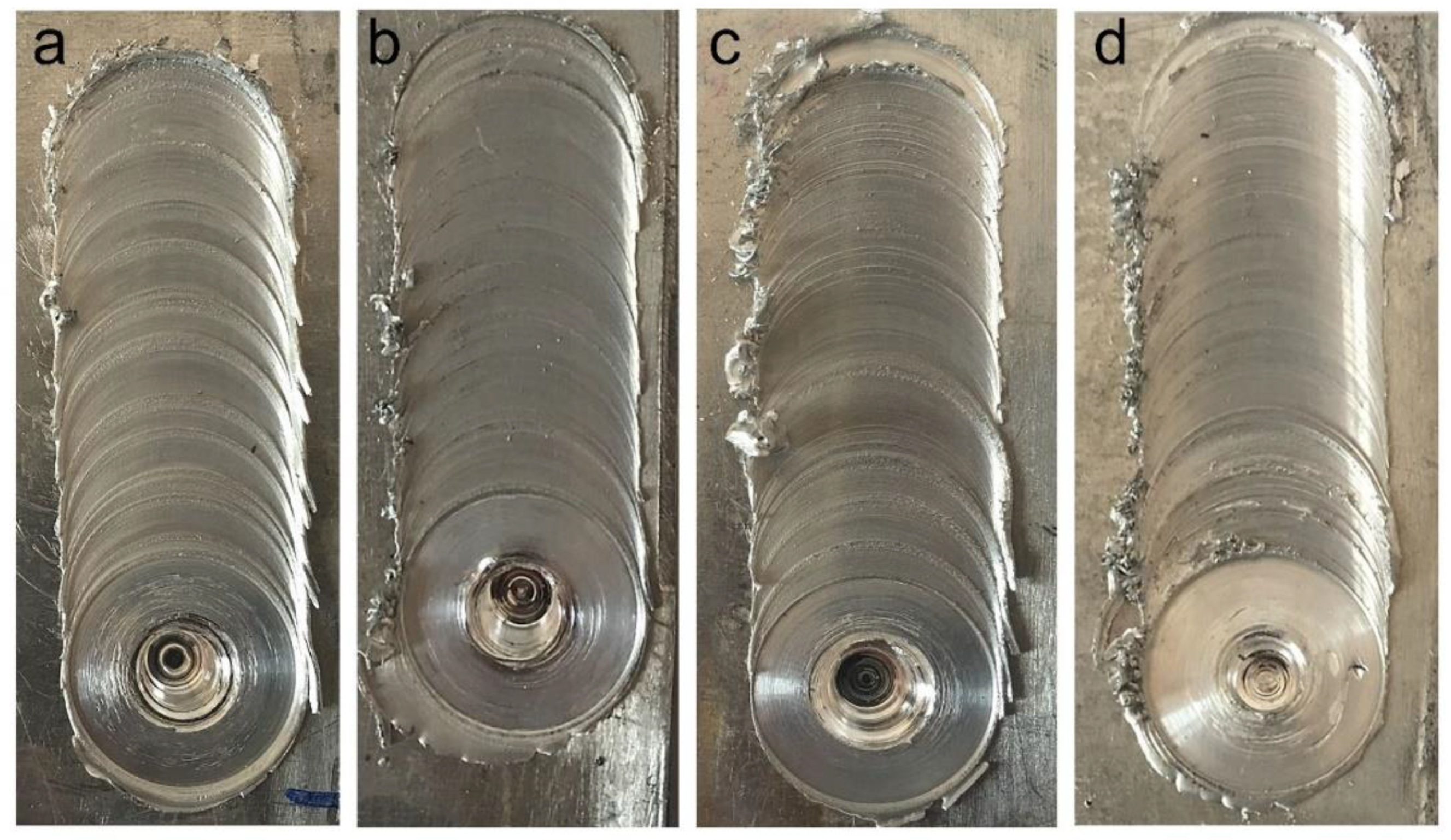
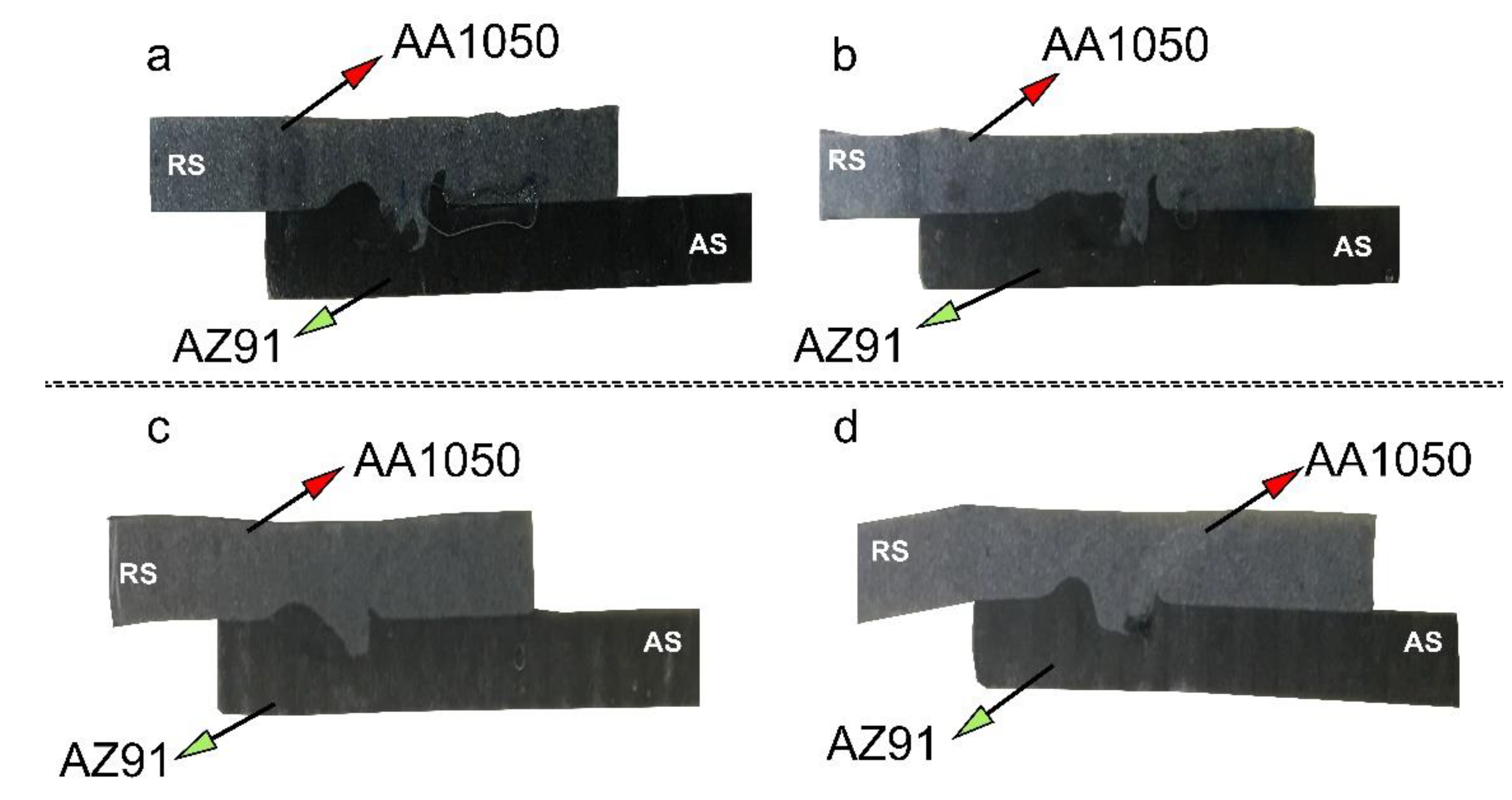
To visualize the welding appearance of samples, the top views of the joint zone for samples (A–D) are shown in Figure 2. Throughout Figure 2, no serious macro defects such as lack of connection, grooves, flashes, and warm defects appeared. Moreover, in the case of samples with rotation speed of 950 rpm, a small material outflow was observed. The cross-sections of the joints are presented in Figure 3 and the advancing side (AS) and retreating side (RS) are labeled. In all samples, AA1050 was dragged into the AZ91 layer at the center of the weld. In some samples, a hook can be observed in the retreating side in which AZ91 was dragged into the AA1050 layer.
It should be noted that one way to understand the chemical bonding mechanism between AA1050/AZ91 is their properties and incompatibility aspect. Generally, an impractical feature is a limited solubility governing the formation of IMCs which is explained by the binary phase diagram for these elements, see Figure 4 adapted from Ref. [7]. Nevertheless, the welding process is non-equilibrium, and to predicate the formation phases and possible reactions during welding, the equilibrium binary phase diagram is a standard guideline. Considering the fact that measuring the exact peak temperature during welding is almost impossible, using phase diagram is an acceptable method to envisage formation IMCs which depends on local temperature and composition. Throughout Figure 4, several phenomena can be comprehended: the binary system includes two eutectic lines at 437 and 450 °C which are lower than melting points of pure AA1050 and AZ91. Furthermore, three stable intermetallic phases including Al3Mg2 (complex cubic β) phase, Al12Mg17 (cubic of α-Mg type γ) phase and rhombohedral R phase exist [7,34].
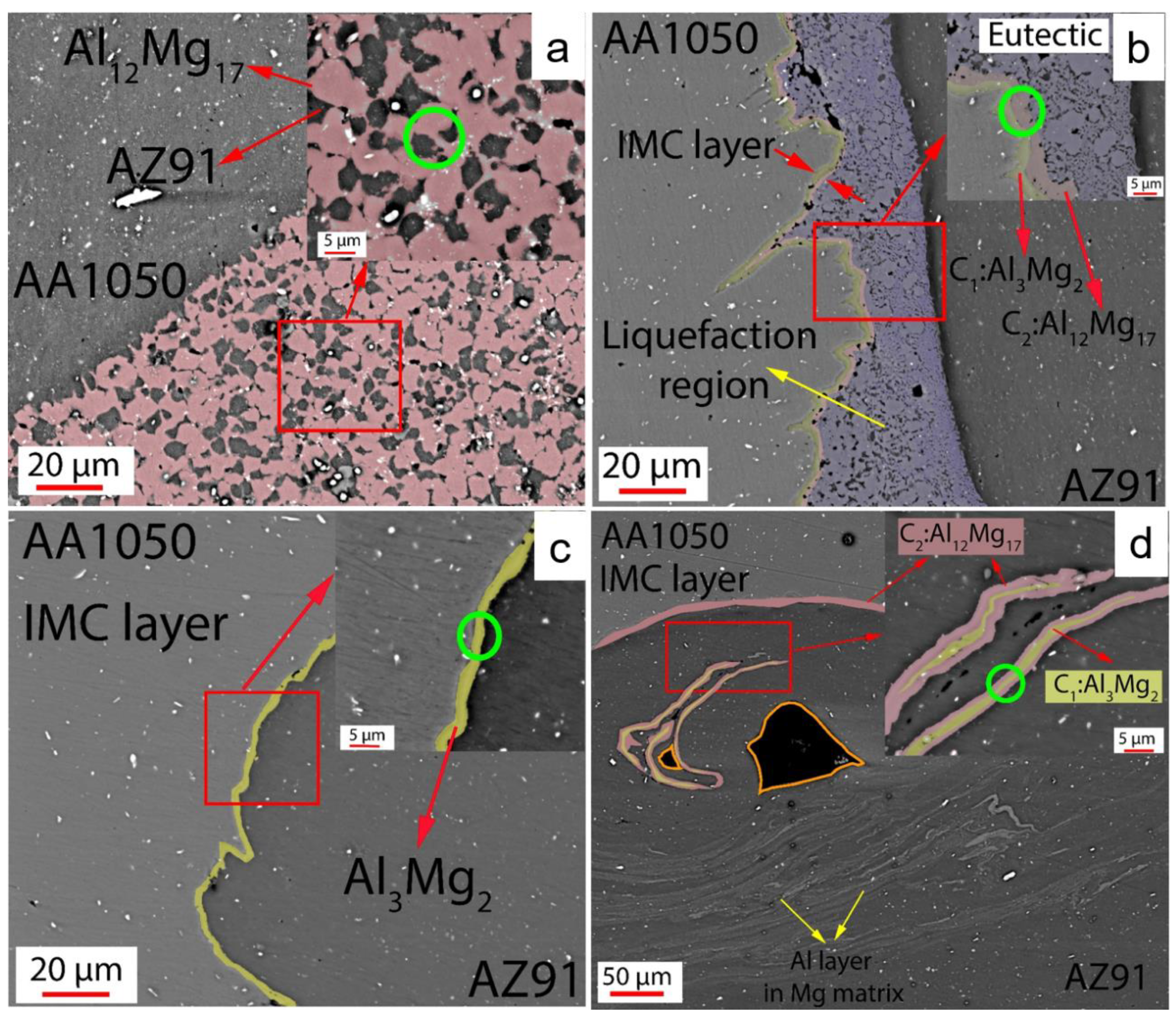
As stated, involved parameters have pivotal role on the formation of microstructure. In order to visualize heat input’s influence on the fracture behavior of the welds and find a correlation between welding parameters and joint strengths, the cross sections of the welds were studied by SEM in Figure 5. The SEM image of the weld nugget zone of sample A is shown in Figure 5a. A continuous layer of intermetallic compounds is not observed at the interface of AA1050 and AZ91. In Figure 5a, an SEM image of the interface at a higher magnification reveals the presence of a liquefaction region (highlighted in pink). This region appears to consist of two distinct phases. The SEM image of sample B is shown in Figure 5b at different magnifications revealing that the lamellar eutectic structures consisting of Mg + Al12Mg17 were formed at the AA1050/AZ91 interface. At the interface of AA1050 and AZ91, a region was observed which consists of a continuous bilayer IMC and a liquefaction layer. This is consistent with another report in which the eutectic layer was formed in the Mg-rich region [51]. It should be noted that the liquefaction leads to eutectic formation in the stir zone which possesses a different formation mechanism compared to IMCs [7]. The SEM interface of sample C is shown in Figure 5c, and a very thin continuous layer at the interface of AA1050 and AZ91 was observed. Figure 5d shows the SEM image of sample D, and a very thin continuous layer can be observed at the interface of AA1050 and AZ91. Comparing SEM images revealed that in sample D, a small cavity on the AS, which is colored in the orange region in the nugget zone, emerged. This is probably due to lower heat input resulting in insufficient mixing and plasticization of the materials.
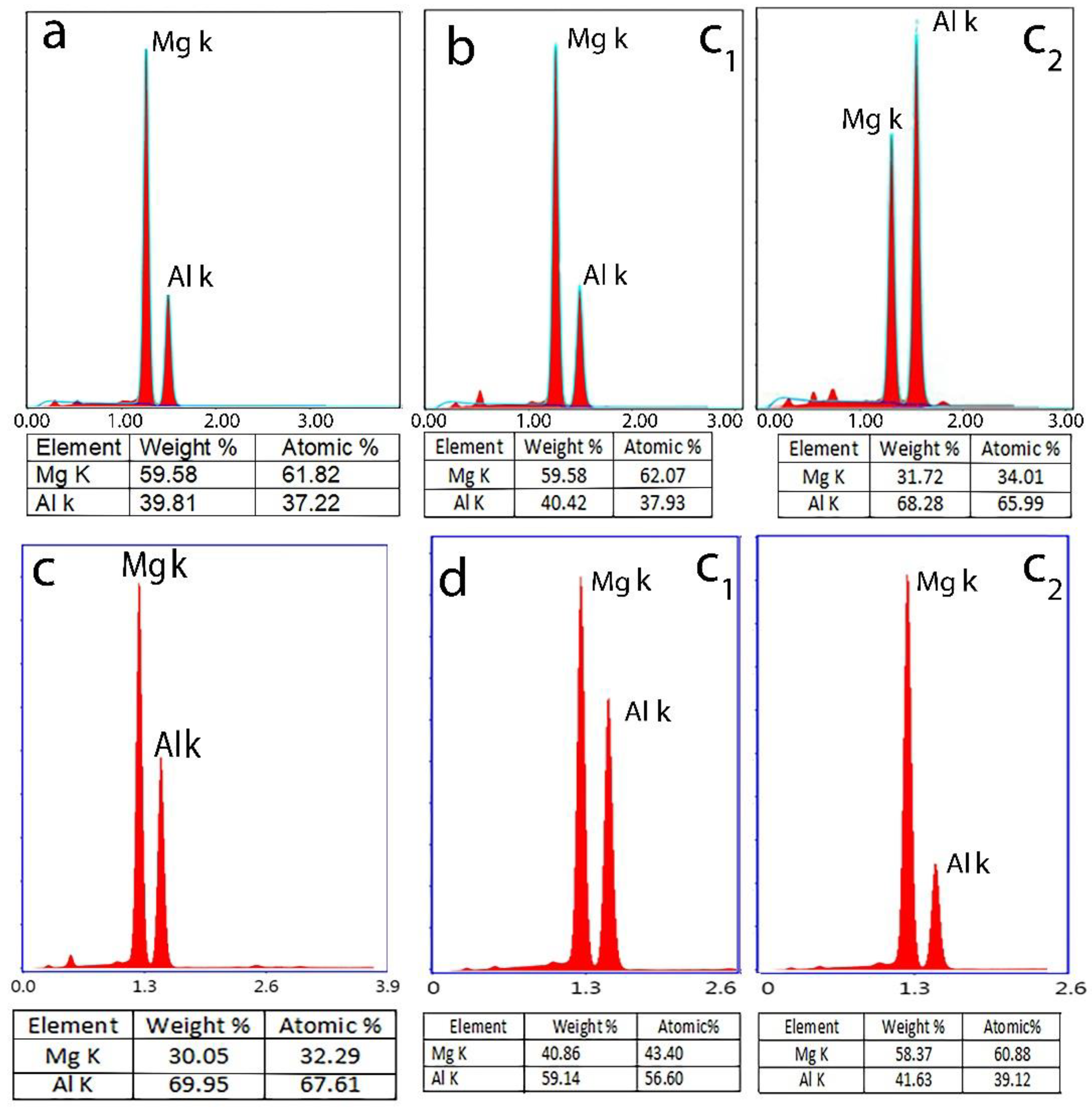
To study the chemical composition of samples, the EDS analysis of these regions shown in Figure 6 was performed from places indicated by the green circle in Figure 5. The EDS spectrum of sample A was depicted in Figure 6a, and the results suggest that this pink region is composed of a Mg–Al12Mg17 eutectic compound. The EDS analysis of the continuous IMC layer of sample B in Figure 6b shows that the liquefaction zone formed a eutectic phase which is composed of Mg and Al12Mg17 and a continuous layer consisting of Al12Mg17 and Al3Mg2 was formed adjacent to the Al layer. The EDS spectrum of sample c, as shown in Figure 6c, provides confirmation that at the interface of AA1050 and AZ91, the presence of Al3Mg2 has been detected, indicating the formation of a continuous layer. The EDS analysis of sample D, Figure 6d, revealed that Al12Mg17 was formed at the interface of AA1050 and AZ91. Moreover, fragments of AA1050-AZ91 intermetallic phases are dispersed in AZ91 matrix, whereas in AA1050 matrix dispersion of AA1050-AZ91, intermetallic phases cannot be detected.
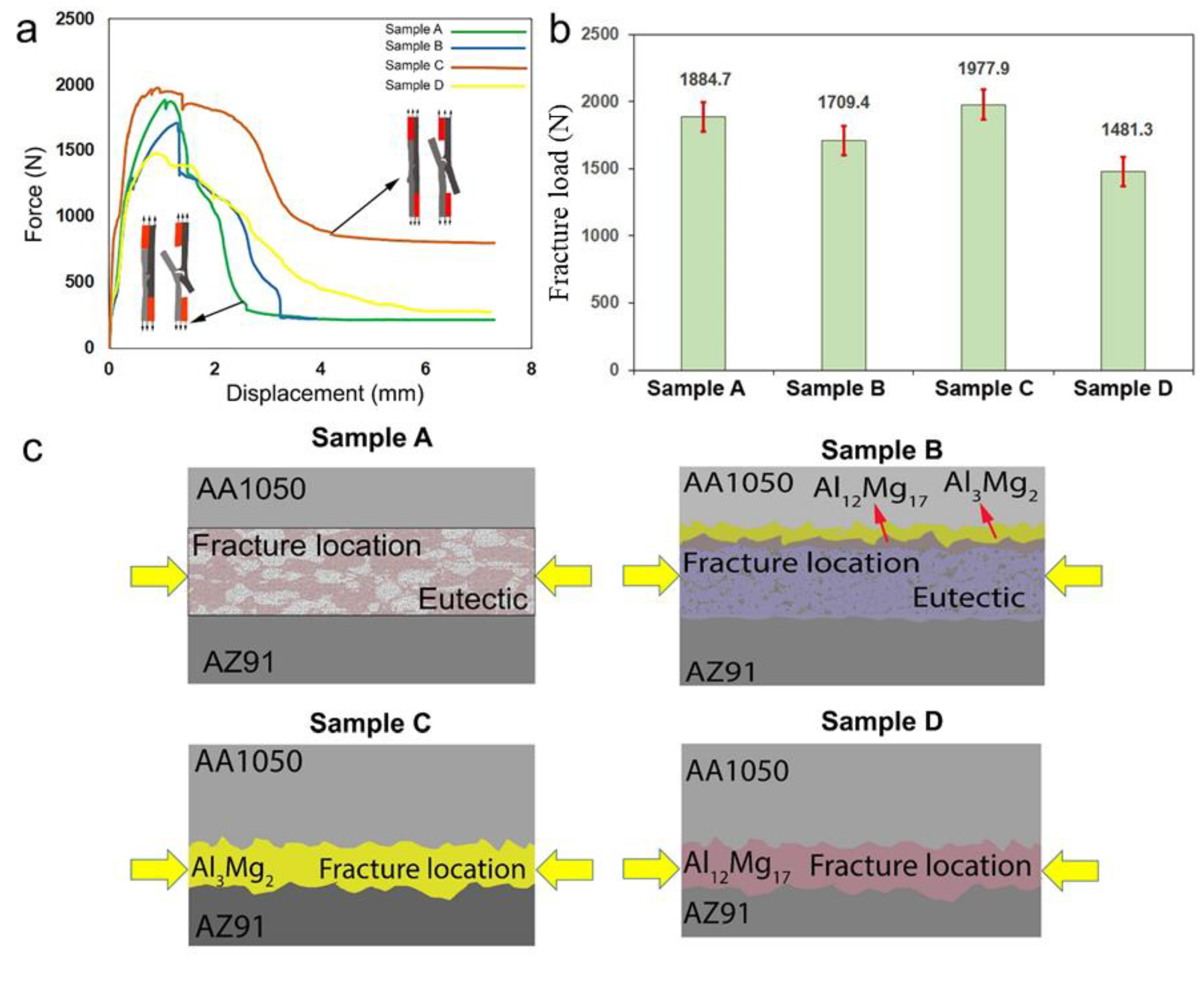
The formation of a brittle intermetallic compound (IMC) layer at the boundary between the base metals is the most critical issue that limits the strength of the dissimilar FSW joint between AA1050 and AZ91. The tensile test results, as a function of displacement, are presented in Figure 7a and the highest obtained UTS for samples is presented in Figure 7b. An illustration of the fracture path was schematized in Figure 7c. A great difference can be observed in some samples indicating that welding parameters influence the fracture strength. The fracture samples were precisely examined, and the fracture area was schematically shown in Figure 7c for all samples. It is noticeable that the fracture for sample A took place across the eutectic zone. Similar to sample A, the fracture in sample B was placed in the eutectic zone as shown schematically in Figure 7c. Despite the presence of a continuous layer of intermetallic compounds, the fracture did not occur through this layer due to a low thickness of this continuous IMC layer. In this sample, the liquation during welding caused a decrease in the friction coefficient which in turn decreased the heat generation during welding [34]. Furthermore, the formation of a eutectic microstructure impeded the growth of a thick IMC layer due to hindering diffusion and activity of elements which is consistent with another study [37]. Thus, it could be concluded that a lower local temperature during welding and eutectic formation leads to the formation of a thinner intermetallic compound at the interface. The illustration of the fracture place for sample C demonstrates that the fracture took place at the interface of Al3Mg2 and Mg. According to Figure 7c, for sample D, it can be seen that the fracture was propagated at the interface of Al12Mg17 and Mg. Some brittle regions at the fracture surface can be observed which is due to the dispersion of intermetallic phases in Mg matrix as seen in Figure 5d.
It is documented that the fracture location (Figure 7c) occurred through the bonding interface which is mainly attributed to presence of brittle IMCs at the Al/Mg interface, adversely affecting the joint quality. Meticulous investigation of tensile test of samples (Figure 7a) revealed that three types of trends can be derived: (1) when tool rotational speed is steady (i.e., samples A and B), a sample with lower welding traverse speed (sample A) shows a higher, ultimate tensile strength (UTS); (2) at constant welding traverse speed (i.e., samples A and C), the lower rotational speed (sample C) resulted in a higher UTS; and (3) when the fracture occurs through the eutectic region (sample B), the UTS is higher than when the fracture occurs within the IMCs layer (sample D).
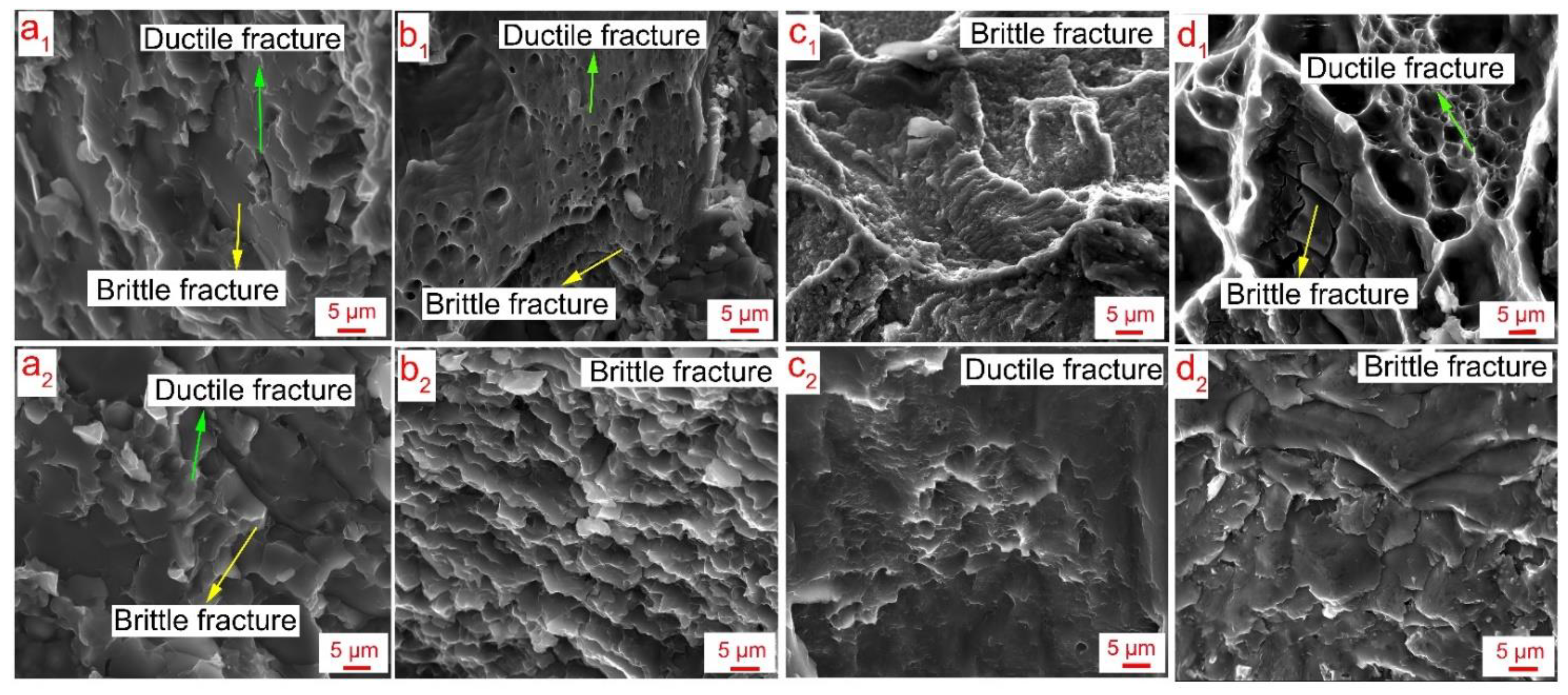
In order to realize the correlation between microstructure and fracture behavior, the fracture surfaces were investigated by SEM (Figure 8). A comparison of results reveals that fracture location initiation significantly impacts fracture morphology. Intermetallic compounds greatly influence fracture morphology in Al/Mg alloys. Because of their low fracture toughness, the IMCs are prone to cracking and breaking under load [17]. As EDS results proved, Al12Mg17 and Al3Mg2 are two intermetallic compounds detected at the interface of Al and Mg.
Figure 8(a1,a2) show the fracture surfaces of sample A from the AA1050 and AZ91 sides, respectively. The fracture surfaces indicate the presence of both ductile and brittle characteristics, resulting in a lamellar structure. The brittle fracture was observed in the Al12Mg17 intermetallic compound in the nugget zone. The failure of sample A occurred from the nugget zone, which includes the Mg phase and eutectic structure comprising the Mg and Al12Mg17 intermetallic compound, as shown in Figure 7c. The fracture surfaces of sample B are presented in Figure 8(b1,b2). The fracture surface of the AA1050 side shows the presence of both ductile and brittle characteristics, whereas the AZ91 side shows a completely brittle fracture. The brittle fracture occurred between the Al12Mg17 and Al3Mg2 intermetallic compounds on the Al side, whereas ductile fracture occurred in the AA1050 matrix. The brittle fracture occurred in the Al12Mg17 intermetallic compound on the Mg side. The brittle phase in both Al and Mg sides had the composition of Al12Mg17 and Al3Mg2. The failure of sample B occurred from the mixing zone, which includes the Mg phase and eutectic structure comprising the Mg and Al12Mg17 intermetallic compound, as shown in Figure 7c. The fracture surfaces of sample C are presented in Figure 8(c1,c2). The fracture surface of the Al side indicates a brittle fracture, whereas the Mg side shows a ductile fracture. The presence of intermetallic compounds Al3Mg2 caused a brittle failure in the welding zone. The failure of sample C occurred from within the mixing zone, which includes the Mg phase and intermetallic compound Al3Mg2. According to Figure 5c, the intermetallic compound formed in sample C is in the form of a continuous layer with very low thickness, resulting in the highest strength among the samples. The arrangement of the different phases at the junction is shown in Figure 7c. The fracture surface of sample C is soft, and the strength is very high due to the thinness of the intermetallic compounds, which caused the fracture strength of the weld to exceed the yield strength of the aluminum. Before the weld failure, the base Al experienced some plastic deformation, with a force required to yield Al in this state equal to N 2025 (15 × 3 × 45), resulting in high deformation. The fracture surfaces of sample D are depicted in Figure 8(d1,d2). The fracture surface of the AA1050 side indicated the presence of both ductile and brittle characteristics, with the Al12Mg17 composition observed on the fracture surface. The recoil of Al12Mg17 was higher on the Al side than on the Mg side, resulting in ductile failure in some areas but often in brittle fractures at the joint. On the other hand, the fracture on the AZ91 side was completely brittle and from the grain boundary. The failure of sample D occurred between the Mg and Al12Mg17 intermetallic compound, which is continuously formed at the weld boundary, as shown in Figure 5d.
Overall, the presence of intermetallic compounds and the lamellar structure resulted in brittle fracture in some areas, whereas the presence of ductile fracture in other areas is likely due to the plastic deformation of the aluminum matrix. These findings suggest that the microstructure and composition of the materials play a crucial role in determining the fracture behavior of the welded samples.
From the shear-tensile test and fracture morphology, it could be concluded that the relation between brittle fracture and crack propagation is associated with the formed brittle IMCs at the stir interface of AA1050/AZ91, which is consistent with other reports [52,53,54].
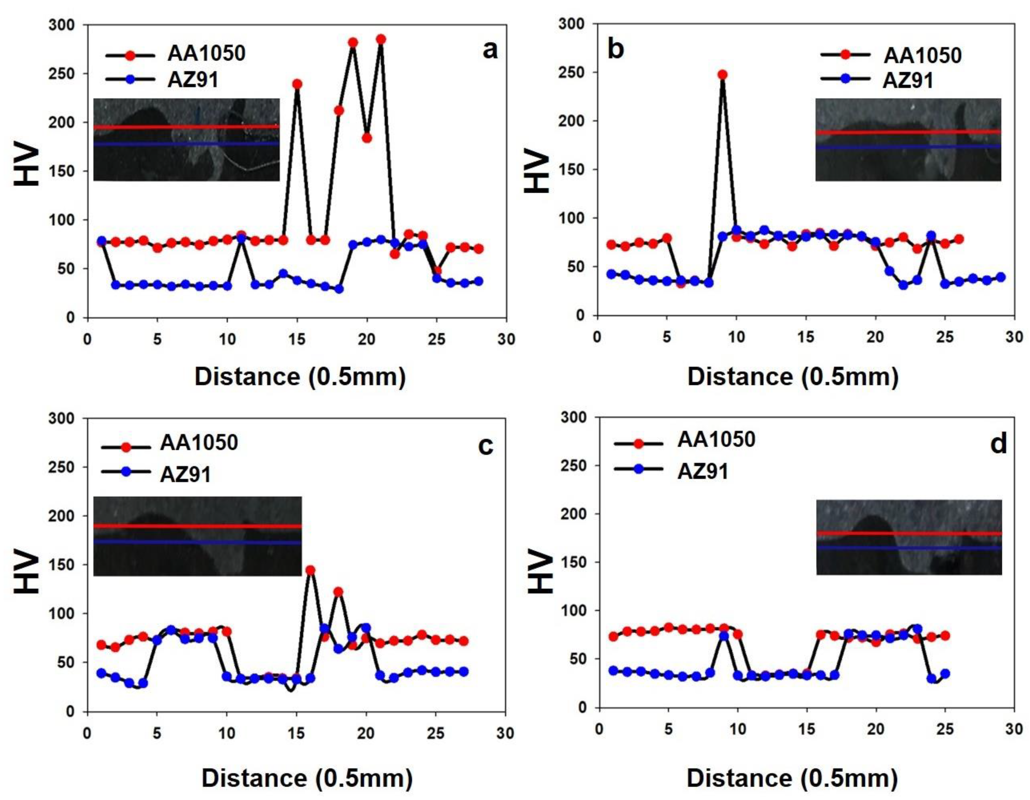
The microhardness distribution across the weld line is shown in Figure 9. The microhardness results show an increase in hardness within the welding zone, followed by a rapid decrease as one moves away from the central weld location. Two distinct hardness distribution profiles were evident on either side.
Throughout Figure 9, the results indicate that the Al side of sample A has the highest hardness. The presence of intermetallic compounds in the nugget zone caused a sudden increase in hardness in the weld zone, and the accumulation of these compounds resulted in higher hardness compared to the base metal. Furthermore, Figure 9a,b revealed that there was a significant increase in hardness in some locations, which is probably due to the formation of eutectic in the stir zone. The coincidence of hardness values in AA1050 and AZ91 is attributed to drag of the layers into each other. Though SEM analysis revealed the presence of intermetallic compounds such as Al2Mg3 and Al12Mg17 at the welding boundary in samples C and D, the hardness values are lower in these samples. This is due to two factors. First, the volume of IMCs formed in these samples is lower and second, the IMCs layers are thin and dispersed in the matrix.
Considering the discussed results, the correlation between mechanical properties of the joint and welding parameters can be explained as follows:
At a low rotation rate of the tool, a thin intermetallic compound forms at the Al-Mg interface due to the low heat generation. Therefore, a high level of weld strength can be obtained. In our cases, the fracture surface is almost composed of brittle material.
At a high tool rotation speed, a severe mixing of Al and Mg occurs in the stir zone. The severe mixing along with the high local temperature results in local diffusivity of Al and Mg which in turn promotes liquid Al12Mg17-Mg eutectic compound formation. The formation of this liquid compound decreases the friction coefficient between the tool and the material; consequently, the temperature during welding decreases. This decline in the intermetallic growth leads to the formation of a very thin layer of Al-Mg intermetallic compounds at the interface. Whereas this eutectic layer consists of brittle (Al12Mg17) and ductile (Mg) layers, the fracture takes place in this region. The EDS study of the fracture mode confirmed the presence of a mixture of ductile and brittle materials.

4. Conclusions

In this study, the influences of FSW welding parameters (welding traverse speed and tool rotation speed) on the weld strength of AA1050 to AZ91 were investigated. To visualize the formation of eutectic and liquefaction structures at the interface of AA1050 and AZ91, SEM and EDS analyses were applied. The main results obtained by friction stir lap welding of AA1050/AZ91 are listed as follows:
  • The tool rotation speed plays a major role in the joint quality and intermetallic compounds;
  • At low rotation speed of the tool, a thin intermetallic layer forms at the interface, and the joint strength is the highest among all the parameters. The fracture propagates through the AZ91 layer;
  • At high rotation speed, liquation takes place in the weld nugget which is composed of a eutectic compound. This liquation causes the slippage of the tool and lowers the heat generation during welding. Moreover, the diffusion rate of elements decreases due to the existence of the eutectic layer. Hence, a thin layer of intermetallic compound forms at the interface. The fracture propagates through the eutectic compound;
  • At a higher welding traverse speed with a lower rotational speed, insufficient frictional local heat input and lower exposure time lead to inadequate metallurgical bonding at the AA1050-AZ91 interface. Some defects are observed in this sample due to insufficient material flow;
  • The results suggested that rotation rate affects the formation of eutectic structures at the interface;
  • The formation of eutectic compounds is influenced by the rotation speed, which is not related to the advanced speed at higher rotation speeds;
  • When aluminum penetrates magnesium, it enhances the hardness of the magnesium, whereas magnesium infiltration in aluminum decreases the hardness of the aluminum;
  • The formation of eutectic compositions plays a significant role in ensuring consistent hardness levels.

Author Contributions

Conceptualization, R.B.; Investigation, K.T.; Writing—original draft, K.T.; Writing—review & editing, R.B. and G.E.B.; Supervision, L.F.M.d.S. All authors have read and agreed to the published version of the manuscript.

Funding

The authors gratefully thank Arak University for supporting this project. The authors also acknowledge funding under the reference “UIDP/50022/2020—LAETA—Laboratório Associado de Energia, Transportes e Aeronáutica”.

Conflicts of Interest

The authors declare no conflict of interest.

References

  1. Thirumoorthy, A.; Arjunan, T.; Kumar, K.S. Latest research development in aluminum matrix with particulate reinforcement composites—A review. Mater. Today Proc. 2018, 5, 1657–1665. [Google Scholar] [CrossRef]
  2. Ng, C.; Yahaya, S.; Majid, A. Reviews on aluminum alloy series and its applications. J. Acad. Ind. Res. 2017, 5, 708–716. [Google Scholar]
  3. Baghdadi, A.H.; Rajabi, A.; Selamat, N.F.M.; Sajuri, Z.; Omar, M.Z. Effect of post-weld heat treatment on the mechanical behavior and dislocation density of friction stir welded Al6061. Mater. Sci. Eng. A 2019, 754, 728–734. [Google Scholar] [CrossRef]
  4. He, L.; Pan, L.; Zhou, W.; Niu, Z.; Chen, X.; Chen, M.; Zhang, Q.; Pan, W.; Xiao, P.; Li, Y. Thermal corrosion behavior of Yb4Hf3O12 ceramics exposed to calcium-ferrum-alumina-silicate (CFAS) at 1400 °C. J. Eur. Ceram. Soc. 2023, 43, 4114–4123. [Google Scholar] [CrossRef]
  5. Pan, L.; He, L.; Niu, Z.; Xiao, P.; Zhou, W.; Li, Y. Corrosion behavior of ytterbium hafnate exposed to water-vapor with Al(OH)3 impurities. J. Eur. Ceram. Soc. 2023, 43, 612–620. [Google Scholar] [CrossRef]
  6. Beygi, R.; Talkhabi, A.A.; Mehrizi, M.Z.; Marques, E.A.; Carbas, R.J.; da Silva, L.F. A Novel Lap-Butt Joint Design for FSW of Aluminum to Steel in Tee-Configuration: Joining Mechanism, Intermetallic Formation, and Fracture Behavior. Metals 2023, 13, 1027. [Google Scholar] [CrossRef]
  7. Singh, V.P.; Patel, S.K.; Ranjan, A.; Kuriachen, B. Recent research progress in solid state friction-stir welding of aluminium–magnesium alloys: A critical review. J. Mater. Res. Technol. 2020, 9, 6217–6256. [Google Scholar] [CrossRef]
  8. Zhou, C.; Yang, X.; Luan, G. Effect of root flaws on the fatigue property of friction stir welds in 2024-T3 aluminum alloys. Mater. Sci. Eng. A 2006, 418, 155–160. [Google Scholar] [CrossRef]
  9. Laska, A.; Szkodo, M.; Cavaliere, P.; Perrone, A. Influence of the Tool Rotational Speed on Physical and Chemical Properties of Dissimilar Friction-Stir-Welded AA5083/AA6060 Joints. Metals 2022, 12, 1658. [Google Scholar] [CrossRef]
  10. Shelley, T. Joining forces for multiple properties. Eureka 2003. [Google Scholar]
  11. Habibnia, M.; Shakeri, M.; Nourouzi, S.; Givi, M.B. Microstructural and mechanical properties of friction stir welded 5050 Al alloy and 304 stainless steel plates. Int. J. Adv. Manuf. Technol. 2015, 76, 819–829. [Google Scholar] [CrossRef]
  12. Liu, Q.; Han, R.; Gao, Y.; Ke, L. Numerical investigation on thermo-mechanical and material flow characteristics in friction stir welding for aluminum profile joint. Int. J. Adv. Manuf. Technol. 2021, 114, 2457–2469. [Google Scholar] [CrossRef]
  13. Gaurav, S.; Mishra, R.; Zunaid, M. A critical review on mechanical and microstructural properties of dissimilar aluminum (Al)-magnesium (Mg) alloys. J. Adhes. Sci. Technol. 2022, 1–33. [Google Scholar] [CrossRef]
  14. Fu, B.; Qin, G.; Li, F.; Meng, X.; Zhang, J.; Wu, C. Friction stir welding process of dissimilar metals of 6061-T6 aluminum alloy to AZ31B magnesium alloy. J. Mater. Process. Technol. 2015, 218, 38–47. [Google Scholar] [CrossRef]
  15. Xu, Y.; Ke, L.; Mao, Y.; Yang, P.; Niu, P. Friction stir welding of aluminium to magnesium: A critical review. Mater. Sci. Technol. 2022, 38, 517–534. [Google Scholar] [CrossRef]
  16. Elangovan, K.; Balasubramanian, V.; Valliappan, M. Effect of tool pin profile and tool rotational speed on mechanical properties of friction stir welded AA6061 aluminium alloy. Mater. Manuf. Process. 2008, 23, 251–260. [Google Scholar] [CrossRef]
  17. Nonnenmann, T.; Beygi, R.; Carbas, R.J.; da Silva, L.F.; Öchsner, A. Feasibility study on hybrid weld-bonding between dissimilar material for automotive industry. Int. J. Adhes. Adhes. 2023, 121, 103316. [Google Scholar] [CrossRef]
  18. Safeen, M.W.; Russo Spena, P. Main issues in quality of friction stir welding joints of aluminum alloy and steel sheets. Metals 2019, 9, 610. [Google Scholar] [CrossRef] [Green Version]
  19. El-Sayed, M.M.; Shash, A.; Abd-Rabou, M.; ElSherbiny, M.G. Welding and processing of metallic materials by using friction stir technique: A review. J. Adv. Join. Process. 2021, 3, 100059. [Google Scholar] [CrossRef]
  20. Meschut, G.; Merklein, M.; Brosius, A.; Drummer, D.; Fratini, L.; Füssel, U.; Gude, M.; Homberg, W.; Martins, P.; Bobbert, M. Review on mechanical joining by plastic deformation. J. Adv. Join. Process. 2022, 5, 100113. [Google Scholar] [CrossRef]
  21. Mohammadi, J.; Behnamian, Y.; Mostafaei, A.; Izadi, H.; Saeid, T.; Kokabi, A.; Gerlich, A. Friction stir welding joint of dissimilar materials between AZ31B magnesium and 6061 aluminum alloys: Microstructure studies and mechanical characterizations. Mater. Charact. 2015, 101, 189–207. [Google Scholar] [CrossRef]
  22. Shi, L.; Wu, C. Transient model of heat transfer and material flow at different stages of friction stir welding process. J. Manuf. Process. 2017, 25, 323–339. [Google Scholar] [CrossRef]
  23. Husain, M.M.; Sarkar, R.; Pal, T.; Prabhu, N.; Ghosh, M. Friction stir welding of steel: Heat input, microstructure, and mechanical property co-relation. J. Mater. Eng. Perform. 2015, 24, 3673–3683. [Google Scholar] [CrossRef]
  24. Krishnan, M.; Subramaniam, S.K. Investigation of mechanical and metallurgical properties of friction stir corner welded dissimilar thickness AA5086-AA6061 aluminium alloys. Mater. Res. 2018, 21. [Google Scholar] [CrossRef]
  25. Liu, F.; Fu, L.; Chen, H. Effect of high rotational speed on temperature distribution, microstructure evolution, and mechanical properties of friction stir welded 6061-T6 thin plate joints. Int. J. Adv. Manuf. Technol. 2018, 96, 1823–1833. [Google Scholar] [CrossRef]
  26. Salih, O.S.; Ou, H.; Wei, X.; Sun, W. Microstructure and mechanical properties of friction stir welded AA6092/SiC metal matrix composite. Mater. Sci. Eng. A 2019, 742, 78–88. [Google Scholar] [CrossRef]
  27. Buffa, G.; Baffari, D.; Di Caro, A.; Fratini, L. Friction stir welding of dissimilar aluminium–magnesium joints: Sheet mutual position effects. Sci. Technol. Weld. Join. 2015, 20, 271–279. [Google Scholar] [CrossRef]
  28. Liu, H.; Fujii, H.; Maeda, M.; Nogi, K. Mechanical properties of friction stir welded joints of 1050–H24 aluminium alloy. Sci. Technol. Weld. Join. 2003, 8, 450–454. [Google Scholar] [CrossRef]
  29. Beygi, R.; Akhavan-Safar, A.; Carbas, R.; Barbosa, A.; Marques, E.; da Silva, L. Utilizing a ductile damage criterion for fracture analysis of a dissimilar aluminum/steel joint made by friction stir welding. Eng. Fract. Mech. 2022, 274, 108775. [Google Scholar] [CrossRef]
  30. Zhao, Y.; Jiang, S.; Yang, S.; Lu, Z.; Yan, K. Influence of cooling conditions on joint properties and microstructures of aluminum and magnesium dissimilar alloys by friction stir welding. Int. J. Adv. Manuf. Technol. 2016, 83, 673–679. [Google Scholar] [CrossRef]
  31. Lv, X.; Wu, C.; Padhy, G. Diminishing intermetallic compound layer in ultrasonic vibration enhanced friction stir welding of aluminum alloy to magnesium alloy. Mater. Lett. 2017, 203, 81–84. [Google Scholar] [CrossRef]
  32. Kumar, N.; Yuan, W.; Mishra, R. Challenges and opportunities for friction stir welding of dissimilar alloys and materials (Chapter 7). In Friction Stir Welding of Dissimilar Alloys and Materials; Elsevier Butterworth-Heinemann: Oxford, UK, 2015; pp. 123–126. [Google Scholar]
  33. Paul, A.R.; Mukherjee, M.; Singh, D. A critical review on the properties of intermetallic compounds and their application in the modern manufacturing. Cryst. Res. Technol. 2022, 57, 2100159. [Google Scholar] [CrossRef]
  34. Shah, L.; Othman, N.; Gerlich, A. Review of research progress on aluminium–magnesium dissimilar friction stir welding. Sci. Technol. Weld. Join. 2018, 23, 256–270. [Google Scholar] [CrossRef]
  35. Yang, Y.; Dong, H.; Kou, S. Liquation tendency and liquid-film formation in friction stir spot welding. Weld. J. 2008, 87, 202S–211S. [Google Scholar]
  36. Yamamoto, N.; Liao, J.; Watanabe, S.; Nakata, K. Effect of intermetallic compound layer on tensile strength of dissimilar friction-stir weld of a high strength Mg alloy and Al alloy. Mater. Trans. 2009, 50, 2833–2838. [Google Scholar] [CrossRef] [Green Version]
  37. Firouzdor, V.; Kou, S. Al-to-Mg friction stir welding: Effect of positions of Al and Mg with respect to the welding tool. Weld. J. 2009, 88, 213–224. [Google Scholar]
  38. Prabha, K.A.; Putha, P.K.; Prasad, B.S. Effect of tool rotational speed on mechanical properties of aluminium alloy 5083 weldments in friction stir welding. Mater. Today Proc. 2018, 5, 18535–18543. [Google Scholar] [CrossRef]
  39. Ji, S.; Meng, X.; Liu, Z.; Huang, R.; Li, Z. Dissimilar friction stir welding of 6061 aluminum alloy and AZ31 magnesium alloy assisted with ultrasonic. Mater. Lett. 2017, 201, 173–176. [Google Scholar] [CrossRef]
  40. Rao, H.; Yuan, W.; Badarinarayan, H. Effect of process parameters on mechanical properties of friction stir spot welded magnesium to aluminum alloys. Mater. Des. 2015, 66, 235–245. [Google Scholar] [CrossRef] [Green Version]
  41. Firouzdor, V.; Kou, S. Al-to-Mg friction stir welding: Effect of material position, travel speed, and rotation speed. Metall. Mater. Trans. A 2010, 41, 2914–2935. [Google Scholar] [CrossRef]
  42. Beygi, R.; Zarezadeh Mehrizi, M.; Akhavan-Safar, A.; Mohammadi, S.; da Silva, L.F. A Parametric Study on the Effect of FSW Parameters and the Tool Geometry on the Tensile Strength of AA2024–AA7075 Joints: Microstructure and Fracture. Lubricants 2023, 11, 59. [Google Scholar] [CrossRef]
  43. Kumar, U.; Acharya, U.; Saha, S.C.; Saha Roy, B. Microstructure and mechanical property of friction stir welded Al-Mg joints by adopting modified joint configuration technique. Mater. Today Proc. 2020, 26, 2083–2088. [Google Scholar] [CrossRef]
  44. Wu, H.; Chen, Y.-C.; Strong, D.; Prangnell, P. Stationary shoulder FSW for joining high strength aluminum alloys. J. Mater. Process. Technol. 2015, 221, 187–196. [Google Scholar] [CrossRef]
  45. Beygi, R.; Pouraliakbar, H.; Torabi, K.; Fallah, V.; Kim, S.; Shi, R.; da Silva, L. The inhibitory effect of stir zone liquefaction and eutectic-phase formation on the growth of γ/β intermetallics during dissimilar FSW of Al/Mg alloys. J. Manuf. Process. 2021, 70, 152–162. [Google Scholar] [CrossRef]
  46. Ji, S.; Li, Z.; Zhang, L.; Zhou, Z.; Chai, P. Effect of lap configuration on magnesium to aluminum friction stir lap welding assisted by external stationary shoulder. Mater. Des. 2016, 103, 160–170. [Google Scholar] [CrossRef]
  47. Ghiasvand, A.; Ranjbarnodeh, E.; Mirsalehi, S.E. The microstructure and mechanical properties of single-pass and double-pass lap joint of Al 5754H-11 and Mg AZ31-O alloys by friction stir welding. J. Mater. Res. Technol. 2023, 23, 6023–6038. [Google Scholar] [CrossRef]
  48. Akbari, M.; Aliha, M.; Keshavarz, S.; Bonyadi, A. Effect of tool parameters on mechanical properties, temperature, and force generation during FSW. Proc. Inst. Mech. Eng. Part L J. Mater. Des. Appl. 2019, 233, 1033–1043. [Google Scholar] [CrossRef]
  49. Mao, Y.; Yang, P.; Zhang, W.; Li, N.; Nie, H.; Lin, D.; Ke, L. Improving tensile-shear properties of friction stir lap welded dissimilar Al/Mg joints by eliminating hook defect and controlling interfacial reaction. Chin. J. Aeronaut. 2022, in press. [Google Scholar] [CrossRef]
  50. Lakshminarayanan, A.; Annamalai, V. Fabrication and performance evaluation of dissimilar magnesium–aluminium alloy multi-seam friction stir clad joints. Trans. Nonferrous Met. Soc. China 2017, 27, 25–35. [Google Scholar] [CrossRef]
  51. Chen, W.; Wang, W.; Liu, Z.; Zhai, X.; Bian, G.; Zhang, T.; Dong, P. Improvement in tensile strength of Mg/Al alloy dissimilar friction stir welding joints by reducing intermetallic compounds. J. Alloys Compd. 2021, 861, 157942. [Google Scholar] [CrossRef]
  52. Sato, Y.S.; Park, S.H.C.; Michiuchi, M.; Kokawa, H. Constitutional liquation during dissimilar friction stir welding of Al and Mg alloys. Scr. Mater. 2004, 50, 1233–1236. [Google Scholar] [CrossRef]
  53. Jagadeesha, C. Dissimilar friction stir welding between aluminum alloy and magnesium alloy at a low rotational speed. Mater. Sci. Eng. A-Struct. Mater. Prop. Microstruct. Process. 2014, 616, 55–62. [Google Scholar] [CrossRef]
  54. Shi, H.; Chen, K.; Liang, Z.; Dong, F.; Yu, T.; Dong, X.; Zhang, L.; Shan, A. Intermetallic compounds in the banded structure and their effect on mechanical properties of Al/Mg dissimilar friction stir welding joints. J. Mater. Sci. Technol. 2017, 33, 359–366. [Google Scholar] [CrossRef]
Figure 1. An illustration of the welding process representing the geometry of the tool and the location of the samples for the performed tests. The lap configuration was Al/Mg and the tool was inserted into Al. The advancing side was placed in aluminum. The length of the weld was 100 mm.
Applsci 13 07133 g001
Figure 2. (ad) Top views of the welds zone of AA1050/AZ91 joints for A–D samples, respectively. (Welding condition was introduced in Table 3).
Applsci 13 07133 g002
Figure 3. (ad) The cross-sections of the joints for A–D samples, respectively. (Welding condition was introduced in Table 3).
Applsci 13 07133 g003
Figure 4. Equilibrium phase diagram of Al-Mg system [7].
Applsci 13 07133 g004
Figure 5. The SEM images of (ad) sample A–D, respectively. The continuous layer, liquefaction region, and eutectic structure were marked in the panels. In panel (d), a formed cavity is highlighted in orange.
Applsci 13 07133 g005
Figure 6. (ad) The EDS spectrum of A–D, respectively. The C1 and C2 in panel (b,d) represent the EDS of regions shown in Figure 5b and Figure 5d, respectively.
Applsci 13 07133 g006
Figure 7. (a) Examined shear stress-displacement diagram of the shear-tensile tests of welded samples, (b) bar chart demonstrating obtained maximum UTS for samples, and (c) a schematic illustration of fracture location in sample A–D.
Applsci 13 07133 g007
Figure 8. SEM image of (a1d1) Al side and (a2d2) Mg side of the fracture surface from samples A-D, respectively.
Applsci 13 07133 g008
Figure 9. (ad) Hardness profile of the joints for sample A–D. The insect picture in panels show the microhardness measurement line of specimens (red line: AA1050 side and blue line: AZ91 side).
Applsci 13 07133 g009
Table 1. Chemical composition of AA1050 (wt%).
AlVZnMnFeSiCu
Balance0.0100.0500.0500.420.20.08
Table 2. Chemical composition of AZ91 (wt%).
MgFeSiNiCuMnZnAlCa
Balance0.0050.30.0050.0510.2020.4038.140.577
Table 3. The welding parameters used for friction stir lap welding of AA1050/AZ91.
SampleWelding Speed (mm/min)Tool Rotation Speed (rpm)
A23.5950
B37.5950
C23.5600
D37.5600
Disclaimer/Publisher’s Note: The statements, opinions and data contained in all publications are solely those of the individual author(s) and contributor(s) and not of MDPI and/or the editor(s). MDPI and/or the editor(s) disclaim responsibility for any injury to people or property resulting from any ideas, methods, instructions or products referred to in the content.