Abstract
As a high-quality building material exhibiting excellent toughness and durability, ultrahigh-performance concrete (UHPC) is increasingly being used in the construction industry and as building reinforcement. During the reinforcement of existing concrete structures with UHPC, their interface is the weakest part of a structure. Interface bonding ensures the operation of two types of materials together. However, existing studies rarely report the bonding of the UHPC–normal concrete (NC) interface. Herein, the existing test methods and interface bonding mechanisms are summarized. Subsequently, the differences among relevant design codes are investigated by comparing different theoretical formulas. Important influencing factors of the reinforcement method, namely, interface roughness, fiber type and content, interface agent type and content, moisture content, existing concrete strength, cementitious material content, curing conditions, freeze–thaw cycles, and chloride ions, are also considered. Further, the enhancement mechanism of the characteristics of the UHPC–NC interface is clearly described. Finally, the shortcomings and application prospects of the interfacial bonding properties are highlighted.
1. Introduction
Normal concrete (NC) is a material with low strength and poor resistance under harsh environments, whereas ultrahigh-performance concrete (UHPC) is a cement-based composite material with a low water-to-binder ratio, low porosity, good homogeneity, and ideal compactness. As a building material, UHPC has ultrahigh strength, excellent durability, toughness, and good ductility because of its fiber inclusions [1,2,3,4,5,6,7,8]. As such, it is widely used in bridge structures and ocean engineering and is gradually being used in composite structures and as reinforcement for existing structures [9,10]. Previous studies have demonstrated that the interface connection between different structures or materials is the weakest part of a structure. Further, it is the location where failure starts and propagates to the other parts of the structure [11,12].
Generally, UHPC and NC should co-load and coordinate deformation in UHPC–NC composite structures [13,14,15,16], wet joint filling [17,18,19], and existing structure reinforcements [20,21,22,23]. Good bonding between these two materials is critical for ensuring the reinforcement effect. UHPC improves the overall mechanical performance, limits the invasion of harmful substances, and improves the service life of structures.
This paper summarizes the existing interface bonding strength tests, as well as the theoretical calculations and influencing factors of the shear strength of the interface bonding zone of UHPC–NC composites. Moreover, the shortcomings of previous studies are presented, and future research directions to guide the application of UHPC to strengthen existing structures are discussed.
2. UHPC–NC Interfacial Bonding Strength Test
For a UHPC–NC composite structure, the interface zone is commonly subjected to complex stresses, which comprise bending stress, pure shear stress, tensile and shear stress, and compressive and shear stress. Accordingly, the interface bonding strength of UHPC–NC should be evaluated. Several methods are employed to analyze the interface bonding strength, including the direct tensile test, pull-off test with core drilling, splitting test, direct shear test, slant shear test, and bending test [24].
2.1. Direct Tensile Test
The tensile tests for interface bonding strength are categorized into direct and indirect tensile tests [25,26]. The direct tensile test uses simple equipment and is easy to implement. Figure 1 shows the specimen shape and test load method for the direct tensile test. Feng [27] tested the interface bonding strength of wet joints using a direct tensile specimen; however, the eccentric load for the test was defective, affecting the reliability of the results. Zhang [28] and Hussein [29] reduced the eccentric load by installing rotatable ball hinges at the ends of the anchor. In addition, there is a considerable size effect in the softened segment of the stress–strain curve obtained using direct tensile tests. The softened segment cannot be regarded as a pure material, thereby affecting the reliability of the test results.
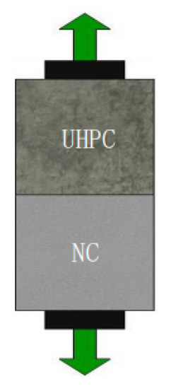
Figure 1.
Schematic of the direct tensile test.
2.2. Pull-Off Test with Core Drilling
Hussein [29], Carbonell [30], Sprinkel [31], and Tayeh [32] conducted pull-off tests with core drilling to measure the interface bonding strength of UHPC–NC. In these tests, the drilling core equipment directly extracts a core sample to address the limitations of the direct tensile test. The specimen shape and test method for the pull-off test are shown in Figure 2.
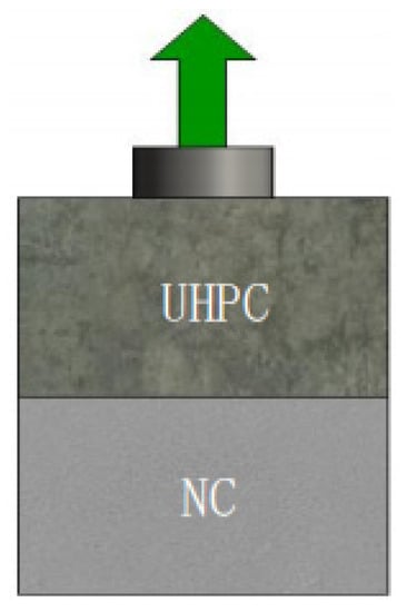
Figure 2.
Schematic of the pull-off test.
Experiments have primarily noted three failure modes in the UHPC–NC interface bonding zone [29]: substrate, interface, and overburden failures (Figure 3). The interface bonding strength of a specimen is measured in the interfacial failure mode. For the other two failure modes, the tensile strength instead of the interface bonding strength of the material is obtained because of the effects of the existing concrete strength, concrete aggregate, reinforcement layer thickness, core depth and diameter, and eccentric load [29,33]. In addition, a specimen is damaged and prone to basal failure due to the multiple influencing factors and requirements of the test. However, the ideal interface failure mode is difficult to obtain [28].
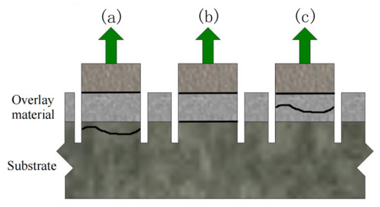
Figure 3.
UHPC–NC interfacial bond tensile test [29]: (a) failure in the substrate; (b) failure at the bond line; (c) failure in the overlay material.
Although the core pull-off test can overcome the shortcomings of the eccentric load of the direct tensile test, several factors affect its test results. Compared with the direct tensile test, the pull-off test damages the structure of the samples, which makes it difficult to achieve an ideal model of interface damage [28]. Hussein [29] designed a new tensile test device (Figure 4) that inhibits substrate failure. A steel sleeve was used as the constraint of the substrate. Interface failure occurred within the UHPC–high-strength-concrete (HSC) specimens with a moderately rough surface. Furthermore, a tensile stress of 5.01 MPa was obtained, which is 50% greater than the tensile strength of HSC at 56 days.
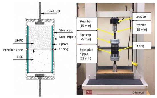
Figure 4.
Tensile test device designed by Hussein [29].
Valipour [34] designed a new testing method that reduces the interface transition zone damage caused by the drilling core pull-off test, improves the device, and reduces eccentric load. Figure 5 shows the UHPC designed as an inverted cone shape to induce interface failure. An ideal failure mode and good variation coefficients were obtained.
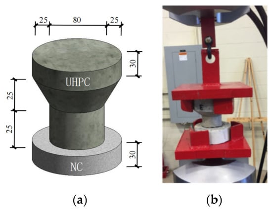
Figure 5.
Improved pull-off test designed by Valipour [34] (unit: mm): (a) specimen; (b) improved pull-off test set-up.
2.3. Split Test
Tayeh [35], Mansour [36], and Fan [37] proposed the split test to examine the UHPC–NC interface bonding strength. As an indirect test method, the split test can overcome the shortcomings of the pull-off test. A typical test specimen is divided into two shapes: cylindrical and cubic (Figure 6). During the test, the load is applied to the bonding surface using a pressure test machine, which is easy to use, resulting in a slight dispersion of the results. This approach is recommended as the standard test method in ASTM C496 [38]. Ren [39] investigated the effect of different interface treatment methods (i.e., interface agent and roughness) on the strength in the interface bonding zone using the split test. The test demonstrated that different interface treatment methods can result in different interface failure modes. Further, this approach can better evaluate the impact of different interface treatment techniques.
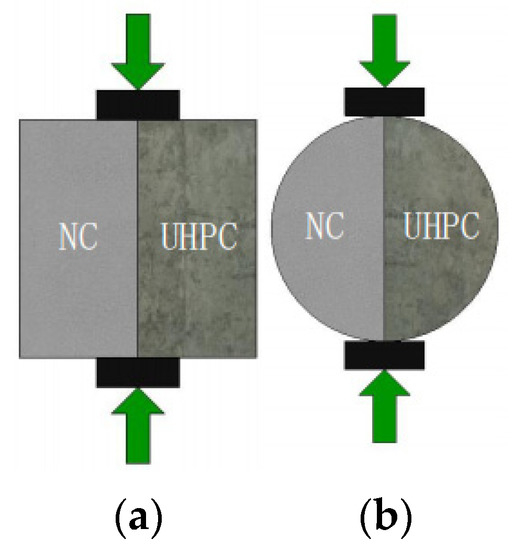
Figure 6.
Specimen for the indirect tensile split test method [39]: (a) cubic sample; (b) cylindrical sample.
Based on the split tests, Ren [39] achieved different interface failure modes. This test method can avoid damage to the structural interface transition area while evaluating the influence of different interface treatment methods on the bond strength. However, the elasticities of UHPC and NC affect the sample’s stress distribution, which has hardly been investigated. Thus, further studies are suggested for split tests.
2.4. Direct Shear Test
The direct shear test method takes advantages of the lower interface bonding strength between UHPC and NC rather than the shear strength in existing concrete substrates; however, this method is vulnerable to interface failure. The direct shear test includes single-sided, L-shaped, and double-sided shear [40], as shown in Figure 7. The single-sided direct shear test is simple to implement and allows easy load application (Figure 7a). However, the test load applied to the specimen can rarely pass the centroid section, causing eccentricity. In other words, the shear and bend stresses can affect the interface bonding zone, resulting in the concentration of stress within the interface bonding zone, which affects the reliability of the test results.
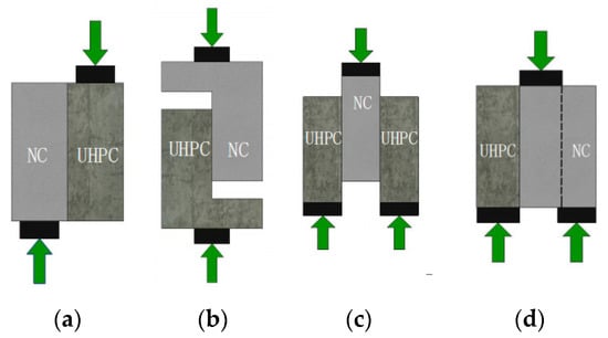
Figure 7.
Shear test: (a) single-sided direct shear test; (b) L-shaped direct shear; (c) bisurface 1; (d) bisurface 2.
Guan [41] and Javidmeh [42] designed the L-shaped shear test to overcome the shortcomings of the single-sided direct shear test (Figure 7b). This approach can reduce the influence of the eccentric load induced by the stress concentrations within the interfacial bonding zone. However, the stress concentration at the corner of the component is noted during the load application. An excessive stress concentration can cause specimen failure.
Mansour [36] and Momayez [43] designed two double-sided shearing tests. To resolve the above issues, the first double-sided shearing plane is located at the interface of the two materials (Figure 7c), and the second double-sided shear plane is located at the interface of the two materials within the existing concrete (Figure 7d). Momayez [43] investigated the effect of the interface roughness on the interface bonding strength using these two double-sided shearing tests. The interface bonding strength was revealed to be positively correlated to the roughness, and the dispersion of the test results was deduced.
Comparing the three straight shear tests, using the single-sided straight shear test, the load can be easily applied; however, the interface bonding area causes the concentration of stress and provides inaccurate test results. Meanwhile, the L-type shear test can reduce the concentration of stress within the interface bonding area; however, the specimen’s corner is prone to fracture caused by the stress concentration. The double-sided shear test reduces the concentration of stress, and the test results are more accurate.
2.5. Slant Shear Test
Slant shear tests are commonly used to determine the UHPC–NC interface bonding strength under the combined action of shear pressure [29]. Common specimen shapes include prisms and cylinders with a standard interface angle of 30° (Figure 8a). Based on the Moore–Coulomb theory, Figure 8b shows the relationships among the interface normal, shear, and maximum axial compressive stresses of an inclined shear specimen [29]. If the axial compressive stress at failure (σo) and the interfacial angle (α) are known, the normal (σn) and shear (τn) stresses at the interface can be calculated according to the diagram in Figure 8b.
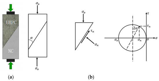
Figure 8.
Slant shear test [29]: (a) slant shear test; (b) slant shear stress analysis diagram.
Carbonell [30] investigated the effect of different interface angles (55°, 60°, and 70°) on the specimen failure modes through the slant shear test. It was revealed that interface failure occurred in specimens with interface angles of 70°, whereas substrate failure occurred in the remaining specimens. The specimen failure modes had different interface angles. As different specimen failure modes are obtained with different interface angles, selecting an appropriate interface angle can accurately reflect the actual interface bonding strength [44]. Austin [45] discovered that interface angle and roughness considerably affect the slant shear test results. Moreover, an analytical method was developed for predicting the critical angle while considering the influence of the internal friction angle using numerous slant shear tests. The compressive stress required for the interface failure was minimal when the specimen was at a critical angle.
Austin [45] experimentally validated the aforementioned analysis method and determined the relationship between the ratio of the failure stress to the pure shear strength and the interface angle. The smooth, moderately rough, and extremely rough interfaces had critical angles of 27°, 23°, and 19°, respectively. If the interface angle exceeds the critical angle, the interfacial failure stress ratio, defined as the ratio of the failure stress to the pure shear strength, rapidly increases. Thus, a small angle between the inclined planes should be used to promote the interfacial failure of specimens with rough surfaces. However, if the elastic modulus and Poisson’s ratio of the two materials do not match, further slant shear tests with the UHPC–NC samples are required.
2.6. Bending Test
The interfacial bending test method is commonly used to measure the bonding strength and obtain the UHPC–NC interface bonding strength under bent conditions. The three- and four-point bending methods are the most commonly used interfacial bending methods. Figure 9 shows the loading method and specimen shape [46]. The interface bonding surface of Figure 9a–c is a horizontal plane, whereas that of Figure 9d is a vertical plane. In this test, the machine load is applied at the midpoint or at three points on the upper surface of the test specimen. Assuming that the test specimen meets the horizontal section, the bonding performance of the interface between the two materials is evaluated using the following crucial criterion: the interface does not slip during load application. The simplicity of the test procedure and the ability to observe the crack resistance of the component are two advantages of the bending test. Conversely, its disadvantage is the low specimen usage rate.
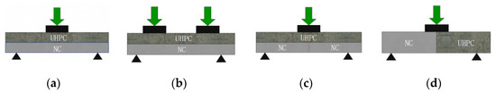
Figure 9.
Bending test: (a) bending prism test 1; (b) bending prism test 2 at the horizontal interfacial plane; (c) bending prism test 3 at the vertical interfacial plane; (d) bending prism test 4 at the vertical interfacial plane.
3. Theories of the Interfacial Bonding Shear Strength
The formulas for calculating the interface bonding shear strength of new and old NC (NC–NC) are derived based on shear friction theory or test data derivation. However, the Chinese standard “Concrete Structure Design Code” (GB50010-2010) states that the interface shear strength of a composite section [41,47,48] should not exceed 0.4 N/mm2 to conform to the structural provisions.
Researchers have derived multiple theoretical formulas for the calculation of UHPC–NC interface shear strength. Zhou [26] and Wang [49] conducted an experimental study on the effect of a keyway structure on the UHPC–NC interface bonding shear strength and discovered conservative calculations based on Chinese norms. Tayeh [32] investigated the effect of the interfacial reinforcement of bars on the interface bonding shear strength of UHPC–HSC using shear friction theory (Figure 10). It was found that the interfacial shear-reinforcing bars play an important role in load transfer. The shear-bearing capacity of the specimen was higher than the values promoted by the American Association of State Highway and Transportation Officials Load Resistance Factor Design [48] and 2010 Comité Euro-International du Beton International Federation for Structural Concrete Code [50,51]. Hence, the standard calculated value of the composite members is conservative and dependent on the interface shear strength of the NC composite members rather than the mechanical properties of the UHPC. Therefore, the UHPC–NC interface bonding shear strength calculated using the codes is conservative.
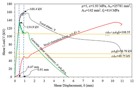
Figure 10.
Components of the shear friction behavior [12].
Considering the aforementioned problems, the UHPC–NC interface shear strength was fitted based on the test results. The deduced formulas for the corresponding interface bonding bearing capacity are listed in Table 1. Wang [49] developed a shear calculation formula for the UHPC–NC interface considering the keyway effect based on Eurocode 2 [52]. The shear formula of the interface bonding strength of UHPC–NC with a changing interface roughness was derived by Feng [27]. Gopal [53], Yang [54], and Pan [55] investigated the keyway effect on the shear capacity of the UHPC–NC interface and deduced the shear formula considering the polygon-key bolt force based on shear friction theory. Li [56] developed a shear formula based on the strengthening effect of steel fiber on the interface bonding shear strength.

Table 1.
UHPC–NC interface shear strength calculation formulas.
4. Factors Affecting the UHPC–NC Interface Adhesion
Previous studies have shown that interface roughness, fiber content, interface agent, interface water content, existing concrete strength, cementitious materials, maintenance system, corrosive substances (such as chloride ions), and the freeze–thaw cycle considerably affect the interface bonding performance of UHPC–NC [29,41,57].
4.1. Interface Roughness
Interface roughness is an important factor affecting the UHPC–NC interfacial adhesion [28,57,58]. The concrete surface of UHPC–NC composite members must be treated to improve the original interface roughness. Current common treatment methods include high-pressure water jet roughening, grooving, brushing, roughening, drilling, sandblasting, and planting reinforcement [28]. Some interface treatment methods are shown in Figure 11.
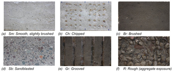
Figure 11.
Different surface treatments for NC substrates [9].
The interface roughness is affected by different interface treatment methods. The relationship between the roughness and bonding strength is determined by different tests. Ren [39] demonstrated that the interface bonding strength between UHPC and NC increases with the increasing surface roughness of the NC substrate. The highest interface bonding strength was obtained at a surface roughness depth of 4 mm. Water spraying as an interface treatment can considerably improve the shear strength of the construction joints [59].
Hussein [29] investigated the UHPC–HSC structural interface bonding strength under different roughness conditions using a direct tensile test. The bonding strength at the UHPC–HSC structure interface was reported to increase with an increasing roughness. Moreover, the specimen developed cracks in the HSC layer, and the interface bonding strength was higher than those obtained by Harris [60] and Jung [61] using pull-off tests. Harris [60] performed slant shear and split tensile tests to examine the effect of different roughness values on the UHPC–NC structure interface bonding strength. In the slant shear test, the bonding strength of the specimens with interfaces with low and high roughness values increased by 26% and 56%, respectively, compared to those of the smooth interface components. Both shear and slant shear tests can provide better evaluation of the effect of interface roughness; however, the sensitivity of the core pull-off and composite beam tests was lower than that of the former. Carbonell [30] and Tayeh [35] performed the UHPC–NC core pull-off and bending tests. Regardless of the treatment of the NC substrate (untreated or sandblasted), the specimen substrate was always damaged. Wang [59] used five interface treatment methods on the specimen. The high-pressure water jet was found to be the most effective method for improving the interface bonding strength. Zhang [28] discovered that the average failure strength of the smooth, drilled, grooved, and planted bar interfaces decreased by 35.20%, 25.90%, 9.40%, and 6.50%, respectively, compared to that of the rough interface. Yang [62] investigated the effect of different interface planting bar rates on the shear strength within the interface bonding zone using double-sided shear tests. Specimens with 0.09%, 0.19%, and 0.29% planting bar rates can achieve interface bonding shear strengths that are 1.54, 1.98, and 2.66 times that of specimens without planting bars, respectively. Feng [63] investigated the effects of the trapezoidal, rectangular, and inverted trapezoidal polygon keys on the interface bonding strength of a specimen using direct shear tests. The failure mode, initial crack and peak strength, peak shear slip, ductility coefficient, and peak-load-to-initial-crack-load ratio of the three polygon keys were nearly identical. Among these, the trapezoidal polygon key with an included angle of not more than 113° should be selected to facilitate construction.
Alhallaq [64] tested specimens to determine the interface bonding strength relationship between the roughness coefficient (Ra) and UHPC–NC. The tensile and shear strengths increased as the interface roughness coefficient increased. Increasing the roughness is not the preferred treatment method when the interface is under tension [30,35,62,63]. Other interface treatment methods can achieve good results. In detail, increasing the interface roughness can improve the interface bonding performance; however, excessive interface treatment can damage the substrate and reduce the interface bonding performance. Using slant shear, split, and direct tensile tests, Zhang [28] investigated the effect of NC surface grooving, punching, and other treatments on the interface bonding performance. Figure 12 shows that the bonding strength of the UHPC–NC interface decreases with an excessively high interface roughness. The analysis revealed that excessive interface treatment causes microcracks on the NC surface. Moreover, although pneumatic hammer chisel technology can improve the NC interface roughness, high-impact energy forms microcracks on the NC substrate, causing stress concentration [65].
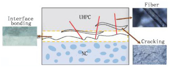
Figure 12.
Principle of the fiber-reinforced interface properties [39].
4.2. Fiber Addition
The interface bonding properties of UHPC–NC can be improved by adding different types of organic or inorganic fibers [65,66]. Figure 12 shows the theoretical and analytical results of the fiber-reinforced interface characteristics. Fibers can reduce UHPC shrinkage and stress caused by poor shrinkage. Moreover, the risk of interface cracking caused by material shrinkage is effectively reduced with a thin reinforcement surface. Moreover, under an applied load, the bridged effect between fibers can effectively inhibit microcrack development in UHPC, redistribute the stress around the main crack, increase the residual stress after cracking, and change the force transfer and failure modes of the bonding surface. Subsequently, the fibers distributed in the disordered direction can improve the UHPC interface roughness, and those at the bonding surface can extend into the gap of the NC interface, improving the mechanical interlock force between UHPC and NC. Masse [67], Xie [68], Shuo [69] and Ren [39] discovered the effect of interface factors, such as fiber distribution direction and dosage, on the interface bonding performance. Huang [46] conducted the interface bonding test of UHPC–NC using the split tensile test method. It was discovered that two specimens with 1.5 vol.% fiber experienced split failure at the NSC layer, whereas the remaining specimens underwent bond failure at the ultrahigh-performance fiber-reinforced concrete (UHPFRC)–NSC interface. The NSC layer demonstrated a lower failure load than that of the UHPFRC–NSC/HSC interface.
Jang [70] compared the interface bonding shear strength of UHPC–UHPC and UHPC–NC specimens through an L-shaped shear test, whereby the specimens were mixed with steel fibers. UHPC–UHPC was noted to have higher ductility and bearing capacity than that of UHPC–NC, as shown by the load–displacement curve in Figure 13. Pan [55] discovered that a steel fiber dosage of 1–2% can considerably improve the shear-bearing capacity of UHPC–NC. In [65], the effect of 2, 3, and 4 vol.% steel fiber dosages on the interface bonding strength of UHPC–NC was tested. The tensile strength within the interface bonding zone clearly increased with an increasing volume content of steel fibers. At 4 vol.% fiber, the interface split strength reached 92% of the overall split strength of cast NC. Through a flexural test, It is discovered that the split tensile strength within the interface bonding zone increases with the steel fiber volume dosage. The tensile strength of the interface bonding split increased by 80% from that of the specimen without steel fiber under a 2.0% steel fiber volume dosage [71,72].
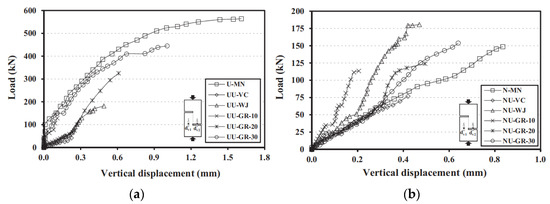
Figure 13.
Load–displacement curves of two test blocks [59]: (a) UHPC–UHPC; (b) UHPC–NC.
4.3. Interfacial Adhesive Agents
Interfacial adhesive agents are broadly classified into cement-based composite and polymer materials [29]. The hydrating products of cement-based composites fill the pores at the interface, forming a compact transitional layer and improving the mechanical properties of the layer interface. Polymer penetration effectively inhibits crack expansion and increases the bonding force of the interface layer by permeating through the NC microcracks [28,64,73].
In [65], the effects of the absence of an interfacial adhesive agent and the use of cement paste, silica ash paste, cement swelling slurry, and butadiene emulsion on the interfacial bonding strength of UHPC–NC was compared using split tests. Except for butadiene emulsion, using interfacial agents improved the interfacial bonding strength. Typically, an interface agent is required for precast UHPC–NC composite components. Wu [57] used structural adhesives and grouting materials of cement as the interface agents of prefabricated UHPC–NC components. The superior effect of the structural adhesives over cement-based grouting materials was reported. Therefore, structural adhesives are good interfacial agents.
The interfacial agent ratio influences the effect of interfacial bonding. Zheng [74] conducted an experimental study and reported the different degrees of improvement of the interfacial bonding strength with the incorporation of different interfacial agents. The bonding split tensile strengths of UHPC–NC gradually increased as the interfacial agent incorporation ratio increased. Ganesh [75] investigated the effect of the interfacial agent on the interfacial bonding strength of cast UHPC–NC and precast UHPC–NC specimens. During the slant shear, four-point bend, and split tensile tests, the interfacial bonding strength of the precast specimens using epoxy resin increased by 12.20%, 26.10%, and 60%, respectively, compared with the cast samples (Figure 14).

Figure 14.
Effects of the epoxy-based adhesive agent on the interfacial bonding strength [26].
Wang [76] compared the interface bonding strengths of precast and cast UHPC–NC components with multiple interface agents using pull-off tests. Phenylene butadiene slurry was demonstrated as the best interfacial agent, followed by modified fly ash, silica fume paste, expanded cement paste, and cement paste. Moreover, the structural adhesives considerably improved the interfacial shear bonding strength compared to cement grouting materials [74]. Under an established shear connector, the direct shear strength of the specimen bonded by a grouting material was lower than that required by the regulations issued by the American Concrete Institute (ACI). However, the direct shear strength of the specimen bonded by a structural adhesive can satisfy the ACI requirements.
Through drilling core and bending tests, Tayeh [35] discovered the specimen failure at the NC substrate with UHPC as the interfacial agent. Valikhani [40] designed two UHPC samples with different interfacial roughness values to investigate its effect as the interfacial agent between UHPC and NC. Compared to the specimens without interfacial agents (S and R), the interface bonding strength of the specimens with interfacial agents (SB and RB) decreased by 14% and 50%, respectively (Figure 15). Thus, the enhancement effect using UHPC as the material interfacial agent with different interface roughness conditions should be investigated.
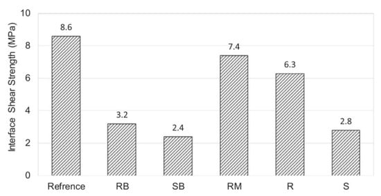
Figure 15.
Average bond strength for each group of tests.
4.4. Interfacial Water Content
The effect of the interfacial water content on the bonding properties of the UHPC–NC interface bonding zone primarily occurs when water exists on the NC surface. This slows down water migration in UHPC and promotes the production of hydration products and the reduction of porosity in the interfacial transition zone [28,77,78,79]. Microscopic tests have been performed to investigate the effects of different interfacial water contents on the hydration products and porosity of the interfacial transition area [80,81]. As shown in Figure 16, Group SSD (interfacial pre-wetting) had a higher proportion of hydration products, which improved the compactness of the interfacial transition area.
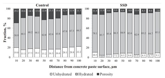
Figure 16.
Overall porosity and hydrated and unhydrated distributions on the grout side of the interface for the control and SSD specimens [80].
Zhang [28], Hussein [29], and Bentz [80] demonstrated that a pre-wetted NC surface affects the interface bonding properties of new and old materials, and a wetted NC substrate can improve the interface bonding strength of composite members. The bonding property of the UHPC–NC interface is considerably affected by the wetting degree of the NC base and is positively correlated with the interface shear strength. The references [81,82,83,84] conducted an axial tensile test on specimens after treating them with SSD, ASW, and ASD. It was found that increasing the wetting degree of the NC substrate under natural curing conditions improved the crack load and load capacity of the UHPC–NC specimens under the axial tensile test. Meanwhile, Farzad [82] and Bentz [80] believed that interfacial pre-wetting treatment does not improve the bonding properties of the UHPC–NC interface because the water from the UHPC flows to the NC substrate during the slant shear test, increasing the water-to-binder ratio. According to Beushausen [85], SSD has a negative impact because of the increase in the porosity and water–cement ratio of the interface, which are related to the fluidity of the UHPC and material properties of NC.
Bentz [80] investigated the effect of different interfacial moisture contents on the interface bonding strength between UHPC–NC and NC–NC. Under SSD conditions, the interface is conducive to the interface bonding strength improvement. Semendary [83] discovered that wetting surface treatment effectively inhibits interfacial failure, reduces the randomness of the failure mode, and improves the overall mechanical properties of specimens compared to the drying treatment of the NC surface. Figure 17 illustrates the influence of the interfacial moisture content on the tensile bonding strength.The interfacial bonding strength of UHPC–NC increased by 34%, similar to that obtained by Huo [84].
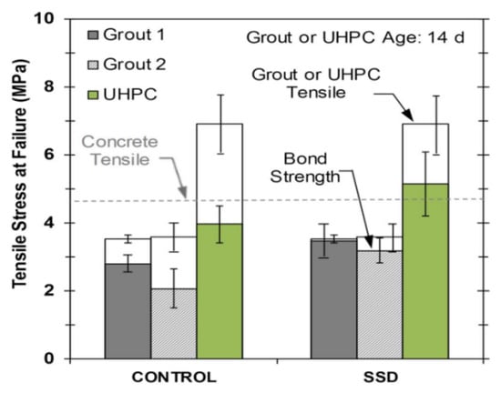
Figure 17.
Effect of the substrate’s moisture condition on the tensile bonding strength [17].
Several researchers noted that pre-wetting has no considerable effect on the interfacial bonding properties. By performing three-point bending and single-plane shear tests, Farzad [82] demonstrated that the shear strength of the interfacial bonding of UHPC–NC on a wet surface is higher than that on a dry surface. However, the slant shear test results were contradictory, consistent with the conclusions of Bentz [80]. Moreover, Beushausen [85] investigated the effect of different water contents on the interfacial bonding characteristics and microstructures of three NC samples (i.e., different porosities and water absorption characteristics). Wetting the NC surface did not improve the interface bonding strength but increased the water–cement ratio and porosity of the interfacial transitional zone. Therefore, the interfacial bonding characteristics are affected by the interfacial moisture content, material properties of NC, and fluidity of UHPC.
4.5. Existing Concrete Strength
Existing concrete strength is an important factor of the interface bonding strength of old and new concrete [28,72,86]. Feng [27] investigated the effects of NC with different strength values on the interface bonding strength of UHPC–NC and NC–NC through split and slant shear tests (Figure 18). The test result revealed that the interface bonding strength of UHPC–NC increases with the existing concrete strength. The improvement in the interface bonding strength is better than that of NC-reinforced materials, which is consistent with the conclusions drawn by Wu [57]. Zhang [28] and Carbonell [30] discovered that increasing the existing concrete strength can improve the strengthening effect of the interfacial agent, demonstrating that the existing concrete strength is an essential factor of the interfacial bonding zone.
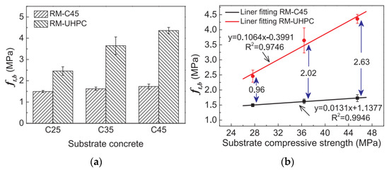
Figure 18.
Effects of the NC strength on the interfacial bonding strength [27]: (a) SC; (b) ratio of the press in the base.
4.6. Binding Material
The cementitious materials within the UHPC raw materials are silica fume and fly ash, which improve the microstructure of the interface bonding strength. Haber [20], Tayeh [35], and Shen [73] examined the transition region of the UHPC–NC interface by scanning electron microscopy (Figure 19). The UHPC–NC interface has a dense and uniform transition region. The chemical reaction between reactive silica (SiO2) in silica ash and calcium hydroxide (Ca(OH)2) in the NC substrate formed a C–S–H hydration product, which filled the gaps at the interface and improved the compactness of the interfacial transition area.
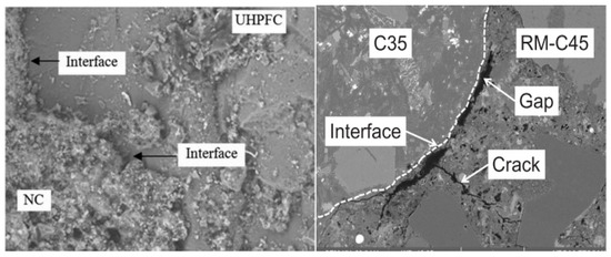
Figure 19.
SEM of the UHPC–NC interfacial transition zone [35].
The physical action of silica fume in concrete refined the void system of the cement paste, particularly the transition zone. The microstructure of the interface zone can be further improved with time because of a secondary reaction between the existing Ca(OH)2 and pozzolana, resulting in a denser interface zone with better durability. The noticeable improvement in the microstructure facilitated a considerable increase in the intermolecular force and mechanical interlocking, increasing the bond strength (Figure 19).
4.7. Curing
The curing protocol affects the UHPC shrinkage and interface bonding performance and adds stress to the interface [87]. Huo [84] compared the cracking resistance and interfacial bonding performance of UHPC–NC flexural specimens under steam curing at 60 °C and natural curing. The results showed that steam curing could improve the bonding performance of the UHPC–NC interface. In particular, the interfacial cracking resistance of the specimens cured by steam at 60 °C for 72 h was considerably stronger than that of the interface naturally cured for 28 d. Feng [88] and Wu [89] compared the influence of different curing systems on the interface shear bonding strength of UHPC–NC and found that the interface bonding strength of the specimens under normal-temperature curing is higher than that under thermal curing. Zhang [28] conducted experimental studies under different curing conditions and showed no considerable difference in the interface bonding strength. However, the interface bonding strength of the specimens obtained by steam curing at 90 °C was lower than that of the specimen obtained by curing at 60 °C and normal-temperature steam curing. This result can be attributed to the rapid shrinkage of UHPC because of high temperatures, which caused an uneven interface stress distribution and resulted in microcracks in the interface, limiting the development of the interface bonding strength. Therefore, a suitable curing system should be identified to minimize the impact on the interface bonding performance.
4.8. Chloride Ions and Other Corrosive Substances
The composite member interface is porous and prone to seepage channel formation. Consequently, harmful chloride ions and other erosive substances enter the UHPC–NC interface, causing the degradation of the hydration products and decreased interface bonding strength [90,91]. Consequently, the ability of the UHPC–NC interface to prevent chloride erosion is important. Li [92] and Gao [93] conducted tests on standard impermeable specimens using the seepage height method (Figure 20). Various factors, such as interfacial agent and fiber addition, were found to considerably improve the interfacial impermeability of old and new concrete and the interface bonding strength of UHPC–NC.
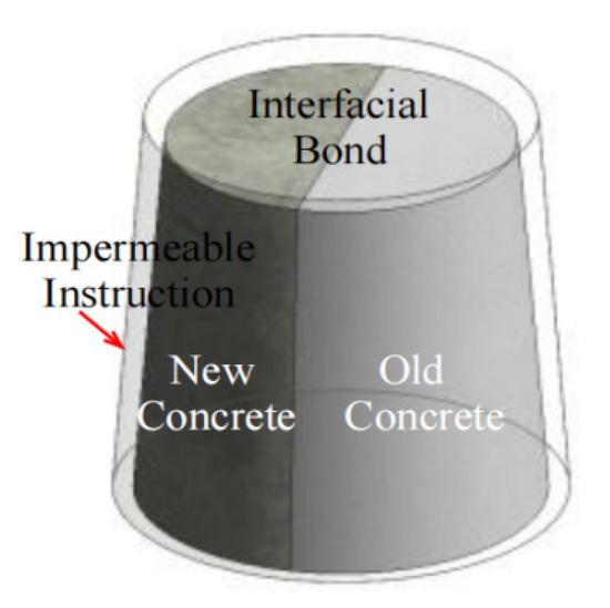
Figure 20.
Interface permeability test.
4.9. Freeze–Thaw Cycles
UHPC is almost unaffected by the freeze–thaw cycle in UHPC–NC specimens; however, its interface transition zone has high porosity and multiple tiny cracks, making it the weakest part of the combined member. In [64,72,78,94], the effect of the freeze–thaw cycles on the interface bonding strength of UHPC–NC was investigated. The interface bonding strength decreased as the number of freeze–thaw cycles increased. Yu [95] investigated the effect of different factors on the interface bonding performance of the specimens under freeze–thaw cycles, reporting that the steel fiber content and interface roughness considerably affected the interface bonding split strength, whereas the casting direction exerted only a minor effect. Feng [27] investigated the effect of the freeze–thaw cycles on the interface bonding strength of UHPC–NC and NC–NC using the constraint ring method. The interface bonding strength of UHPC–NC considerably decreased to less than that of the NC–NC. Furthermore, Lee [96] conducted 0, 300, 600, and 1000 freeze–thaw cycles on combined specimens of NC–NC, NC high-strength mortar (HSM), UHPC–NC, and UHPC–UHPC to compare and analyze the interface bonding strengths through slant shear tests. As shown in Figure 21, the interface bonding strength decreases to different degrees. Moreover, UHPC–NC has higher bonding strength and freeze–thaw resistance than NC–NC.
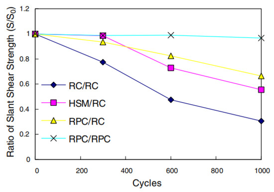
Figure 21.
Ratio of the slant shear strength under freeze–thaw cycles [96].
5. Conclusions and Prospects
5.1. Conclusions
(1) Herein, the test methods for measuring strength in the UHPC–NC interface bonding zone were reviewed. For external load applications, the direct tensile test can cause eccentric force, making it unsuitable for measuring adhesion, because the interfacial transition is easily damaged. The split test is easily affected by additional bending deformation when the direct shear test is performed. Moreover, the slant shear test is easily affected by the interface angle and roughness. Bending tests have a low usage rate and small load bonding area, which can easily cause stress concentration. Therefore, different test methods considerably affect the measurement of the interface bonding strength of composite structures.
(2) A considerable difference between the UHPC–NC interface bonding shear strength test and formula values calculated from the relevant codes in various countries was reported. In particular, the conservative calculated values were obtained from specifications because they only focus on the NC-reinforced interface and do not fully consider the influence of the mechanical properties of UHPC.
(3) The main factors affecting the interface bonding strength are interface roughness, fiber type and content, interfacial agent type, interfacial moisture content, existing concrete strength, cementified materials, curing conditions, chloride ions and other erosive substances, and the freeze–thaw cycle.
(4) Among the multiple factors affecting the interface bonding strength, the interface bonding performance can be considerably improved by appropriately increasing the interface roughness. However, excessive interface treatment can damage the substrate and reduce the interface bonding performance. Fiber addition effectively improves the interface bonding performance of UHPC–NC by reducing UHPC shrinkage and improving the mode of interfacial load transfer. Although most interface agents can improve the interfacial bond strength, the effect of using UHPC as an interface agent is controversial and needs further study. The bonding properties of the UHPC–NC interface are affected by the water content of the interface. The interface transition area density and bonding strength improved under wet saturation and SSD condition.
(5) The presence of cementitious materials, such as silica fume and fly ash, in UHPC can improve the interface microstructure, which is suitable for increasing the interface bonding strength. The strengthening effect of the interfacial agent can be improved by increasing the existing concrete strength. As the curing system affects the UHPC interface bonding strength, selecting a suitable curing system is essential. The interface bonding strength decreases when harmful chloride ions and other erosive substances enter the UHPC–NC interface. An interfacial agent and fiber can effectively improve the impermeability of the interface between old and new concrete and the bonding strength of the UHPC–NC interface.
5.2. Prospects
(1) Various strength test methods for the UHPC–NC interface bonding zone are prone to causing the failure of the existing concrete substrate, resulting in the difficulty in measuring the interface bonding strength and achieving inaccurate results. The test method used to induce the specimen interface failure should be improved to obtain a more accurate interface bonding strength.
(2) The relevant codes of various countries do not completely consider the influence of the mechanical properties of materials in the calculation formula of the UHPC–NC interface bonding shear strength. Furthermore, the types of interface treatment methods considered are limited, and their impacts on the interface bonding zone and shear strength were not considered. Consequently, the calculation formula should consider the influence of the mechanical properties of materials, interface treatment methods, and other factors.
(3) The lack of relevant research on the UHPC–NC interface in the context of the interface bonding performance, UHPC water–binder ratio, substrate material water absorption, and cast direction of the interfacial water content prompts the need for additional investigations of the interface bonding performance of UHPC–NC under various factors.
(4) The lack of relevant research on the UHPC–NC interface in the context of the freeze–thaw cycle, chloride penetration, dry–wet cycle, and other factors has led to a limited understanding of UHPC–NC under harsh environmental conditions. Thus, research on these topics must be expanded.
Author Contributions
Conceptualization, L.X., J.S. and Y.W.; methodology, Y.L., Y.Y. and J.S.; validation, L.X. and Y.W.; investigation, L.X., Y.W. and Y.Y.; resources, J.S. and Y.L.; data curation, Y.W. and Y.Y.; writing—original draft preparation, L.X. and Y.W.; writing—review and editing, Y.W., Y.L. and J.S.; visualization, L.X.; supervision, Y.W., Y.L. and Y.Y.; project administration, Y.W. and J.S. All authors have read and agreed to the published version of the manuscript.
Funding
This research was funded by the Sichuan Provincial Natural Science Foundation Project; Project Grant No: 2022NSFSC1174.
Institutional Review Board Statement
Not applicable.
Informed Consent Statement
Not applicable.
Data Availability Statement
Not applicable.
Conflicts of Interest
The authors declare no conflict of interest.
References
- Bao, C.C.; Tao, J.; Huang, Q.W. Review of Research on Ultra-High Performance Concrete. J. Archi. Civ. Eng. 2014, 3, 1–24. [Google Scholar]
- Wang, D.H.; Shi, C.J.; Wu, L.M. Research and Applications of Ultra-High Performance Concrete (UHPC) in China. Bull. Chin. Ceram. Soc. 2016, 35, 141–149. [Google Scholar]
- Huang, W. Effect of Supplementary Cementitious Material on the Hydration and Microstructural Development of Ultra-High Performance Concrete. Ph.D. Thesis, Southeast University, Nanjing, China, 2017. [Google Scholar]
- Baqersad, M.; Sayyafi, E.A.; Bak, H.M. State of the Art: Mechanical Properties of Ultra-High Performance Concrete. Civ. Eng. J. 2017, 33, 190–198. [Google Scholar] [CrossRef]
- Saucier, F.; Bastien, J.; Pigeon, M. A Combined Shear-Compression Device to Measure Concrete-to-Concrete Bonding. Exp. Technol. 2010, 15, 50–55. [Google Scholar] [CrossRef]
- Mansouri, I.; Shahheidari, F.S.; Hashemi, S.M.A. Investigation of steel fiber effects on concrete abrasion resistance. Adv. Concr. Constr. 2020, 9, 367–374. [Google Scholar]
- Farzampour, A. Temperature and humidity effects on behavior of grouts. Adv. Concr. Constr. 2017, 5, 659–669. [Google Scholar]
- Chalangaran, N.; Farzampour, A.; Paslar, N. Nano Silica and Metakaolin Effects on the Behavior of Concrete Containing Rubber Crumbs. J. Civ. Eng. 2020, 1, 264–274. [Google Scholar] [CrossRef]
- Hu, Y. The Axial Compressive Performance Study of Reactive Powder Concrete Precast Tube Concrete Composite Columns. Master’s Thesis, Hunan University, Changsha, China, 2015. [Google Scholar]
- Li, V.C. High Performance Fiber Reinforced Cementitious Composites as Durable Material for Concrete Structure Repair. J. Int. Rest. 2004, 10, 163–180. [Google Scholar]
- Sun, H.X.; Zhou, J.T.; Xu, A.Q. Research Progress of UHPC Reinforcement Technology in Bridge Engineering. Concrete 2020, 1, 136–143. [Google Scholar]
- Liu, Z. Reactive Powder Concrete Technology and Its Application in Anti-Collision Wall. Master’s Thesis, Shenyang Jianzhu University, Shenyang, China, 2019. [Google Scholar]
- Luo, X.B. Experimental Study on Concrete-filled RPC Tube Under Axial Compressive Loading. Master’s Thesis, Hunan University, Changsha, China, 2017. [Google Scholar]
- Wen, S. Numerical Study on Seismic Performance of a Novel Type of High-strength Reinforced UHPC-NC Composite Column. Master’s Thesis, East China Jiaotong University, Nanchang, China, 2020. [Google Scholar]
- Teng, T.; Yuan, S.Q.; Wang, J.Q.; Liu, Z. The Role of Bond Strength in Structural Behaviors of UHPC-NC Composite Beams: Experimental Investigation and Finite Element Modeling. Compos. Struct. 2021, 52, 255–269. [Google Scholar] [CrossRef]
- Liu, C.; Sun, Q.X.; Zou, Y.G. Experimental Study on Bending Performance of Ultra-high Performance Concrete-Normal Concrete Composite Simply Supported Beam. Chin. Tongji Univ. 2020, 48, 664–672, 701. [Google Scholar]
- Semendary, A.A.; Hamid, W.K.; Steinberg, E.P. Shear Friction Performance between High Strength Concrete (HSC) and Ultra High Performance Concrete (UHPC) for bridge connection applications. Eng. Struct. 2020, 205, 110122.1–110122.14. [Google Scholar] [CrossRef]
- Lee, H.S.; Jang, H.O.; Cho, K.H. Evaluation of Bonding Shear Performance of Ultra-High Performance Concrete with Increase in Delay in Formation of Cold Joints. Materials 2016, 9, 362. [Google Scholar] [CrossRef] [PubMed]
- Huo, S.Y. The Research on Shaft Pull Performance of Assembled NC Components with UHPC Wet Joints. Master’s Thesis, Hunan University, Changsha, China, 2017. [Google Scholar]
- Haber, Z.B.; Munoz, J.F.; Igor, D. Bond Characterization of UHPC Overlays for Concrete Bridge Decks: Laboratory and Field Testing. Constr. Build. Mater. 2018, 190, 1056–1068. [Google Scholar] [CrossRef]
- Gu, C.P.; Ye, G.; Sun, W. Ultra High Performance Concrete-Properties, Applications and Perspectives. Sci. Chin. Technol. Sci. 2015, 58, 587–599. [Google Scholar] [CrossRef]
- Caluk, N.; Mantawy, I.; Azizinamini, A. Durable Bridge Columns Using Stay in Place UHPC Shells for Accelerated Bridge Construction. Infrastructures 2019, 4, 25. [Google Scholar] [CrossRef]
- Fu, X.; Song, R.X.; Wang, W.P. Detection of Bond Strength of Patching Concrete with the Core-drilling and Pulling-stripping Method. Constr. Technol. 2005, 34, 72–73. [Google Scholar]
- Mohammed, K.; Mohammed, A.M. Interfacial bond behavior between ultra high performance concrete and normal concrete substrates. Constr. Build. Mater. 2022, 320, 126229. [Google Scholar]
- Daneshvar, D.; Behnood, A.; Robisson, A. Interfacial bond in concrete-to-concrete composites: A review. Constr. Build. Mater. 2022, 359, 129195. [Google Scholar] [CrossRef]
- Zhou, J.T.; Zhou, L.; Yang, J. Summarization on Bonding Behaviors of Ultra-high Performance Concrete and Normal Concrete. J. Chin. Jiangsu Univ. 2020, 41, 373–381. [Google Scholar]
- Feng, Z.; Li, C.X.; Li, H.C. Interfacial Bond Performance of Ultra-high Performance Concrete Wet Joints. J. Chin. Ceram. Soc. 2021, 49, 2393–2404. [Google Scholar]
- Zhang, Y.; Zhu, P.; Liao, Z. Interfacial Bond Properties between Normal Strength Concrete Substrate and Ultra-high Performance Concrete as A Repair Material. J. Constr. Build. Mater. 2020, 235, 1174–1191. [Google Scholar] [CrossRef]
- Hussein, H.H.; Walsh, K.K.; Sargan, D.S.M. Interfacial Properties of Ultrahigh-Performance Concrete and High-Strength Concrete Bridge Connections. J. Mater. Civ. Eng. 2016, 28, 04015208.1–04015208.10. [Google Scholar] [CrossRef]
- Carbonell Muñoz, M.A.; Harris, D.K.; Ahlborn, T.M. Bond Performance between Ultra-high Performance Concrete and Normal-Strength Concrete. J. Mater. Civ. Eng. 2014, 26, 04014031.10–04014031.22. [Google Scholar] [CrossRef]
- Sprinkel, M.M.; Ozyildirim, C. Evaluation of High Perforomance Concrete Overlays Placed on Route 60 Over Lynnhaven Inlet in Virginia. J. Concr. Overlays 1999. [Google Scholar]
- Tayeh, B.A.; Abu Bakar, B.H.; Megat Johari, M.A. Characterization of the Interfacial 15 Bond between old concrete substrate and ultra high performance fiber concrete repair 16 composite. Mater. Struct. 2013, 46, 743–753. [Google Scholar] [CrossRef]
- Bonaldo, E.; Barros, J.A.; Lourenço, P.B. Bond Characterization between Concrete Substrate and Repairing SFRC Using Pull-Off Testing. Int. J. Adhes. Adhes. 2005, 25, 463–474. [Google Scholar] [CrossRef]
- Valipour, M.; Khayat, K.H. Debonding Test Method to Evaluate Bond Strength between UHPC and Concrete Substrate. Mater. Struct. 2020, 53, 1–10. [Google Scholar] [CrossRef]
- Tayeh, B.A.; Bakar, B.A.; Johari, M.M. Microstructural Analysis of the Adhesion Mechanism between Old Concrete Substrate and UHPFC. J. Adhes. Sci. Technol. 2014, 28, 1846–1864. [Google Scholar] [CrossRef]
- Mansour, W.; Fayed, S. Effect of Interfacial Surface Preparation Technique on Bond Characteristics of Both NSC-UHPFRC and NSC-NSC Composites. Structures 2021, 29, 147–166. [Google Scholar] [CrossRef]
- Fan, J.; Wu, L.; Zhang, B. Influence of Old Concrete Age, Interface Roughness and Freeze-Thawing Attack on New-to-Old Concrete Structure. Materials 2021, 14, 1057. [Google Scholar] [CrossRef] [PubMed]
- ASTM. Standard Test Method for Splitting Tensile Strength of Cylindrical Concrete Specimens. In Annual Book of ASTM, Standards; ASTM: West Conshohocken, PA, USA, 1996. [Google Scholar]
- Ren, L.; Fang, X.; Wang, K. Research Progress on Interface Bond Behavior between Ultra High Performance Concrete and Cement-Based Mater. Bull. Chin. Ceram. Soc. 2019, 38, 2087–2094. [Google Scholar]
- Valikhnai, A.; Jahromi, A.J.; Mantawy, I.M. Experimental Evaluation of Concrete-to-UHPC Bond Strength with Correlation to Surface Roughness for Repair Application. Constr. Build. Mater. 2019, 238, 117753–117765. [Google Scholar] [CrossRef]
- Guan, D.; Liu, J.; Jiang, C. Shear Behaviour of the UHPC-NSC Interface with Castellated Keys: Effects of Castellated Key Dimension and Dowel Rebar. Structures 2021, 31, 172–181. [Google Scholar] [CrossRef]
- Javidmehr, S.; Empelmann, M. Shear Bond between Ultra-High Performance Fibre Reinforced Concrete Overlays and Normal Strength Concrete Substrates. Sustainability 2021, 13, 8229. [Google Scholar] [CrossRef]
- Momayez, A.; Ramezanianpour, A.A.; Rajaie, H. Bi-Surface Shear Test for Evaluating Bond between Existing and New Concrete. ACI Mater. 2004, 101, 99–106. [Google Scholar]
- Yuan, S.; Liu, Z.; Tong, T. Investigation of Over-Nonlocal Damage and Interface Cohesive Models for Simulating Structural Behaviors of Composite UHPC-NC Members. J. Struct. 2020, 28, 2617–2632. [Google Scholar] [CrossRef]
- Austin, S.; Robins, P.; Pan, Y. Shear Bond Testing of Concrete Repairs. Cem. Concr. Res. 1999, 29, 1067–1076. [Google Scholar] [CrossRef]
- Huang, Z.Y.; Hu, G.Q. Research on the shrinkage performance of ultra high performance concrete during heat curing. Mater. Rev. 2016, 30, 115–120. (In Chinese) [Google Scholar]
- Wang, X.F.; Chen, B.; Ning, F.W. Research Progress on Bond Mechanical Properties of Ultra-high Performance Concrete. Constr. Tech. 2023, 52, 101–107. [Google Scholar]
- GB 50010-2010; Code for Design of Concrete Structure. Architecture and Building Press of China: Beijing, China, 2010.
- Wang, D.H.; Shen, T.; Ju, Y.Z. Study on Shear Bond Behavior of Post-Cast Normal Concrete and Precast UHPC. J. Build. Struct. 2020, 41, 411–419. [Google Scholar]
- AASHTOLRFD. Bridge Design Specifications; American Association of State Highway and Transportation Officials: Washington, DC, USA, 2005. [Google Scholar]
- Comité Euro-International du Beton (CEB-FIP). Structural Concrete: Textbook on Behaviour, Design and Performance; Comité Euro-International du Beton (CEB-FIP): Lausanne, Switzerland, 2010. [Google Scholar]
- European Committee for Standardization (CEN). General Rules and Rules for Buildings. In Euro Code 2: Design of Concrete Structure; European Committee for Standardization (CEN): Vienna, Austria, 2008. [Google Scholar]
- Gopal, B.A.; Hejazi, F.; Hafezolghorani, M. Shear Strength of Dry and Epoxy Joints for Ultra-High-Performance Fiber-Reinforced Concrete. ACI Struct. J. 2020, 117, 279–288. [Google Scholar] [CrossRef]
- Yang, J.; Zhou, J.T.; Zhang, Z. Shear Performance of Keyway Interface between UHPC and Normal Concrete. Chin. J. Highw. Transp. 2021, 34, 132–144. [Google Scholar]
- Pan, R.S.; He, W.W.; Cheng, L.X. Direct Shear Behavior and Dimensional Parameter Analysis of UHPC Dry Joint with Big Shear Key. J. Hunan Univ. 2021, 48, 129–137. [Google Scholar]
- Li, C.C.; Feng, Z.; Pan, R.S. Experimental Investigation and Calculation Method of UHPC Direct Shear Capacity. Chin. J. Highw. Transp. 2021, 34, 78. [Google Scholar]
- Wu, X.G.; Zhang, X.C. Investigation of Short-Term Interfacial Bond Behavior between Existing Concrete and Precast Ultra-high Performance Concrete Layer. J. Build. Struc. 2018, 39, 156–163. [Google Scholar]
- Tayeh, B.A.; Bakar, B.; Johari, M. Evaluation of Bond Strength between Normal Concrete Substrate and Ultra High Performance Fiber Concrete as a Repair Material. Procedia Eng. 2013, 54, 554–563. [Google Scholar] [CrossRef]
- Wang, X.W. Research on the Interfacil Shear Behavior of UHPC and Reinforced Concrete. Master’s Thesis, Hunan University, Changsha, China, 2016. [Google Scholar]
- Harris, D.K.; Muñoz, M.A.C.; Gheitasi, A. The Challenges Related to Interface Bond Characterization of Ultra-High-Performance Concrete with Implications for Bridge Rehabilitation Practices. Adv. Civ. Eng. Mater. 2014, 4, 340–356. [Google Scholar] [CrossRef]
- Jung, Y.L.; Muhammad, H.; Jongwook, P. Deformability of Reinforced Concrete Beam-Column Joints Considering Strain Penetration Effect. J. ACI Struc. 2022, 119, 51–68. [Google Scholar]
- Yang, J.; Chen, R.; Zhang, Z.; Zou, Y.; Zhou, J.; Wang, W. Effects of planting bar parameters on the shear resistance of UHPC-stone interface. China Civ. Eng. 2022, 55, 62–78. [Google Scholar]
- Feng, Z.; Li, C.X.; Zhou, J.L. Direct shear test on UHPC key-wet-joints and the unified calculation formula of direct shear capacity of UHPC wet-joints. China Civ. Eng. 2022, 55, 79–91. [Google Scholar]
- Alhallaq, A.F.; Tayeh, B.A.; Shihada, S. Investigation of the Bond Strength between Existing Concrete Substrate and UHPC as a Repair Material. Int. J. Eng. Adv. Technol. 2017, 6, 210–217. [Google Scholar]
- Ning, A. Effect of Interfacial Properties on Bonding Behaviors of UHPC-NC. Master’s Thesis, Beijing Jiaotong University, Beijing, China, 2018. [Google Scholar]
- Van Tuan, N.; Ye, G.; Van Breugel, K.; Fraaij, A.L.; Dai Bui, D. The study of using rice husk ash to produce ultra high performance concrete. Constr. Build. Mater. 2011, 25, 2030–2035. [Google Scholar] [CrossRef]
- Masse, M.B.; Denarié, E.; Brühwiler, E. Effect of Fiber Orientation on the In-Plane Tensile Response of UHPFRC Reinforcement Layers. Cem. Concr. Compos. 2016, 67, 111–125. [Google Scholar] [CrossRef]
- Xie, H.C.; Shen, Y.B. Improving the Bond between Old and New Concrete with Carbon Fiber Concrete. China Civ. Eng. J. 2003, 36, 15–18. [Google Scholar]
- Shuo, F.; Xiao, H.G.; Li, H. Effects of Repair Concrete on Bond Mechanical Properties. Proceedings of the 2nd International Conference on UHPC Mater. Structures 2018, 32, 576–585. [Google Scholar]
- Jang, H.O.; Lee, H.S.; Cho, K. Experimental Study on Shear Performance of Plain Construction Joints Integrated with Ultra-high Performance Concrete (UHPC). Constr. Build. Mater. 2017, 152, 16–23. [Google Scholar] [CrossRef]
- Chen, P.W.; Fu, X.L.; Chung, D.D.L. Improving the Bonding between Old and New Concrete by Adding Carbon Fibers to The New Concrete. Cem. Concr. Res. 1995, 25, 491–496. [Google Scholar] [CrossRef]
- Zanotti, C.; Banthia, N.; Plizzari, G. A Study of Some Factors Affecting Bond in Cementitious Fiber Reinforced Repairs. Cem. Concr. Res. 2014, 63, 117–126. [Google Scholar] [CrossRef]
- Shen, J. The Study on Bonding Behaviors of Reactive Power Concrete and Ordinary Concrete. Master’s Thesis, Beijing Jiaotong University, Beijing, China, 2016. [Google Scholar]
- Zheng, G.F. The Effect of HEC Interface Agent on the Bond Strength of the Third Age RCC. Master’s Thesis, Xi’an University of Technology, Xi’an, China, 2020. [Google Scholar]
- Ganesh, P.; Murthy, A.R. Simulation of Surface Preparations to Predict the Bond Behaviour between Normal Strength Concrete and Ultra-high Performance Concrete. Constr. Build. Mater. 2020, 250, 1188–1199. [Google Scholar] [CrossRef]
- Wang, B.; Xu, S.; Liu, F. Evaluation of tensile bonding strength between UHTCC repair Mater. and concrete substrate. J. Con. Build. Mater. 2016, 112, 595–606. [Google Scholar] [CrossRef]
- Zhang, X.C. Study of Interface Bond Behavior between Precast Ultra-High Performance Concrete Repaired Layer and Existing Concrete Structure. Master’s Thesis, Harbin Institute of Technology, Harbin, China, 2016. [Google Scholar]
- Dakwale, V.A.; Pachpor, P.D.; Mahesh, S. Use of metakaolin with polymer modified concrete in repairing of structures, Maters. Today Proc. 2023, 72, 9–18. [Google Scholar]
- Lukovic, M.; Ye, G. Effect of Moisture Exchange on Interface Formation in the Repair System Studied by X-ray Absorption. Materials 2016, 9, 2. [Google Scholar] [CrossRef] [PubMed]
- Bentz, D.P.; Varga, I.; Muñoz, J.F. Influence of Substrate Moisture State and Roughness on Interface Microstructure and Bond Strength: Slant Shear vs. Pull-Off Testing. Cem. Concr. Compos. 2018, 87, 63–72. [Google Scholar] [CrossRef]
- Liao, Z.Q. Experimental research on bond strength of UHPC-NC interface. Master’s Thesis, Hunan University, Changsha, China, 2015. [Google Scholar]
- Farzad, M.; Shafieifar, M.; Azizinamini, A. Experimental and Numerical Study on Bond Strength between Conventional Concrete and Ultra High-Performance Concrete (UHPC). Eng. Struct. 2019, 186, 297–305. [Google Scholar] [CrossRef]
- Semendary, A.A.; Svecova, D. Factors Affecting Bond between Precast Concrete and Cast in Place Ultra High Performance Concrete (UHPC). Eng. Struct. 2020, 216, 398–415. [Google Scholar] [CrossRef]
- Huo, W.B.; Zhang, Y.; Huang, L.T. Flexural Behavior and Influence Factors of Reinforcement Interface of UHPC Wet-Joint. J. Build. Mater. 2021, 24, 525–532. [Google Scholar]
- Beushausen, H.; Höhlig, B.; Talotti, M. The Influence of Substrate Moisture Preparation on Bond Strength of Concrete Overlays and The Microstructure of the OTZ. Cem. Concr. Res. 2017, 92, 84–91. [Google Scholar] [CrossRef]
- Ji, W.Y.; Guo, M.L.; Li, W.W. Study on Mechanical Behavior of RPC-NC Composite Beam Interface. China Railw. Sci. 2016, 37, 46–52. [Google Scholar]
- Dong, Y.M.; Hu, C.L. Hydration and Mechanical Properties Development of UHPC with Large Substitution Level of Limestone and Calcined Clay at Early Stage under Different Curing Regimes. Bull. Chin. Cera. Soc. 2022, 41, 1879–1887. [Google Scholar]
- Feng, H. Study on the early stage plastic shrinkage and cracking performanceof ultra high performance concrete. Master’s Thesis, Hunan University, Changsha, China, 2014. [Google Scholar]
- Wu, J. Experiment Research on The Interfacial Shear Behavior of UHPC-NC Structure under The Condition of Normal Curing Temperature. Master’s Thesis, Hunan University, Changsha, China, 2017. [Google Scholar]
- Peng, Q.; Xu, Q. Experimental Investigation on Properties of Interface between Concrete Layers. Constr. Build. Mater. 2018, 174, 120–129. [Google Scholar]
- Gallaher, B.L. Evaluation of Thin Bonded Overlays as a Protective System for Highway Bridge Decks. Master’s Thesis, University of Colorado at Boulder, Boulder, CO, USA, 2013. [Google Scholar]
- Li, P.X.; Zhang, L.S.; Zhao, G.F. Experimental Study on Permeability of Bonding Surface between New and Old Concrete. J. Hydr. Eng. 2005, 36, 602–607. [Google Scholar]
- Gao, D.Y.; Cheng, H.Q.; Feng, H. Permeability of Bonding Interface between New Steel Fiber Reinforced Concrete and Existing Concrete. J. Hydr. Eng. 2009, 28, 152–158. [Google Scholar]
- Xie, J.; Chen, Y.J.; Sun, Y.D. Experimental Study on Interfacial Behavior of UHPC and Normal Concrete under Freeze-Thaw Cycle. J. Bull. Chin. Ceram. Soc. 2021, 40, 945–3955. [Google Scholar]
- Yu, Z.R.; Sheng, J.; Jia, F.F. Bonding Performances of Ultra High Performance Concrete to Normal Concrete under Freeze-Thaw Cycle. J. Mater. Rev. 2017, 31, 138–144+176. [Google Scholar]
- Lee, M.G.; Wang, Y.C.; Chiu, C.T. A Preliminary Study of Reactive Powder Concrete as A New Repair Material. J. Constr. Build. Mater. 2007, 21, 182–189. [Google Scholar] [CrossRef]
Disclaimer/Publisher’s Note: The statements, opinions and data contained in all publications are solely those of the individual author(s) and contributor(s) and not of MDPI and/or the editor(s). MDPI and/or the editor(s) disclaim responsibility for any injury to people or property resulting from any ideas, methods, instructions or products referred to in the content. |
© 2023 by the authors. Licensee MDPI, Basel, Switzerland. This article is an open access article distributed under the terms and conditions of the Creative Commons Attribution (CC BY) license (https://creativecommons.org/licenses/by/4.0/).