Article

Wear Resistance Comparison Research of High-Alloy Protective Coatings for Power Industry Prepared by Means of CMT Cladding

by
Paweł Kołodziejczak
,
Mariusz Bober
and
Tomasz Chmielewski
*
Institute of Manufacturing Technologies, Faculty of Mechanical and Industrial Engineering, Warsaw University of Technology, Narbutta 85 Str., 02-524 Warsaw, Poland
*
Author to whom correspondence should be addressed.
Appl. Sci. 2022, 12(9), 4568; https://doi.org/10.3390/app12094568
Submission received: 27 February 2022 / Revised: 25 April 2022 / Accepted: 28 April 2022 / Published: 30 April 2022
(This article belongs to the Special Issue Advances in Surface Modification of the Materials)

Abstract

:
In this study, four protective coating materials: Inconel 718, Inconel 625, Alloy 33 and Stellite 6 were deposited on 16Mo3 steel tubes by means of CMT (Cold Metal Transfer), as an advanced version of MAG (Metal Active Gas) welding method. In the next step, the surface of the deposited coating was remelted by means of TIG (Tungsten Inert Gas) welding method. SEM microstructure of coatings–substrate has been reported, and an EDX-researched chemical composition of the coatings was compared to the nominal chemical composition. The hardness distribution in the cross-section was performed, which revealed that among investigated coatings, Stellite 6 layer is the hardest, at about 500 HV0.2. Other materials such as Inconel 625, Inconel 718 and Alloy 33 represented a cladded zone hardness about 250 HV0.2. Stellite 6 layer had the lowest wear resistance in the dry sand/rubber wheel test, and Stellite 6 layer had the highest wear resistance in the erosive blasting test. This proved the existence of different wear mechanisms in the two test methods used. In the dry sand/rubber wheel test, the Alloy 33 and Inconel 718 only represented higher wear resistance than substrate 16Mo3 steel. In abrasive blasting tests all coatings had higher wear resistance than 16Mo3 steel; however, Stellite 6 coatings represented an approximately 5 times higher durability than other investigated (Inconel 625, Inconel 718, and Alloy 33) coatings.

1. Introduction

The consumption of energy for living and production reasons is still increasing. Thermal power units such as boilers are developing in the direction of larger capacity and higher work parameters. Intensive temperature corrosion and wear erosion of boiler water walls has become one of the crucial problems for power generation devices to solve [1]. In addition, the high temperature corrosion and erosion protection deposited coatings should manifest uniform thickness, and reasonable wear resistance [2]. Metallic protective coatings deposited by means of welding/cladding processes are often applied in many industries [3,4], especially on steel tubes and water walls in advanced power generation boilers to improve their performance and extend their lifetime (which mainly depends on what coating material has been used). Various chemical [5], welding, and welding-related processes [6] were employed for surface modification of materials [7,8], cladding [9], and other coating deposition methods [10,11,12]. Common welding methods such as MMA (Manual Metal Arc) deposition [13] provide thick (4–5 mm), good-wear behavior and a relatively low cost of treatment, but they absorb a lot of coating material and produce coatings with high-dimensional instability [14]. In view of the ever-increasing costs of high-alloy coating materials, the energy industry expects coatings with a thickness of approximately 2 mm with as flat a surface as possible. They require the production of a thick-enough coating to ensure that the minimum acceptable thickness is obtained in places exposed to operating conditions. Furthermore, there are a lot of sophisticated and advanced solutions such as laser cladding [15,16] and laser hybrid [17] deposition, which provide smooth and sound coatings, but application on large areas and geometrically complicated surfaces such as heat exchangers or steel tubes in power generation boilers are not applicable because of the high cost of producing.
CMT (Cold Metal Transfer) as a variant of the MAG welding process from FRONIUS is considered as interesting for thin metal sheet welding [18] and the protective or remanufacturing coatings deposition processes [19]. Low welding power and a safely low dilution of the deposited material with substrate material as well as good stability and wettability, together with a relatively high productivity demonstrate its potential use for applying metallic coatings by pad welding [20]. Subsequently, the surfaces of the deposited coatings were remelted by the TIG process to obtain smooth surfaces without gaps and irregularities, characteristic of MAG/CMT surfacing. There are scientific reports about the significant influence of the protective coating’s surface-shape imperfections on its wear resistance and corrosion resistance in boiler-work conditions [21]. Abrasive wear, as defined by ASTM, is due to hard particles that are forced against and moved along a solid surface. Wear is defined as damage to a solid surface that involves progressive loss of material, and is due to relative motion between that surface and a contacting substance [22]. The tribological performance of cladded material is usually related, with the properties of microstructure [23].
Literature analysis of the problem of surfacing nickel alloys [24] confirms the validity of the CMT method [16]. Generally, it is possible to obtain flawless and high-quality padding welds. The Heat Affected Zone (HAZ) could be thin, when compared to the similarly produced weld by classical MIG (Metal Inert Gas) welding. The size and geometry of crystallites in the weld zone, i.e., large dendrites, are similar to those obtained in a classic MIG process. The residual stresses are found to be minimal. This work by Benoit et al. demonstrates that the CMT welding is fully suitable for the welding of high nickel alloys [17].
Four protective coatings were made on the substrate of 16Mo3 steel from various high-alloy materials, such as Inconel 718, Inconel 625, Stellite 6 and Alloy 33, which are used by default to work in increased and high-temperature applications [25]; however, in this work, tests were carried out to verify the wear resistance at room temperature, because previous reports for this temperature level are few.

2. Materials and Methods

For the cladding process (hardfacing), a low-energy version of the Fronius (Austria) CMT (Cold Metal Transfer) [26] welding method was used. The unique control system of the CMT process, which detects short circuits and assists the droplet detachment by retracting the filler wire, resulted in a reduced amount of heat introduced into the treated material during the process and the possibility of precise control of coating–substrate dilution [27]. The heat is transferred into the deposited material only during the impulse arc phase, which is very short-lived. This feature allows for the application of surfaced layers, characterized by a low-dilution ratio, with the substrate (D), which should be from 1 to 10%, which significantly affects the properties of the deposited welds. In this study four protective coating materials, Inconel 718 (according to EN-ISO 18274—SNi7718/NiFe19CrNb5Mo3), Inconel 625 (according to EN-ISO 18274—SNi6625/NiCr22Mo9Nb), Alloy 33 (EN 1.4591/X1CrNiMoCuN33-32-1) and Stellite 6 (according to AWS A5.21/ERCCoCr-A) were deposited on 16Mo3 (according to EN 10028) steel tubes, with a diameter of 60.3 mm, a wall thickness of 8 mm, and 150 mm-long samples. Metallographic tests were carried out via an optical microscope produced by the Olympus BX51M, equipped with a camera for digital recording of the image. The microstructure of the coating was investigated by scanning electron microscopy (SEM), using JEOL JSM-7600F with an EDX Oxford Instrument detector X-MaxN typu SDD (Silicon Drift Detector) microscope.
As a supplement to the metallographic research, hardness measurements in the cross-section, perpendicular to the longitudinal axis of the substrate and coating system, were performed using the Vickers method HV 0.2 using the Leitz Wetzlar (Germany) 8375 microscope. The wear resistance of the CMT cladded coatings, as well as of 16Mo3 steel (for comparison), was determined in accordance with the dry sand/rubber wheel test, according to ASTM G65, procedure B. In that test, the abrasive medium (50–70 mesh silica sand) had been continuously fed between the investigated surface and the rotating rubber wheel. The testing schematic is shown on Figure 1a. In Figure 1b the test stand, home-made at the Warsaw University of Technology (Faculty of Mechanical and Industrial Engineering) is shown. That test is often used for the wear resistance evolution of different materials in the mining, mineral, oil processing and power generation industry [28].
Wear resistance under abrasive blast tests were carried out on a special SciTeeX company (Poland) device presented in Figure 2b. The stand consists of the following elements: working chamber (A), abrasive tank with feeding system (B), filtration–ventilation system of the working chamber (C), used abrasive discharge tank (D) and control system (E).
The working chamber is equipped with a pneumatic lance with a replaceable tip (pneumatic nozzle) and a sample holder Figure 2a. The design of the holder enables the adjustment of the angle of the samples in relation to the blasting stream axis. The tank with the feeding system (B) has been equipped with a valve that allows adjustment of the pressure of the abrasive stream. The used abrasive goes to the tank (D), located below the working chamber. The control system is equipped with a controller that allows for the regulation of the process duration and an emergency switch (E).

3. Results and Discussion

Recently, the requirements of users of such coatings have increased and are no longer limited, mainly to a low dilution of the deposited coating with the substrate <6%. Due to high material costs, a low thickness (for this depositing method) of ~2 mm and the highest possible smoothness of the working surface are expected. The above-described conditions were used as criteria for the selection of parameters for the coating production process. The conditions of the surfacing process were shaped individually for each of the tested types of surface materials, due to the distinct differences in their physical and chemical properties. The samples were made by means of CMT cladding in accordance with the conditions presented in Table 1. The protective coating was created by a multi-pass spiral application on a rotating pipe. The overlap between the stitches was 20% of the stitch width. The excess heat concentrated in the base material during multi-pass welding [30,31] was evacuated by pouring water inside the pipe at a temperature of 20 °C, at a rate of 5 L/min. Simultaneously, the surface of the deposited coatings were remelted by the TIG process to obtain a smooth surface without gaps and irregularities characteristic of MAG/CMT surfacing. The TIG torch was located 40 mm behind the CMT torch. TIG welding allows for a smooth surface and a high metallurgical cleanliness of welds [32]. In Table 2 the parameters of coating surface TIG remelting process were presented.

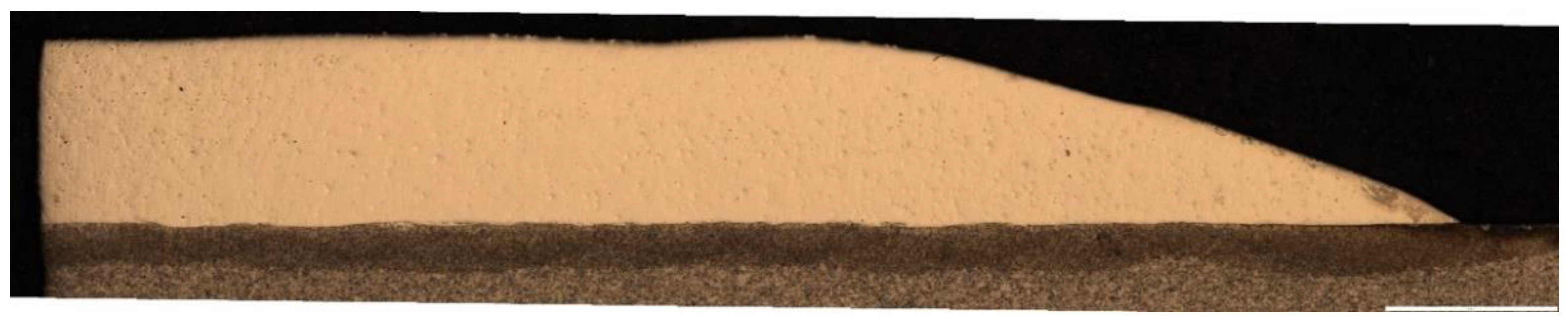
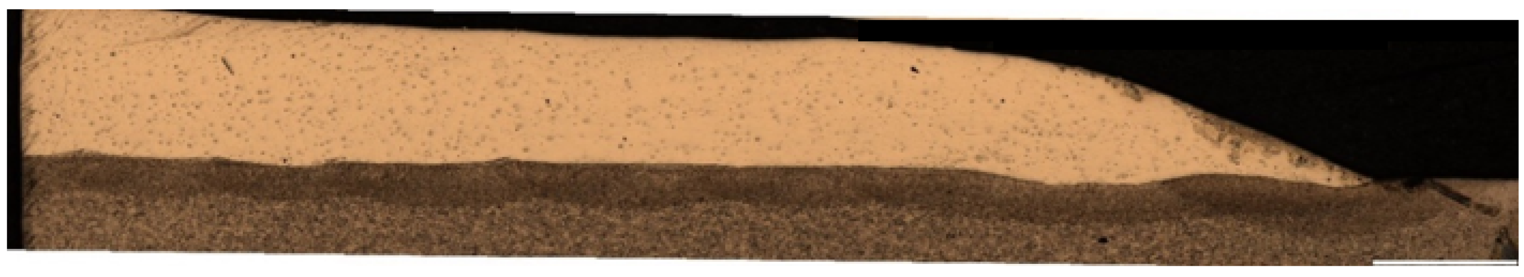
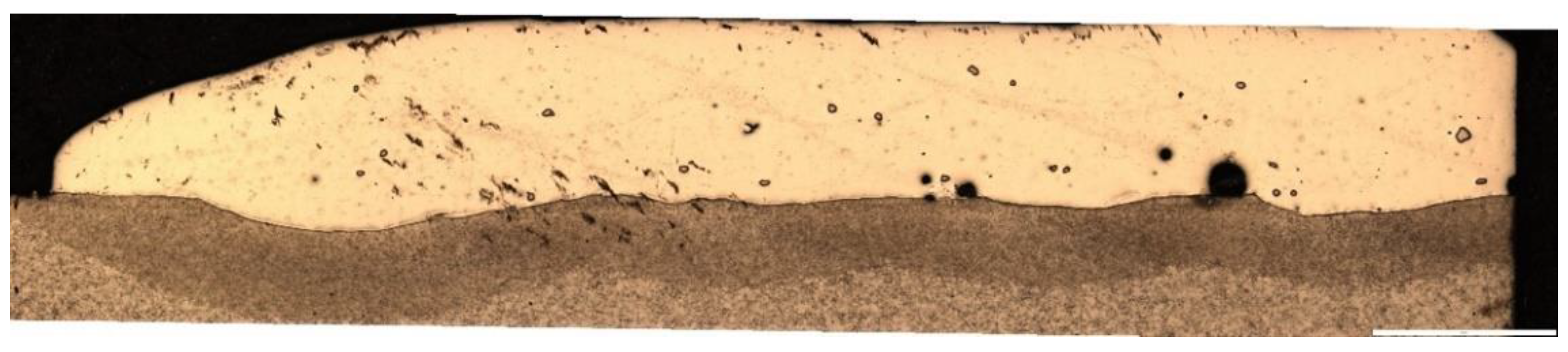
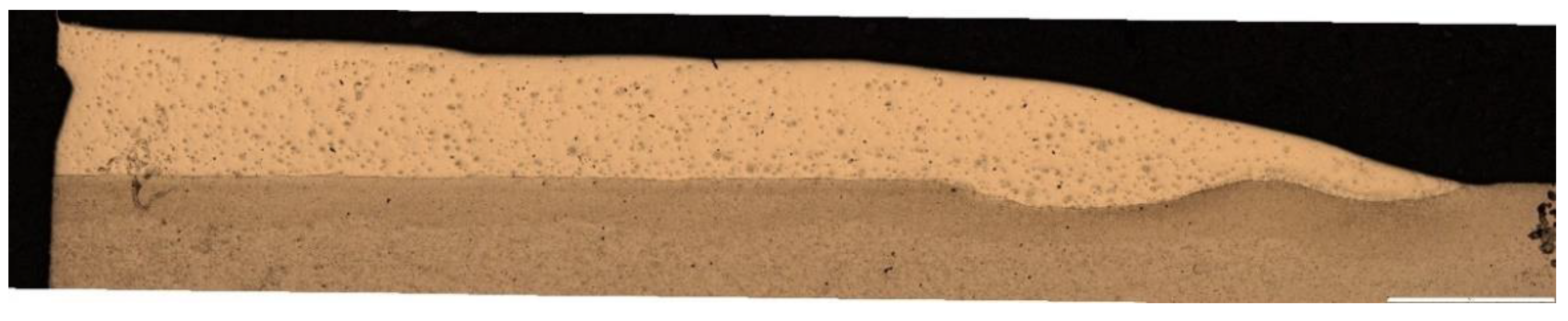
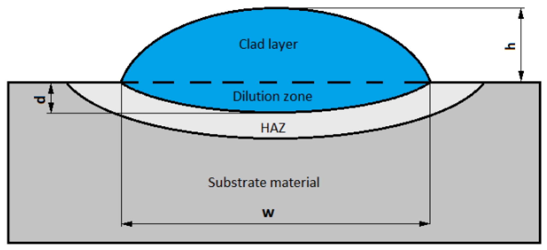
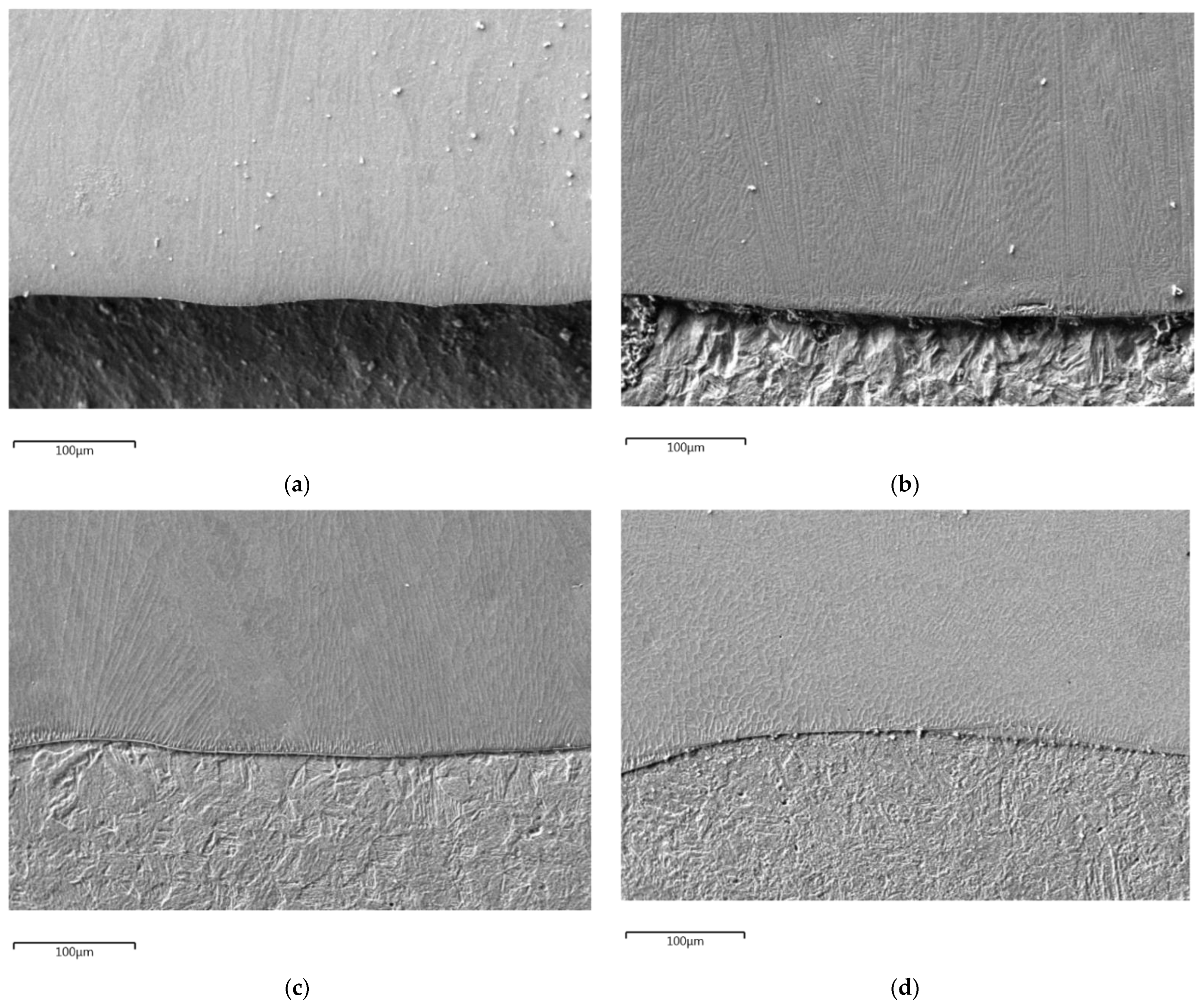
3.1. Metallographic Research

Figure 3 shows the general view of the samples made for the purposes of the tests described in the article. An example of a padding weld, made with an Inconel 718 coating material, left part of the sample after the remelting of the surface in the next stage of the process using the TIG welding method.
In the first phase, the analysis was carried out via an optical microscope produced by the Olympus company, equipped with a camera for digital recording of the image. An observation was conducted of metallographic samples of the four coatings, under ×25 magnification presented on Figure 4, Figure 5, Figure 6 and Figure 7.
To calculate the amount of dilution (D), the characteristic geometric elements (Figure 8) of the single pass were measured. Dilution was calculated using the following formula:
D = dilution   zone   area dilution   zone   area + clad   layer   area 100 %
The results of the measurements and the calculated dilution are shown in Table 3. The average values of four randomly prepared (perpendicular to the longitudinal axis) cross-sections for each kind of coatings are shown. The lowest dilution for Inconel 625 equals 1.47%, and the highest for Inconel 718 equals 6.55%. All the results are within the range ensuring adequate metallurgical joining to the substrate and furthermore, avoiding excessive dilution of the coating with the substrate material. The thicknesses shown in Table 3 show the average of the five cross-sectional measurements determined by the Olympus computer program.

3.2. Coatings Characterization by Means of SEM and EDX

The coatings characterization in the as-cladded conditions are shown in Figure 9. All of them present the homogeneous microstructure of fusion-deposited metallic coatings with visible interface between substrate and coating material. The microstructures of the interfaces in all researched coatings indicate a low dilution of coating material with the substrate. Continuous and quite sharp interface were revealed in all researched issues. No cracks, pores or other structural defects were visible. The fine-grained matrix is composed of primary dendrites. The matrix microstructure is a characteristic state formed in the conditions of nonequilibrium cooling of liquid alloys, which was also obtained in the arc surface-melting process. Table 4 compares the chemical composition of filler materials (as nominal state) and the chemical composition of deposited coatings researched by the EDX procedure. The chemical composition value of the deposited coating is the average value of three tests performed at half the thickness of the coating. The results of chemical composition comparison confirm a very low dilution of Inconel 625 and Alloy 33 and a little bit higher in the case of Inconel 718 and Stellite 6. This is clearly indicated by the increase in iron concentration on the coatings relative to the nominal material. The calculated dilution (Table 3) value of the coatings with the substrate is clearly correlated with the results of the chemical composition (Table 4) of coating materials in the nominal state and deposition by means of arc cladding.

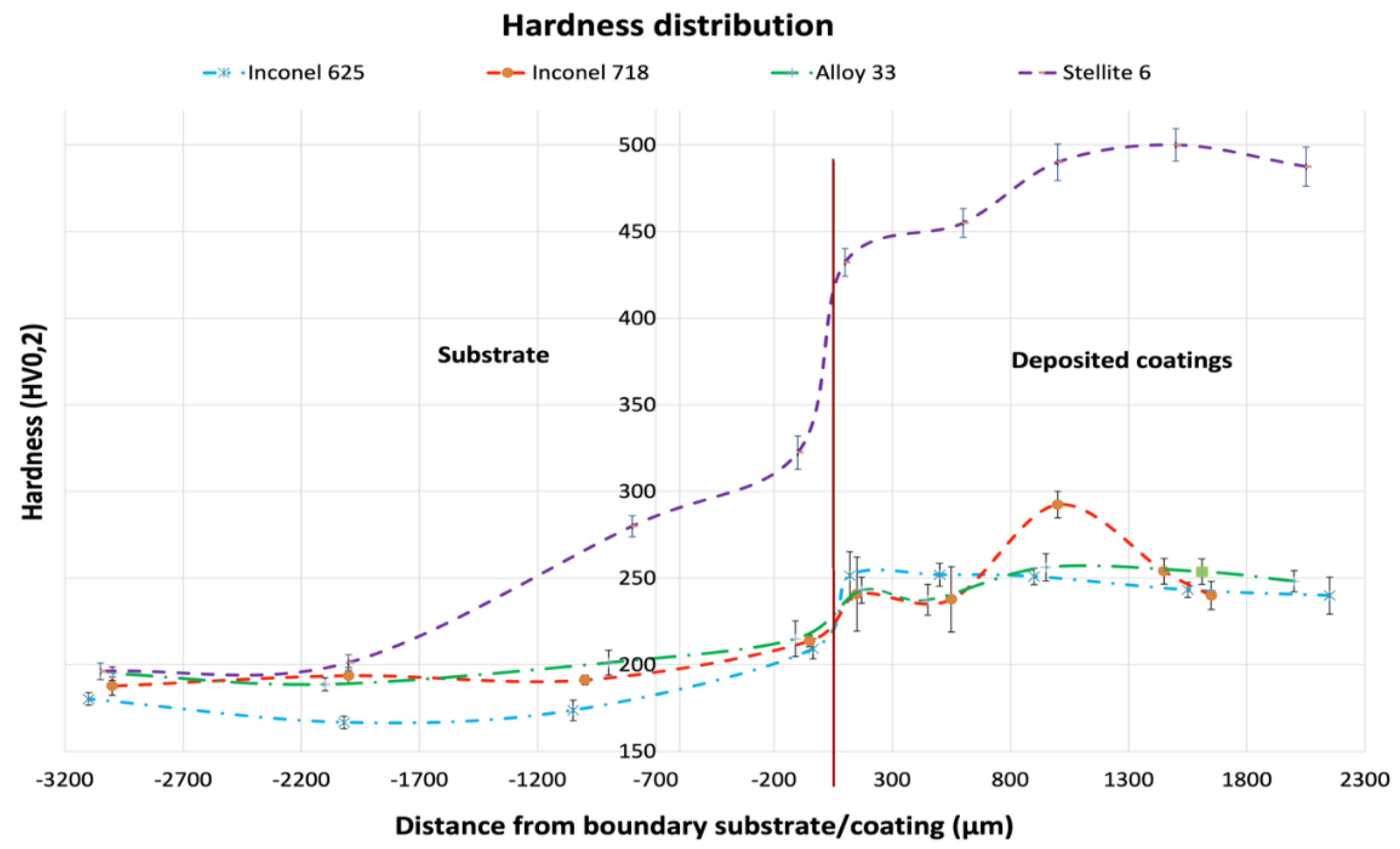
3.3. Hardness of the Coating-Substrate System

The microhardness distribution presented in Figure 10 indicates significant differences in the hardness between Stellite 6 and other investigated high nickel alloys. The Vickers HV0.2 hardness measurements were taken in accordance with EN ISO 9015:2011. Hardness of the substrate material (16Mo3 steel) is similar for all cases with a relatively small standard deviation, compared to harder HAZ (Heat Affected Zone) in substrate deposited with Stellite 6. In the deposited coatings, a nearly two times higher standard deviation from the mean values than in the base material has been recorded, which is the effect of the coarse-grained structure of the coatings crystallizing from the liquid.

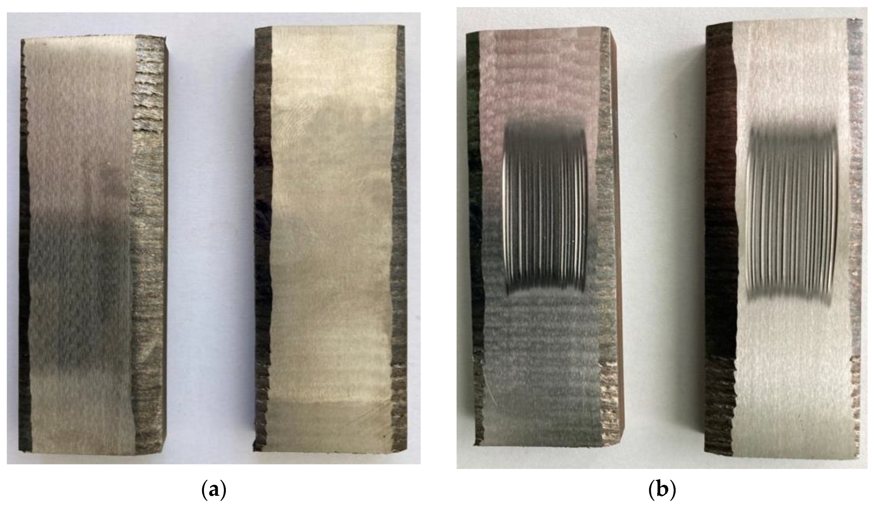
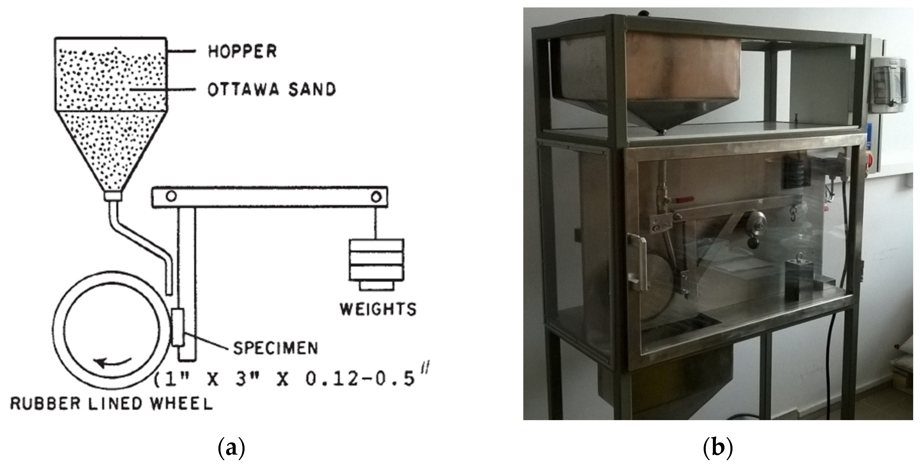
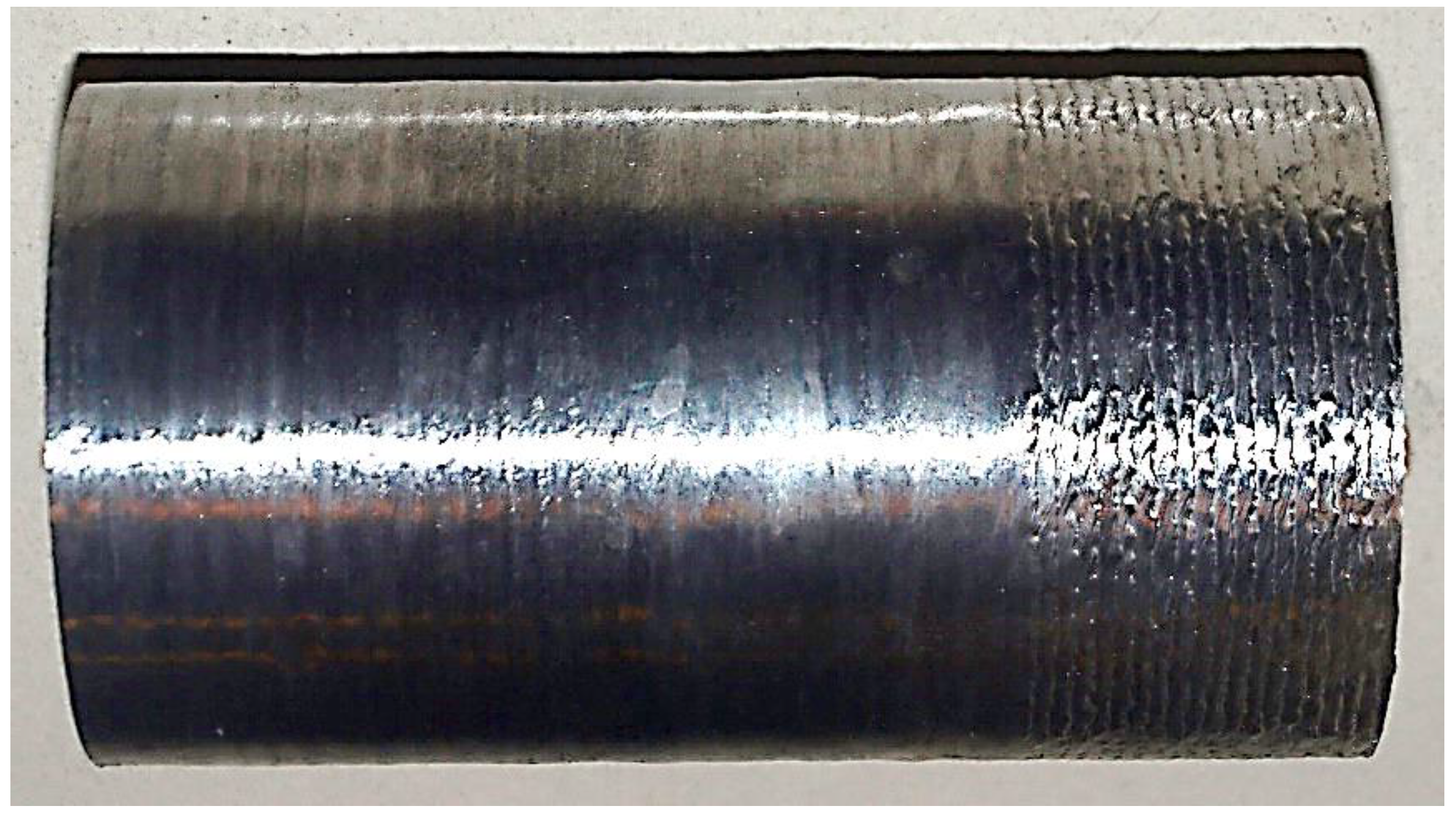
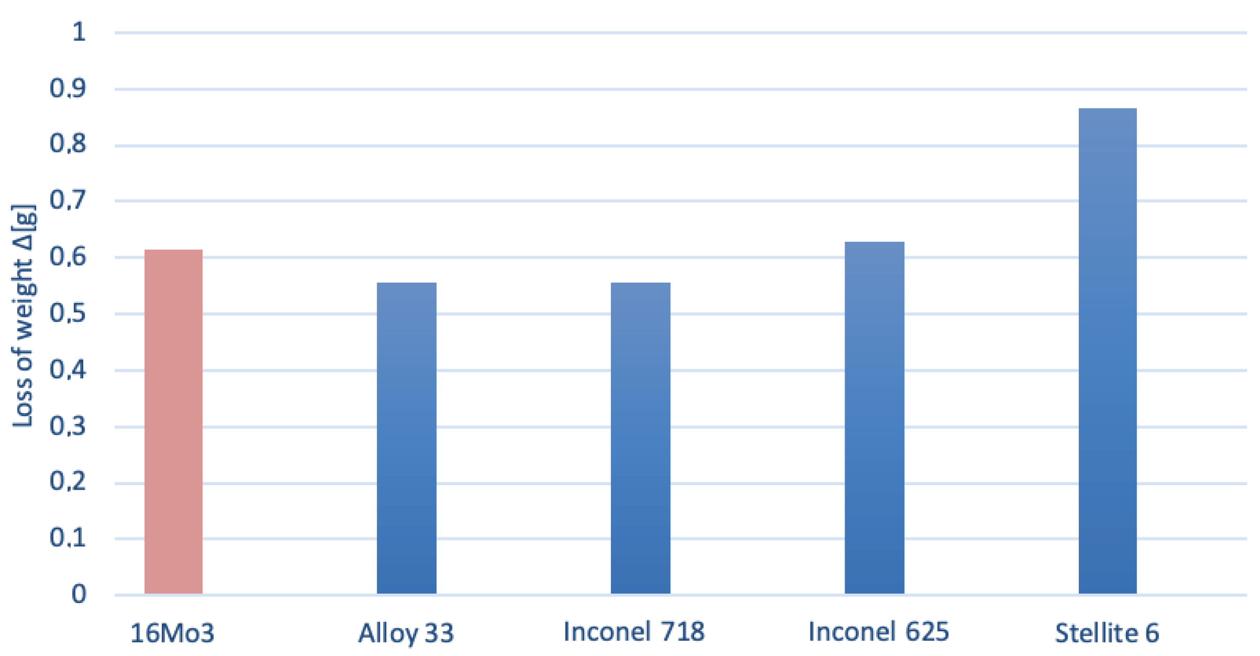
3.4. Wear Friction Resistance Test

For the abrasive wear tests, the samples were prepared according to the standard ASTM G 65 with dimensions of 25 × 76 mm. The samples were shaped on an electro erosive cutter. The thickness of the samples (substrate and coating), resulting from the surface modification technique, were different and fell within the range recommended in the standard, i.e., 3.2–12.7 mm. The surface of the samples were initially prepared by grinding in accordance with the recommendations contained in the standard ASTM G 65. The view of the prepared samples (on the example of Alloy 33) for abrasive wear tests is shown in Figure 11a,b, and shows the view of the samples after the wear abrasion test.
The abrasive wear test was performed in accordance with procedure B, which assumes the pressure of the wheel pressing against the sample at 130 N; the wheel performs 2000 revolutions during the test, which lasts 10 min, and corresponds to the friction distance of 1436 m. Before and after each test, the samples were weighed with a laboratory balance with an accuracy of 0.001 g, and the weight loss ∆g was calculated. Two samples of each material were prepared and tested. The result was presented as the mean value of two measurements. The results are presented in Table 5, and the graphic visualization is presented in Figure 12.
The observed surfaces of investigated coatings (certain samples from Inconel 625, shown for example in Figure 10) have the typical morphology of an abrasive wear resistance test. It was stated that two mechanisms are responsible for the wear of the surface. Except for the expected rolling mechanism [33], the effect of the grooving mechanism was found. This result is from shape-edge abrasive particles, which penetrated deep into the investigated surface. The effect of the penetration was a larger amount of material removed from the specimens, which initiated the grooving mechanism [34]. In contrast to the wear mechanism for the Stellite 6 coating (grooving), the rolling mechanism was predominant in the other investigated coatings.
The presented test results show that the two coatings made of Alloy 33 and Inconel 718 represent the highest abrasive wear resistance. In turn, the worst abrasive wear resistance is demonstrated by the coating produced with Stellite 6. The wear of the Stellite 6 coating in these conditions is about 30% higher than that of ordinary steel used in the construction of boilers.

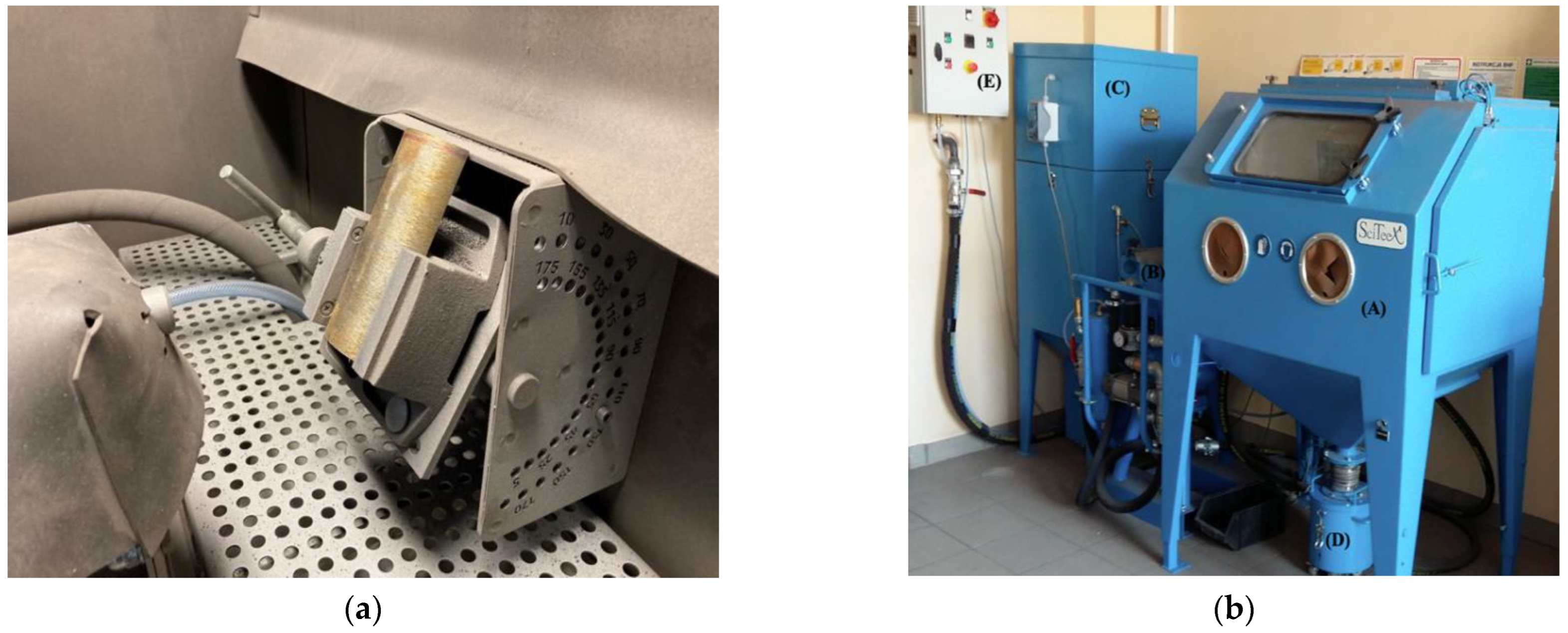
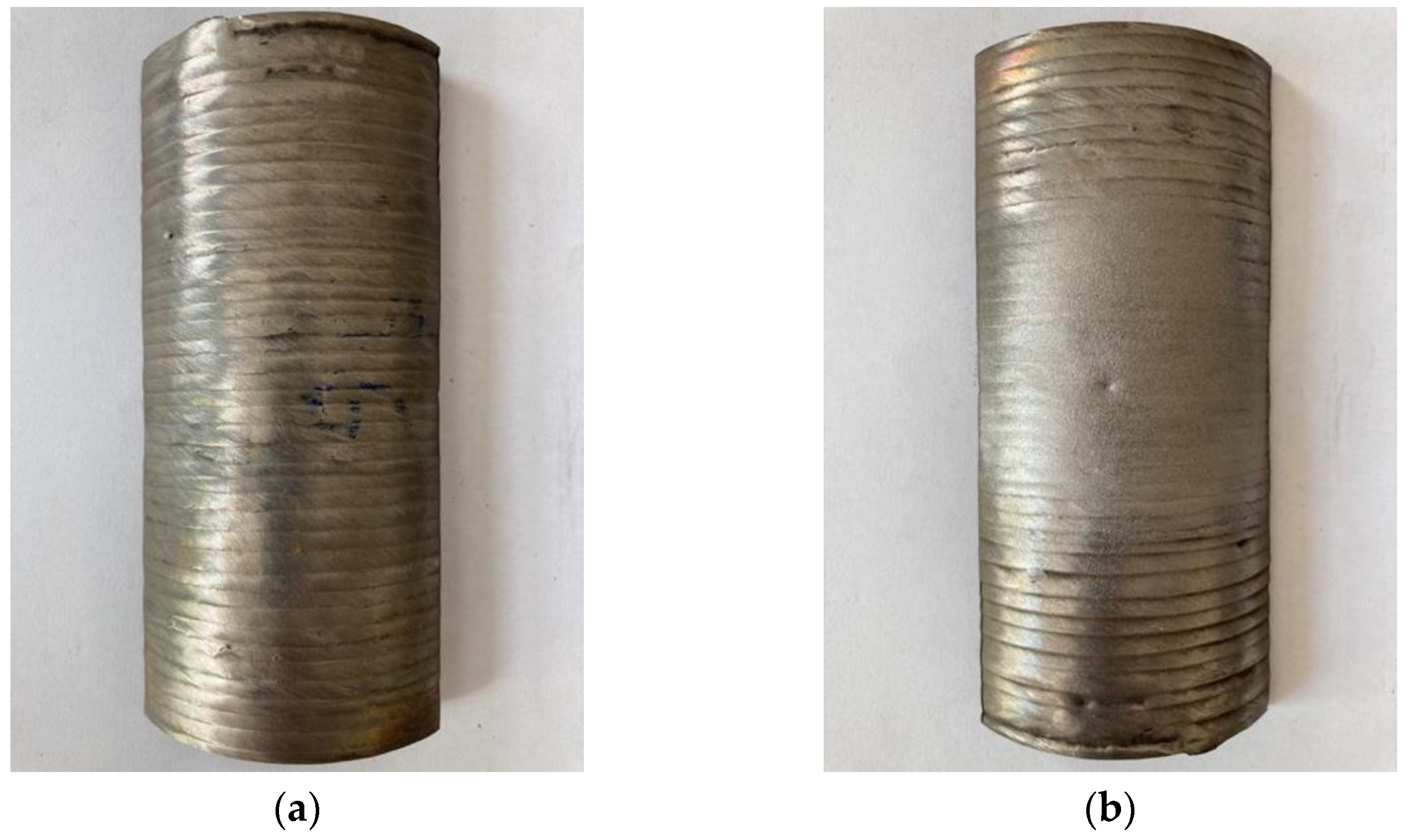
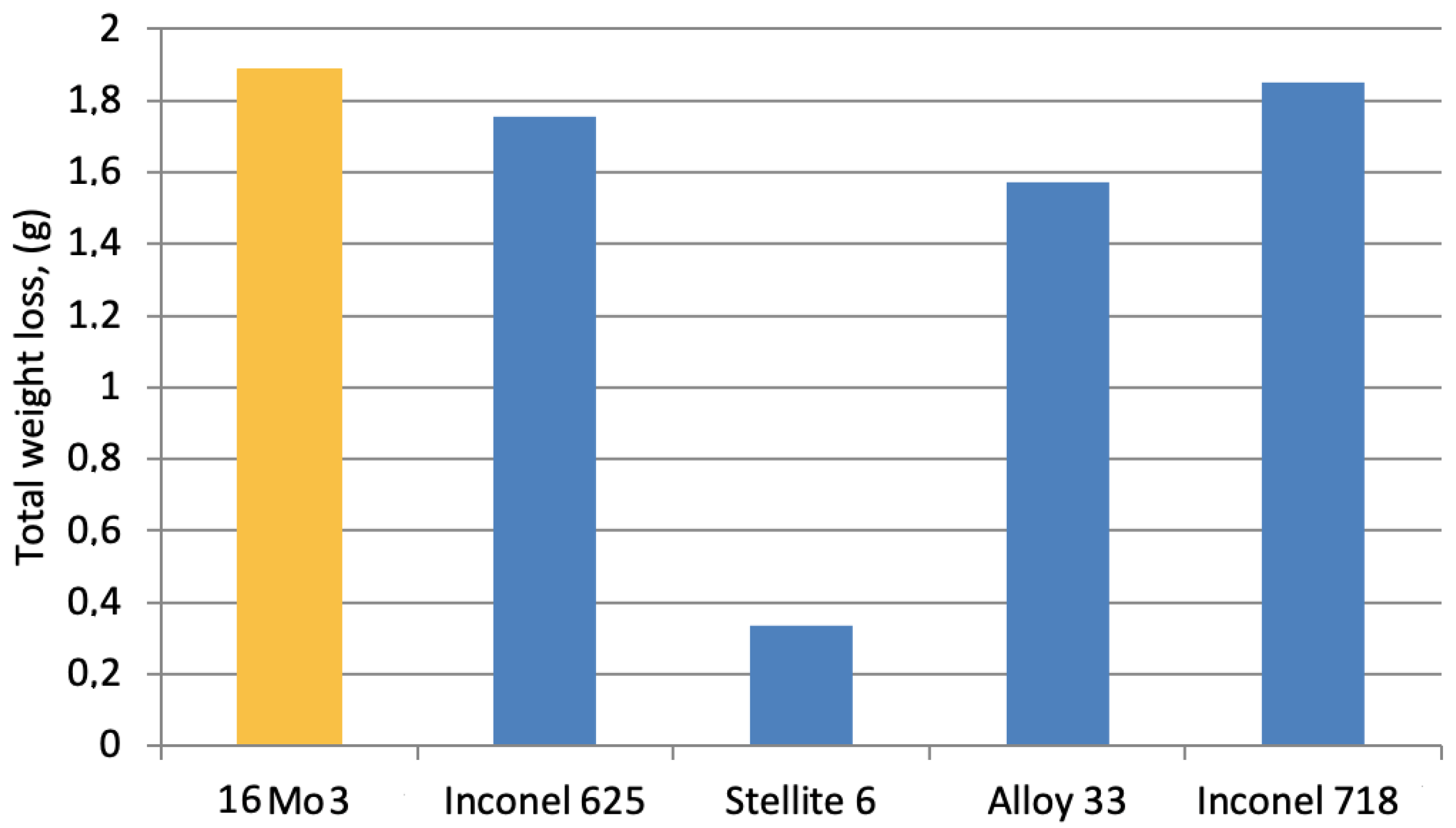
3.5. Wear Resistance under Abrasive Blasting

The tests of abrasive blasting wear resistance of the surfaced layers were carried out with the following parameters:
  • Type and granulation of the abrasive: broken steel grit WGH 40 (according to ISO 11124-3) with a hardness of 60–68 HRC, with a homogeneous martensitic and/or bainitic microstructure, with fine, well-spaced carbides, nominal fraction 0.43 mm;
  • Angle of incidence of the abrasive jet in relation to the sample surface—60°;
  • Length of blasting jet: 100 mm;
  • Diameter of pneumatic nozzle: 9 mm;
  • Air pressure supplied to the nozzle: 4.3 bar (shown on the pressure gauge);
  • Duration of the impact of the abrasive jet on the tested surface: six cycles, 10 s each.
The cladded samples with dimensions of 50 × 150 mm (half pipe) were prepared for the tests. These samples were taken from the welded pipes by means of electrical discharge cutting. The view of the prepared samples (on the example of a sample with a Stellite 6 coating) for the abrasive blasting test is shown in Figure 13a.
The research test consisted of six cycles which were performed for each material, where for each cycle, the time of the stream’s impact on the sample surface was 10 s. The total time of exposure was 60 s. After each cycle, the degree of material wear was determined as a loss of mass. For this purpose, the samples were weighed with a RADWAG PS 1000.R2 (Poland) electronic balance with an accuracy of 0.001 g. Table 6 presents the test results and their graphic visualization is shown in Figure 12. The presented data show that the Stellite 6 padding weld had the best resistance to the blasting erosive jet.
Figure 13 shows the view of the samples (Figure 13a) before and (Figure 13b) after the abrasive blasting wear test. The area of impact of the abrasive blasting stream on the tested surfaces is clearly visible. Surface wear is difficult to determine by any other method than weight loss assessment.
The results of the tests for the individual trial series (duration time 10 s), are presented in Table 5 and in the graphical form in Figure 14. The obtained data show that for the Inconel 625 deposited coating, the weight loss recorded in the subsequent treatment cycles were smaller; for the layers made of Inconel 718 it slightly increased. This effect should be related to the inhomogeneous microstructure in the thickness of the padding welds. For the remaining layers and the native material, the weight loss recorded in subsequent series was at a comparable level. The test revealed that the wear resistance of Inconel 625 and Inconel 718 during the abrasive blasting test at room temperature is close to 16Mo3, and the wear of Alloy 33. The wear resistance of the Stellite 6 coating is the highest among those compared.

4. Conclusions

Based on the experimental research carried out and discussion on the results, the following can be stated:
  • The use of the CMT hardfacing process enables the production of cladder welds with a minimal-volume fraction substrate material in coatings (small value of dilution), which results in high layer properties.
  • Among the investigated coatings, Stellite 6 layer is the hardest, at about 500 HV0.2, compared to materials such as Inconel 625, Inconel 718 and Alloy 33, which represent a cladded zone hardness about 250 HV0.2.
  • Stellite 6 layer have the lowest wear resistance in the dry sand/rubber wheel test and the highest wear resistance in the erosive blasting test. This proves the existence of different wear mechanisms in the two test methods used.
  • In the dry sand/rubber wheel test, Alloy 33 and Inconel 718 only represent higher wear resistance than substrate 16Mo3 steel.
  • In the abrasive blasting tests all coatings have a higher wear resistance than 16Mo3 steel; however, Stellite 6 coatings represents an approximately 5 times higher durability than other investigated (Inconel 625, Inconel 718 and Alloy 33) coatings.

Author Contributions

Conceptualization, P.K.; methodology, M.B.; validation, P.K., M.B. and T.C.; formal analysis, T.C.; investigation, P.K.; resources, M.B.; data curation, M.B.; writing—original draft preparation, P.K. and T.C.; writing—review and editing, T.C.; visualization, M.B.; supervision, P.K.; project administration, P.K.; funding acquisition, T.C. All authors have read and agreed to the published version of the manuscript.

Funding

This research received no external funding.

Conflicts of Interest

The authors declare no conflict of interest.

References

  1. Lindar, T.; Günen, A.; Töberling, G.; Vogt, S.; Karakas, M.S.; Löbel, M.; Lampke, T. Boriding of Laser-Clad Inconel 718 Coatings for Enhanced Wear Resistance. Appl. Sci. 2021, 11, 11935. [Google Scholar] [CrossRef]
  2. Skowrońska, B.; Sokołowski, W.; Rostamian, R. Structural investigation of the Plasma Transferred Arc hardfaced glass mold after operation. Weld. Technol. Rev. 2020, 92, 55–56. [Google Scholar] [CrossRef]
  3. Kumar, S.; Kumar, M.; Handa, A. Combating hot corrosion of boiler tubes—A study. Eng. Fail. Anal. 2018, 94, 379–395. [Google Scholar] [CrossRef]
  4. Szala, M.; Chocyk, D.; Skic, A.; Kamiński, M.; Macek, W.; Turek, M. Effect of nitrogen ion implantation on the cavitation erosion resistance and cobalt-based solid solution phase transformations of HIPed stellite 6. Materials 2021, 14, 2324. [Google Scholar] [CrossRef] [PubMed]
  5. Fabijański, M. Effect of calcium carbonate addition on mechanical properties of polylactide. Przem. Chem. 2017, 96, 894–896. [Google Scholar] [CrossRef]
  6. Włosiński, W.; Krajewski, A.; Piekoszewski, J.; Stanisławski, J.; Waliś, L. Intense pulsed plasma beams in ceramic/metal brazing. Nukleonika 2000, 45, 145–146. [Google Scholar]
  7. Bober, M.; Senkara, J.; Li, H. Comparative analysis of the phase interaction in plasma surfaced nibsi overlays with ivb and vib transition metal carbides. Materials 2021, 14, 6617. [Google Scholar] [CrossRef]
  8. Chmielewski, T.; Golański, D.; Hudycz, M.; Sałacinski, T.; Świercz, R. Surface and structural properties of titanium coating deposited onto aln ceramics substrate by friction surfacing process. Przem. Chem. 2019, 98, 208–213. [Google Scholar] [CrossRef]
  9. Kołodziejczak, P.; Golanski, D.; Chmielewski, T.; Chmielewski, M. Microstructure of rhenium doped ni-cr deposits produced by laser cladding. Materials 2021, 14, 2745. [Google Scholar] [CrossRef]
  10. Chmielewski, T.; Chmielewski, M.; Piątkowska, A.; Grabias, A.; Skowrońska, B.; Siwek, P. Phase structure evolution of the fe-al arc-sprayed coating stimulated by annealing. Materials 2021, 14, 3210. [Google Scholar] [CrossRef]
  11. Chmielewski, T.; Hudycz, M.; Krajewski, A.; Salaciński, T.; Skowrońska, B.; Świercz, R. Structure investigation of titanium metallization coating deposited onto AlN ceramics substrate by means of friction surfacing process. Coatings 2019, 9, 845. [Google Scholar] [CrossRef] [Green Version]
  12. Winczek, J.; Gucwa, M.; Mičian, M.; Koňár, R.; Parzych, S. The evaluation of the wear mechanism of high-carbon hardfacing layers. Arch. Metall. Mater. 2019, 64, 1111–1115. [Google Scholar] [CrossRef]
  13. Górka, J.; Czupryński, A.; Zuk, M.; Adamiak, M.; Kopyść, A. Properties and structure of deposited nanocrystalline coatings in relation to selected construction materials resistant to abrasive wear. Materials 2018, 11, 1184. [Google Scholar] [CrossRef] [PubMed] [Green Version]
  14. Tomków, J.; Czupryński, A.; Fydrych, D. The Abrasive Wear Resistance of Coatings Manufactured on High-Strength Low-Alloy (HSLA) Offshore Steel in Wet Welding Conditions. Coatings 2020, 10, 219. [Google Scholar] [CrossRef] [Green Version]
  15. Xin, B.; Ren, J.; Wang, X.; Zhu, L.; Gong, Y. Effect of laser remelting on cladding layer of inconel 718 superalloy formed by laser metal deposition. Materials 2020, 13, 4927. [Google Scholar] [CrossRef]
  16. Arbo, S.M.; Tomovic-Petrovic, S.; Aunemo, J.; Dahle, N.; Jensrud, O. On weldability of aerospace grade Al-Cu-Li alloy AA2065 by wire-feed laser metal deposition. J. Adv. Join. Process. 2022, 5, 100096. [Google Scholar] [CrossRef]
  17. Meng, L.; Zeng, X.; Hou, K.; Hu, Q.; Wang, D. Effect of laser cladding and laser-induction hybrid cladding coatings on the bending properties and fracture behavior of rails. Surf. Coat. Technol. 2019, 374, 1038–1050. [Google Scholar] [CrossRef]
  18. Grzybicki, M.; Jakubowski, J. Comparative tests of steel car body sheet welds made using CMT and MIG/MAG methods. Weld. Int. 2013, 27, 610–615. [Google Scholar] [CrossRef]
  19. Brezinová, J.; Džupon, M.; Viňáš, J.; Guzanová, A.; Puchý, V.; Brezina, J.; Draganovská, D.; Vojtko, M. Progressive CMT cladding for renovation of casting mold. Acta Metall. Slovaca 2020, 26, 104–110. [Google Scholar] [CrossRef]
  20. Imoudu, N.E.; Ayele, Y.Z.; Barabadi, A. The characteristic of cold metal transfer (CMT) and its application for cladding. In Proceedings of the IEEE International Conference on Industrial Engineering and Engineering Management, Singapore, 10–13 December 2017; pp. 1883–1887. [Google Scholar]
  21. Yu, W.; Tao, K.; Dai, Z.; Zhang, Y.; Chu, X. Failure Mechanism of Water Wall Coating Prepared by Supersonic Arc Spraying. J. Phys. Conf. Ser. 2022, 2168, 012019. [Google Scholar] [CrossRef]
  22. Broda, T.; Keitel, S. Resistance seam hardfacing and cladding of WC-Co in a NiCrBSi-Matrix. Weld. Technol. Rev. 2015, 88, 45–49. [Google Scholar] [CrossRef]
  23. Wegrzyn, T.; Piwnik, J.; Wszolek, L.; Tarasiuk, W. Shaft wear after surfacing with microjet cooling. Arch. Metall. Mater. 2015, 60, 2625–2630. [Google Scholar] [CrossRef]
  24. Klimpel, A. Industrial surfacing and hardfacing technology, fundamentals and applications. Weld. Technol. Rev. 2020, 91, 33–42. [Google Scholar] [CrossRef] [Green Version]
  25. Lankiewicz, K.; Baranowski, M.; Babul, T.; Kowalski, S. The study of the impact of surface preparation methods of inconel 625 and 718 nickel-base alloys on wettability by BNi-2 and BNi-3 brazing filler metals. Arch. Metall. Mater. 2015, 60, 159–165. [Google Scholar] [CrossRef] [Green Version]
  26. Selvi, S.; Vishvaksenan, A.; Rajasekar, E. Cold metal transfer (CMT) technology—An overview. Def. Technol. 2018, 14, 28–44. [Google Scholar] [CrossRef]
  27. Nandan, G.; Kumar, G.; Arora, K.S.; Kumar, A. MIG and CMT brazing of aluminum alloys and steel: A review. Mater. Today Proc. 2022, 56, 481–488. [Google Scholar] [CrossRef]
  28. Medvedovski, E.; Chinski, F.A.; Stewart, J. Wear- and corrosion-resistant boride-based coatings obtained through thermal diffusion CVD processing. Adv. Eng. Mater. 2014, 16, 713–738. [Google Scholar] [CrossRef]
  29. Doering, A.; Danks, D.; Mahmoud, S.; Scott, J. Evaluation of ASTM G65 abrasive -Spanning 13 years of sand. Wear 2011, 271, 1252–1257. [Google Scholar] [CrossRef]
  30. Kik, T.; Moravec, J.; Novakova, I. Numerical simulations of X22CrMoV12-1 steel multilayer welding. Arch. Metall. Mater. 2019, 64, 1441–1448. [Google Scholar] [CrossRef]
  31. Kik, T.; Moravec, J.; Nováková, I. Application of Numerical Simulations on 10GN2MFA Steel Multilayer Welding. In Proceedings of the Springer Proceedings in Mathematics and Statistics; 2018; Volume 249, pp. 193–204. [Google Scholar] [CrossRef]
  32. Sauraw, A.; Sharma, A.K.; Fydrych, D.; Sirohi, S.; Gupta, A.; Świerczyńska, A.; Pandey, C.; Rogalski, G. Study on microstructural characterization, mechanical properties and residual stress of gtaw dissimilar joints of p91 and p22 steels. Materials 2021, 14, 6591. [Google Scholar] [CrossRef]
  33. Chand, N.; Neogi, S. Mechanism of material removal during three-body abrasion of FRF composite. Tribol. Lett. 1998, 4, 81. [Google Scholar] [CrossRef]
  34. Singh, T.P.; Singla, A.K.; Singh, J.; Singh, K.; Gupta, M.K.; Ji, H.; Song, Q.; Liu, Z.; Pruncu, C.I. Abrasive wear behavior of cryogenically treated boron steel (30MnCrB4) used for rotavator blades. Materials 2020, 13, 436. [Google Scholar] [CrossRef] [PubMed] [Green Version]
Figure 1. (a) Dry sand/rubber wheel abrasive test schema according to ASMT G65 [29]; (b) general view of the test stand according to ASTM G65 requirements.
Applsci 12 04568 g001
Figure 2. (a) The interior of the working chamber with the sample (16Mo3 steel reference material) mounted; (b) general view of the stand for testing the abrasive blasting resistance of materials.
Applsci 12 04568 g002
Figure 3. General view of Inconel 718 coating cladded by MAG method (right side); left side after additional TIG remelting in second stage.
Applsci 12 04568 g003
Figure 4. Macrostructure of INCONEL 625 coating cladded on 16Mo3 steel tube, average thickness 2.2 mm (×25).
Applsci 12 04568 g004
Figure 5. Macrostructure of INCONEL 718 coating cladded on 16Mo3 steel tube, average thickness 1.7 mm (×25).
Applsci 12 04568 g005
Figure 6. Macrostructure of ALLOY 33 coating cladded on 16Mo3 steel tube, average thickness 2.1 mm (×25).
Applsci 12 04568 g006
Figure 7. Macrostructure of STELLITE 6 coating cladded on 16Mo3 steel tube, average thickness 2.1 mm (×25).
Applsci 12 04568 g007
Figure 8. Diagram showing geometrical parameters of a CMT cladded single bead with operating parameters from Table 1: height (h), depth (d), width (w).
Applsci 12 04568 g008
Figure 9. SEM microstructure of arc deposited coatings (a) Inconel 625; (b) Inconel 718; (c) Alloy 33; (d) Stellite 6.
Applsci 12 04568 g009
Figure 10. Distribution of microhardness in a cross-section of substrate material and the arc sprayed Fe-Al coating, before and after annealing in temperature.
Applsci 12 04568 g010
Figure 11. View of the selected examples of Inconel 625 CMT cladded coatings (a) before and (b) after the wear resistance test.
Applsci 12 04568 g011
Figure 12. Loss of weight of the materials after the abrasive wear test according to ASTM G65.
Applsci 12 04568 g012
Figure 13. View of the test specimens on the example of Stellite 6 coatings before (a) and after (b) the abrasive blasting wear test.
Applsci 12 04568 g013
Figure 14. Total loss of weight after the abrasive blasting wear test.
Applsci 12 04568 g014
Table 1. CMT cladding process parameters.
Process ParametersUnitINCONEL 718INCONEL 625ALLOY 33STELLITE 6
Travel speedmm/min26243314
Rotational speed of cladded pipeRPM13.114.512.77.2
Welding currentA243245256245
Welding arc voltageV20.52020.519
Wire feed ratem/min9.510.510.610.5
Gas flow rateL/min1514.51514
Wire diametermm1.21.21.21.2
Shielding gas-ArArArAr
Table 2. The parameters of TIG remelting cladded coatings surface.
Process ParametersUnitINCONEL 718INCONEL 625ALLOY 33STELLITE 6
Travel speedmm/min26243314
Rotational speed of cladded pipeRPM13.114.512.77.2
Welding currentA250250250250
Gas flow rateL/min16161616
Shielding gas-ArArArAr
Table 3. Average of coating’s thickness value (with standard deviation) and dilution rate calculated on the base of macroscopic research.
Coating MaterialCoating Thickness, h (mm)Dilution, D (%)
Inconel 6252.2 (0.15)1.47
Inconel 7181.7 (0.22)6.55
Alloy 332.06 (0.17)3.74
Stellite 62.1 (0.13)5.51
Table 4. Chemical composition of nominal filler material specified at standards and chemical composition measured by means of EDX in a cross-section of cladded coating, in wt%.
Coating MaterialNiCrMoCoCMnSiFeTiAlWNb + Ta
Inconel 625
nominalbase (63.43)20 ÷ 238 ÷ 100 ÷ 10 ÷ 0.10 ÷ 0.50 ÷ 0.50 ÷ 10 ÷ 0.40 ÷ 0.4-3.15 ÷ 4.15
cladded coating 1.939.42-0.1--0.810.230.17-3.94
Inconel 718
nominal50 ÷ 55 (50.68)17 ÷ 212.8–3.30 ÷ 10 ÷ 0.080 ÷ 0.350 ÷ 0.35180.65 ÷ 1.150.2 ÷ 0.8-4.75 ÷ 5.5
cladded coating 17.493.22-0.08-0.0221.45(0.92)0.49-5.5
Alloy 33
nominal30 ÷ 33 (29.04)31 ÷ 35--0 ÷ 0150 ÷ 20 ÷ 0.5Rest----
cladded coating 32.341.7-0.010.60.235.33----
Stellite 6
nominal2.528.920.013rest1.381.560.924.19--3.9-
cladded coating 27.55 1.21.10.9213.14--4.31-
Table 5. The results of the comparison of the abrasive wear of the tested CMT cladded materials.
MaterialSample No.Weight before Test, (g)Weight after Test, (g)Loss of Weight ∆g, (g)Average Value ∆g, (g)Relative 1 Abrasion Resistance
16Mo31
2
85.489
83.369
84.865
82.764
0.624
0.605
0.61450.90
Alloy 331
2
109.992
112.522
109.436
111.966
0.556
0.556
0.5561.0
Inconel 7181
2
120.581
114.15
120.007
113.611
0.574
0.539
0.55650.99
Inconel 6251
2
110.885
117.208
110.26
116.577
0.625
0.631
0.6280088
Stellite 61
2
116.431
108.292
115.575
107.413
0.856
0.879
0.86750.64
Remark 1 relative to Alloy 33.
Table 6. Results of abrasive blasting wear test.
MaterialStarting Weight (g)Loss of Weight after the Next Machining CycleTotal Weight Loss (g)Relative 1 Abrasion Resistance
10 s20 s30 s40 s50 s60 s
16Mo3348.258 347.962 347.641347.29346.997346.997346.3741.8840.17
Inconel 625387.205386.929386.636386.337386.045385.75385.4511.7540.19
Stellite 6393.318393.251 393.192393.129393.075393.023392.9830.3351
Alloy 33396.202395.994395.719395.453395.174394.898394.6281.5740.21
Inconel 718457.531457.315456.952456.638456.31456.001455.6811.850.18
Remark 1 relative to Stellite 6.
Publisher’s Note: MDPI stays neutral with regard to jurisdictional claims in published maps and institutional affiliations.

