Abstract
Terahertz (THz) imaging is a rapidly growing application motivated by industrial demands including harmless (non-ionizing) security imaging, multilayer paint quality control within the automotive industry, insulating foam non-invasive testing in aerospace, and biomedical diagnostics. One of the key components in the imaging system is the source and detector. This paper gives a brief overview of room temperature THz transceiver technology for imaging applications based on the emerging resonant tunneling diode (RTD) devices. The reported results demonstrate that RTD technology is a very promising candidate to realize compact, low-cost THz imaging systems.
1. Introduction
Terahertz imaging has attracted extensive research interests driven by industrial applications. The THz radiation between the frequency band 100 GHz to 10 THz of the electromagnetic spectrum with corresponding wavelengths from 3 mm to 30 µm shows exceptional properties including being non-ionizing (due to low photon energy) compared with X-rays and so it allows for safe inspection of various organic materials such as tissue and cells for biomedical applications [1,2]; it can penetrate materials such as fabrics, cardboard, ceramic, and plastics, offering non-invasive detection of concealed metallic and nonmetallic objects, such as plastic or liquid explosives, and contrabands [3,4,5]; and it has a shorter wavelength compared with microwave frequencies, and so provides higher spatial resolution which is particularly useful for structural defect detection such as inspection of insulating foam used in aerospace [6], corrosion detection under paint [7], and multi-layered paints thickness measurement in the automotive industry [8]. THz imaging provides these unique features when other non-destructive methods like ultrasonic, infrared, or X-ray are not applicable.
Until recently, the THz spectrum was referred to as the “THz gap” between microwave and infrared due to the lack of compact low-cost sources and detectors. In recent years with the advances in device technology, including precise semiconductor epitaxial layer growth, reliable/traceable THz test, and characterization equipment, there are now many electronic and opto-electronic devices that have started to bridge the THz gap and THz systems are significantly improved in term of the system volume, complexity, and even cost. The devices include Gunn diodes [9], IMPATT diodes [10], Schottky barrier diodes (SBDs, for frequency-multiplication) [11], heterojunction bipolar transistors (HBT) [12], resonant tunneling diodes (RTD) [13] and opto-electronic devices such as photo-mixing diodes [14,15] and quantum cascade lasers (QCL) [16].
This paper will focus on THz transceiver based on RTD technology and emerging novel compact RTD based imaging systems. It will provide an overview of the technology and its capabilities. Though not well-known, RTDs are particularly interesting and potentially useful because they are very compact, low voltage, low power demand, high output power and high power conversion efficiency [17]. They also offer a coherent source and coherent detection; this is hugely important, especially for imaging layered structures.
The paper is organized as follows: the THz imaging system is first briefly introduced in Section 2. Then the two key components of the system, the source and detector based on RTD technology and recent breakthroughs, are described in Section 3. Examples of RTD based THz imaging systems with non-destructive testing (NDT) applications and experimental results are described in Section 4. Conclusions are given in Section 5.
2. THz Imaging
The current THz imaging systems fall into two categories: active and passive imaging. Active imaging systems illuminate the target with a THz electromagnetic wave and acquire the amplitude and phase information through reflection or transmission of the signal [6]. This enables the construction of two-dimensional (2D) or three-dimensional (3D) images with high signal to noise ratio (SNR). In contrast, passive THz imaging captures the radiation that is naturally thermally emitted by or scattered from a target [18]. These two modalities have different characteristics such as contrast, resolution, dynamic ranges, and SNR.
For active THz imaging, there are two different approaches: time domain (TD) and continuous wave (CW). TD THz imaging is based on a femtosecond laser to generate ultrafast optical pulses and stimulate THz radiation (photo-Dember effect) from low bandgap semiconductors such as GaAs, InGaAs, InAs, or GaAsBi [19,20]. The THz transient normally covers very broad bandwidth extending from around 100 GHz to a few THz [19] and hence THz TD imaging can provide rich spectrum information for spectroscopy analysis. However, the system requires a complex, delicate setup with a large footprint. In contrast, CW systems probe the sample with single frequency or a narrow bandwidth signal. CW imaging affords a compact, simple, and relatively low-cost system [21]. Since it does not require complex optics such as those involved in pulsed THz TD system (THz-TDS), and it does not require a time delay scan, the image information can be processed more quickly [6,22] which is an important factor for real-time applications. One of the typical pulsed TD and CW imaging systems is shown in Figure 1. By comparison, it can be seen that the CW system significantly reduces the system complexity at the cost of adaptability due to missing spectral information of limited bandwidth [22]. The CW THz system involves many parts such as the source and detector, optical components such as lenses and mirrors to collimate the beam, a signal processing algorithm to rebuild the image, etc. This paper will only focus on the THz source/detector device technology by using the emerging RTD devices.
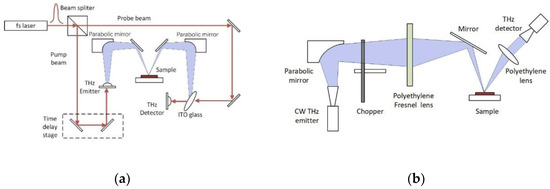
Figure 1.
(a) Schematic diagram of a pulsed TD THz imaging system. (b) Schematic diagram of a CW THz imaging system.
3. RTD THz Technology
3.1. RTD Device
RTDs are the highest frequency solid state electronic device with the fundamental frequency approaching 2 THz [13]. Its main limitation was low output power, typically in the microwatt range, but the technology is now producing THz powers in the milliwatt (mW) range, and therefore starting to enable practical applications in imaging, multi-gigabit wireless communication systems, and others [23,24,25,26]. A good review of the state-of-the-art of RTD THz technology can be found in [27].
An RTD is a one-dimensional vertical transport unipolar two terminal semiconductor device. Figure 2a shows the typical layer structure of an RTD in the InP-based material system. The core of the device consists of a low bandgap semiconductor, in this case the indium gallium arsenide (InGaAs, Eg = 0.738 meV) quantum well layer, sandwiched by high bandgap semiconductor layers, in this case the aluminum arsenide (AlAs, Eg = 2.949 meV) layers, forming the so-called double barrier quantum well (DBQW) structure. The DBQW is nanometric in dimensions, typically under 10 nm, and so the energy states in the quantum well are quantized, i.e., only certain energy levels are allowed [28], and therefore also allowing quantum mechanical tunnelling of the electrons through the structure. The possibility of electrons tunnelling through the barriers is defined by the transmission coefficient, which is related to the alignment of the electron energies with the allowed energy states in the quantum well. Figure 2b shows the conduction band profile under forward bias corresponding to the peak resonant/current condition. In the illustration, the first and second quasi-bound resonant energy levels E1 and E2 are shown. The current through the DBQW increases with applied bias at low voltages up to the peak current/voltage corresponding to the resonant energy (E1) when the transmission coefficient is close to unity. Here, the electrons entering the DBQW have the same energy as the allowed energy level in the quantum well, and so the highest/peak current is reached. With further increase in bias, that transmission coefficient drops due to mismatch between the electron energies and E1 and so the current drops with bias creating the negative differential resistance (NDR) region in the current-voltage I-V characteristic. At higher bias still, corresponding to valley current/voltage, the electrons have higher energy compared to the barriers and therefore the current increases again with bias. Thus, the RTD is characterized by a highly non-linear I-V characteristic comprising an NDR region and positive differential resistance (PDR) regions, as illustrated in Figure 2c. The precise shape of the I-V characteristic depends on different elements such as the device size, material composition, epitaxial structure, and the temperature.

Figure 2.
(a) Typical InGaAs/AlAs RTD epilayer diagram. (b) The corresponding conduction band diagram under forward bias. The discrete quantized resonant energy levels E1 and E2 are denoted in the quantum well. (c) Typical RTD I-V characteristic with the bias regions for use as a transmitter (Tx) or receiver (Rx) as shown.
The span of the NDR region determines the maximum radio frequency (RF) power the diode can deliver to a load and this can be approximated by [29]. The actual RF output power would depend on various factors such as the operation frequency, device and circuit parasitic elements and impedance matching. In [30], the relation between the device output power with an optimal load in an oscillator circuit was derived. Using this relationship, simulation shows that 2 mW power at 300 GHz and 1 mW power at 800 GHz could be achieved for single RTD oscillator with an optimal load as shown in Figure 3. Recent experimental results show that this performance is becoming achievable [31,32].
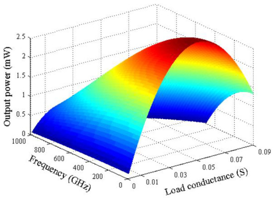
Figure 3.
Simulated RTD output power versus frequency and load conductance. Reprinted with permission from Ref. [30].
The RTD operating frequency is limited by both extrinsic RC (resistance-capacitance) time constant and the intrinsic quasibound-state lifetime. Efforts have been reported to minimize the device series resistance (R) and capacitance (C) as well as the dwell time (τdwell) and transition time (τdep) [33,34,35]. RTD has been demonstrated with very wide broadband intrinsic frequency response from 120 GHz to 3.9 THz [35] and the estimated intrinsic cut-off frequency is 4.6 THz with respect to τdwell = 33 fs and τdep = 38 fs for the specific epilayer design in [36]. Therefore, RTDs can be embedded in resonators to build up sub-millimeter-wave or terahertz continuous wave sources and highly sensitive detectors.
3.2. RTD THz Source
The first RTD THz source operating at 420 GHz with 0.2 µW output power was demonstrated by a research group at Massachusetts Institute of Technology in 1989 [37], and this was followed by a 712 GHz (0.3 µW) source in 1991 [38]. There was a lull in RTD research until in 2010 when research group at Tokyo University of Technology reported a 1 THz (7 µW) source [39]. The nano-sized (0.39 µm2) RTD device was integrated with a slot antenna as shown in Figure 4a [40]. The InP chip was mounted on silicon hemispherical lens to collimate the THz beam. By using this approach, 1.98 THz with 40 nW output power was achieved in [41]. In the sub-THz range, 1 mW at 0.26 THz was reported in [31] where a single RTD was integrated with a microstrip resonator (see Figure 4b).
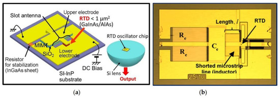
Figure 4.
(a) Structure of 1.92 THz RTD transmitter including the RTD chip was mounted on a silicon hemispherical lens (Reprinted with permission from [38]). (b) Structure of 1 mW 260 GHz RTD transmitter (Reprinted with permission from [40]).
RTD arrays have also been developed for the purpose of power; combining 0.61 mW at 620 GHz was reported in [32] when two RTD-slot antenna element arrays were employed. The researchers of [42] reported 0.73 mW at 1 THz when 89 RTD-slot-dipole antenna element arrays were integrated. A dipole antenna was placed over the slot resonator and coupled the radiation power away from the high permittivity substrate. The array was operated in pulsed mode and multiple spectrum peaks were observed due to lack of synchronization between all elements.
3.3. RTD THz Detector
Besides THz source or emitter, the other crucial component in the imaging system is the THz detector. Responsivity, noise equivalent power (NEP), response time, and capability for array integration are the key factors for imaging applications. In general, THz detectors can be classified into two categories: thermal detectors and rectification detectors. Thermal detectors include an acousto-optic detector, e.g., Golay cell, which consists of an enclosed chamber in which the changing of gas volume due to radiation heating is measured; and a bolometer detector that measures the changes of properties such as conductivity, temperature, or electrical polarization (pyroelectric detectors). Thermal detectors have the advantage of very broad bandwidth, but the response time is relatively slow (0.1–0.01 s) making them unsuitable for real-time imaging applications [43].
Rectifying THz detectors normally utilize the non-linear characteristic of devices such as a Schottky barrier diode (SBD) detector [44,45], field effect transistor (FET) detectors by utilizing stimulated plasma wave [46], or photoconductive antenna (PCA) detectors that introduce the transient voltage drop over the gap of antenna on photoconductive substate (e.g., LT-GaAs) [47] and metamaterial detectors due to artificial negative refractive index [48,49]. The advantages of using rectifying THz detectors include the ability to provide coherent detection, enabling both amplitude and phase information to be extracted. They also show relatively high responsivity (kV/W), low noise equivalent power (NEP) of 10−12 to 10−11 W/√Hz, and fast response time of a few picoseconds [43,45,50,51].
RTD devices show strong non-linear characteristics as described in the previous section. There are two working modes for RTD detector: direct and indirect (coherent) mode. For direct detection, the RTD is biased in the non-linear region at zero bias (for triple barrier variant) or at peak voltage as depicted in Figure 2c. The input THz electromagnetic wave is strongly rectified following square law detection, i.e., the output current is proportional to the square of the input signal voltage [52]. The highest reported InP RTD detector responsivity is 4 kV/W at 0.35 THz [53] and 80 V/W at 0.76 THz, with the RTD biased near the peak-current voltage (Vp) [54]. In [55], it was reported that RTD detector showed four times higher responsivity compared to a commercial SBD detector at 300 GHz. It is worth mentioning that the dynamic range of an RTD direct detector is limited since the input RF amplitude should not shift the RTD bias point into the NDR region, as that will cause DC instability. A triple barrier (TB) RTD has also been proposed as a high responsivity zero-bias detector. It has demonstrated strong non-linear characteristic near zero bias voltage and gave 66 kV/W responsivity at 280 GHz [56].
For the coherent mode detection, RTD oscillator acts as a LO when the RTD is biased in the active NDR region. If the received signal has the frequency and amplitude within the locking range of the RTD LO, injection locking will take place, resulting in homodyne detection due to self-mixing [57,58]. Coherent detection has shown up to a 40 dB improvement of the detected power compared with direct detection [58].
4. Compact RTD THz Imaging and Other NDT Systems
The RTD THz transceiver has been widely reported for next generation ultrahigh speed wireless communication system towards 100 Gbps [23,24,25,57,59]. The application of RTD technology in THz imaging systems and other non-destructive testing (NDT) applications is just emerging but is under fast development. A prototype compact 300 GHz RTD camera was proposed in [60]. The size of the camera is comparable to a coin as shown in Figure 5a. Inside the package, the InP RTD transceiver is mounted on Si hemispherical lens as shown in Figure 5d. The camera package integrates a collimation lens to improve the beam profile.
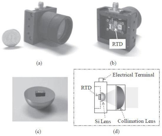
Figure 5.
(a) Front view of the RTD camera package. (b) Rear view of the RTD camera package. (c) 300 GHz RTD chip on Si-hemispherical lens. (d) Schematic diagram of the package. Reprinted with permission from Ref. [60].
Both transmission and reflection imaging systems have been proposed using the RTD camera as shown in Figure 6. The system setup details can be found in [60]. The proposed 300 GHz RTD reflection system successfully mapped the concealed objects inside a plastic box with a 1.0 mm spatial resolution. Also, the imaging system based on a Michelson interferometer was demonstrated for the first time with estimated depth resolution of around 1 µm. These results make RTDs a very promising candidate for compact THz imaging systems.
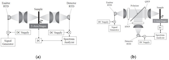
Figure 6.
(a) THz transmission imaging system using RTD transceiver. (b) THz reflection imaging system using RTD transceiver. Reprinted with permission from Ref. [60].
In [61], a simplified 345 GHz RTD reflection imaging system was proposed. The system diagram is shown in Figure 7. Compared with traditional coherent tomography (OCT) imaging system [62], the proposed system significantly simplifies the setup by eliminating the use of integrated reference mirror, THz source, beam splitter, and detector. Instead, it only uses one single RTD transceiver. The working principle of RTD transmitter and detector (coherent) has been explained in Section 2 and Section 3. The RTD transceiver was placed 30 cm in front of an elliptical mirror reflector and the imaging stage was placed around 40 cm apart. The detected signal was extracted through a bias-tee and then amplified by a low noise amplifier (LNA), a lock-in amplifier, and then final analog-digital (A/D) converter to digitize the signals. The preliminary results demonstrated 2D imaging with high resolution of 0.1 mm, which is smaller than a quarter of the wavelength at 345 GHz [61]. Although the mechanical chopper was employed in the setup in Figure 7, the RTD source can be on-off modulated simply through the DC bias. The modulation speed is up to tens of GHz [23,24], which will make the imaging system more practical for industrial applications by eliminating the chopping mechanism.
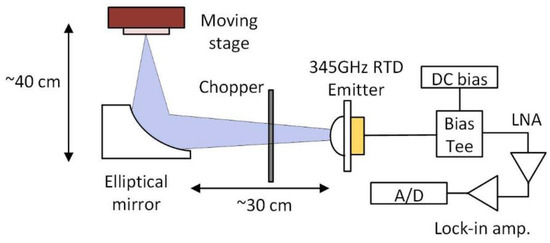
Figure 7.
Schematic diagram of a single RTD transceiver THz imaging system. Adapted with permission from Ref. [61].
Another important emerging application is RTD-based THz radar, including amplitude-modulated continuous-wave (AMCW) where the THz wave amplitude is modulated by sinusoidal signal superimposed on the DC bias of RTD [63,64,65,66], and subcarrier frequency modulated continuous wave (FMCW) radar, where again the amplitude of THz is modulated with linearly sweeping frequencies [26,67].
For AMCW, the reflected signal is demodulated by envelope detector (SBD) with the phase difference measured. The phase shifting carries the depth information and matches the movement of the target. For FMCW, the operating principle is different from normal FMCW radar in which the carrier frequency is swept [68]. The reason is due to the difficulty of linearly sweeping the RTD carrier frequencies using current technology. The preliminary experimental results in [26,63,64,65,66,67] demonstrate that RTD radars are capable of precise distance measurement with very low ranging error (µm range). With further improvements of the system, such as a high power RTD source, varactor diode integrated RTD VCO, high responsivity and low NEP detector, and better signal and data processing algorithm, the RTD THz radar technique can rapidly evolve to the next level to realize long-distance high precision THz radar with compact size and low power consumption.
Since RTDs have narrow linewidths, an RTD voltage-control oscillator (VCO) array has been proposed to cover frequencies from 420 GHz to 970 GHz [69]. This was used in absorbance measurements with the setup as shown in Figure 8, where RTD VCOs is composed of seven individual RTD oscillators covering different frequency bands. The THz wave radiated from RTD VCO is collimated by an off-axis parabolic mirror and transmitted through a specimen, which is an allopurinol pellet; i.e., a medicine used to lower levels of uric acid in blood. The detector utilized is a liquid-He-cooled Si composite bolometer. The system successfully demonstrated the detection of allopurinol with absorption peak at around 700 GHz. The achieved results show agreement with TDS measurements. The system setup could be more compact and even simpler if the bolometer was replaced by another type of non-cryogenic detector, e.g., an RTD detector.
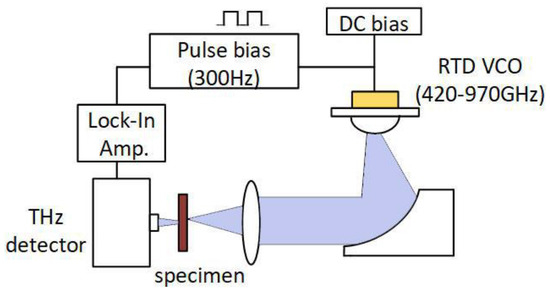
Figure 8.
Schematic diagram of wide bandwidth RTD spectroscope system. Adapted with permission from Ref. [69].
5. Conclusions
The applications of THz imaging systems have long been limited to scientific research due to the bulky size, complex and complicated optics setup, and high cost; however, with the fast development of THz devices and components, THz imaging is becoming one of the fast-developing areas transiting from lab to real-life applications, in particular non-destructive testing and condition monitoring. It is preferable for applications where traditional methods such as X-ray, infrared, or ultrasonic are not applicable. Those include harmless (non-ionizing) security imaging, multilayer paint quality control within the automotive industry, insulating foam non-invasive testing in aerospace, and biomedical diagnostics. In this paper, THz imaging systems based on room temperature transceiver technology using RTDs have been briefly reviewed. The advantages of RTD transceiver include simple structure, compact size, room temperature operation, and potentially several mW output power to cover the THz spectrum region. The RTD detector also shows high responsivity with fast response time and availability of coherent detection. These features make RTD a very promising candidate for compact low-cost THz CW imaging systems that are easy to implement as part of an industrial production line or for condition monitoring of plant and engineering structures.
Author Contributions
J.W., writing—original draft preparation; M.N. and E.W., writing—review and editing. All authors have read and agreed to the published version of the manuscript.
Funding
The work on RTD technology at Glasgow University reported in the paper was partly funded by the Engineering and Physical Sciences Research Council (UK), grant no. EPSRC EP/S009442/1.
Institutional Review Board Statement
Not applicable.
Informed Consent Statement
Not applicable.
Data Availability Statement
Publicly available datasets were analyzed in this study. This data can be found at https://www.gla.ac.uk/research/enlighten/ (accessed on 2 April 2022).
Conflicts of Interest
The authors declare no conflict of interest.
References
- Tabata, H. Application of Terahertz Wave Technology in the Biomedical Field. IEEE Trans. Terahertz Sci. Technol. 2015, 5, 1146–1153. [Google Scholar]
- Fan, S.; He, Y.; Ung, B.S.; Pickwell-MacPherson, E. The growth of biomedical terahertz research. J. Phys. D Appl. Phys. 2014, 47, 374009. [Google Scholar] [CrossRef]
- Sheen, D.; Hall, T.; Severtsen, R.; McMakin, D.; Hatchell, B.; Valdez, P.L. Active Wideband 350 GHz Imaging System for Concealed-Weapon Detection (Spie Defense, Security, and Sensing); SPIE: Orlando, FL, USA, 2009; Volume 7309. [Google Scholar]
- Ahmed, S.S. Advanced fully-electronic personnel security screening technology. In Proceedings of the 2015 9th European Conference on Antennas and Propagation (EuCAP), Lisbon, Portugal, 13–17 April 2015; pp. 1–4. [Google Scholar]
- Wang, Z.; Chang, T.; Cui, H. Review of Active Millimeter Wave Imaging Techniques for Personnel Security Screening. IEEE Access 2019, 7, 148336–148350. [Google Scholar] [CrossRef]
- Karpowicz, N.; Zhong, H.; Zhang, C.; Lin, K.-I.; Hwang, J.-S.; Xu, J.; Zhang, X.-C. Compact continuous-wave subterahertz system for inspection applications. Appl. Phys. Lett. 2005, 86, 054105. [Google Scholar] [CrossRef]
- Anastasi, R.F.; Madaras, E.I. Terahertz NDE for Under Paint Corrosion Detection and Evaluation. AIP Conf. Proc. 2006, 820, 515–522. [Google Scholar] [CrossRef]
- Krimi, S.; Klier, J.; Jonuscheit, J.; Freymann, G.v.; Urbansky, R.; Beigang, R. Highly accurate thickness measurement of multi-layered automotive paints using terahertz technology. Appl. Phys. Lett. 2016, 109, 021105. [Google Scholar] [CrossRef]
- Khalid, A.; Dunn, G.M.; Macpherson, R.F.; Thoms, S.; Macintyre, D.; Li, C.; Steer, M.J.; Papageorgiou, V.; Thayne, I.G.; Kuball, M.; et al. Terahertz oscillations in an In0.53Ga0.47As submicron planar Gunn diode. J. Appl. Phys. 2014, 115, 114502. [Google Scholar] [CrossRef]
- Banerjee, S. Chapter 1—THz Solid-State Source Based on IMPATT Devices. In Terahertz Biomedical and Healthcare Technologies; Banerjee, A., Chakraborty, B., Inokawa, H., Nath Roy, J., Eds.; Elsevier: Amsterdam, The Netherlands, 2020; pp. 1–41. [Google Scholar] [CrossRef]
- Maestrini, A.; Thomas, B.; Wang, H.; Jung, C.; Treuttel, J.; Jin, Y.; Chattopadhyay, G.; Mehdi, I.; Beaudin, G. Schottky diode-based terahertz frequency multipliers and mixers. Comptes Rendus Phys. 2010, 11, 480–495. [Google Scholar] [CrossRef]
- Urteaga, M.; Griffith, Z.; Seo, M.; Hacker, J.; Rodwell, M.J.W. InP HBT Technologies for THz Integrated Circuits. Proc. IEEE 2017, 105, 1051–1067. [Google Scholar] [CrossRef]
- Maekawa, T.; Kanaya, H.; Suzuki, S.; Asada, M. Oscillation up to 1.92 THz in resonant tunneling diode by reduced conduction loss. Appl. Phys. Express 2016, 9, 024101. [Google Scholar] [CrossRef]
- Sasaki, Y.; Yokoyama, H.; Ito, H. Dual-wavelength optical-pulse source based on diode lasers for high-repetition-rate, narrow-bandwidth terahertz-wave generation. Opt. Express 2004, 12, 3066–3071. [Google Scholar] [CrossRef] [PubMed]
- Song, H.; Hwang, S.; An, H.; Song, H.-J.; Song, J.-I. Continuous-wave THz vector imaging system utilizing two-tone signal generation and self-mixing detection. Opt. Express 2017, 25, 20718–20726. [Google Scholar] [CrossRef] [PubMed]
- Williams, B.S. Terahertz quantum-cascade lasers. Nat. Photonics 2007, 1, 517–525. [Google Scholar] [CrossRef]
- Cornescu, A.C.; Morariu, R.; Ofiare, A.; Al-Khalidi, A.; Wang, J.; Figueiredo, J.M.L.; Wasige, E. High-Efficiency Bias Stabilization for Resonant Tunneling Diode Oscillators. IEEE Trans. Microw. Theory Tech. 2019, 67, 3449–3454. [Google Scholar] [CrossRef]
- Petkie, D.T.; Casto, C.; De Lucia, F.C.; Murrill, S.R.; Redman, B.; Espinola, R.L.; Franck, C.C.; Jacobs, E.L.; Griffin, S.T.; Halford, C.E.; et al. Active and passive imaging in the THz spectral region: Phenomenology, dynamic range, modes, and illumination. J. Opt. Soc. Am. B 2008, 25, 1523–1531. [Google Scholar] [CrossRef]
- Krotkus, A. Semiconductors for terahertz photonics applications. J. Phys. D Appl. Phys. 2010, 43, 273001. [Google Scholar] [CrossRef]
- Biswas, A.; Banerjee, A.; Acharyya, A.; Inokawa, H.; Roy, J.N. Emerging Trends in Terahertz Solid-State Physics and Devices: Sources, Detectors, Advanced materials, and Light-Matter Interactions; Springer: Singapore, 2020. [Google Scholar]
- Lee, I.-M.; Kim, N.; Lee, E.S.; Han, S.-P.; Moon, K.; Park, K.H. Frequency modulation based continuous-wave terahertz homodyne system. Opt. Express 2015, 23, 846–858. [Google Scholar] [CrossRef]
- Karpowicz, N.; Zhong, H.; Xu, J.; Lin, K.-I.; Hwang, J.-S.; Zhang, X.C. Comparison between pulsed terahertz time-domain imaging and continuous wave terahertz imaging. Semicond. Sci. Technol. 2005, 20, S293–S299. [Google Scholar] [CrossRef]
- Wang, J.; Al-Khalidi, A.; Wang, L.; Morariu, R.; Ofiare, A.; Wasige, E. 15-Gb/s 50-cm Wireless Link Using a High-Power Compact III–V 84-GHz Transmitter. IEEE Trans. Microw. Theory Tech. 2018, 66, 4698–4705. [Google Scholar] [CrossRef]
- Oshima, N.; Hashimoto, K.; Suzuki, S.; Asada, M. Wireless data transmission of 34 Gbit/s at a 500-GHz range using resonant-tunnelling-diode terahertz oscillator. Electron. Lett. 2016, 52, 1897–1898. [Google Scholar] [CrossRef]
- Oshiro, A.; Nishigami, N.; Yamamoto, T.; Nishida, Y.; Webber, J.; Fujita, M.; Nagatsuma, T. PAM4 48-Gbit/s Wireless Communication Using a Resonant Tunneling Diode in the 300-GHz Band. IEICE Electron. Express 2021, 19, 20210494. [Google Scholar] [CrossRef]
- Dobroiu, A.; Suzuki, S.; Asada, M. Terahertz-Wave Radars Based on Resonant-Tunneling-Diode Oscillators (Spie Optical Engineering + Applications); SPIE: San Diego, CA, USA, 2019; Volume 11124. [Google Scholar]
- Cimbri, D.; Wang, J.; Al-Khalidi, A.; Wasige, E. Resonant Tunnelling Diodes High-Speed Terahertz Wireless Communications—A Review. IEEE Trans. Terahertz Sci. Technol. 2022, 1. [Google Scholar] [CrossRef]
- Davies, J.H. The Physics of Low-Dimensional Semiconductors: An Introduction; Cambridge University Press: Cambridge, UK, 1997. [Google Scholar] [CrossRef]
- Kim, C.; Brandli, A. High-Frequency High-Power Operation of Tunnel Diodes. IRE Trans. Circuit Theory 1961, 8, 416–425. [Google Scholar] [CrossRef]
- Wang, L. Output Power Analysis and Simulations of Resonant Tunneling Diode Based Oscillators. In Proceedings of the System Simulation and Scientific Computing, Berlin/Heidelberg, Germany, 27–30 October 2012; pp. 47–55. [Google Scholar]
- Al-Khalidi, A.; Alharbi, K.H.; Wang, J.; Morariu, R.; Wang, L.; Khalid, A.; Figueiredo, J.M.L.; Wasige, E. Resonant Tunneling Diode Terahertz Sources With up to 1 mW Output Power in the J-Band. IEEE Trans. Terahertz Sci. Technol. 2020, 10, 150–157. [Google Scholar] [CrossRef]
- Suzuki, S.; Shiraishi, M.; Shibayama, H.; Asada, M. High-Power Operation of Terahertz Oscillators With Resonant Tunneling Diodes Using Impedance-Matched Antennas and Array Configuration. IEEE J. Sel. Top. Quantum Electron. 2013, 19, 8500108. [Google Scholar] [CrossRef]
- Konishi, Y.; Allen, S.T.; Reddy, M.; Rodwell, M.J.W.; Smith, R.P.; Liu, J. AlAs/GaAs Schottky-collector resonant-tunnel-diodes. Solid-State Electron. 1993, 36, 1673–1676. [Google Scholar] [CrossRef]
- Sollner, T.C.L.G.; Goodhue, W.D.; Tannenwald, P.E.; Parker, C.D.; Peck, D.D. Resonant tunneling through quantum wells at frequencies up to 2.5 THz. Appl. Phys. Lett. 1983, 43, 588–590. [Google Scholar] [CrossRef]
- Scott, J.S.; Kaminski, J.P.; Wanke, M.; Allen, S.J.; Chow, D.H.; Lui, M.; Liu, T.Y. Terahertz frequency response of an In0.53Ga0.47As/AlAs resonant-tunneling diode. Appl. Phys. Lett. 1994, 64, 1995–1997. [Google Scholar] [CrossRef]
- Asada, M.; Suzuki, S.; Kishimoto, N. Resonant Tunneling Diodes for Sub-Terahertz and Terahertz Oscillators. Jpn. J. Appl. Phys. 2008, 47, 4375–4384. [Google Scholar] [CrossRef]
- Brown, E.R.; Sollner, T.C.L.G.; Parker, C.D.; Goodhue, W.D.; Chen, C.L. Oscillations up to 420 GHz in GaAs/AlAs resonant tunneling diodes. Appl. Phys. Lett. 1989, 55, 1777–1779. [Google Scholar] [CrossRef]
- Brown, E.R.; Söderström, J.R.; Parker, C.D.; Mahoney, L.J.; Molvar, K.M.; McGill, T.C. Oscillations up to 712 GHz in InAs/AlSb resonant-tunneling diodes. Appl. Phys. Lett. 1991, 58, 2291–2293. [Google Scholar] [CrossRef]
- Suzuki, S.; Asada, M.; Teranishi, A.; Sugiyama, H.; Yokoyama, H. Fundamental oscillation of resonant tunneling diodes above 1 THz at room temperature. Appl. Phys. Lett. 2010, 97, 242102. [Google Scholar] [CrossRef]
- Asada, M.; Suzuki, S. Terahertz Emitter Using Resonant-Tunneling Diode and Applications. Sensors 2021, 21, 1384. [Google Scholar] [CrossRef] [PubMed]
- Izumi, R.; Suzuki, S.; Asada, M. 1.98 THz resonant-tunneling-diode oscillator with reduced conduction loss by thick antenna electrode. In Proceedings of the 2017 42nd International Conference on Infrared, Millimeter, and Terahertz Waves (IRMMW-THz), Cancun, Mexico, 27 August–1 September 2017; pp. 1–2. [Google Scholar]
- Kasagi, K.; Suzuki, S.; Asada, M. Large-scale array of resonant-tunneling-diode terahertz oscillators for high output power at 1 THz. J. Appl. Phys. 2019, 125, 151601. [Google Scholar] [CrossRef]
- Sizov, F. Terahertz radiation detectors: The state-of-the-art. Semicond. Sci. Technol. 2018, 33, 123001. [Google Scholar] [CrossRef]
- Schlecht, E.; Siles, J.V.; Lee, C.; Lin, R.; Thomas, B.; Chattopadhyay, G.; Mehdi, I. Schottky Diode Based 1.2 THz Receivers Operating at Room-Temperature and Below for Planetary Atmospheric Sounding. IEEE Trans. Terahertz Sci. Technol. 2014, 4, 661–669. [Google Scholar] [CrossRef]
- Han, S.-P.; Ko, H.; Park, J.-W.; Kim, N.; Yoon, Y.-J.; Shin, J.-H.; Kim, D.Y.; Lee, D.H.; Park, K.H. InGaAs Schottky barrier diode array detector for a real-time compact terahertz line scanner. Opt. Express 2013, 21, 25874–25882. [Google Scholar] [CrossRef]
- Dyakonov, M.I.; Shur, M.S. Plasma wave electronics: Novel terahertz devices using two dimensional electron fluid. IEEE Trans. Electron Devices 1996, 43, 1640–1645. [Google Scholar] [CrossRef]
- Warren, A.C.; Katzenellenbogen, N.; Grischkowsky, D.; Woodall, J.M.; Melloch, M.R.; Otsuka, N. Subpicosecond, freely propagating electromagnetic pulse generation and detection using GaAs:As epilayers. Appl. Phys. Lett. 1991, 58, 1512–1514. [Google Scholar] [CrossRef][Green Version]
- Tao, H.; Kadlec, E.A.; Strikwerda, A.C.; Fan, K.; Padilla, W.J.; Averitt, R.D.; Shaner, E.A.; Zhang, X. Microwave and terahertz wave sensing with metamaterials. Opt. Express 2011, 19, 21620–21626. [Google Scholar] [CrossRef]
- Carranza, I.E.; Grant, J.P.; Gough, J.; Cumming, D. Terahertz Metamaterial Absorbers Implemented in CMOS Technology for Imaging Applications: Scaling to Large Format Focal Plane Arrays. IEEE J. Sel. Top. Quantum Electron. 2017, 23, 1–8. [Google Scholar] [CrossRef]
- Kurita, Y.; Ducournau, G.; Coquillat, D.; Satou, A.; Kobayashi, K.; Tombet, S.B.; Meziani, Y.M.; Popov, V.V.; Knap, W.; Suemitsu, T.; et al. Ultrahigh sensitive sub-terahertz detection by InP-based asymmetric dual-grating-gate high-electron-mobility transistors and their broadband characteristics. Appl. Phys. Lett. 2014, 104, 251114. [Google Scholar] [CrossRef]
- Otsuji, T. Trends in the Research of Modern Terahertz Detectors: Plasmon Detectors. IEEE Trans. Terahertz Sci. Technol. 2015, 5, 1110–1120. [Google Scholar]
- Pozar, D.M. Microwave Engineering, 4th ed.; Wiley: Hoboken, NJ, USA, 2011. [Google Scholar]
- Yu, X.; Kim, J.-Y.; Fujita, M.; Nagatsuma, T. Efficient mode converter to deep-subwavelength region with photonic-crystal waveguide platform for terahertz applications. Opt. Express 2019, 27, 28707–28721. [Google Scholar] [CrossRef] [PubMed]
- Takida, Y.; Suzuki, S.; Asada, M.; Minamide, H. Sensitivity Measurement of Resonant-Tunneling-Diode Terahertz Detectors. In Proceedings of the 2019 44th International Conference on Infrared, Millimeter, and Terahertz Waves (IRMMW-THz), Paris, France, 1–6 September 2019; pp. 1–2. [Google Scholar]
- Shiode, T.; Mukai, T.; Kawamura, M.; Nagatsuma, T. Giga-bit wireless communication at 300 GHz using resonant tunneling diode detector. In Proceedings of the Asia-Pacific Microwave Conference 2011, Melbourne, VIC, Australia, 5–8 December 2011; pp. 1122–1125. [Google Scholar]
- Arzi, K.; Clochiatti, S.; Suzuki, S.; Rennings, A.; Erni, D.; Weimann, N.; Asada, M.; Prost, W. Triple-Barrier Resonant-Tunnelling Diode THz Detectors with on-chip antenna. In Proceedings of the 2019 12th German Microwave Conference (GeMiC), Stuttgart, Germany, 25–27 March 2019; pp. 17–19. [Google Scholar]
- Nishigami, N.; Nishida, Y.; Diebold, S.; Kim, J.; Fujita, M.; Nagatsuma, T. Resonant Tunneling Diode Receiver for Coherent Terahertz Wireless Communication. In Proceedings of the 2018 Asia-Pacific Microwave Conference (APMC), Kyoto, Japan, 6–9 November 2018; pp. 726–728. [Google Scholar]
- Nishida, Y.; Nishigami, N.; Diebold, S.; Kim, J.; Fujita, M.; Nagatsuma, T. Terahertz coherent receiver using a single resonant tunnelling diode. Sci. Rep. 2019, 9, 18125. [Google Scholar] [CrossRef] [PubMed]
- Oshima, N.; Hashimoto, K.; Suzuki, S.; Asada, M. Terahertz Wireless Data Transmission With Frequency and Polarization Division Multiplexing Using Resonant-Tunneling-Diode Oscillators. IEEE Trans. Terahertz Sci. Technol. 2017, 7, 593–598. [Google Scholar] [CrossRef]
- Miyamoto, T.; Yamaguchi, A.; Mukai, T. Terahertz imaging system with resonant tunneling diodes. Jpn. J. Appl. Phys. 2016, 55, 032201. [Google Scholar] [CrossRef]
- Yi, L.; Kaname, R.; Nishida, Y.; Yu, X.; Fujita, M.; Nagatsuma, T. Imaging Applications with a Single Resonant Tunneling Diode Transceiver in 300-GHz Band. In Proceedings of the 2020 International Topical Meeting on Microwave Photonics (MWP), Matsue, Japan, 24–26 November 2020; pp. 120–123. [Google Scholar]
- Fujimoto, J.G.; Pitris, C.; Boppart, S.A.; Brezinski, M.E. Optical coherence tomography: An emerging technology for biomedical imaging and optical biopsy. Neoplasia 2000, 2, 9–25. [Google Scholar] [CrossRef]
- Dobroiu, A.; Wakasugi, R.; Suzuki, S.; Asada, M. Toward a solid-state, compact, terahertz-wave radar. AIP Conf. Proc. 2019, 2067, 020004. [Google Scholar] [CrossRef]
- Dobroiu, A.; Wakasugi, R.; Shirakawa, Y.; Suzuki, S.; Asada, M. Amplitude-modulated continuous-wave radar in the terahertz band using a resonant-tunneling-diode oscillator. In Proceedings of the 2019 44th International Conference on Infrared, Millimeter, and Terahertz Waves (IRMMW-THz), Paris, France, 1–6 September 2019; pp. 1–2. [Google Scholar]
- Dobroiu, A.; Wakasugi, R.; Shirakawa, Y.; Suzuki, S.; Asada, M. Absolute and Precise Terahertz-Wave Radar Based on an Amplitude-Modulated Resonant-Tunneling-Diode Oscillator. Photonics 2018, 5, 52. [Google Scholar] [CrossRef]
- Dobroiu, A.; Wakasugi, R.; Shirakawa, Y.; Suzuki, S.; Asada, M. Amplitude-modulated continuous-wave radar in the terahertz range using lock-in phase measurement. Meas. Sci. Technol. 2020, 31, 105001. [Google Scholar] [CrossRef]
- Shirakawa, Y.; Dobroiu, A.; Suzuki, S.; Asada, M.; Ito, H. Principle of a Subcarrier Frequency-modulated Continuous-wave Radar in the Terahertz Band Using a Resonant-tunneling-diode Oscillator. In Proceedings of the 2019 44th International Conference on Infrared, Millimeter, and Terahertz Waves (IRMMW-THz), Paris, France, 1–6 September 2019; pp. 1–2. [Google Scholar]
- Jaeschke, T.; Bredendiek, C.; Pohl, N. A 240 GHz ultra-wideband FMCW radar system with on-chip antennas for high resolution radar imaging. In Proceedings of the 2013 IEEE MTT-S International Microwave Symposium Digest (MTT), Seattle, WA, USA, 2–7 June 2013; pp. 1–4. [Google Scholar]
- Kitagawa, S.; Mizuno, M.; Saito, S.; Ogino, K.; Suzuki, S.; Asada, M. Frequency-tunable resonant-tunneling-diode terahertz oscillators applied to absorbance measurement. Jpn. J. Appl. Phys. 2017, 56, 058002. [Google Scholar] [CrossRef]
Publisher’s Note: MDPI stays neutral with regard to jurisdictional claims in published maps and institutional affiliations. |
© 2022 by the authors. Licensee MDPI, Basel, Switzerland. This article is an open access article distributed under the terms and conditions of the Creative Commons Attribution (CC BY) license (https://creativecommons.org/licenses/by/4.0/).