Study Protocol

Study on Frost Resistance of the Carbon-Fiber-Reinforced Concrete

1
College of Aerospace and Civil Engineering, Harbin Engineering University, Harbin 150001, China
2
School of Water Conservancy and Civil Engineering, Northeast Agricultural University, Harbin 150030, China
3
School of Mining Engineering, Heilongjiang University of Science and Technology, Harbin 150022, China
*
Author to whom correspondence should be addressed.
Appl. Sci. 2022, 12(8), 3823; https://doi.org/10.3390/app12083823
Submission received: 22 February 2022 / Revised: 31 March 2022 / Accepted: 6 April 2022 / Published: 10 April 2022
(This article belongs to the Topic Fiber-Reinforced Cementitious Composites)

Abstract

:
Frost resistance is a very important durability criterion of concrete in the cold environment. To improve the frost resistance of concrete, carbon fiber was added into the concrete. Repeated soaking in water will accelerate the freeze-thaw damage of concrete, resulting in mass loss and the compressive strength decrease of the concrete. Thus, a recurrent freeze-thaw experiment, in which specimens of carbon-fiber-reinforced concrete were frozen for 4 h and then thawed in the warm water for 4h, was carried out to estimate the relationship of the addition of carbon fiber and frost resistance. The results show that adding the carbon fiber into concrete could reduce the mass loss of the concrete during the freeze-thaw experiment. And when the carbon fiber content is more than 0.50 wt.‰, the increase in the carbon fiber content improved the compressive strength of the concrete significantly. The frost-resistance of the plain concrete is 100 freeze–thaw cycles, after which the compressive strength losses were 21.2% and 9.0%, respectively. When the optimal adding amount of carbon is 1.5 wt.%, the frost-resistance of the concrete is 250 cycles. It indicates that the carbon-fiber-reinforced concrete is suitable for buildings in cold and moist conditions.

1. Introduction

About half of concrete buildings have different degrees of freeze–thaw damage worldwide [1]. Globally, in cold regions, such as Northern Europe, Russia, Canada, Japan, and the northern part of the United States, concrete structures have different degrees of freeze–thaw damage, and the cost for maintenance and reinforcement is quite significant [1]. The economic loss caused by the freeze–thaw damage of buildings is much higher than the construction cost [1]. Concrete structures are often subjected to freeze–thaw cycles, and their mechanical properties and durability will be reduced by various degrees or even damaged, especially in a salt-rich environment [2]. Thus, it is highly necessary to study how to improve the frost resistance of concrete.
However, very limited data is available in the literature on the frost resistance performance of fiber reinforced concrete [2]. Adding polypropylene fibers into concrete could slightly increase the frost resistance of concrete, as argued by Karahan et al. [3]. According to Yu et al.’s [4] study, the addition steel fibers can improve frost resistance. To improve the performance of concrete, various fiber-reinforced concretes (FRCs) that are made of cement, water, aggregate, and dispersed fibers e.g., synthetic fibers, steel fibers, glass fibers, polypropylene fibers, and carbon fibers, are extensively used [5,6,7]. At present, steel fibers, carbon fibers, and polypropylene fibers are the most common materials for FRC [6]. Steel FRC has a high compressive strength, crack resistance, and toughness [7,8]. However, steel fibers can easily rust in humid and corrosive environments. The addition of steel fibers decreases the flowability of FRC to some extent, which would reduce the workability of the FRC significantly. The addition of polypropylene fibers can greatly improve the non-deformability of the concrete, increase the toughness, and improve the fatigue and impact resistance [2]. The strength of polypropylene FRC is also improved by a small degree. However, owing to the low elastic modulus, unmodified polypropylene fibers do not bond to concrete very well. Carbon fibers have many advantages, such as a high elastic modulus and strength, low density, and fatigue and corrosion resistance. The carbon fibers added to the concrete improve the strength [9,10], crack resistance [11], and flexural resistance [12] of the concrete. The CFRC was also resistant to high temperatures [13]. However, the aforementioned studies mainly concentrated on the mechanical properties of CFRC at room or high temperature, while little experimental research and analysis has been conducted on the frost resistance of CFRC at low temperature conditions.
The volume fraction of the fibers influences the mechanical properties of the concrete, e.g., strength, toughness, impact resistance and so on [7,8,9,10,11,12]. This study primarily examines the effects of the carbon fiber content on the frost resistance of CFRC at low temperatures, and estimates the correlation of the amount of fiber and frost resistance. It would provide a scientific reference for improving the frost resistance of concrete under cold conditions.

2. Experimental Program of CFRC
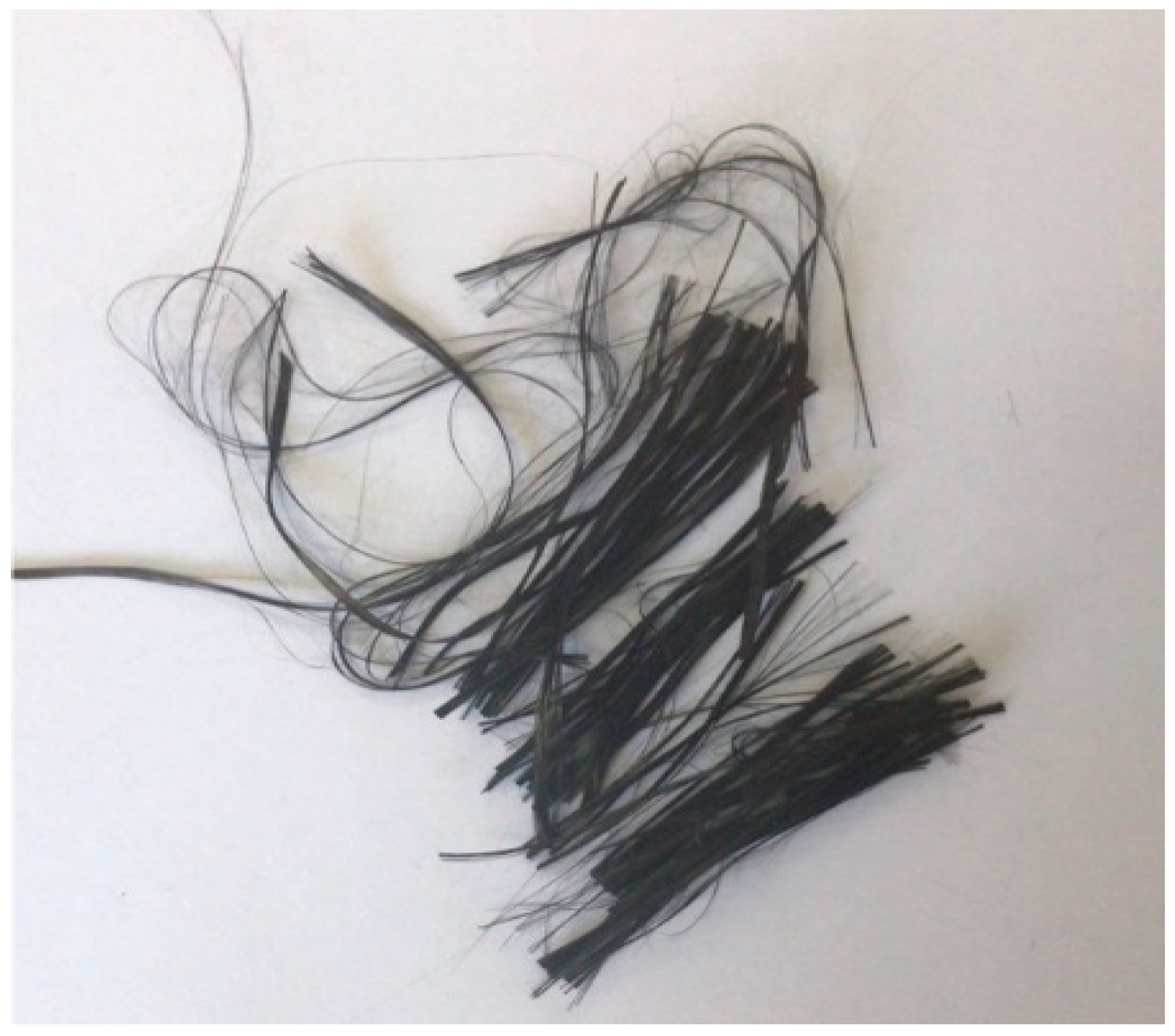
2.1. Materials

Ordinary Portland cement (C) with a grade of 32.5R (P·O 32.5), which was produced by Yatai Group Harbin Cement Co., Ltd. (Harbin, China), was used to prepare the concrete. Its density is 3.0 g/cm3. The fineness of cement expressed by the specific surface area is 3100–3300 cm2/g. The initial setting time and final setting time are more than 45 min and less than 10 h, respectively.
Natural medium-coarse sand with a fineness modulus (MX) of 2.1–3.4 was used for the fine aggregate (FA).
Crushed stone was adopted for the coarse aggregate (CA), whose maximum grain size was 16 mm.
To eliminate the chlorine, the tap water was placed for three days then used to mix concrete.
Carbon fibers (T700) produced by Toho Co., Ltd. (Tokyo, Japan), were used (Figure 1). The physical properties of the carbon fibers are listed in Table 1.
Being a kind of hydrophobic material, carbon fiber agglomerates easily in cement-based grout, so carboxymethyl cellulose was used as a dispersant (D), and whose mixing weight was one-fiftieth of a dose of water.
A high-efficiency water-reducing agent (HRWR) was also adopted to improve the workability of the CFRC. A defoaming agent (DA), tributyl phosphate, was utilized to reduce the number of bubbles in the concrete.

2.2. Mix Proportion

The weight ratio for the plain concrete was chosen to be 1:1.5:3.8 (C:FA:CA) with a water–cement ratio of 0.4 (Table 2). The carbon fiber content was varied, with the amount of 0.6 kg/m3 (0.25 ‰ of the total weight, abbreviated as 0.25 wt.‰), 1.2 kg/m3 (0.5 wt.‰), 2.4 kg/m3 (1.0 wt.‰), 3.6 kg/m3 (1.5 wt.‰), and 4.8 kg/m3 (2.0 wt.‰). The specimen was given a name that represents the amount of carbon fiber used in the specimen. For example, the specimen CF0.25 represents the CFRC specimen whose carbon fiber content was 0.25 wt.‰. Meanwhile, the plain concrete specimens were compared with the CFRC specimens, which were named PC for short.

2.3. Preparation of Specimens
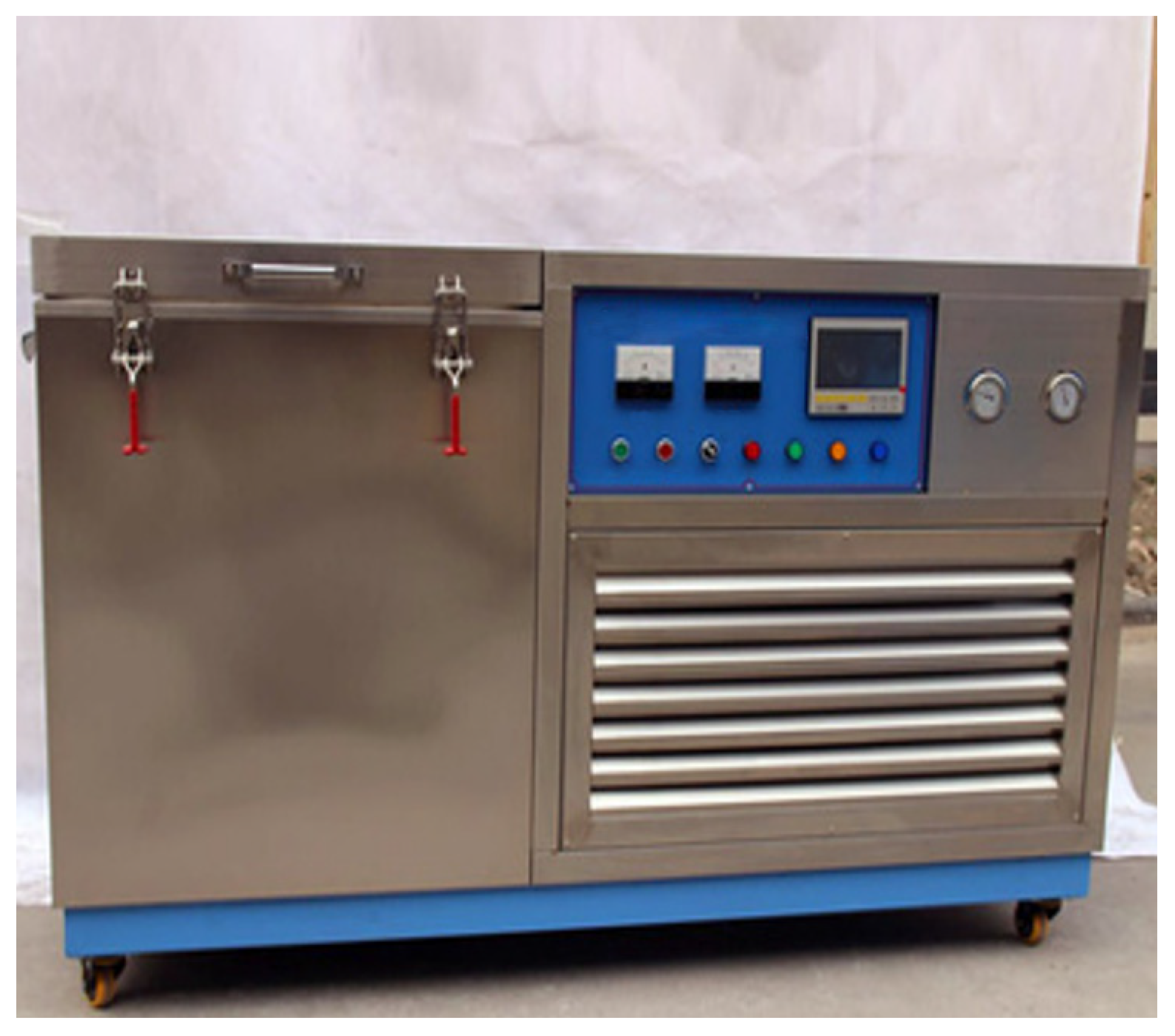
Each material was weighed according to the design proportion of the concrete mixture with an accuracy of 0.5 wt.%. The carbon fiber, dispersant, and water were mixed and dispersed by a vibration of ultrasonic waves for 5 min to produce a carbon fiber solution. The cement, fine aggregate, coarse aggregate, water-reducing agent, and defoaming agent were mixed uniformly by an agitator, and then the carbon fiber solution was poured into the agitator and stirred for three minutes. The well-proportioned concrete was poured into plastic molds with dimensions of 100 mm × 100 mm × 100 mm. Subsequently, fresh concrete mixtures in plastic molds were vibrated and compacted on a vibrating table. After 48 h, the mold forms of the concrete specimens were removed and the specimens were kept at the room temperature. Twenty-one specimens were made for each kind of concrete. A total of 126 concrete specimens, including 21 PC specimens and 105 CFRC specimens, were prepared.

2.4. Test Procedure

The test process for the frost resistance of each concrete specimen strictly complied with the Standard for Test Methods of Long-Term Performance and Durability of Ordinary Concrete [14]. To saturate the specimens, the 24-day concrete specimens were placed into 20 °C water for four days. The 28-day specimens were cleaned, and the water on surface was wiped off. After weighing, three specimens from each type of concrete were selected for compression tests. Simultaneously, the remaining specimens were frozen and thawed by a JCD-400-type slow freeze–thaw machine (Figure 2). In the freeze–thaw process, the temperature of specimens was reduced to −18 °C within 2 h and remained between −20 °C and −18 °C for 4 h. Then, warm water was injected into the box to thaw the specimens, and the temperature was kept between 18 °C and 20 °C for 4 h. After 50 freeze–thaw cycles, the specimens were taken out to be weighed and tested. The compression strength test was conducted using an electro-hydraulic servo universal testing machine with an ultimate bearing capacity of 5000 kN in the Key Laboratory of the School of Transportation Science and Engineering, Harbin Institute of Technology. The test methods were conducted strictly in accordance with the Standard for Test Methods of Concrete Physical and Mechanical Properties [15]. Tests of the specimens after 50, 100, 150, 200, 250, and 300 freeze–thaw cycles were conducted. Each kind of specimen was tested three times, and the average values are reported in this study. When the average mass loss of the specimen exceeded 5% or the strength loss exceeded 25%, the next compressive test for this type specimen was terminated.

3. Results and Discussion

3.1. Physical Properties of Fresh Concrete

A slump test is generally used to assess the workability of a concrete mix [16]. The slump test was performed according to general standards [17]. The slump for each kind of fresh concrete was measured three times, and the average value was reported. The results of the slump of fresh concrete are shown in Table 3. The slump exhibited a general decreasing trend with the increase in the carbon fiber amount. The PC had the highest slump value at 188 mm. The CF2.00 had the lowest slump value at 140 mm. The addition of fibers decreased the workability of the concrete. The addition of a large amount of fibers would not only reduce the slump of concrete but would also lead to the knotting of the fibers. In addition to the added content, the type and aspect ratio of the fibers also affected the workability of the FRC [2].

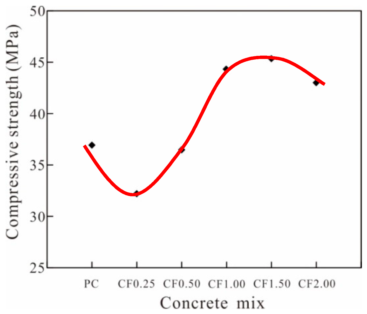
3.2. Effect of Carbon Fiber Content on Compressive Strength

With the increase of freeze-thaw cycles, the mechanical properties will decrease, in which the compressive strength [8] is the most representative indicator. Before discussion of the relation of carbon fiber content and the frost resistance for the concrete, the effect of carbon fiber on compressive strength should be considered. Thus, compressive strength tests of the concrete were conducted at room temperature (Figure 3). The effect of the carbon fiber amount on the compressive strength of the concrete is shown in Table 4 and Figure 4. The PC yielded a compressive strength of 36.9 MPa. The CFRC with a carbon fiber content of 0.25 wt.‰ (0.6 kg/m3) exhibited the lowest compressive strength of 32.5 MPa. When the carbon fiber content was 0.50 wt.‰, the compressive strength of the CFRC was slightly lower than that of the PC. The compressive strength of the CFRC with a carbon fiber content of 1.00 wt.‰ was 37.9 MPa, which was 1.03 times that of the PC. The CFRC with a carbon fiber content of 1.50 wt.‰ had the highest compressive strength of 41.0 MPa. However, the CRFC with a fiber content of 2.00 wt.‰ did not show any improvement in the compressive strength compared with that of CF1.50. Hence, the results showed that when a small amount of carbon fiber was added, the compressive strength of the CFRC was lower than that of the PC, and when the carbon fiber content was more than 1.00 wt.‰, the compressive strength of the CFRC was higher than that of the PC. Thus, the optimal addition amount was 1.5 wt.‰ (3.6 kg/m3).
The compressive strength trend, which shows a decrease at first and then an increase with the increasing of carbon fiber, has a close relationship with the development of cracks in the concrete. Cement agglutinate is mainly comprised of calcium silicate hydrate gel, micropores, and unhydrated cement particles. Micropores include gel pores and capillary pores. Powers [18] proposed a formula for the compressive strength and gel-space ratio: F = AX2.5–3, where F is the compressive strength of concrete, A is the compressive strength of concrete gel, which is in the range of 200–300 MPa, and X is the gel-space ratio, which represents the ratio of the hardened cement volume to the capillary pore volume. The capillary pore appearing in the form of a microcrack is one of the key factors affecting the physical properties of the concrete. Although there are several types of microcracks in the concrete, these can be classified into two types based on the age of the concrete [6]. The first type is plastic shrinkage cracks, and the second type is cracks formed in the concrete hardening stage. Carbon fibers have a greater influence on the first type than the second type [6]. Before hardening, i.e., the plastic deformation stage, the concrete has a small tensile strength. When it enters the constraint state in which internal moisture evaporation is accelerated, many cracks are produced in the interior of the concrete. The fiber reinforcement mechanism on the concrete is mainly the improvement of the crack resistance [19,20,21]. A large number of fibers would be evenly distributed in the concrete as the fine reinforcement, which could effectively share the tensile stress of the concrete resulting from the deformation, and it could also effectively constrain the shrinkage of the concrete and reduce the number and scale of the cracks in the concrete, thus improving the performance of the concrete in all aspects [22,23,24].
However, fibers induce interface defects into the composite material, and these defects have a harmful impact on the mechanical properties of concrete [2]. The influence of fibers on the crack propagation in concrete is controlled by factors such as the fiber amount, fiber distance, drawing strength, interfacial bonds between the fiber and the matrix material, and the strength of the matrix [25,26]. Of these, the interfacial bonding between the fibers and the cement matrix is the most important influencing factor [25,26]. Carbon fibers, as a kind of ductile material, are combined to a concrete matrix by mainly bond forces. Given that stress is transmitted through the interfacial transition zone (ITZ) between the fibers and the matrix, the structure and properties of the ITZ are the key points that determine the performance of a CFRC. According to the research of Powers [18], the increase in the solid volume caused by cement hydration is about 1.13, and the pore around the fiber is about 2.5 times that of the cement matrix. Thus, the ITZ near a fiber surface will have a high porosity, lower hardness, low strength, and more defects [27,28,29,30]. When the fiber content is increased, the induction of cracks by the ITZ will be more evident, which will lead to a reduction in the reinforcement effect of the fibers on the concrete, and even a negative effect can appear [31,32,33]. As long as the fiber orientation is inconsistent with the direction of the principal stress, cracks will be induced, thus affecting the overall mechanical behavior of the concrete [34,35,36].
As shown in this study, at first the fiber content was not sufficient to resist plastic shrinkage, and more weak planes were introduced into the concrete, so the compressive strength of CFRC was reduced. When the carbon fiber content increased, a large number of plastic deformation cracks that formed in the concrete were eliminated, and the positive effect was greater than the introduced weak area. Moreover, the effect of preventing and bridging makes the compressive strength of the concrete increase rapidly, showing an approximately linear strength growth. With the increase in the fiber content, the pores and weak plane reduced the strength significantly. As a result, the compressive strength stopped increasing and even declined.

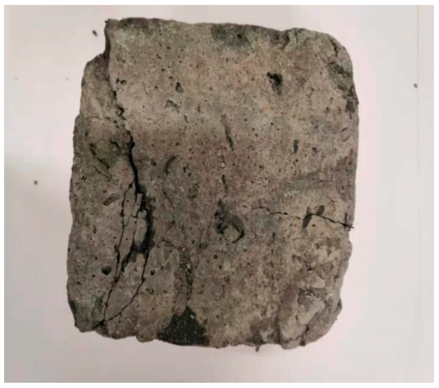
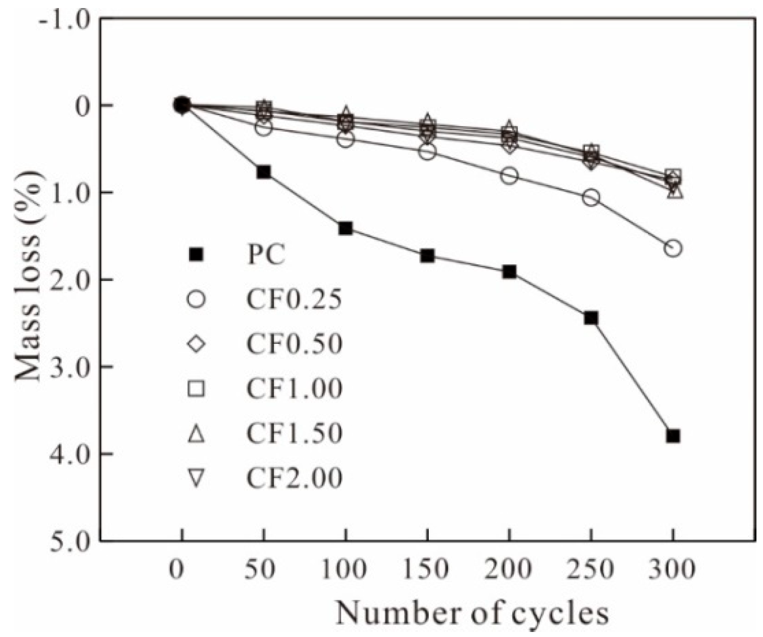
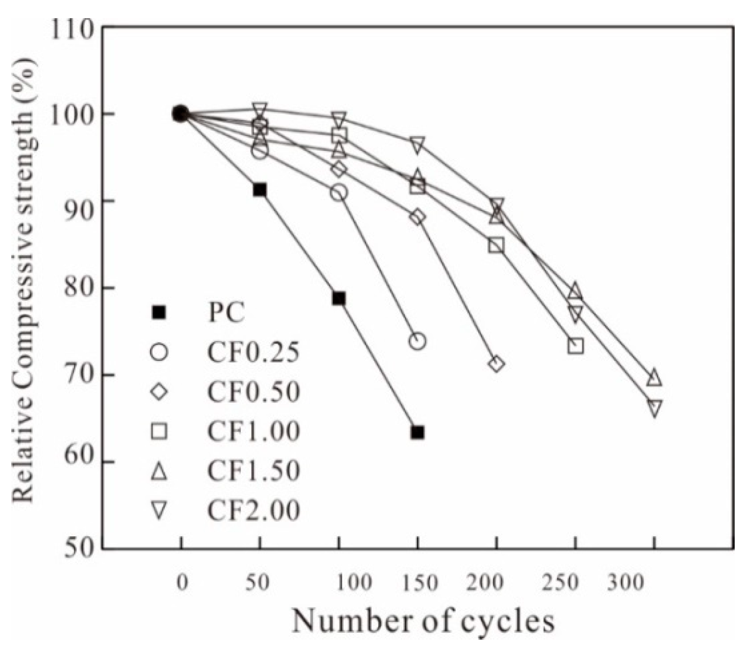
3.3. Frost Resistance of CFRC

In the frost resistance tests, the effects of the fiber content on the mass loss ratio and the compressive strength are shown in Table 5 and Table 6 and Figure 5 and Figure 6, respectively. The PC showed a maximum mass loss of 3.79% after 300 cycles. Before 100 cycles, the PC displayed a moderate mass loss. Between 100 and 250 cycles, the PC displayed a slow mass loss. In contrast, after 250 cycles, the PC displayed a significant mass loss. The CF0.25 yielded a moderate mass loss at 1.64% after 300 cycles. As shown in Figure 5 and Table 5, after 300 cycles, the mass losses of CF0.50, CF1.00, CF1.50, and CF2.0 were 0.98%, 0.82%, 0.86%, and 0.93%, respectively. When the carbon fiber content was greater than 0.5 wt.‰, the mass loss of the CFRC decreased significantly, but the decreases were less than 1%. However, when the carbon fiber content was greater than 0.5 wt.‰, the mass loss of the CFRC did not change significantly with the increase in the fiber amount.
Figure 6 shows that the compressive strength of PC decreases with the number of freeze–thaw cycles. After 150 cycles, the decline of the PC compressive strength was 36.6%. According to GB/T 50082-2009 [14], the frost-resistance mark of the concrete should be based on the maximum number of freeze–thaw cycles after which the compressive strength loss rate was not greater than 25% or the mass loss rate was not greater than 5%. Therefore, the frost-resistance mark of the PC was 100 freeze–thaw cycles, after which the compressive strength loss was 21.2%. After 100 and 150 cycles, the compressive strength values of the CF0.25 declined by 9.0% and 26.1%, respectively. The frost-resistance mark of the CF0.25 was also 100 freeze–thaw cycles, but the degree of decrease of the compressive strength was significantly less than that of the PC. For the CF0.50, the frost-resistance mark was improved to 150 cycles, and the strength loss was 11.8%. The strength losses of the PC, CF0.25, and CF0.50 showed steep declines after the maximum number of freeze–thaw cycles. The CF1.00, CF1.50, and CF2.00 showed high frost resistance performances with frost-resistance marks of 200, 250, and 250 cycles, respectively. After 200 and 250 cycles, the compressive strengths of the CF1.00 were 85.0% and 73.3%, respectively. After 250 cycles, the strength losses of the CF1.50 and CF2.00 were 20.2% and 22.8%, respectively.
Generally, the frost-resistance mark of concrete exhibited an increasing trend with the increase in the carbon fiber content before 1.5 wt.‰. When the carbon fiber content was greater than 1.5 wt.‰, the frost resistance of concrete did not improve further. When the water in pores suffered from frost, its volume swelled by about 9%, which would cause tensile stress and the formation of microcracks [2]. Therefore, the compressive strengths of the concrete showed decreases with the increase in the number of freeze–thaw cycles [2]. The improvement in the frost resistance of the carbon-fiber-reinforced concrete can be explained as the tensile resistance of the fibers that shared the stress of the cement matrix and prevented the formation of cracks. Therefore, the appropriate addition of carbon fibers can improve the frost resistance of concrete. Based on the cost, 1.50 wt.‰ is an optimal carbon fiber addition.

4. Conclusions

This study investigated the effect of carbon fiber on the frost resistance of CFRCs. The following conclusions and inferences can be drawn from this study:
  • The slump of the concrete decreased from 188 to 140 mm with increasing carbon fiber content from 0 to 2.00 wt.‰, showing a decreased trend of workability.
  • The addition of carbon fiber into concrete could decrease the compressive strength first and then cause it to increase, yielding the highest compressive strength of 40.1 MPa with a carbon fiber content of 1.50 wt.‰, which was 1.11 times that of the PC.
  • The addition of carbon fibers could decrease the mass loss of the CFRC significantly. The frost-resistance mark of the CFRC could reach 250 freeze–thaw cycles for carbon fiber contents of 1.50 and 2.00 wt.‰, with corresponding strength losses of 20.2% and 22.8% after 250 cycles, respectively.

Author Contributions

Conceptualization by W.K. and Z.Y.; investigation by W.K.; formal analysis by W.K. and L.Y.; writing, review and editing were performed by all authors; and funding acquisition by W.K. and Z.Y. All authors have read and agreed to the published version of the manuscript.

Funding

This paper is funded by National Key R&D Program of China (2021YFC3100700) and Program for Innovative Research Team in China Earthquake Administration.

Institutional Review Board Statement

Not applicable.

Informed Consent Statement

Not applicable.

Data Availability Statement

Not applicable.

Acknowledgments

We thank Menghan Sun for its linguistic assistance during the preparation of this manuscript.

Conflicts of Interest

The authors declare that they have no known competing financial interest or personal relationship that could have appeared to influence the work reported in this paper.

References

  1. Flores Medina, N.; Barbero-Barrera, M.M. Mechanical and physical enhancement of gypsum composites through a synergic work of polypropylene fiber and recycled isostatic graphite filler. Constr. Build. Mater. 2017, 131, 165–177. [Google Scholar] [CrossRef]
  2. Cao, Q.; Gao, Q.; Gao, R.; Jia, J. Chloride penetration resistance and frost resistance of fiber reinforced expansive self-consolidating concrete. Constr. Build. Mater. 2018, 158, 719–727. [Google Scholar] [CrossRef]
  3. Karahan, O.; Atis, C.D. The durability properties of polypropylene fiber reinforced fly ash concrete. Mater. Des. 2011, 32, 1044–1049. [Google Scholar] [CrossRef]
  4. Yu, H.F.; Sun, W.; Zhang, Y.S.; Huang, D.S. Effect of expansive agent, fiber or their combination on freezing-thawing durability of high performance concrete. Nanjing Univ. Aeronaut. Astronaut. 2006, 38, 245–250. (In Chinese) [Google Scholar]
  5. Rai, A.; Joshi, Y.P. Applications and properties of fibre reinforced concrete. Int. J. Eng. Res. Ind. Appl. 2014, 4, 123–131. [Google Scholar]
  6. Al-lami, K.A. Experimental Investigation of Fiber Reinforced Concrete Beams. Master’s Thesis, Portland State University, Portland, OR, USA, 2015. [Google Scholar]
  7. Horňáková, M.; Lehner, P. Analysis of Measured Parameters in Relation to the Amount of Fibre in Lightweight Red CeramicWaste Aggregate Concrete. Mathematics 2022, 10, 229. [Google Scholar] [CrossRef]
  8. Zaid, O.; Mukhtar, F.M.; M-García, R.; Sherbiny, M.G.E.; Mohamed, A.M. Characteristics of high-performance steel fiber reinforced recycled aggregate concrete utilizing mineral filler. Case Stud. Constr. Mater. 2022, 16, 1–19. [Google Scholar] [CrossRef]
  9. Xiong, B.; Wang, Z.; Wang, C.; Xiong, Y.; Cai, C. Effects of short carbon fiber content on microstructure and mechanical property of short carbon fiber reinforced Nb/Nb5Si3 composites. Intermetallics 2019, 106, 59–64. [Google Scholar] [CrossRef]
  10. Hannant, P.J. Fibre Cements and Fibre Concretes; Wiley: New York, NY, USA, 1978. [Google Scholar]
  11. Mastali, M.; Dalvand, A.; Sattarifard, A. The impact resistance and mechanical properties of the reinforced self-compacting concrete incorporating recycled CFRP fiber with different lengths and dosages. Compos. B Eng. 2017, 112, 74–92. [Google Scholar] [CrossRef]
  12. Deng, Z. The fracture and fatigue performance in flexure of carbon fiber reinforced concrete. Cem. Concr. Compos. 2005, 27, 131–140. [Google Scholar] [CrossRef]
  13. Guo, Z.; Zhuang, C.; Li, Z.; Chen, Y. Mechanical properties of carbon fiber reinforced concrete (CFRC) after exposure to high temperatures. Compos. Struct. 2021, 256, 113072. [Google Scholar] [CrossRef]
  14. GB/T 50082-2009; Standard for Test Methods of Long-Term Performance and Durability of Ordinary Concrete. Chinese Planning Press: Beijing, China, 2009.
  15. GB/T 50081-2019; Standard for Test Methods of Concrete Physical and Mechanical Properties. Chinese Planning Press: Beijing, China, 2019.
  16. Iyer, P.; Kenno, S.Y.; Das, S. Mechanical properties of fiber-reinforced concrete made with basalt filament fibers. J. Mater. Civ. Eng. 2015, 27, 04015015. [Google Scholar] [CrossRef]
  17. GB/T50080-2016; Standard for Evaluation of Concrete Compressive Strength. Chinese Planning Press: Beijing, China, 2016.
  18. Powers, T.C. Physical properties of cement paste. In Chemistry of Cement: Proceedings of the Fourth International Symposium; U.S. Department of Commerce, National Bureau of Standards: Washington, DC, USA, 1960; pp. 577–613. [Google Scholar]
  19. Qian, C.; Stroeven, P. Fracture properties of concrete reinforced with steel–polypropylene hybrid fibres. Cem. Concr. Compos. 2000, 22, 343–351. [Google Scholar] [CrossRef]
  20. Wu, Z.; Shi, C.; He, W. Comparative study on flexural properties of ultra-high performance concrete with supplementary cementitious materials under different curing regimes. Constr. Build. Mater. 2017, 136, 307–313. [Google Scholar] [CrossRef] [Green Version]
  21. Abid, M.; Hou, X.; Zheng, W.; Waqar, G.Q. Mechanical properties of steel fiber-reinforced reactive powder concrete at high temperature and after cooling. Procedia Eng. 2017, 210, 597–604. [Google Scholar] [CrossRef]
  22. Bencardino, F.; Rizzuti, L.; Spadea, G.; Swamy, R.N. Experimental evaluation of fiber reinforced concrete fracture properties. Compos. B Eng. 2010, 41, 17–24. [Google Scholar] [CrossRef]
  23. Visalvanich, K.; Naaman, A.E. Fracture model for fiber reinforced concrete. J. Am. Concr. Inst. 1983, 80, 128–138. [Google Scholar] [CrossRef]
  24. Wecharatana, M.; Shah, S.P. A model for predicting fracture resistance of fiber reinforced concrete. Cem. Concr. Res. 1983, 13, 819–829. [Google Scholar] [CrossRef]
  25. Tjiptobroto, P.; Hansen, W. Tensile strain hardening and multiple cracking in high-performance cement-based composites containing discontinuous fibers. ACI Mater. J. 1993, 90, 16–25. [Google Scholar]
  26. Stähli, P.; Van Mier, J.G.M. Three-fibre-type hybrid fibre concrete. In Proceedings of the Fifth International Conference on Fracture Mechanics of Concrete and Concrete Structures, Vail, CO, USA, 12–16 April 2004; IA-FraMCoS. pp. 1105–1112. [Google Scholar]
  27. Sadrmomtazi, A.; Fasihi, A. Influence of polypropylene fibers on the performance of nano-SiO2-incorporated mortar. Iran. J. Sci. Technol. Tran. B Eng. 2010, 34, 385–395. [Google Scholar]
  28. Sakulich, A.R.; Li, V.C. Nanoscale characterization of engineered cementitious composites (ECC). Cem. Concr. Res. 2011, 41, 169–175. [Google Scholar] [CrossRef]
  29. Kang, S.H.; Kim, J.J.; Kim, D.J.; Chung, Y.-S. Effect of sand grain size and sand-to-cement ratio on the interfacial bond strength of steel fibers embedded in mortars. Constr. Build. Mater. 2013, 47, 1421–1430. [Google Scholar] [CrossRef]
  30. Lee, S.F.; Jacobsen, S. Study of interfacial microstructure, fracture energy, compressive energy and debonding load of steel fiber-reinforced mortar. Mater. Struct. 2011, 44, 1451–1465. [Google Scholar] [CrossRef] [Green Version]
  31. Sovják, R.; Máca, P.; Imlauf, T. Effect of fibre aspect ratio and fibre volume fraction on the effective fracture energy of ultra-high-performance fibre-reinforced concrete. Acta Polytech. 2016, 56, 319–327. [Google Scholar] [CrossRef]
  32. Sovják, R.; Máca, P.; Imlauf, T. Effect of fibre length on the fracture energy of UHPFRC. Procedia Eng. 2017, 193, 74–79. [Google Scholar] [CrossRef]
  33. Kim, K.-C.; Yang, I.-H.; Joh, C. Effects of single and hybrid steel fiber lengths and fiber contents on the mechanical properties of high-strength fiber-reinforced concrete. Adv. Civ. Eng. 2018, 2018, 1–14. [Google Scholar] [CrossRef] [Green Version]
  34. Kang, S.-T.; Kim, J.-K. Investigation on the flexural behavior of UHPCC considering the effect of fiber orientation distribution. Constr. Build. Mater. 2012, 28, 57–65. [Google Scholar] [CrossRef]
  35. Au, C.; Buyukozturk, O. Effect of fiber orientation and ply mix on fiber reinforced polymer-confined concrete. J. Compos. Constr. 2005, 9, 397–407. [Google Scholar] [CrossRef] [Green Version]
  36. Vincent, T.; Ozbakkaloglu, T. Influence of fiber orientation and specimen end condition on axial compressive behavior of FRP-confined concrete. Constr. Build. Mater. 2013, 47, 814–826. [Google Scholar] [CrossRef]
Figure 1. Carbon fibers.
Applsci 12 03823 g001
Figure 2. JCD-400 type slow freeze–thaw machine.
Applsci 12 03823 g002
Figure 3. Fracture specimen.
Applsci 12 03823 g003
Figure 4. Effect of carbon fiber content on the compressive strength. CF, carbon fiber; PC, plain concrete.
Applsci 12 03823 g004
Figure 5. Mass losses of the carbon-fiber-reinforced concrete (CFRC) after different numbers of freeze–thaw cycles. CF, carbon fiber; PC, plain concrete.
Applsci 12 03823 g005
Figure 6. Effect of carbon fiber content on the compressive strength. CF, carbon fiber; PC, plain concrete.
Applsci 12 03823 g006
Table 1. Physical properties of carbon fibers.
Length (mm)Diameter (mm)Aspect RatioVolume Density (g/cm3)Tensile Strength (MPa)Elongation (%)Tensile Modulus (GPa)Carbon Content (%)
60.0078571.8049002.1230>95
Table 2. Variation of mix design.
Mix No.Material Dosage (kg/m3)
CementFACAWaterCarbon FiberDHRWRDA
PC360530136614402.881.440.72
CF0.2536053013661440.62.881.440.72
CF0.5036053013661441.22.881.440.72
CF1.0036053013661442.42.881.440.72
CF1.5036053013661443.62.881.440.72
CF2.0036053013661444.82.881.440.72
CA, carbon aggregate; CF, carbon fiber; D, dispersant; DA, defoaming agent; FA, fine aggregate; HRWR, high-efficiency water-reducing agent; PC, plain concrete.
Table 3. Slump of the concrete.
SpecimenPCCF0.25CF0.50CF1.00CF1.50CF2.00
Slump (mm)188190168148155140
CF, carbon fiber; PC, plain concrete.
Table 4. Compressive strength of the concretes.
SpecimenCompressive Strength (MPa)
NO. 1NO. 2NO. 3MeanRange
PC37.435.837.636.91.8
CF0.2532.731.833.132.51.3
CF0.5035.934.536.135.51.5
CF1.0036.938.138.737.91.8
CF1.5040.340.642.041.01.7
CF2.0037.740.439.139.12.7
CF, carbon fiber; PC, plain concrete.
Table 5. Mass loss ratio of the concretes in the frost resistance test.
Mass Loss Ratio (%)
F-T Cycles50100150200250300
PC0.761.411.721.912.443.79
CF0.250.250.380.530.811.061.64
CF0.500.080.150.200.260.570.98
CF1.000.050.210.260.330.540.82
CF1.500.110.220.360.460.630.86
CF2.000.050.190.330.410.620.93
CF, carbon fiber; PC, plain concrete; F-T cycles is number of freezing and thaw cycles.
Table 6. Relative compressive strength of the concrete in the frost resistance test.
Relative Compressive Strength (%)
F-T Cycles50100150200250300
PC0.910.790.63
CF0.250.960.910.74
CF0.500.990.940.880.71
CF1.000.990.980.920.850.73
CF1.500.970.960.930.880.80
CF2.001.000.990.960.890.770.66
CF, carbon fiber; PC, plain concrete; F-T cycles is the number of freezing and thaw cycles.
Publisher’s Note: MDPI stays neutral with regard to jurisdictional claims in published maps and institutional affiliations.

