Article

An Intelligent Cluster-Based Routing Scheme in 5G Flying Ad Hoc Networks

1
Department of Computing and Information Systems, School of Engineering and Technology, Sunway University, Petaling Jaya 47500, Malaysia
2
Lee Kong Chian Faculty of Engineering and Science, Universiti Tunku Abdul Rahman (UTAR), Kajang 43200, Malaysia
3
School of Engineering, University of Glasgow, Glasgow G12 8QQ, UK
4
National Advanced IPv6 Centre, Universiti Sains Malaysia, USM, Gelugor 11800, Malaysia
*
Author to whom correspondence should be addressed.
Appl. Sci. 2022, 12(7), 3665; https://doi.org/10.3390/app12073665
Submission received: 20 October 2021 / Revised: 8 February 2022 / Accepted: 9 February 2022 / Published: 6 April 2022

Abstract

:
Flying ad hoc network (FANET) is an application of 5G access network, which consists of unmanned aerial vehicles or flying nodes with scarce resources and high mobility rates. This paper proposes a deep Q-network (DQN)-based vertical routing scheme to select routes with higher residual energy levels and lower mobility rates across network planes (i.e., macro-plane, pico-plane, and femto-plane), which has not been investigated in the literature. The main motivation behind this work is to address frequent link disconnections and network partitions in order to enhance network performance. The 5G access network has a central controller (CC) and distributed controllers (DCs) in different network planes. The proposed scheme is a hybrid approach that allows CC and DCs to exchange information among themselves, and handle global and local information, respectively. The proposed scheme is suitable for highly dynamic ad hoc FANETs, and it enables data communication between UAVs in various applications, such as monitoring and performing surveillance of borders, and targeted-based operations (e.g., object tracking). Vertical routing is performed over a clustered network, in which clusters are formed across different network planes to provide inter-plane and inter-cluster communications. This helps to offload data traffic across different network planes to enhance network lifetime. Compared to the traditional reinforcement learning approach, the proposed DQN-based vertical routing scheme has shown to increase network lifetime by up to 60 % , reduce energy consumption by up to 20 % , and reduce the rate of link breakages by up to 50 % .

1. Introduction

During the past decade, the internet has revolutionized almost all fields and has boosted the tremendous growth of user equipment (UE) and bandwidth-starving applications. By end of 2021, data traffic is expected to increase by eight-fold [1] with the introduction of next-generation bandwidth-starving applications (e.g., augmented reality, virtual reality, and driver-less vehicle), and new services (e.g., smart home, smart healthcare, and smart city).
Therefore, there is a colossal demand for significantly higher network capacity and lower delay to support higher mobility of UEs, leading to the need of the next-generation mobile wireless network, namely, fifth generation (5G). Flying ad hoc network (FANET) is one of the new applications supported by 5G.
5G incorporates new technologies, including massive multiple-input and multiple-output (MIMO), device-to-device (D2D) communication, coordinated multi-point (CoMP), and beamforming, providing new features, such as exploring and exploiting mmWave and underutilized spectrum. These features help to achieve improved spectral efficiency, coordinate different kinds of network cells (e.g., macrocells and small cells (SCs), including picocells and femtocells) for achieving reduced interference, and achieve network virtualization for sharing network-wide resources. These features cater for next-generation network scenarios characterized by ultra-densification, heterogeneous, and high variability, in order to achieve a better quality of service (QoS) of up to 10× higher data rate, up to 1000× lower delay, up to 99.999% higher reliability and availability, up to 100× larger network coverage, and up to 10× longer battery lifetime [2]. As an example of the new technologies, D2D enables neighboring nodes to perform direct communication among themselves without passing through a base station (BS), which can offload traffic from the BS to reduce network congestion while reducing delay and energy consumption.
The rest of this section presents an overview of FANET, 5G, vertical clustering, as well as our contributions and the paper organization. Table 1 presents general notations, and Table 2 presents notations related to routing.

1.1. FANET

In FANETs, a large number of unmanned aerial vehicles (UAVs), which are autonomous, small-sized, and lightweight flying nodes, move at high speed at low or high altitudes in a three-dimensional space. Communication in FANETs is characterized by (a) a large transmission range due to the elevated look angle of UAVs, providing long-range connectivity with UAVs and base stations (BSs), and (b) frequent link disconnections and network partitions due to the high-speed and three-dimensional movement [3]. We consider that all nodes in FANETs are UAVs with different characteristics and different roles, namely, cluster member (CM), cluster head (CH), cluster gateway (CG), and vertical cluster gateway (VCG). UAVs have become increasingly important to support resource starving applications of FANETs in 5G and beyond 5G mobile networks [4]. Examples of use cases are advanced mapping and aerial photography, in which UAVs must satisfy the ever-increasing demands for mobile data communication and ubiquitous connectivity to different kinds of wireless devices [4].
As UAVs are battery-powered with limited residual energy, frequent link disconnections and network partitions cannot be addressed by further increasing the transmission range, which can drain out residual energy. Consequently, network performance degrades, including higher overheads (e.g., clustering and routing overheads, and handover) and lower quality of service (QoS) (e.g., lower throughput and higher end-to-end delay). Therefore, efficient vertical routing is performed over a clustered network to increase network stability. One of the most critical issues of UAVs is how to consume the limited residual energy efficiently. The lifetime of the whole UAV network is highly dependent on the energy consumption of UAVs, which is related to their mobility patterns and data transmission. Although UAVs can be equipped with rechargeable batteries powered by solar energy, fuels, and other sources of energy, UAVs should not frequently return to ground stations to charge their batteries frequently, which can reduce their hovering time considerably. Therefore, efficient routing should be performed to enhance network lifetime [5]. In [6], the challenges of data transmission in FANETs, especially reducing its energy consumption, have been addressed. Nevertheless, the proposed approach focuses on increasing network lifetime, reducing energy consumption, and reducing the rate of link breakages for 5G or beyond.
In FANETs, multiple UAVs cooperate and establish an ad hoc network in a multi-UAV scenario. The presence of a large swarm of UAVs is called a multi-UAV swarm. Using 5G to support a multi-UAV swarm provides three main advantages: network scalability, network stability, and load distribution, for achieving improved QoS. As an example, device-to-device (D2D) communication allows neighboring UAVs to communicate with each other without passing through a BS, which can reduce control message exchange and enable traffic offload from the BS, leading to an increased bandwidth availability at BS [7]. As another example, small cells (SCs) are deployed to cater for local traffic in order to reduce energy consumption [8,9]. The BSs provide backhaul access, and they have the privilege to interact with central controllers (CCs). The CCs are responsible for (a) managing network-wide traffic and changes in network topology due to node mobility and dead nodes as a result of battery drainage, and (b) making intelligent routing decisions based on network-wide policies. Network-wide policies deal with vertical routing (i.e., selecting the most favorable route across different network planes efficiently), whereas local policies deal with vertical clustering across different network planes.

1.2. 5G

5G is the next-generation wireless network (see Figure 1) that provides mobile internet connectivity with promising download and upload speeds, wider coverage, and higher stability. 5G incorporates various types of new technologies (e.g., D2D communication), and coordinates different kinds of network cells (e.g., macrocells and SCs, including picocells and femtocells) to reduce interference [10,11,12,13]. The network is generally segregated into different network planes comprised of different network cells; for instance, a macro-plane consists of macrocells. 5G caters for next-generation network scenarios characterized by ultra-densification whereby there is a large number of active UAVs per unit area generating a massive amount of data, and high heterogeneity whereby there is a diverse range of transmission capabilities among UAVs distributed in different network planes (see Section 3).
One of the key features of 5G is the presence of a CC and distributed controllers (DCs) to support the hybrid approach. The CC manages global information (e.g., the residual energy of a UAV and the network plane in which a UAV resides), and allocates network-wide resources (e.g., channels with spatial reuse). The DC manages local information (e.g., the geographical location, node degree, and relative speed, of a UAV), and allocates local resources (e.g., bandwidth and buffer space). This hybrid approach allows the CC and DCs to exchange the global and local information with each other. The presence of DCs allows control functions to be brought closer to UAVs and local infrastructure, particularly the BSs, leading to a reduced interaction time between UAVs and controllers, and increased throughput performance with higher bandwidth availability at the CC.
Using the new technologies of 5G, particularly D2D, across different kinds of network cells in FANETs reduces congestion level and increases throughput. D2D increases bandwidth availability at BS and can support the deployment of different network cells through spatial reuse of frequency bands.
Our proposed framework enables CC and DCs to manage long-lifetime (i.e., with long expiry due to low dynamicity) and short-lifetime data (i.e., with short expiry due to high dynamicity) in order to reduce end-to-end delay under ultra-densified and highly heterogeneous network scenarios. Frequent link disconnections and network partitions are commonplace in highly dynamic FANETs. The scheme consists of vertical routing over a clustered network. By vertical, we refer to mechanisms that involve different network cells (or network planes). While existing routing schemes for FANETs are only horizontal-based and mainly reduce the average number of hops between the source and destination UAVs [14,15], our proposed framework focuses on vertical routing and supports horizontal routing.
Table 3 presents the brief functions of various network elements, and we explain the detailed working of each network element based on the use-case scenario in Figure 1.

1.3. Vertical Clustering

Vertical clustering segregates UAVs with similar nature or behavior into logical groups across different network cells in order to improve network scalability and cluster stability. While ultra-densification and large transmission range increase network connectivity among UAVs in a cluster, network connectivity among UAVs are affected by high heterogeneity and dynamicity. Traditionally, a cluster is comprised of cluster head (CH), cluster member (CM), and cluster gateway (CG) as explained in Table 3. The CH, which serves as the cluster leader, manages and handles cluster-level operations (e.g., routing), and performs intra- and inter-cluster communications. The CM, which is associated with a CH, performs intra-cluster communication. The CG, which is associated with a CH, interacts with neighboring clusters in inter-cluster communication. In vertical clustering, vertical cluster gateway (VCG) is introduced to enable interaction among UAVs in different clusters across different network planes, which is conveniently known as inter-plane communication. In Figure 1, a cluster C 1 , 1 is formed across different network planes (i.e., macro-plane and pico-plane). In this paper, DCs use long-lifetime (e.g., transmission range) and short-lifetime (e.g., geographical location) data to perform vertical clustering, which is a local task to form inter-plane clusters, in order to enhance cluster stability and network scalability. Meanwhile, existing clustering schemes improve cluster stability, which helps in enhancing load balancing, social awareness, fairness, and QoS over a single network plane in 5G networks [2].
Vertical routing enables UAVs to collaborate and coordinate among themselves to establish routes across different network planes, which helps to offload traffic from macrocell to SCs, including picocell and femtocell. In this paper, the CC uses long-lifetime (i.e., residual energy) and short-lifetime (i.e., mobility) data received from DCs to perform vertical routing by selecting next-hop UAVs with lower mobility and higher residual energy in order to increase the network lifetime.

1.4. Our Contributions

Our contributions are as follows:
  • A hybrid framework that enables CC and DCs to handles long- and short-lifetime data, which represents the freshness (or recency) of data, in order to ensure the availability of unexpired data for the local task (i.e., vertical clustering) and the global task (i.e., vertical routing performed over a clustered network) in FANETs under 5G network scenarios.
  • A DQN-based vertical routing over a clustered FANET that selects routes across different network planes (or network cells) to enable inter- and intra-plane communications while improving network lifetime, as well as reducing energy consumption and link breakages. Our proposed scheme focuses on route selection, rather than signaling protocol and message structure, in 5G access networks.

1.5. Paper Organization

Table 4 summarizes the organization of this paper. Section 1 presents the introduction of FANETs, the 5G access network, and the structure of vertical clustering in 5G-based FANET. Furthermore, this section contains the distinguishing aspects of our research and contributions. Section 2 presents the core elements of the 5G access network (i.e., network planes and controllers) and their functions, and the hybrid framework and its advantages. This section also explains the categories of data based on their lifetime, and the significance of fresh data. Section 3 presents the traditional clustering scheme, DQN-based vertical routing, cluster maintenance, the three main components of DQN, the DQN algorithm, and the reinforcement learning algorithm. Section 4 presents research implementation, baseline approaches, ranges of important parameters, energy models, the selection of various performance measures, the analysis of RL and DQN approaches based on learning rate, convergence, simulation results, and complexity analysis. Section 5 presents the significant research outcomes. Section 6 presents future research directions.

2. Related Work

The diverse range of FANET applications has prompted the need to investigate clustering and routing schemes under different mobility models [16], particularly collective motion [17] and random distributive motion [18]. The collective motion enables surveillance [19] in search and rescue missions [20], whereby a group of UAVs gather at a target location [21]. The random distributive motion models a multi-UAV swarm in an area for different purposes, such as collecting data from cellular users, transferring images and videos from a post-disaster area to BSs [22], and deploying an emergency network for recovering communication rapidly in a catastrophic area [23]. Meanwhile, the three-dimensional predictable distributive motion, which is investigated in this paper, is another mobility model in which UAVs move in randomly and uniformly distributed directions and velocities.
Investigations have been made to investigate clustering and routing in FANETs. Clustering algorithms have been proposed to facilitate collaboration among UAVs and network stability, and an extensive survey of clustering, covering features, characteristics, competitive advantages, and limitations, can be found in [24]. Various routing algorithms have been proposed to increase network lifetime, and reduce energy consumption and the rate of link breakages. The routing algorithms can be classified into topology-based, position-based, hierarchical, deterministic, stochastic, and social network-based routing schemes [25].
Clustering and routing in FANETs must address the challenges of high mobility and limited residual energy while providing real-time communication between UAVs and ground control stations. Various tools have been applied to address the challenges of FANETs. In a network with high mobility, ensuring the link stability of a route helps to achieve network-wide stability, leading to improved network performances, such as a higher packet delivery ratio and a lower end-to-end delay. Game theory has been proposed for modeling and analyzing network problems [26]. Machine learning approaches have been proposed. In [27], dueling DQN is applied for managing the mobility of UAVs and planning flight path in a real-time manner while considering both delay and energy consumption requirements in dynamic Internet of things (IoT) sensor networks [28]. In [29], particle swarm optimization (PSO) is applied, and it is based on (a) the bounding box method to address the limited boundary of an area of investigation, and (b) the particle fitness function that takes account of inter-cluster distance, intra-cluster distance, residual energy, and geographic location when selecting CHs while achieving energy efficiency. In [30,31,32], swarm intelligence is used in clustering to achieve scalability.
Algorithm 1: The DQN algorithm.
Complexity
Computational Message Storage
    Input: Sequence of state s 1 i = { m 1 i , e 1 i }
    Output: Action a t i
1: procedure
2:   Initialize experience replay memory R m e m
3:   Initialize main network parameter θ
4:   for  e p i s o d e = 1 : Z  do
5:      Initialize a sequence of state s 1 i = { m 1 i , e 1 i }
6:      for  t = 1 : T  do
7:           Select action a t i = random , if ε a t i , * = max a Q * ( s t i , a t i ; θ ) , if otherwise O C
8:           Execute action a t by using the policy μ θ ( s t , a t ) O ( S A )
9:           Observe state s t + 1 i and delayed reward r t ( s t i , a t i , s t + 1 i ) J
10:           Store experience ( s t i , a t i , r t i , s t + 1 i ) in R m e m O ( S A H n )
11:           Randomly select mini batch of N experiences from R m e m
12:          for  j = 1 : N  do
13:              Set target y j = r j , if terminal s j + 1 r j + γ max a ( s j + 1 , a j ; θ ¯ ) , if otherwise
14:              Update θ via gradient descent on loss function ( y j Q ( s j , a ; θ ) ) 2 ,
15              Differentiate the loss function with respect to θ i
16              θ i L i ( θ i ) = [ ( y i Q ( s i t , a i t ; θ i ) ) θ i Q ( s i t , a i t ; θ i ) ]
17:              Update θ ¯ = θ after C steps O ( S A C )
18:          end for
19:      end for
20:   end for
21: end procedure
In [30], the gray wolf optimization-based algorithm is applied to reduce localization errors in routing while achieving higher energy efficiency and localization accuracy, and minimizing flip ambiguity in the measurement errors of bounded distance. In [33], genetic algorithm with improved selection, crossover, and variation operators takes account of the bandwidth and stability of links and the residual energy of UAVs, leading to higher throughput and network stability, and a lower delay. In [34], fuzzy logic performs routing in two phases. First, in route discovery, the score of each UAV is calculated based on mobility, residual energy, and stability to (a) select routes with a higher fitness, and lower hops and delay, and (b) prevent the broadcast storm problem in which the flood of control messages to discover new routes is limited. Second, route maintenance. The second minimizes route failure and reconstructs broken routes.
Algorithm 2: The RL algorithm.
Complexity
Computational Message Storage
    Input: State s t i
    Output: Action a t i
1: procedure
2:   Observe current state s t i J
3:   if exploration then
4:      Select a random action a t i
5:   else
6:      Select an action a t i , * = argmax a A Q t i ( s t i , a )
7:    end if
8:    Receive delayed reward r t + 1 i ( s t + 1 i , a t + 1 i )
9:    Update Q-value Q t + 1 i ( s t i , a t i ) using Equation (2)        O ( S A )        1
10: end procedure
Q-learning has been proposed to improve various aspects of routing, including selecting next-hop UAVs and routes, estimating link duration, and adjusting the Hello message interval and link holding time, contributing to improved efficiency and reliability in a highly dynamic FANETs [31]. In [35], Q-learning reduces network delay in network scenarios with high mobility, and it has shown to achieve better routing performance compared to other reinforcement learning approaches. The [36] literature extends routing with collaborative data forwarding for improved link stability. The [37] literature extends routing with the Boltzmann machine, which considers bandwidth, residual energy, and link stability in its routing metric. Nevertheless, Q-learning suffers from the curse of dimensionality, and so deep reinforcement learning (DRL) is investigated in this paper.
Compared to existing schemes [18], this paper uses a DRL approaches called DQN due to its fast learning speed in solving complex problems with high dynamicity and dimensionality (or a large state space). Below is a list of distinguishing and important aspects of this work.
  • We consider a DQN-based vertical routing over a clustered FANET that selects routes across different network planes (or network cells) to enable inter- and intra-plane communications while improving network lifetime, as well as reducing energy consumption and link breakages. Our proposed scheme focuses on route selection in 5G access networks, rather than signaling protocol and message structure which have been investigated in the literature [18]. To the best of our knowledge, in the literature, existing routing schemes for FANETs considers the dynamicity of UAVs only [29], and there is lack of investigation in the context of 5G access networks.
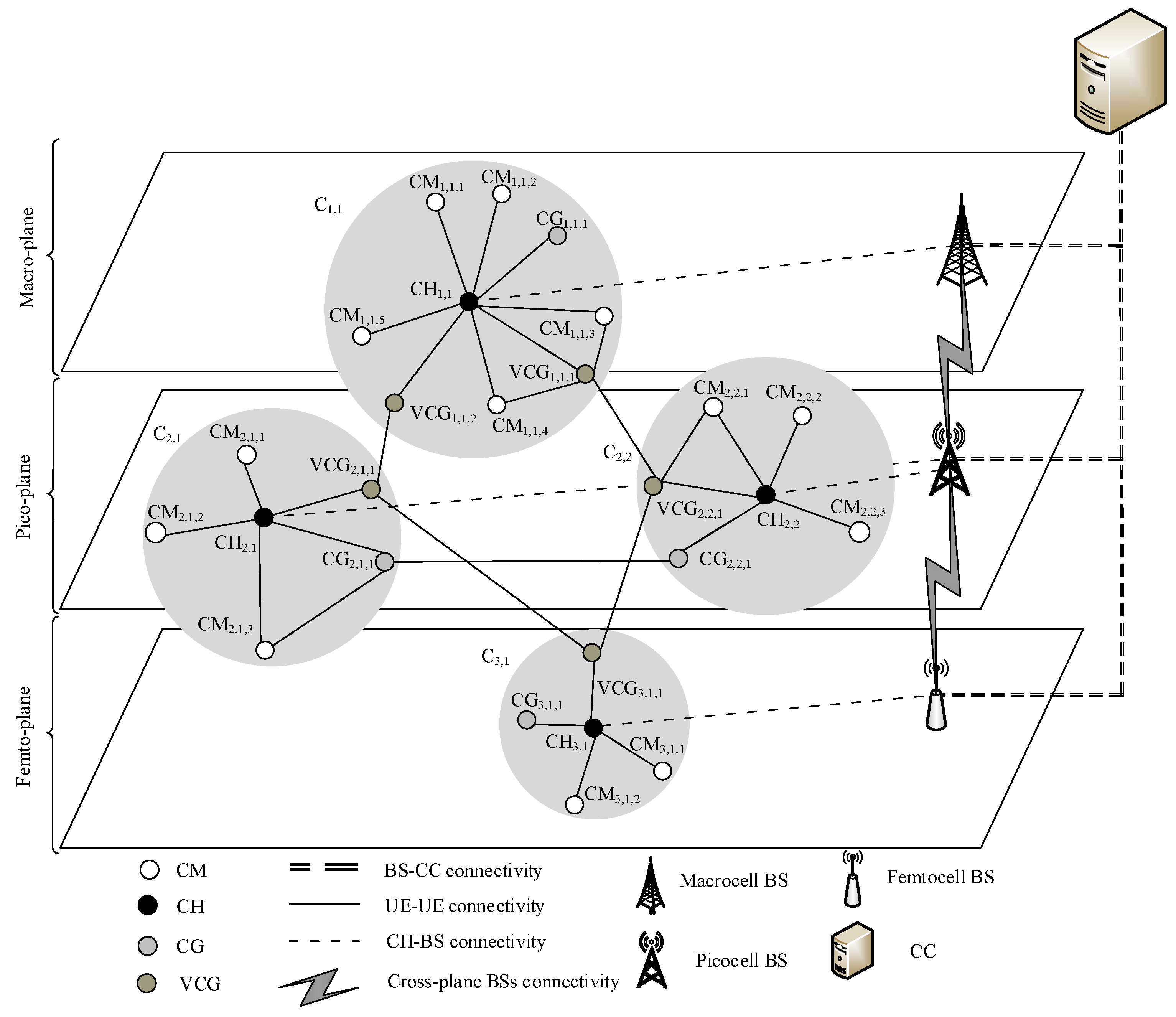
  • We consider inter- and intra-plane communications. Different network planes have different characteristics, and this has not been considered in route selection. Specifically, in 5G access networks, each network plane consists of UAVs and BSs with different characteristics. For instance, macrocells, picocells, and femtocells have large, medium, and small transmission ranges, so they have high, medium, and low node densities of UAVs, respectively. UAVs can switch from one network plane to another (e.g., from the macro-plane to the pico-plane) based on the relative speed of UAVs and the number of handovers across different network planes. The presence of different network cells is unique as compared to traditional access networks which have a single type of network cell. Therefore, the proposed vertical routing scheme over the clustered network involves different network cells (or network planes), while existing routing schemes for FANETs are only horizontal-based and mainly reduce the average number of hops between the source and destination UAVs [14,15]. By considering different network planes, our proposed framework considers both vertical routing across different network planes and horizontal routing within a network plane. To the best of our knowledge, the effect of different network planes to routing has not been considered in the literature.
  • We consider two types of data. Higher dynamicity reduces data lifetime (or freshness) and increases the need to update both CC and DC controllers with new data. Highly dynamic data, such as geographical location, and the moving speed and direction, are generated by UAVs and BSs in FANETs. First, DCs handle the short-lifetime data, which has short expiry due to high dynamicity (i.e., the mobility of UAVs). This data is used for the local task, particularly vertical clustering. Second, CC handles the long-lifetime data has long expiry due to low dynamicity (i.e., residual energy). These data are used for the global task, particularly vertical routing over a clustered network. To the best of our knowledge, the freshness of the data has not been considered in the literature.
  • We use DQN-based routing scheme over a clustered network to manage the highly dynamic network in order to ensure scalability. The main research focus of routing schemes in FANETs is to cater for the dynamicity of UAVs, which causes frequent variations in the network topology. The DQN agent is trained to gain the comprehensive knowledge of the environment in order to improve network lifetime.

3. Network Architecture

Figure 1 shows a 5G network characterized by ultra-densification and heterogeneity. Our investigation focuses on the access network, rather than the network core (or backbone), in which the FANETs and UAVs operate as seen in [2,18]. Due to ultra-densification, a massive amount of data is generated, and due to heterogeneity, UAVs have different transmission capabilities. A 5G network can be segregated into different network planes comprised of different network cells (i.e., macrocell, picocell, and femtocell). There are a CC and DCs. The CC handles the global context, and it (a) gathers global information (i.e., residual energy) and local information (i.e., geographical location) from DCs to provide network-wide information, and (b) sends routing decisions to the DCs, which form routes accordingly. Meanwhile, a DC handles the local context in a network plane, and it (a) gathers global information (i.e., residual energy) from CC, and (b) sends local information and clustering decisions to the CC so that VCGs can be selected for inter- and intra-plane communications.
Network planes. A 5G network consists of three network planes, namely, macrocell, picocell, and femtocell. Each network plane consists of UAVs and BSs with different characteristics as shown in Table 5. In general, the macrocell, picocell, and femtocell have large, medium, and small transmission ranges (or coverage), and so they have high, medium, and low node densities of UAVs, respectively. According to the authors of [38], the macrocell has a coverage of a 1000 m, pico has a coverage up to 100 m, while femto has a coverage of a few meters [38]. UAVs can move from one network plane to another (i.e., either to an upper plane or to a lower plane) based on the relative speed and the number of handovers across different network planes. In order to mitigate the effect of high node mobility, UAVs with high, medium, and low node mobilities connect to macrocell, picocell, and femtocell, in order to reduce handovers among BSs, respectively.
Central controller (CC) makes decisions and manages the global task (i.e., vertical routing). There are three main disadvantages. First, CC causes a lower network scalability. Second, CC causes a lower network reliability due to a single point of failure. Third, CC causes a reduced network performance (e.g., lower throughput and higher end-to-end delay) due to a higher congestion level at the CC [39,40] because it (a) handles a massive amount of data and (b) is updated with highly dynamic data. Therefore, CC may not be suitable to handle FANETs with high node mobility [41]. Distributed controllers (DCs) make decisions and manage local tasks (e.g., in the network plane). Each network plane has a DC that handles UAVs and BSs in the respective plane, and connects the UAVs and BSs to the CC. The DCs handle highly dynamic data, which addresses the disadvantages of the CC. However, the DC has the main disadvantage in which its decisions and management are limited to the local context (i.e., clustering and cluster maintenance).

3.1. Data Lifetime

In FANETs, UAVs and BSs generate highly dynamic data, such as geographical location, and moving speed and direction. Higher dynamicity reduces data lifetime and increases the need to update controllers (i.e., CC and DCs) with the data. Data have either short-lifetime (i.e., with short expiry due to high dynamicity) or long-lifetime (i.e., with long expiry due to low dynamicity) as follows:
t p = long lifetime data , if t p τ short lifetime data , otherwise
where t p and τ represent data lifetime and its threshold, respectively.
Long-lifetime data have a lifetime greater than a predefined threshold t p τ . Therefore, it does not vary frequently and can be updated at least or more than every τ time period. The long-lifetime data resides in the CC; thus, it is also known as the global data available to other UAVs and BSs in the network. In this work, the long-lifetime data is the residual energy of a UAV and the network plane in which a UAV resides.
Short-lifetime data has a lifetime shorter than a predefined threshold t p < τ . So, it varies frequently and changes within every time period τ . The short-lifetime data resides in the DCs in each network plane; therefore, it is also known as the local data available to other UAVs and BSs in the same network plane only. In this work, the short-lifetime data is the mobility rate of UAVs.

3.2. Hybrid Framework

We propose a hybrid framework comprised of CC and DCs. The CC has three main functions. It (a) gathers long-lifetime data and serves as a central data repository to provide a global view of the network, (b) processes global data with high processing capability, and (c) determines network-wide policies and decisions (e.g., policies related to the initialization of the clustering process and vertical routing). The CC provides these functions even when network partitions occur. The DC has three main functions. It (a) gathers short-lifetime data and serves as a local data repository to provide a local view of the network, as well as sends long-lifetime data to the CC; (b) processes local data; and (c) manages the underlying cluster structure. The DCs provide these functions even when CC failure occurs.
The hybrid framework provides three main advantages according to the CAP theorem of distributed computing [42], which is important due to the highly dynamic FANET. First, consistency in which the same short-lifetime data is available to all UAVs and BSs in each network plane, and the same long-lifetime data is available to all UAVs and BSs in the network. Second, availability in which both CC and DCs provide unexpired data to UAVs and BSs in the network. Third, partition tolerance in which the network continues to operate despite the failure of some of the controllers, namely CC and DCs.
In addition, load distribution can be achieved by offloading traffic from CC to DCs, which helps to reduce congestion level at the CC, hence reducing end-to-end delay.

4. System Model and Functions

This section presents the system model and functions, which are based on the traditional clustering and routing mechanisms. Traditional clustering schemes are implemented in a single network plane only without communication across different network planes, and there is lack of a framework to handle long- and short-lifetime data while ensuring the availability of fresh data. However, the vertical clustering scheme forms inter-plane clusters, which are local tasks performed by DCs. DCs use long-lifetime (i.e., transmission range) and short-lifetime (i.e., geographical location) data for vertical clustering in order to enhance cluster stability and network scalability.
Clusters are formed by segregating nodes in the network into groups of nodes with similar nature. For simplicity, only two clusters are shown in Figure 2. Cluster C 1 has a cluster head C H 1 , two cluster members C M 1 , 1 and C M 1 , 2 , and a cluster gateway C G 1 , 1 , and cluster C 2 has a cluster head C H 2 , two cluster members C M 2 , 1 and C M 2 , 2 , and a cluster gateway C G 2 , 1 . Cluster heads C H 1 and C H 2 can communicate with each other in three hops using a route C H 1 C G 1 , 1 C G 2 , 1 C H 2 , whereby links C H 1 C G 1 , 1 and C G 2 , 1 C H 2 are intra-cluster communications and link C G 1 , 1 C G 2 , 1 is an inter-cluster communication. The CHs can also interact with BS. The CM of a cluster cannot communicate with the CG of another cluster directly; and it must communicate via CGs in inter-cluster communication or VCGs in inter-plane communication.
Based on the traditional clustering schemes [2], the underlying clustering scheme in our framework enables the DC of a network plane to gather messages from UAVs periodically in order to form clusters with increased cluster lifetime for ensuring cluster stability. The message contains the three dimensional geographical location, node degree (i.e., the number of neighbors), and mobility metrics of a UAV. The DC selects a UAV with a higher node degree as a CH to increase the CH lifetime. A node with a higher node degree indicates that (a) the mobility of the node and its neighboring nodes is approximately similar, and so it increases connectivity and (b) the node has a larger transmission range. Therefore, the node with a higher node degree is selected as the CH. Using D2D communication, UAVs can communicate with each other in the same cluster, so UAVs can bypass the CHs of their respective clusters via intra-cluster communication. However, D2D communication with nodes from other clusters via inter-cluster communication cannot bypass CHs, which increases the energy consumption of CHs. The DC selects non-clustered UAVs, which are geographically closer to a CH, as the CMs of the CH. The DC selects CGs, which are the CMs with the minimum number of intermediate nodes between two CHs. The DC also selects VCGs, which are the CMs with the highest link expiration time (LET) among the CMs of a cluster, to maintain inter-plane communication.
Cluster maintenance is performed because UAVs have (a) high node mobility with changing coordinates and the relative speed with neighboring UAVs as time passes, (b) high node density (or ultra-densification), and (c) high heterogeneity with different transmission ranges that may overlap. UAVs can switch between network planes (i.e., switches to either an upper or a lower network plane) based on the relative speed and the number of handovers across different network planes. A handover from one network plane to another can increase clustering overhead in both network planes, and so frequent handover is unfavorable. There are two cluster maintenance mechanisms. First, cluster merging combines two clusters to increase the number of CMs in a cluster (or reduce the number of clusters in a network), contributing to a lower number of handovers across different network planes, a lower interference level among the clusters and network planes, and a higher network scalability. Second, cluster splitting divides a single cluster to reduce the number of CMs in a cluster (or increase the number of clusters in a network), contributing to a higher cluster stability.

4.1. Vertical Routing

Vertical routing selects routes with lower mobility in order to prolong route lifetime for improved QoS as network planes have different mobility levels. Network planes with higher mobility levels have lower stability. The UAVs, which have different characteristics (e.g., the coordinates and relative speed vary with time), require vertical routing to (a) coordinate the UAVs in different network planes whereby UAVs have higher mobility levels in macro-plane, followed by pico-plane and femto-plane, and so the femto-plane provides a higher stability, (b) offload data traffic from macro-plane to pico- or femto-plane, and (c) establish routes with higher stability in the network plane. Vertical routing uses VCG, which are selected using LET for increased stability and inter-plane communication.
We present a use case scenario and show how the network entities presented in Table 3 operate. Consider a cluster member C M 2 , 1 , 1 in cluster C 2 , 1 establishes a route to cluster member C M 2 , 2 , 1 in cluster C 2 , 2 in Figure 1. Both UAVs are from the same network plane i = 2 . There are three possible routes: (a) a seven-hop route C M 2 , 1 , 1 C H 2 , 1 V C G 2 , 1 , 1 V C G 1 , 1 , 2 C H 1 , 1 V C G 1 , 1 , 1 V C G 2 , 2 , 1 C M 2 , 2 , 1 with inter-plane communication between network planes i = 2 (i.e., more stable) and i = 1 (i.e., less stable); (b) a five-hop route C M 2 , 1 , 1 C H 2 , 1 C G 2 , 1 , 1 C G 2 , 2 , 1 C H 2 , 2 C M 2 , 2 , 1 with intra-plane communication in network plane i = 2 ; and (c) a five-hop route C M 2 , 1 , 1 C H 2 , 1 V C G 2 , 1 , 1 V C G 3 , 1 , 1 V C G 2 , 2 , 1 C M 2 , 2 , 1 with inter-plane communication between network planes i = 2 (i.e., less stable) and i = 3 (i.e., more stable). As the third route has lower mobility, it is selected to prolong the route lifetime in order to ensure route stability. As an added advantage, the third route provides traffic offload from the macro-plane and pico-plane, which generally have higher congestion level, to femto-plane, which generally has lower congestion level. Nevertheless, the first route may still be chosen to ensure successful data transmission when the rest of the routes have higher mobility rates and lower residual energy levels. In the proposed approach, the UAV with a higher residual energy level and a lower mobility rate is selected as the next-hop node, therefore it is not mandatory to use a route in femto-plane. Nevertheless, the route in femto-plane is preferred as it provides UAVs with lower mobility. Additionally, it helps to off-load data traffic from an upper plane with a higher congestion level to a lower plane with a lower congestion level. There are trade-offs between various network parameters. For example, femto-plane UAVs have comparatively lower residual energy yet offer a higher stability (i.e., a lower mobility rate). On the other hand, femto-plane is less congested which also helps to increase throughput and reduces packet loss.
In our proposed scheme, the decisions of next-hop selection are made in the CC using DQN. There are five reasons in which real-time decisions can be made by nodes, including those carrying real-time data packets, in FANETs with high dynamicity. We segregate these five reasons into two categories, namely the networking aspect and the learning aspect. The networking aspect improves network stability to reduce negative effects to real-time applications as follows:
  • The next-hop selection is performed over a clustered network, which has improved network stability. This is because our proposed vertical clustering scheme selects nodes with higher LET to serve as VCGs for communication among different clusters across different network planes.
  • CHs, which are the distributed entities, make intra-plane decisions to select the next-hop when the source and the destination nodes are from the same network plane. Decisions are made based on the knowledge of the DQN agent. Meanwhile, the DQN agent in CC makes inter-plane decisions to select the next-hop node when the source and the destination nodes are from different network planes. Decisions are based on long-lifetime data (i.e., predictable mobility pattern). Therefore, nodes carrying data can receive forwarding decisions from CHs and CC, while avoiding the delay incurred in receiving forwarding decisions from the CC.
  • UAV nodes increase connectivity among clusters. This is because they UAV nodes have a large transmission range due to their elevated lookup angle.
The learning aspects are as follows:
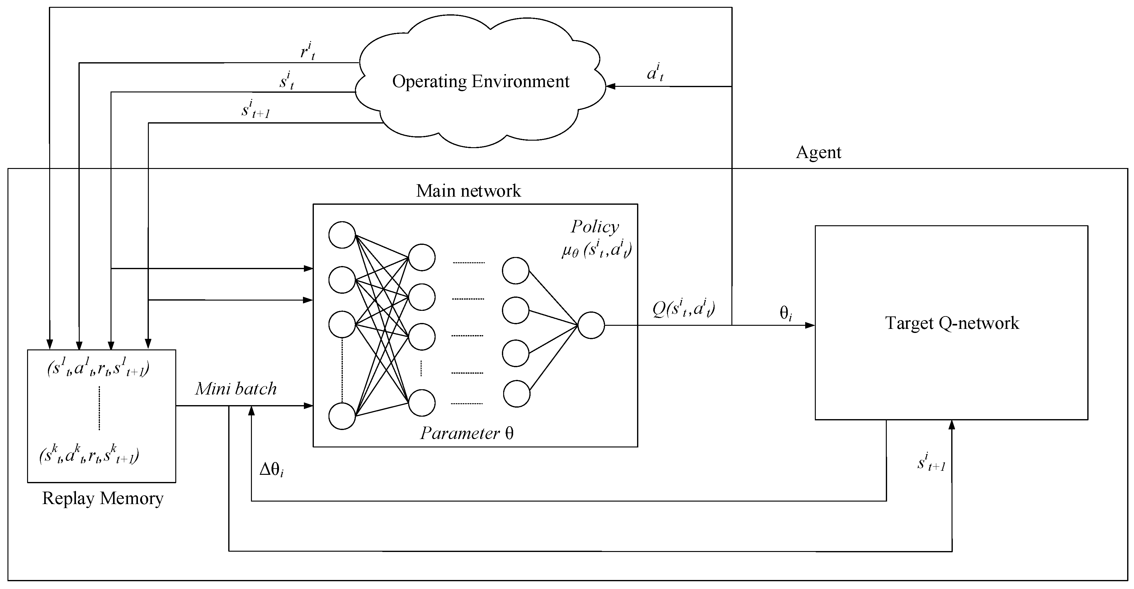
  • The DQN agent embedded in the CC makes decisions based on state-action values, which represents the long-term reward. Specifically, the action with the highest state-action value is selected. By considering the long-term reward, DQN may not change its selection of actions (or policy) after every single variation in the network. This is because the best possible action may remain optimal from the long-term perspective; specifically, it continues to achieve the highest state-action value compared to the rest of the potential actions. Therefore, nodes carrying real-time data can still select optimal action, which is the forwarding decision, based on its state-action values while avoiding the delay incurred in receiving forwarding decisions from the CC.
  • The DQN agent represents two aspects of mobility, namely speed (which is the short-lifetime data) and direction or predictable mobility paths (which is the long-lifetime data), as the state, and so it learns the predictable mobility patterns of UAV nodes. This helps to reduce the rate of link breakages (i.e., disconnectivity) between nodes.

4.2. DQN-Based Vertical Routing Scheme

DQN is embedded in CC (or agent). The CC contains global information and selects a favorable route from a source UAV to a destination UAV based on routing metrics, including the mobility and residual energy of UAVs, in order to prolong route lifetime. Figure 1 depicts the access network. The entities that an agent interacts with are external to the agent, and they are conveniently called the operating environment. In Figure 3, DQN, which is embedded in CC, is applied to the operating environment for improving network lifetime, as well as reducing energy consumption and link breakages.
There are three main representations in an agent. First, state represents the decision making factors. The state of an agent i at time t is s t i = ( m t i , e t i ) S , where m t i M represents mobility, and e t i E r represents the residual energy level. Second, action affects the reward under the state. The action of an agent i at time t is a t i A = { x M , E r h X } , which represents the selection of a next-hop node out of a set of available next-hops nodes X towards the destination node. The next-hop node can be a CH, CM, CG, VCG, or BS. A route cannot be established when there is a lack of an available next-hop, which is considered a link breakage. Third, delay reward represents the performance measures. The delayed reward received by an agent i at time t is r t ( s t i , a t i , s t + 1 i ) = w ( r t i , j ) + ( 1 w ) ( c t i , j ) , where the weight factor is 0 w 1 , and both r t i , j and c t i , j are normalized to [ 0 ,   1 ] . Therefore, the delayed reward has two components: (a) r t i , j represents the successful transmission rate of packets towards the destination from node i to node j at time t when both nodes are moving; and (b) c t i , j represents the network congestion level between nodes i and j. The delayed reward helps a node i to find a stable route to increase the route lifetime and data traffic offload from macro-plane to pico- or femto-plane.
Figure 3 presents an overview of DQN and its composition. DQN is a value function-based approach that estimates the Q-value of its possible actions. A DQN uses a deep neural network (DNN), which is characterized by network parameter (or weight) θ , to approximate an action-value function (or Q function) [43]. In our proposed solution, DQN is embedded in the CC. In addition, DQN has another three important components. First, replay memory is used to store experiences for training DNN. Second, the main network, which is characterized by the main network parameter (or weight) θ , provides Q-values Q ( s i t , a i t ; θ i ) that defines the agent’s policy. Third, the target Q-network, which is characterized by target Q-network parameter (or weight) θ ¯ , provides the target Q-values Q ( s i t , a i t ; θ ¯ i ) used to establish a predefine estimated value for updating network parameter θ while minimizing a loss function.
Algorithm 1 shows the DQN algorithm. At each episode z, an agent i N observes state s t i = ( m t i , e t i ) and feeds it into its DNN (Step 5). The agent i selects either an exploitation or an exploration action using the ε -greedy approach (Step 7). The decaying variable ε d e c a y helps to tend towards exploitation from exploration as episode increases. During exploitation, the agent selects a next-hop node based on the state s t i . During exploration, the agent explores the possible actions. The output Q-value Q ( s t i , a t i ; θ i ) is selected based on policy μ θ ( s t i , a t i ) (Step 8). At the next time instant t + 1 , the agent i in CC observes the next state s t + 1 i , which includes information from DCs, and receives a reward r t ( s t i , a t i , s t + 1 i ) (Step 9). The agent i stores this experience, and so it has experiences { ( s t 1 , a t 1 , r t 1 , s t + 1 1 ) , , ( s t k , a t k , r t k , s t + 1 k ) } up to this time instant stored in the replay memory R m e m (Step 10).
A mini batch of experience samples ( s t l , a t l , r t , s t + 1 l ) are selected randomly from the replay memory R m e m to train the DNN (Step 11). The mini batch of samples has two characteristics: (a) independent because the samples are selected randomly to calculate a desired target function y j (i.e., pre-estimated value for training) (Step 13), which is then used to update the network parameter θ using gradient descent based on a loss function y j Q ( s i t , a i t ; θ ) (Step 14), and (b) stable because real experiences are used to update network parameters. In the gradient descent approach, the loss function is differentiated with respect to θ i using θ i L i ( θ i ) = [ ( y i Q ( s i t , a i t ; θ i ) ) θ i Q ( s i t , a i t ; θ i ) ] , and this process is repeated until it reaches the minimum value of the loss function (Steps 15 and 16). The target network parameters θ ¯ is copied from the main network parameters θ every C steps, specifically θ ¯ = θ (Step 17).
The CC receives short-lifetime data (i.e., neighboring nodes of the source and destination UAVs) from DCs regularly to form a global NS, and establishes a route, which consists of intra- and inter-cluster, as well as intra- and inter-plane communications, between a source UAV and a destination UAV.

4.3. Reinforcement Learning

Reinforcement learning (RL), as shown in Algorithm 2, is also embedded in CC for comparison. At time t, an agent i in CC observes state s t i , which includes information from DCs, and selects a random action a t i (during exploration) or an optimal action a t i , * (during exploitation) as follows (Step 6):
a t i , * = argmax a A Q t i ( s t i , a )
The agent i receives a positive or negative delayed reward r t + 1 i ( s t + 1 i , a t + 1 i ) from the operating environment at the next time instant t + 1 (Step 8). The agent i explores each possible combination of state-action pair to update its Q-values with respect to time t = 1 , 2 , using Equation (2) as follows (Step 9):
Q t + 1 i ( s t i , a t i ) = ( 1 α ) Q t ( s t i , a t i ) + α [ r t + 1 ( s t + 1 ) + γ argmax a Q t ( s t + 1 i , a ) ]
where learning rate is 0 α 1 and discount factor is 0 γ 1 .

5. Performance Evaluation, Results, and Discussion

DQN-based vertical routing scheme, which is embedded in the CC, selects a route with low energy consumption and mobility rate from a source node to a destination node. The proposed scheme reduces energy consumption and the rate of link breakages, and increases network lifetime. Ultimately, it contributes to a higher network stability. The main focus of research on routing schemes in FANETs has been focusing on catering to the dynamicity of UAVs [29]. Swarm intelligence based algorithms have been used for clustering to ensure scalability [30,31]. To the best of our knowledge, there is no routing scheme designed for FANETs in the context of 5G access networks in the literature. 5G access networks contain controllers (i.e., CC and DCs) and network planes (i.e., macro-, pico-, and femto-planes), which are unique compared to traditional access networks. Moreover, the proposed vertical routing approach for multiple network planes in 5G access networks is first of its kind. As there is lack of state-of-the-art vertical routing schemes for comparison with our proposed scheme, the traditional RL, random, and optimal approaches are selected. These approaches are chosen because the optimal approach provides the best possible results, and the random approach provides the worst possible results. The DQN approach is compared with its predecessor, namely, RL, and it is investigated with different learning rates. The learning rate of RL is a hyperparameter that controls how quickly the RL approach adapts to the dynamicity of the operating environment. DQN has shown to outperform RL. Similar to [44], UAVs are deployed following the distributive motion, so we consider three-dimensional predictable motions with uniformly distributed directions and random velocity that after an iteration. The source and destination UAVs are selected randomly [45]. The rest of this section explains our simulation platforms, baseline and optimal approaches, simulation parameters, performance measures, analysis, simulation results and discussions, and complexity analysis.

5.1. Simulation Platforms

Simulation is performed using MATLAB (i.e., version 2019b) [46] and Python (i.e., version 3.6) [47], which are the preferred tools for similar investigations in the literature [48,49]. MATLAB (or matrix laboratory) uses mathematical modeling to develop algorithms, compute large arrays and matrices, as well as accumulate and record statistics. In Python, deep learning is implemented using the Keras library [50] in the TensorFlow framework (i.e., version 1.1). RL algorithms are implemented and compared using the Gym toolkit [47], and the network topology that consists of flying nodes are implemented using the Nx toolkit [51].

5.2. Baseline and Optimal Approaches

Our proposed scheme is compared with two approaches. First, in the random approach, which serves as the baseline approach, an agent i N selects and takes a random action from a set of potential actions (i.e., a set of available next-hop nodes) at all times. The performance of the random approach reduces as network density increases as shown in Section 5.7 when the possibility of selecting the best possible action reduces when more options are available with increased network density. Second, in the optimal approach, an agent i selects and takes the optimal action, which is the UAV with lower mobility (or higher stability) and higher residual energy, at all times. This establishes an optimal path from the source UAV to its destination UAV. The optimal path is selected by considering the node conditions, whereby nodes with higher residual energy and lower mobility are selected as next-hop nodes, contributing to improved network lifetime and stability performances.

5.3. Simulation Parameters

Table 6 shows the simulation parameters and values. The units for performance measures are (a) energy consumption is measured in joule, (b) rate of link breakage is measured in percentage, (c) network lifetime is measured in mili-seconds, (d) node mobility is measured in meter per second, and (e) network density is measured in number of nodes. The values are chosen as they provide the best possible results based on our analysis in Section 5.6.
Network planes are characterized by node density, node mobility, and transmission range. UAVs with different mobile characteristics are associated with different network plane: (a) low-altitude (i.e., ≤400 m) and slow-speed (i.e., 0–33.3 m/s) UAVs are associated with the femto plane; (b) medium-altitude (i.e., 401–1100 m) and medium-speed (i.e., 33.4–67.3 m/s) are associated with the pico-plane; and (c) high-altitude (i.e., 1100–2000 m) and high-speed (i.e., 67.4–100 m/s) are associated with the macro-plane. The transmission ranges of UAVs are 10–100 m in femto-plane, 10–300 m in pico-plane, and 10–500 m in macro-plane.
The size of a batch is 32 and the replay memory is 2000. Only 32 experiences are taken from the replay memory to train DNN in each episode. When the number of entries in the replay memory reaches its capacity of 2000, the de-queue operation is used to remove the earliest experience from the replay memory, and recent experiences are added. The reason for choosing small values of the batch size and the replay memory is to (a) handle a highly dynamic environment because earlier experiences may not be useful as compared to recent experiences, (b) use recent experiences in the replay memory for learning, and (c) use recent experiences to expedite the learning process in run-time training for DNN in a highly dynamic environment.
Each simulation run is performed for 100 iterations, and each iteration has 1000 episodes. After each iteration, the position of UAVs is updated based on mobility. The range of values for network density, node mobility, transmission range, and their distributions in different network planes are shown in Table 5. However, the transmission range is from 10 m to 500 m because some UAVs can transmit data to the entire simulation area, particularly the UAVs in the macro-plane. Our research focuses on vertical clustering and routing. A UAV may send data from a macro-plane to a femto-plane and vice-versa, and intermediate UAVs forward data towards a destination UAV. Similarly, the size of the simulation area is 2 km 3 .
In this research, the τ is set to a single episode z, and so the long-lifetime data does not change within an episode z.

5.4. Energy Model

In UAVs, energy consumption is caused by three mechanisms: (a) the actuating of motor control of a UAV when flying in the air, E m o t o r ; (b) communication between sensors E s e n s o r ; (c) communication among UAVs, and between UAVs and BS, E c o m , which is the major cause of energy consumption in UAVs. The equations for the various kinds of energy consumption are as follows [52,53,54,55].
E = E c o m + E m o t o r + E s e n s o r
E c o m = E T x + E R x
E T x = E e l e c t × L + E a m p × L × d 2
E R x = E e l e c t × L
where E T x and E R x are energy consumption during the transmission and reception of data packets, respectively. E e l e c t is the energy consumed by the transmitter and receiver circuitry, E a m p is the energy consumed by transmit amplifier, L is the number of bits transmitted, and d is the distance between transmitting and receiving nodes.

5.5. Performance Measures

There are three performance measures. Energy consumption represents the average number of energy units (i.e., joule) consumed for a successful transmission of a data packet from a source node to a destination node. Lower energy consumption improves the energy efficiency of a network. Rate of link breakages represents the average percentage of link breakages (out of all link breakages) caused by the drainage of residual energy and UAV movements. Lower number of link breakages indicates a lower route maintenance and a higher cluster stability, leading to lower packet loss and delay. Network lifetime represents the average network failure time when 3 4 of the UAVs in the network run out of residual energy. Higher network lifetime improves throughput. Our simulation is investigated with respect to two aspects: Network density represents the number of nodes in a fixed-size area. Node mobility represents the speed of a node (m/s) ranging from 10 m/s to 100 m/s. In the experiments, the lower limit of 10 m/s is fixed, while the upper limit of 100 m/s may be changed. Our proposed scheme selects routes across different network planes (or network cells) to enable inter- and intra-plane communications while improving network lifetime, as well as reducing energy consumption and link breakages. Our proposed scheme focuses on route selection, rather than signaling protocol and message structure, in 5G access networks. Similar to the investigations in [55,56], packet-based network performance, such as end-to-end packet delivery ratio, are not selected. Our proposed scheme aims to (a) reduce energy consumption which increases the availability of residual energy and (b) reduce the rate of link breakages which reduces the packet drop ratio. Improving these performance measures has shown to increase the end-to-end packet delivery ratio [55,57].
There is a correlation between the performance measures. As node mobility increases, the rate of link breakages increases exponentially as shown in Section 5.7.5. This increases network lifetime as shown in Section 5.7.6 due to the lack of data transmission when new routes are being established and stored in DCs.
In general, DQN provides the best results as compared to the traditional RL and random approaches. Our proposed scheme focuses on route selection choosing the most favorable route with a higher residual energy and a lower mobility, rather than signaling protocols and message structures, in 5G access networks. Therefore, we have chosen to improve performance metrics, including energy consumption, rate of link breakages, and network lifetime. Enhancing these performance metrics improves QoS, such as packet loss rate, throughput, and end-to-end delay as shown in [58,59]. For instance, a lower rate of link breakages improves network stability and lifetime because UAVs can transmit data over their respective routes for a longer time duration without incurring clustering and routing overheads, leading to a lower packet loss rate, a higher throughput and a lower end-to-end delay.

5.6. Analysis

This section presents an analysis of the two main approaches, namely, RL and DQN, via simulation. The analytical outcomes presented in this section help to analyze the effects of various parameters (i.e., learning rate α , exploration rate ε , and decaying variable ε d e c a y ) to the learning capability of RL and DQN [60,61,62]. The best possible parameters are identified, and simulations are performed based on these parameters for performance comparison between RL and DQN. In this research, the τ value is set to a single episode z, and so long-lifetime data does not change within episode z.

5.6.1. RL

Figure 4 and Figure 5 present the analytical results of the RL approach based on the state, action, and reward representations of our model (see Section 4.2).
As the learning rate increases from α = 0.1 to α = 1.0 , energy consumption reduces (see Figure 4a), the rate of link breakages reduces (see Figure 4b), and the network lifetime increases (see Figure 4c) with network density. At learning rate α = 1.0 , energy consumption and the rate of link breakages are the lowest, and the network lifetime is the highest. This is because a higher learning rate enables UAVs to (a) use delayed reward based on recent geographical location of UAVs, which helps to form links between UAVs in a highly dynamic environment in which UAVs are moving at high speed, and (b) select routes with higher residual energy and lower mobility in order to enhance network lifetime.
Similar trend is observed in our investigation with respect to mobility as shown in Figure 5. In Figure 5a, energy consumption increases significantly due to an increased packet re-transmission as a result of packet loss when mobility reaches 80 m/s.

5.6.2. DQN

Figure 6 and Figure 7 present the analytical results of DQN. The state, action, and reward representations of our model are presented in Section 4.2. As the learning rate increases from α = 0.0001 to α = 0.001 , energy consumption reduces (see Figure 6a), the rate of link breakages reduces (see Figure 6b), and the network lifetime increases (see Figure 6c) with network density. At learning rate α = 0.001 , energy consumption and the rate of link breakages are the lowest, and the network lifetime is the highest. This is because a higher learning rate enables UAVs to (a) use delayed reward based on experiences from replay memory R m e m . These experiences ( s t i , a t i , r t i , s t + 1 i ) contain current state values and next state values, which are important to select a favorable route in a dynamic environment. Experiences generated using higher learning rates provide better learning for DNN as compared to experiences generated using lower learning rates because these experiences contain more recent and fresher experiences; (b) use decaying exploration rate ε d e c a y that tends towards exploitation from exploration as the number of episodes increases; and (c) represent the recent angle of arrival as state, which is trained using mini batches from replay memory R m e m , which helps in convergence towards the most favorable route (i.e., the route with a higher residual energy and a lower mobility) in order to enhance network lifetime.
The number of link breakages increases with an increasing network density. A higher network density increases the number of hops, and so it increases the energy consumption of data transmission and reception along a route from a source node to a destination node, resulting in a higher number of link breakages. The number of link breakages decreases with increasing learning rate, which helps to select a route with a higher residual energy and stability. When the learning rate is low, the number of link breakages is high because selected routes have UAVs with low residual energy. For the effects of network density on DQN, the learning rate α = 0.001 achieves the lowest link breakages. Lower link breakages improve the stability and lifetime of a network. There is a correlation between different performance measures. While an increase in network density improves network lifetime exponentially, it degrades network performance due to an increase in the rate of link breakages and energy consumption. This is because a higher network density increases the number of nodes in a route (or the length of a route), which increases the number of possible actions (i.e., the potential next-hop or intermediate nodes), resulting in an increased energy consumption for data transmission and reception.
Similar trend is observed in our investigation with respect to mobility as shown in Figure 7. In Figure 7a, the network lifetime increases because the energy consumption incurred by data transmission and reception reduces due to increased link breakages as the mobility rate increases.

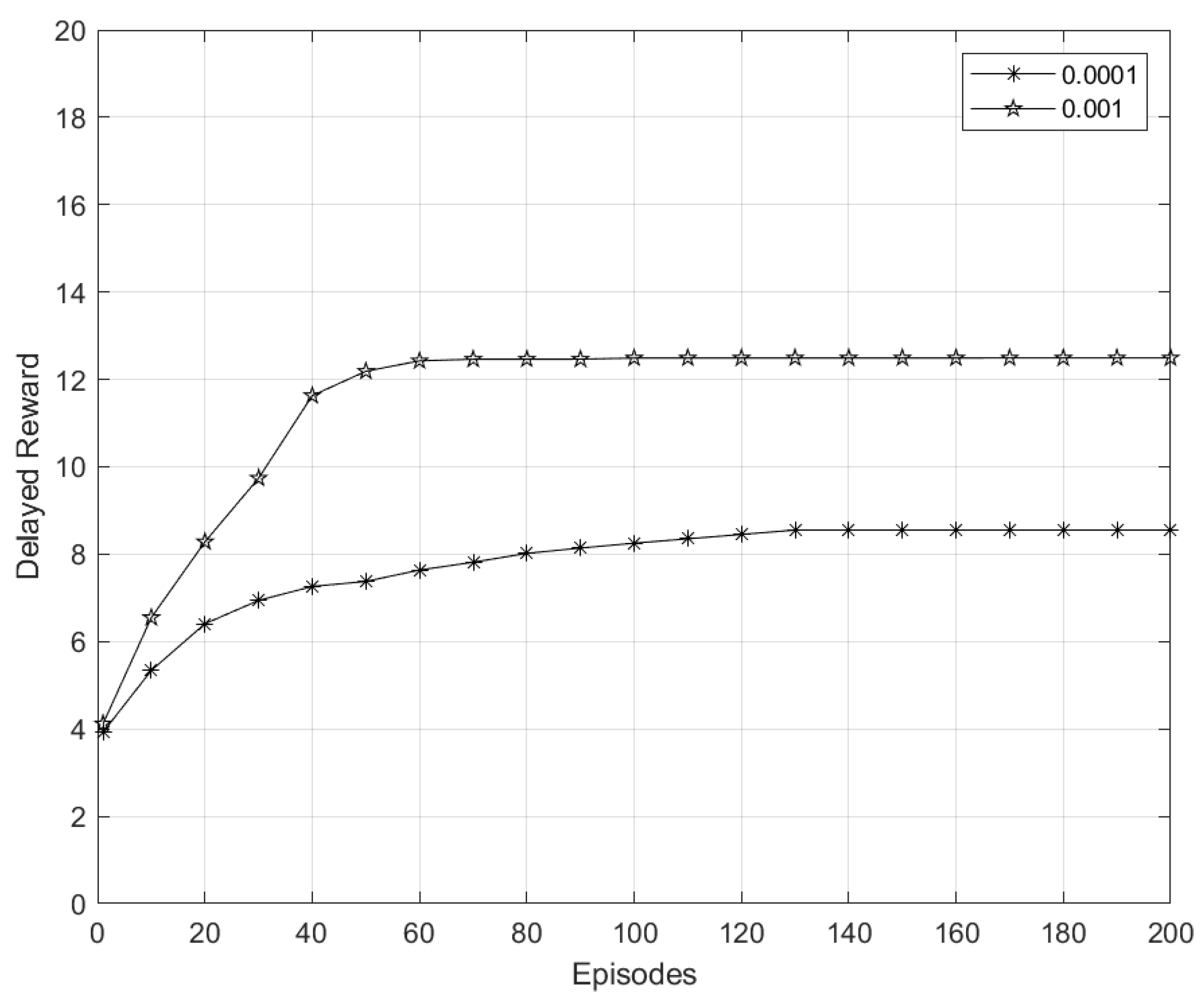
5.6.3. Convergence of DQN Algorithm

Figure 8 shows the delayed reward of DQN. It shows that the delayed reward converges at approximately 12 after almost 60 episodes when the learning rate is α = 0.001 , and the delayed reward converges at approximately 8 after almost 100 episodes when the learning rate is α = 0.0001 . It is worth highlighting that the learning rate α value may vary based on the underlying application scenarios. At the initial episodes, the delayed reward for both learning rates α of DQN is unstable; however, as the episode advances, the delayed reward becomes stable. A higher learning rate α enables an agent i to converge faster. On the other hand, a smaller learning rate α can cause a slower convergence (or a longer training time).

5.7. Simulation Results and Discussions

The simulation results and discussions are as follows.

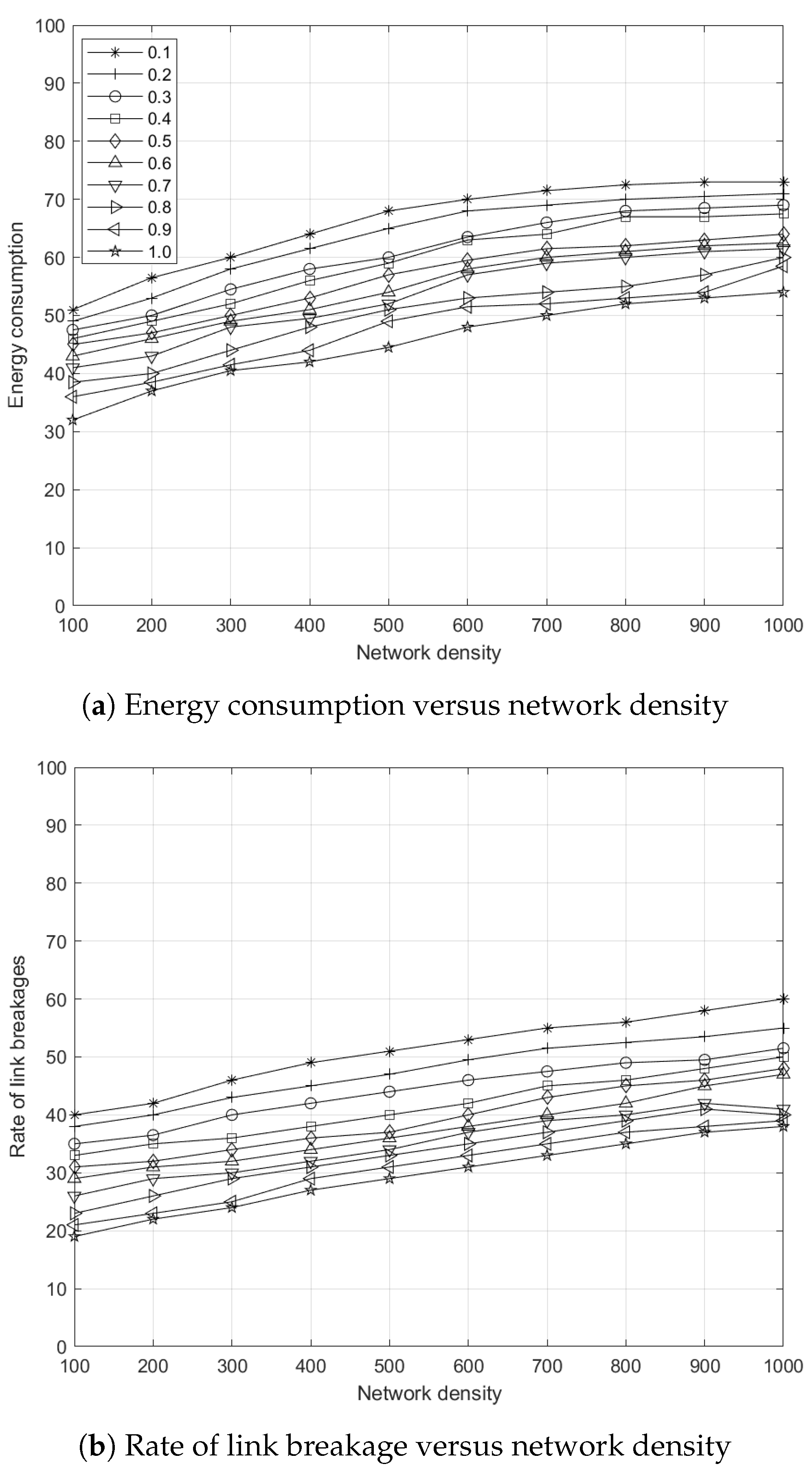
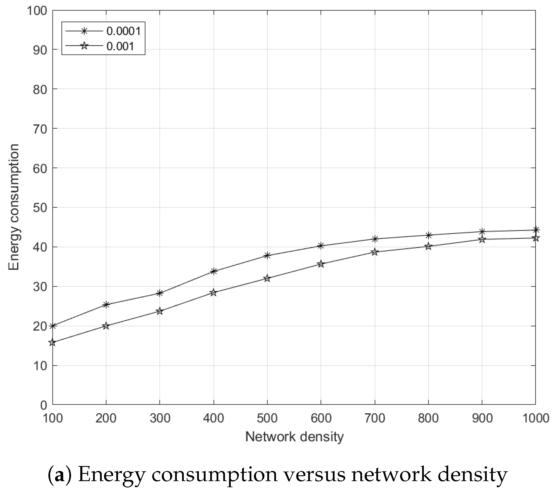
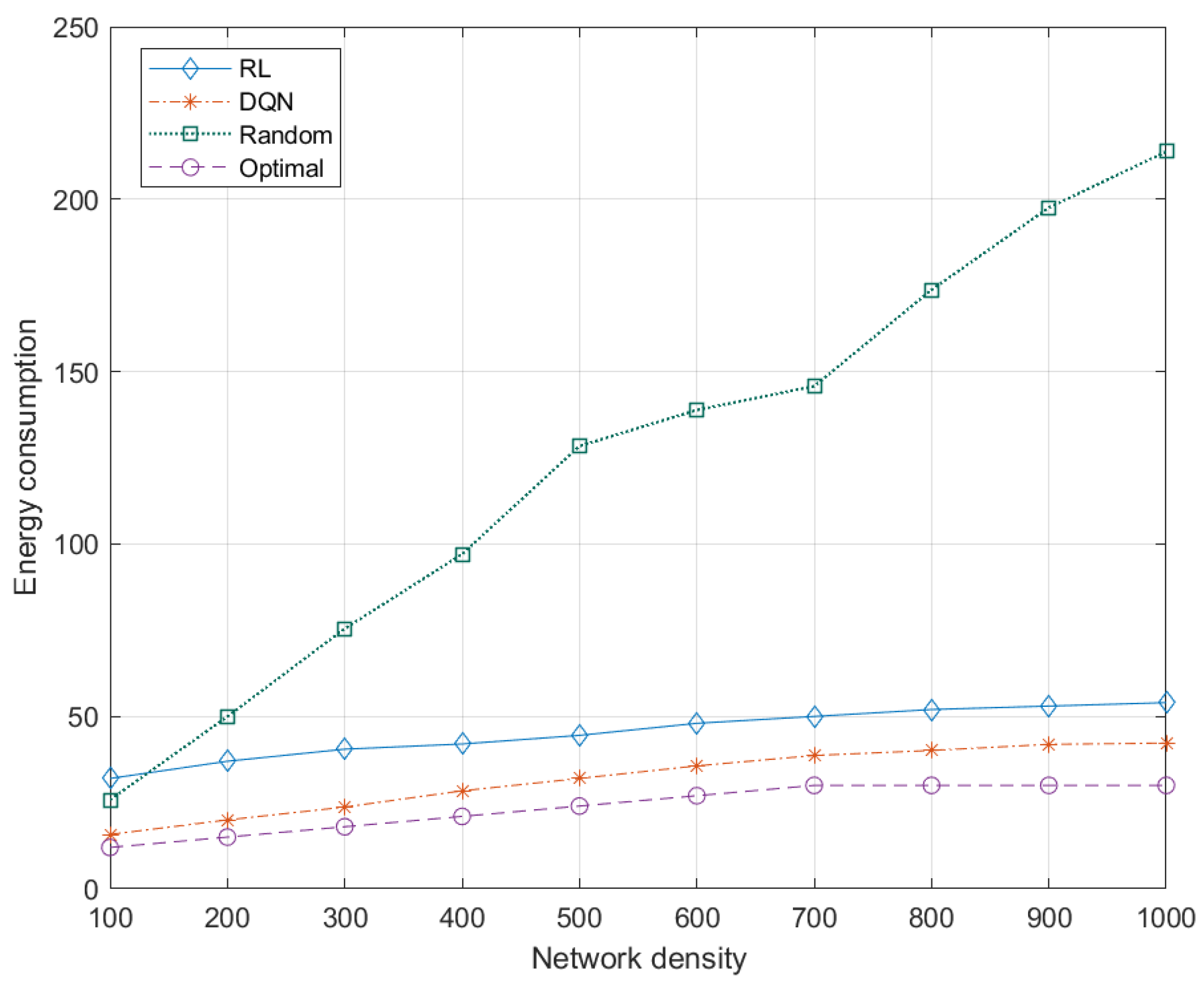
5.7.1. Effects of Network Density to Energy Consumption

The energy consumption of a route (i.e., data transmission from a source UAV to a destination UAV) increases gradually as network density increases as shown in Figure 9.
Energy consumption is based on the energy consumed by an end-to-end route (i.e., from a source node to a destination node). Based on Table 5, there are three assumptions Table 5): (a) the size of data packets is similar, (b) the transmission of a single data packet in each hop consumes two energy units (i.e., joule), and (c) the reception of a single data packet consumes one energy unit. The energy consumption of a route is caused by data transmission from a source UAV to a destination UAV, which increases gradually as network density increases as shown in Figure 9. DQN outperforms RL with at least 20 units lower energy consumption when network density is lower (i.e., 100 UAVs), and at least 15 units lower energy consumption when network density is higher (i.e., 1000 UAVs). For instance, in DQN, the energy consumption of 100 nodes is 15 units, which means there are 5 transmissions and receptions from source to destination UAVs. Similarly, the energy consumption of 1000 nodes is 40 units, which means there are 20 transmissions and receptions of data packet from source to destination UAVs.
DQN outperforms RL with at least 20 units lower energy consumption for lower network density (i.e., 100 UAVs), and at least 15 units lower energy consumption for higher network density (i.e., 1000 UAVs). Therefore, DQN increases network lifetime and network stability. This improvement is attributed to the use of DQN at CC to predict the state-action value of a route based on the availability of residual energy and mobility with respect to the proximity of a destination UAV. Subsequently, DQN converge to the most favorable route, which has a lower energy consumption as time goes by, across various network planes (i.e., macro-, pico-, and femto-planes). Meanwhile, the random approach has higher energy consumption (i.e., more than 200 units) due to its randomness, while the energy consumption of the DQN, RL, and optimal approaches does not vary considerably for most network densities, particularly from 700–1000 nodes.

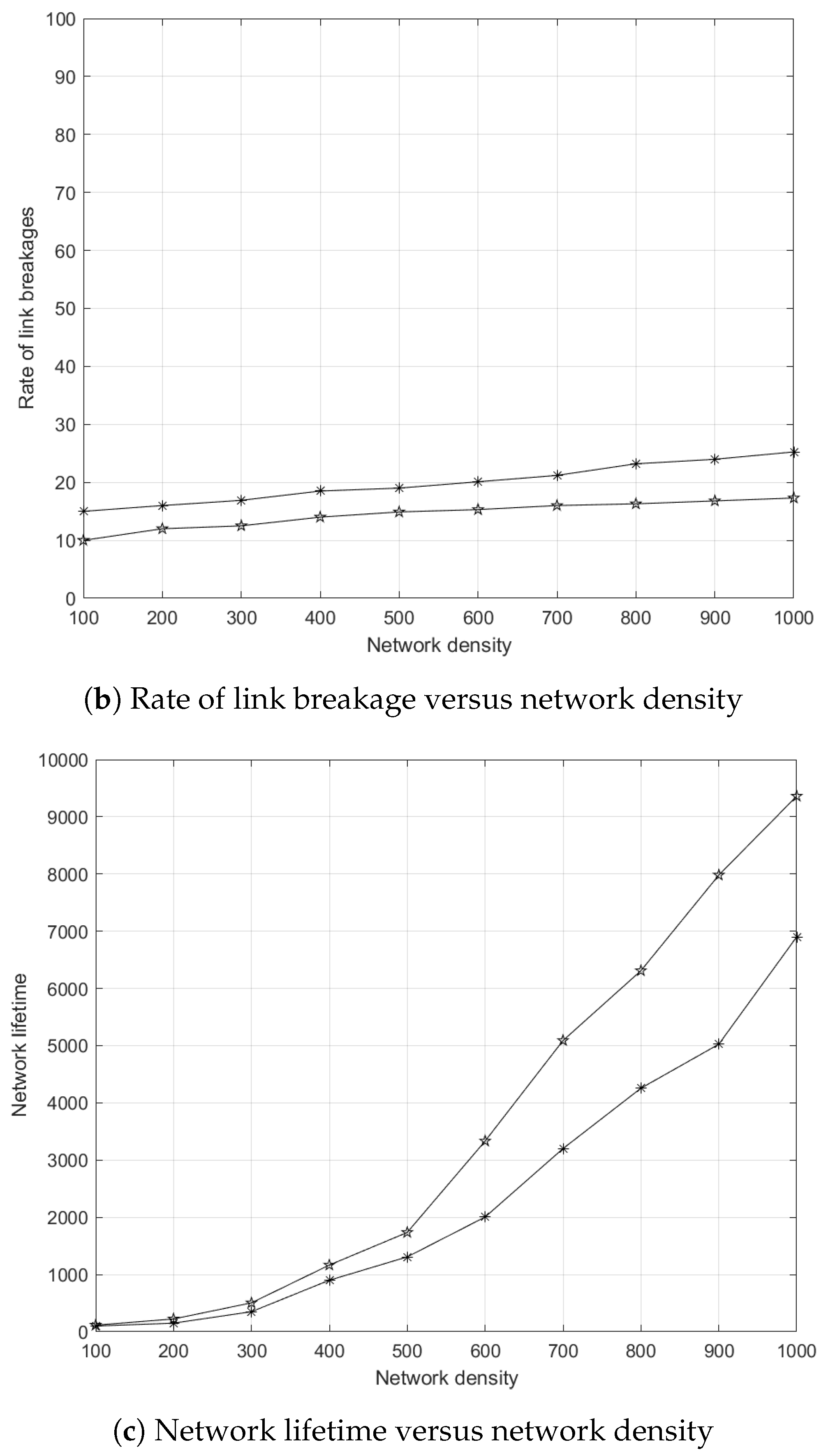
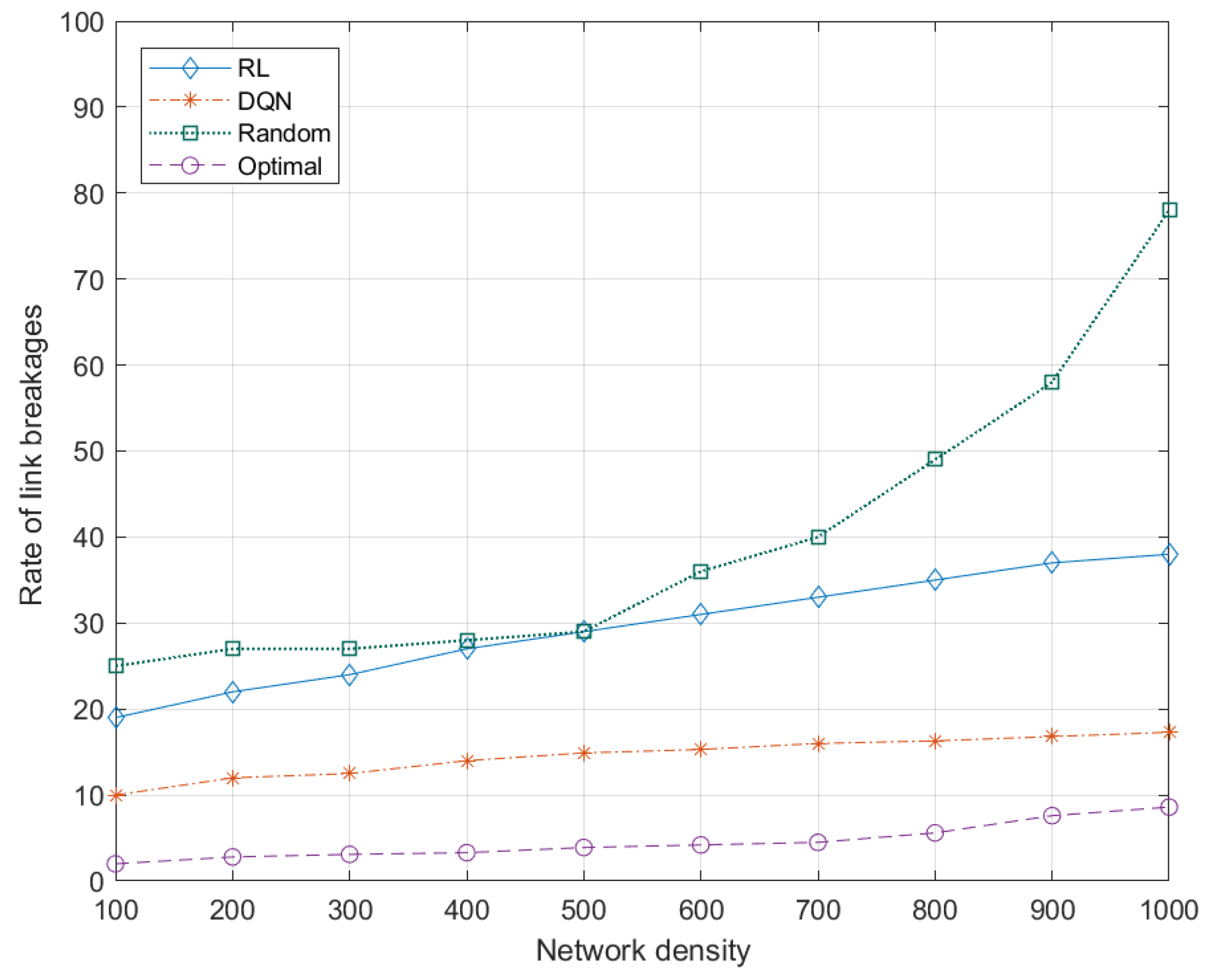
5.7.2. Effects of Network Density to Link Breakages

The link breakage of a route increases gradually as network density increases as shown in Figure 10.
DQN outperforms RL with at least 50 % lower link breakages at lower network density (i.e., 100 UAVs), and at least 45 % lower link breakages at higher network density (i.e., 1000 UAVs). Therefore, DQN increases successful data transmission, contributing to higher network stability and throughput. This improvement is attributed to DNN that learns the mobility pattern of UAVs and uses the action-value function to choose the most favorable route with a longer lifetime based on the movement of UAVs. Meanwhile, the random approach has the highest number of link breakages (i.e., up to 80 % ) due to higher energy consumption that causes a higher number of dead nodes which increases the rate of link breakages. In contrast, the optimal approach has the lowest number of link breakages (i.e., from 2 % to 10 % as network density increases) due to the selected route comprised of nodes with lowest mobility.

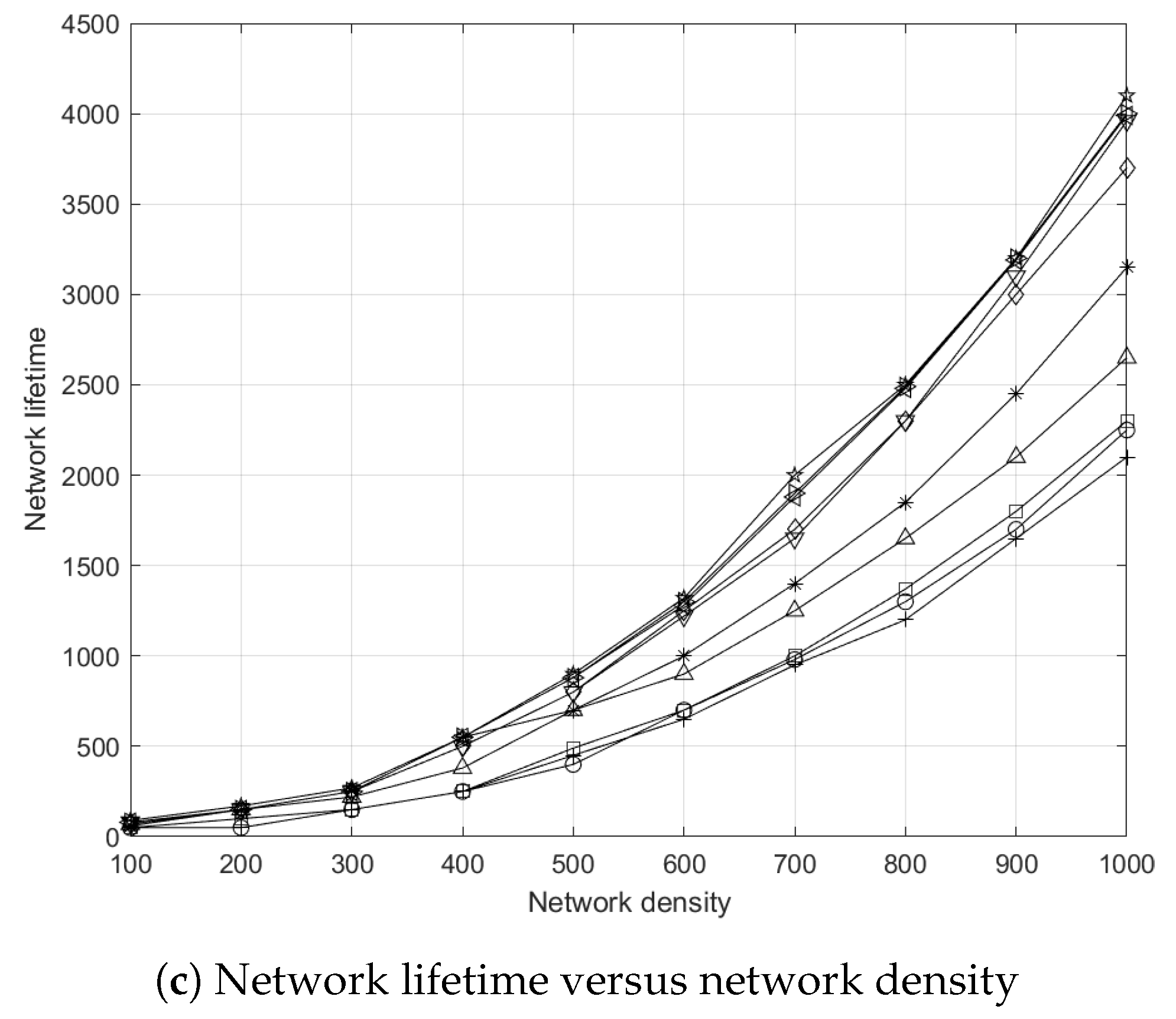
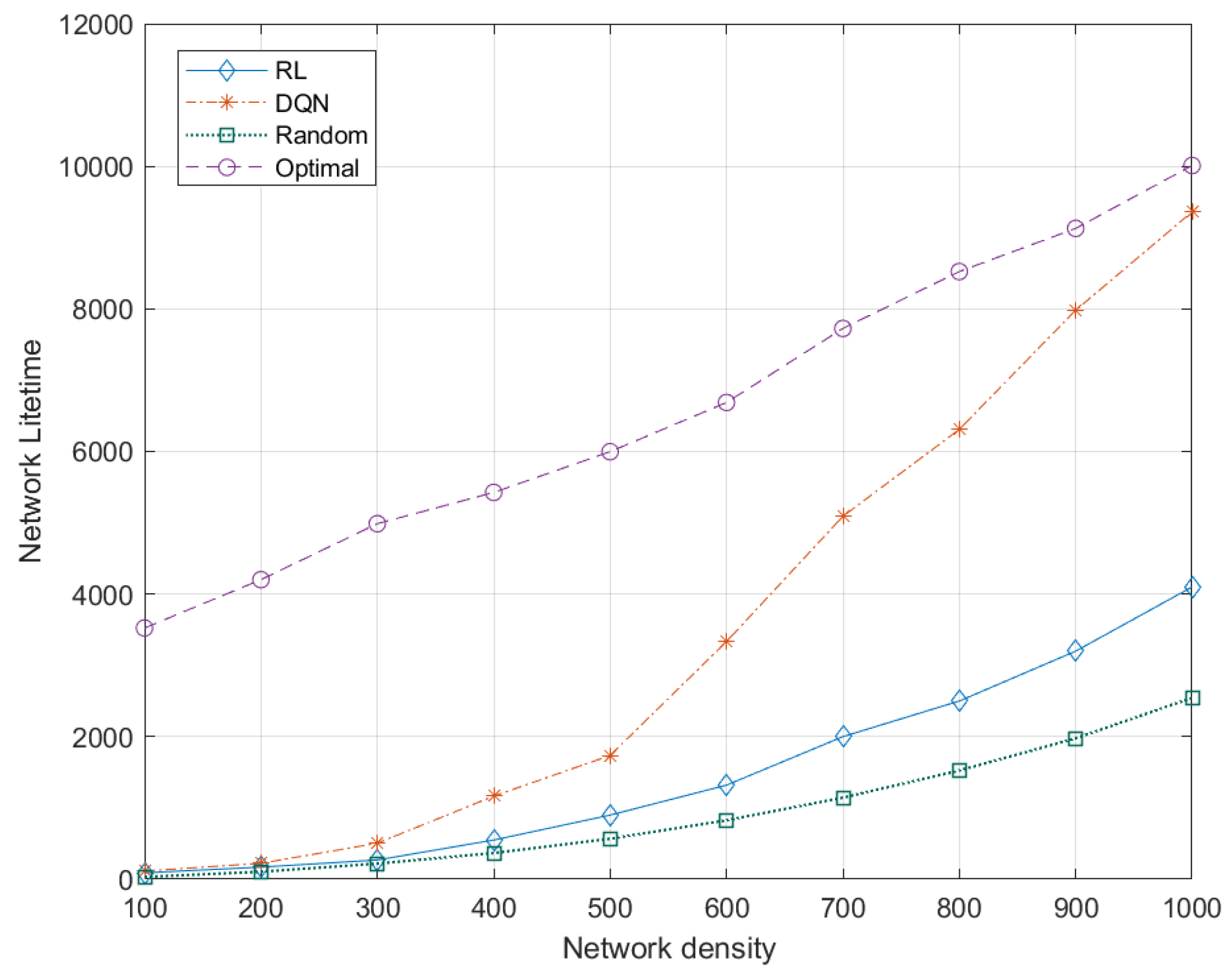
5.7.3. Effects of Network Density to Network Lifetime

The network lifetime of a network increases gradually as network density increases as shown in Figure 11.
DQN and RL performances share almost similar network lifetime at lower network density (i.e., 100 UAVs), and DQN achieves at least 5000 s longer network lifetime at higher network density (i.e., 1000 UAVs). This improvement is attributed to DNN that learns and uses the action-value function to choose the most favorable route with higher residual energy and lower mobility based on node lifetime in order to reduce the overall number of dead nodes. This helps UAVs to perform data transmission over their respective routes for a longer time duration, contributing to higher network lifetime and QoS.
Longer network lifetime (i.e., more than 9000 units) can be seen in Figure 11. This is because DQN agents learn and converge to their respective favorable route, which increases network lifetime. The network lifetime of the random approach is significantly lower as compared to DQN and optimal approaches due to its randomness. The network lifetime of the optimal approach remains constant since the optimal route is selected in each iteration. A higher network lifetime provides stability, contributing to a higher throughput and a reduced signaling overhead caused by route formation.
DQN improves network lifetime by up to 120 % compared to RL, and so it increases network stability.

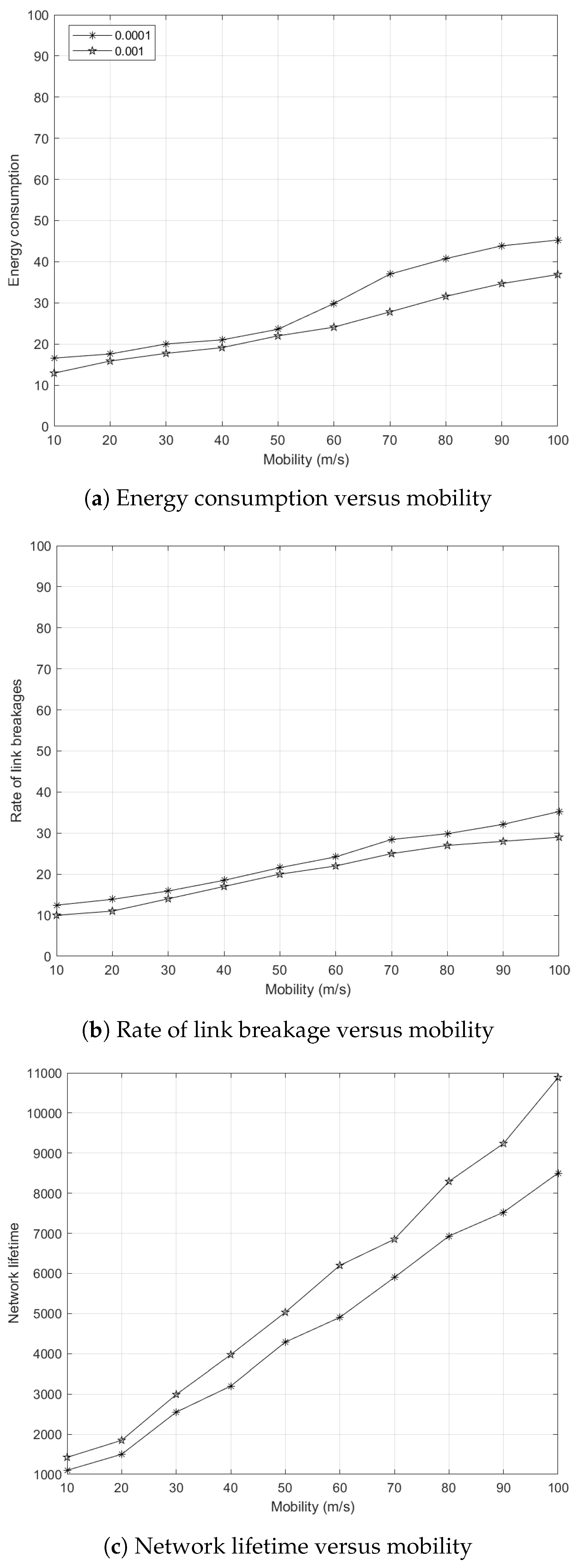
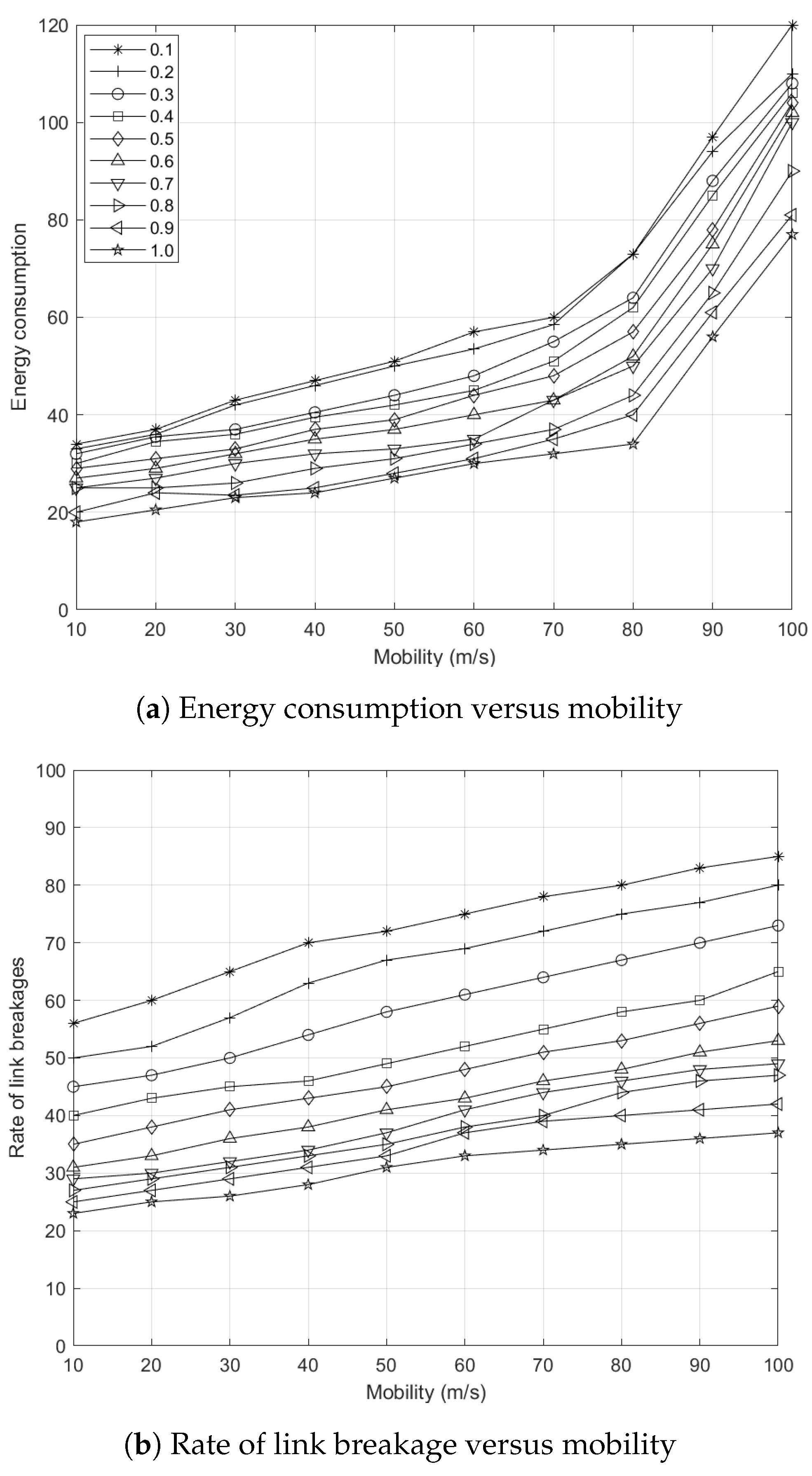
5.7.4. Effects of Node Mobility to Energy Consumption

The energy consumption caused by data transmission from a source UAV to a destination UAV increases gradually as mobility rate increases as shown in Figure 12.
DQN outperforms RL with at least 10 units lower energy consumption at lower mobility rate (i.e., 10 m/s), and at least 40 units lower energy consumption at higher mobility rate (i.e., 100 m/s). Therefore, DQN increases network lifetime and network stability. This improvement is attributed to the use of DQN at CC to predict the state-action value of a route based on the residual energy and mobility of intermediate UAVs with respect to the proximity of a destination UAV. Subsequently, DQN converges to the most favorable route, which has a lower energy consumption as time goes by, across various network planes (i.e., macro-, pico-, and femto-planes). The energy consumption of the DQN and optimal approaches does not vary considerably for most mobility rates upon convergence to the most favorable route It should be noted that (a) the random approach has a higher energy consumption (i.e., more than 95 units) due to its random nature, and (b) the RL approach has a higher energy consumption (i.e., more than 75 units) when the mobility rate is greater than 80 m/s.

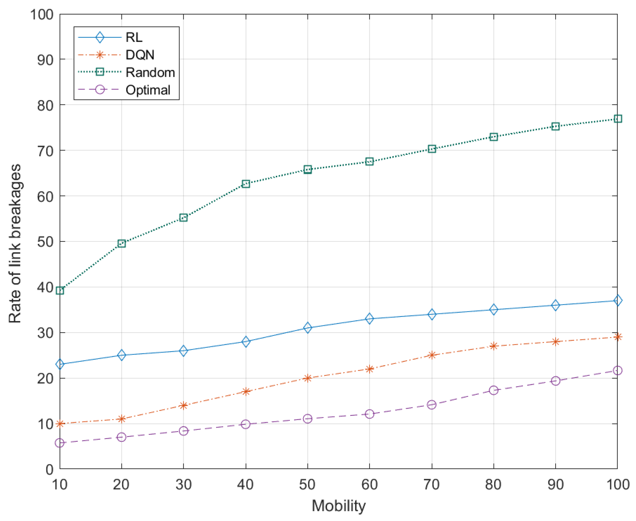
5.7.5. Effects of Node Mobility to Rate of Link Breakages

The link breakage between UAVs of a route increases gradually as node mobility increases as shown in Figure 13.
DQN outperforms RL with at least 60 % lower link breakages at lower node mobility (i.e., 10 m/s), and at least 45 % lower link breakages at higher node mobility (i.e., 100 m/s). Therefore, DQN increases successful data transmission, contributing to higher network stability and throughput. This improvement is attributed to DNN that learns the mobility pattern of UAVs and provides state-action values that help to choose the most favorable route with a lower mobility rate. Meanwhile, the random approach has at least 40 % of the links are broken at lower node mobility (i.e., 10 m/s) and up to 80 % of the links are broken at higher node mobility (i.e., 100 m/s). In contrast, the optimal approach has the lowest number of link breakages from 7 % to 20 % as node mobility increases. It selects a route comprised of nodes with lower mobility and higher residual energy.

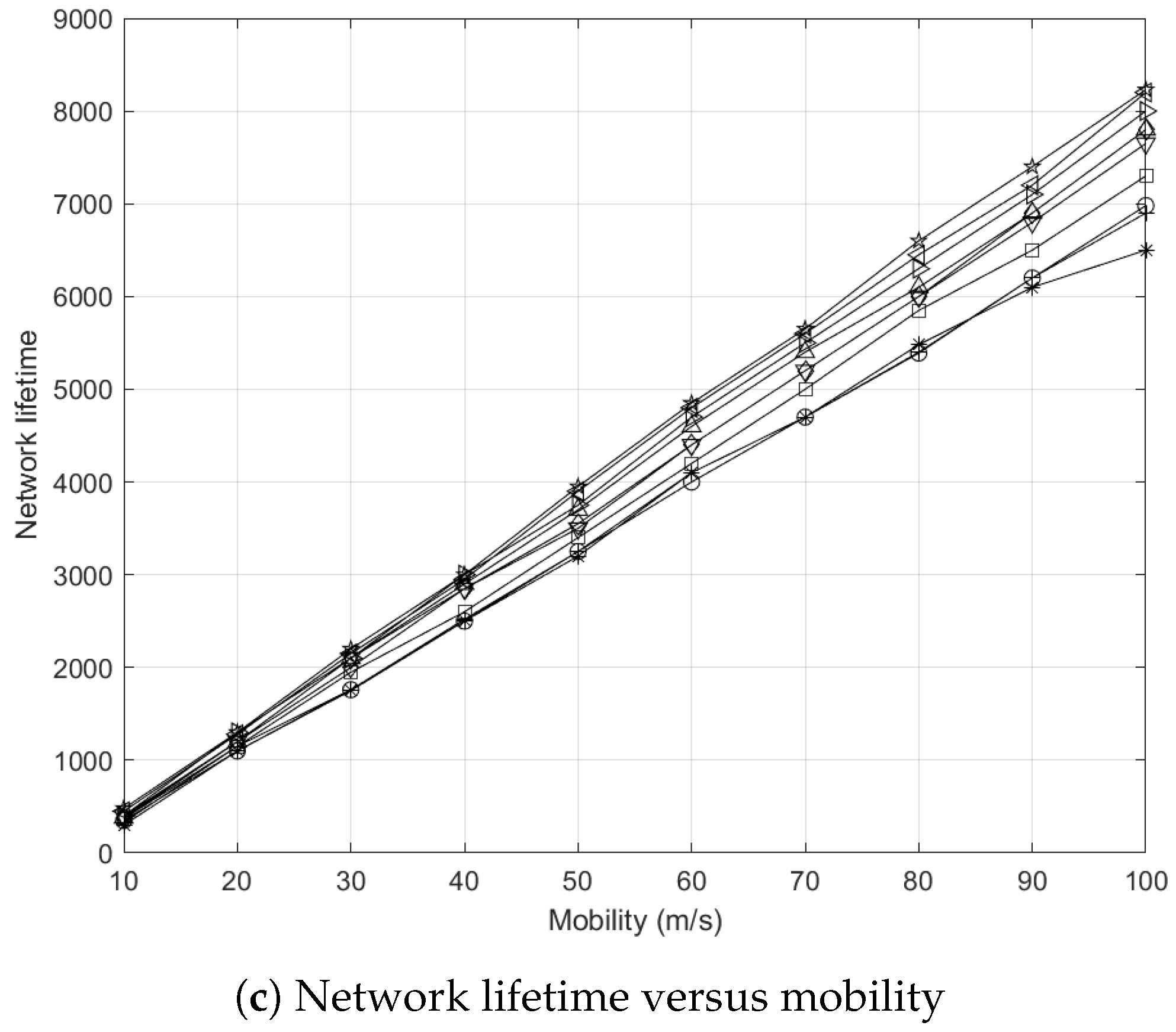
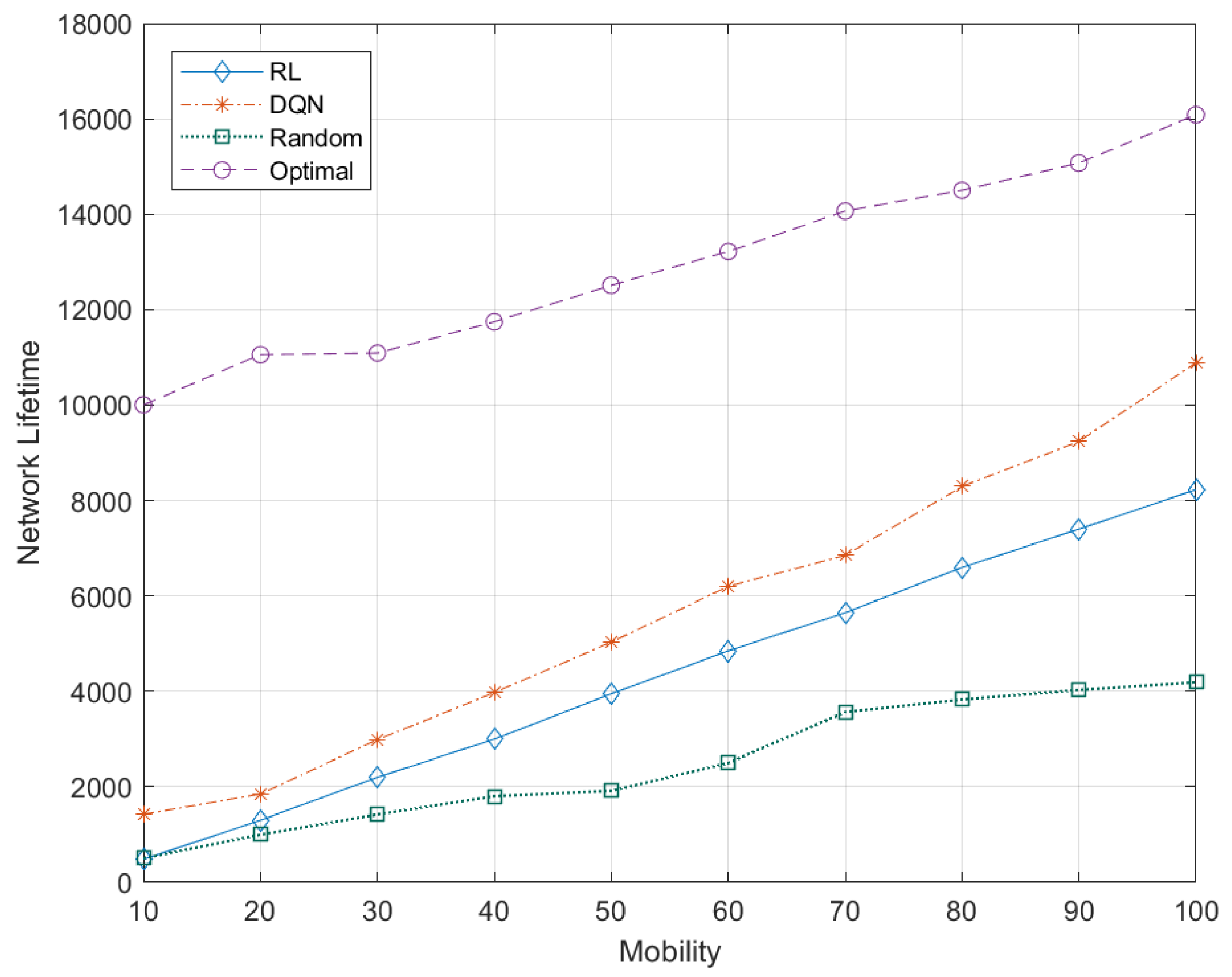
5.7.6. Effects of Node Mobility to Network Lifetime

The network lifetime of a network increases gradually as the mobility rate increases as shown in Figure 14. Note that network lifetime increases with the mobility rate. This is because the number of link breakages increases the need to form new routes. Therefore, energy consumption incurred by data transmission and reception reduces, leading to a longer network lifetime.
DQN outperforms RL with at least three times longer network lifetime at lower mobility rate (i.e., 10 m/s), and DQN achieves at least 5000 s longer network lifetime at higher mobility rate (i.e., 100 m/s). This improvement is attributed to DNN that learns about the states of nodes and predicts the best state-action value to choose the most favorable node with a higher residual energy and a lower mobility rate in order to minimize link disconnection and dead nodes. This helps UAVs to perform data transmission over their respective routes for a longer time duration, contributing to higher network lifetime and QoS.
Longer network lifetime (i.e., more than 16,000 units) can be seen for the optimal approach at higher mobility rate in Figure 14. This is because DQN agents learn and converge to their respective favorable routes, which increases network lifetime. The network lifetime of the random approach is significantly lower as compared to DQN, RL, and optimal approaches due to its randomness. A higher network lifetime provides stability, contributing to a higher throughput and a reduced signaling overhead caused by route formation.
DQN improves network lifetime by up to 60 % and 120 % compared to RL and random approaches, respectively, and so it increases network stability.

5.8. Complexity Analysis

We investigate the computational, message and storage complexities of the DQN algorithm. We have taken the inspiration from [60] for complexity analysis. The complexity has different levels: (a) algorithm-wise for a single iteration in the execution of the DQN algorithm, (b) agent-wise all possible state-action pairs at the agent level, and (c) network-wide at the network level. The parameters for complexity analysis are shown in Table 7.
Computational complexity defines the number of execution cycles required to predict the state-action value for all state-action pairs of the DQN agents. In DQN (see Algorithm 1), the computational complexity of training is O C t = O ( t = 2 X C t ) , where O ( C t ) represents the complexity of a single iteration of training at time t { 1 , 2 , X } (see steps 6 to 16 in Algorithm 1). The algorithm-wise computational complexity is O ( A C t ) , which is incurred whenever an agent i updates network parameters to achieve the desired target function upon receiving a state-action value, and each state has A actions (see step 14 in Algorithm 1). The agent-wise complexity is O ( S A C ) since an agent i updates its network parameters all the state-action pairs. The network-wide complexity is O ( I S A C ) in a network with I agents.
Meanwhile, in the traditional RL approach (see Algorithm 2), the algorithm-wise complexity is O ( A ) , which is incurred when an agent i updates its Q-value upon receiving a delayed reward and each state has A actions (see step 9 in Algorithm 2) The agent-wise complexity is O ( S A ) since an agent i updates its Q-value for all state-action pairs. The network-wide complexity is O ( I S A ) in a network with I agents.
Message complexity defines the number of messages exchanged among the agents to update a state-action value. In DQN (see Algorithm 1), the algorithm-wise message complexity is J (see step 16 in Algorithm 1), which is incurred whenever an agent i exchanges shared local and global information with CC and DCs. Similarly, the agent-wise complexity is J . The network-wide complexity is I J in a network with I agents. Meanwhile, the traditional RL approach and DQN have similar algorithm-wise, agent-wise, and network-wise message complexities (see step 10 in Algorithm 2).
Storage complexity defines the number of connections between a pair of neurons in DNN used for calculating the state-action values. In DQN (see Figure 3), the number of neurons in the nth layer is H n , and the number of layers is N. Therefore, the storage complexity of the nth layer is O ( H n 1 H n + H n H n + 1 + H n + 1 H n + 2 + + H N 1 H N ) , which represents the storage required for connections between layers (i.e., input, hidden, and output layers), and so the storage complexity is O ( n = 2 N ( H n 1 H n ) ) can be denoted as H for simplicity (see steps 10 and 11 in Algorithm 1). The agent-wise storage complexity is O ( S A H ) . Thus, the network-wide storage complexity is O ( I S A H ) in a network with I agents.
Meanwhile, in the traditional RL approach (see Algorithm 2), the algorithm-wise complexity is 1 whenever an agent i stores the Q-value of a state-action pair (see step 9 in Algorithm 2). The agent-wise complexity is ≤ ( S A ) whenever an agent i updates its Q-values for all the state-action pairs. The network-wide complexity is O ( I S A ) in a network with I agents.

6. Conclusions

Deep Q-network (DQN), which is based on reinforcement learning (i.e., Q-learning) and deep learning (i.e., deep neural network (DNN)), enables an agent to select the best possible action under a particular state. This article presents an intelligent cluster-based routing scheme to improve network stability, network lifetime, and energy efficiency in 5G-based flying ad hoc networks. Our proposed scheme ensures the recency of data among central controller (CC) and distributed controller (DC) in order to achieve a balanced enhancement between global and local network performances. DNN enables agents to learn about states (i.e., residual energy and the mobility rate) of agents to predict state-action values. Mini batches of experiences are used for the run-time learning of DNN. There are three features that help to achieve a higher convergence rate towards the most favorable route with higher residual energy and lower mobility. First, the delayed reward, which is part of an experience from the replay memory is used to perform training in order to improve the prediction of state-action values in a dynamic environment. Second, the decaying variable ε d e c a y is used to tend towards exploitation from exploration as the number of episodes increases. Thirdly, mini batches of run-time values of states from the replay memory are used to training and minimizing a loss function. Our proposed scheme is compared with the traditional reinforcement learning and the random approaches and has shown to improve energy efficiency by up to 20 % and 100 % and network lifetime by up to 60 % and 120 % , and to reduce the rate of link breakages by up to 50 % and 80 % , respectively.

7. Future Work

Further research can be pursued to investigate the following open issues. First, vertical routing can be further enhanced to reduce routing overhead incurred to establish and maintain inter- and intra-cluster, and inter- and intra-plane, routes by enabling clusters to adjust their cluster sizes for achieving the optimal number of nodes in a cluster (or the optimal cluster size). This helps the clusters to prolong the cluster lifetime for providing robust data transmission, as well as self-organize traffic load for achieving load balancing among themselves. With improved cluster stability and scalability, vertical routing is expected to improve its route stability. Second, other variants of DQN [63] can be adopted: (a) deep deterministic policy gradient (DDPG) [64] is an actor–critic approach that improves the stability of learning in continuous action space, which is preferred for our vertical routing approach with continuous action space. DDPG aims to achieve the optimal policy which has the highest accumulated reward, rather than the highest Q-value in each state, which may not be optimal; and (b) double DQN [27,65] uses two identical neural networks, whereby one learns during experience replay, just like DQN does, and the other one is a copy of the last episode of the first network. It solves the overestimation of Q-value caused by selecting actions with the highest Q-values at all times. Addressing overestimation helps double DQN to converge to the most favorable route with reduced computational complexity. Third, a mini-batch from the replay memory consists of experiences with higher occurrences rather than distinctive experiences. This can cause overfitting in which DNN fits “too well" to the limited set of the training data, causing sub-optimal actions to be selected. Redundant experiences in a mini batch can be removed to address this so that distinctive experiences can be selected with equal chances. Fourth, further investigation can be carried out in different scenarios with different amounts of white spaces, types of terrain typologies, and types of obstacles (e.g., natural and human-made).

Author Contributions

Conceptualization, M.F.K., K.-L.A.Y., M.H.L., M.A.I. and Y.-W.C.; methodology, M.F.K., K.-L.A.Y., M.H.L., M.A.I. and Y.-W.C.; investigation, M.F.K.; resources, K.-L.A.Y., M.H.L., M.A.I. and Y.-W.C.; data curation, M.F.K.; writing—original draft preparation, M.F.K.; writing—review and editing, K.-L.A.Y., M.H.L., M.A.I. and Y.-W.C.; visualization, M.F.K., K.-L.A.Y., M.H.L., M.A.I. and Y.-W.C.; project administration, K.-L.A.Y.; funding acquisition, K.-L.A.Y. and M.H.L. All authors have read and agreed to the published version of the manuscript.

Funding

This work was supported by the Malaysian Ministry of Education under Fundamental Research Grant Scheme through the “A Novel Clustering Algorithm based on Reinforcement Learning for the Optimization of Global and Local Network Performances in Mobile Networks” project with the grant number FRGS/1/2019/ICT03/SYUC/01/1.

Institutional Review Board Statement

Not applicable.

Informed Consent Statement

Not applicable.

Data Availability Statement

Data sharing not applicable.

Conflicts of Interest

The authors declare no conflict of interest.

Abbreviations

The following abbreviations are used in this manuscript:
5GFifth generation.
CCCentralized controller.
CGCluster gateway.
CHCluster head.
CMCluster member.
D2DDevice-to-device.
DCDistributed controller.
DNNDeep neural network.
DQNDeep Q-network.
DRLDeep reinforcement learning.
FANETsFlying ad hoc networks.
LETLink expiration time.
QoSQuality of service.
RLReinforcement learning.
UAVsUnmanned aerial vehicles.
UEUser equipment.
VCGVertical cluster gateway.

References

  1. Huang, X.L.; Ma, X.; Hu, F. Machine learning and intelligent communications. Mob. Netws. Appl. 2018, 23, 68–70. [Google Scholar] [CrossRef] [Green Version]
  2. Khan, M.F.; Yau, K.-L.A.; Noor, R.M.; Imran, M.A. Survey and taxonomy of clustering algorithms in 5G. J. Netw. Comput. Appl. 2020, 154, 201–221. [Google Scholar] [CrossRef]
  3. Song, Q.; Jin, S.; Zheng, F.-C. Completion time and energy consumption minimization for UAV-enabled multicasting. IEEE Wirel. Commun. Lett. 2019, 8, 821–824. [Google Scholar] [CrossRef]
  4. Oubbati, O.; Atiquzzaman, M.; Ahanger, T.; Ibrahim, A. Softwarization of UAV networks: A survey of applications and future trends. IEEE Access 2020, 8, 98073–98125. [Google Scholar] [CrossRef]
  5. Alzahrani, B.; Oubbati, O.; Barnawi, A.; Atiquzzaman, M.; Alghazzawi, D. UAV assistance paradigm: State-of-the-art in applications and challenges. J. Netw. Comput. Appl. 2020, 166, 102706. [Google Scholar] [CrossRef]
  6. Oubbati, O.; Mozaffari, M.; Chaib, N.; Lorenz, P.; Atiquzzaman, M.; Jamalipour, A. ECaD: Energy-efficient routing in flying ad hoc networks. Int. J. Commun. Syst. 2019, 32, e4156. [Google Scholar] [CrossRef] [Green Version]
  7. Kamel, M.; Hamouda, W.; Youssef, A. Ultra-dense networks: A survey. IEEE Commun. Surv. Tutor. 2016, 18, 2522–2545. [Google Scholar] [CrossRef]
  8. Shaikh, F.S.; Wismüller, R. Routing in multi-hop cellular device-to-device (D2D) networks: A survey. IEEE Commun. Tutor. 2018, 20, 2622–2657. [Google Scholar] [CrossRef]
  9. Chandrasekhar, V.; Andrews, J.; Gatherer, A. Femtocell networks: A survey. arXiv 2008, arXiv:0803.0952. [Google Scholar] [CrossRef] [Green Version]
  10. Li, Q.C.; Niu, H.; Papathanassiou, A.T.; Wu, G. 5G network capacity: Key elements and technologies. IEEE Veh. Technol. Mag. 2014, 9, 71–78. [Google Scholar] [CrossRef]
  11. Jiang, D.; Liu, G. An overview of 5G requirements. In 5G Mobile Communications; Springer: Cham, Switzerland, 2017; pp. 3–26. [Google Scholar]
  12. Imran, A.; Zoha, A.; Abu-Dayya, A. Challenges in 5G: How to empower SON with big data for enabling 5G. IEEE Netw. 2014, 28, 27–33. [Google Scholar] [CrossRef]
  13. Habiba, U.; Hossain, E. Auction mechanisms for virtualization in 5G cellular networks: Basics, trends, and open challenges. IEEE Commun. Surv. Tutor. 2018, 20, 2264–2293. [Google Scholar] [CrossRef]
  14. Yang, Q.; Jang, S.-J.; Yoo, S.-J. Q-learning-based fuzzy logic for multi-objective routing algorithm in flying ad hoc networks. Wirel. Pers. Commun. 2020, 113, 115–138. [Google Scholar] [CrossRef]
  15. He, C.; Liu, S.; Han, S. A fuzzy logic reinforcement learning-based routing algorithm for flying ad hoc networks. In Proceedings of the IEEE International Conference on Computing, Networking and Communications (ICNC), Big Island, HI, USA, 17–20 February 2020; pp. 987–991. [Google Scholar]
  16. Bekmezci, I.; Sahingoz, O.K.; Temel, A. Flying ad-hoc networks (FANETs): A survey. Ad Hoc Netws. 2013, 11, 1254–1270. [Google Scholar] [CrossRef]
  17. Wang, H.; Haitao, Z.; Zhang, J.; Ma, D.; Li, J.; Wei, J. Survey on unmanned aerial vehicle networks: A cyber physical system perspective. IEEE Commun. Surv. Tutor. 2019, 22, 1027–1070. [Google Scholar] [CrossRef] [Green Version]
  18. Khan, M.F.; Yau, K.-L.A.; Noor, R.M.; Imran, M.A. Routing schemes in fanets: A survey. Sensors 2020, 20, 38. [Google Scholar] [CrossRef] [Green Version]
  19. Chaumette, S.; Laplace, R.; Mazel, C.; Mirault, R.; Dunand, A.; Lecoutre, Y.; Perbet, J.N. Carus, an operational retasking application for a swarm of autonomous UAVs: First return on experience. In Proceedings of the IEEE Military Communications Conference—Milcom, Baltimore, MD, USA, 7–10 November 2011; pp. 2003–2010. [Google Scholar]
  20. Quaritsch, M.; Kruggl, K.; Wischounig-Strucl, D.; Bhattacharya, S.; Shah, M.; Rinner, B. Networked UAVs as aerial sensor network for disaster management applications. Elektrotechnik Inf. 2010, 127, 56–63. [Google Scholar] [CrossRef]
  21. Alshbatat, A.I.; Alsafasfeh, Q. Cooperative decision making using a collection of autonomous quad rotor unmanned aerial vehicle interconnected by a wireless communication network. Glob. J. Technol. 2012, 1, 212–218. [Google Scholar]
  22. Arafat, M.Y.; Moh, S. Location-aided delay tolerant routing protocol in UAV networks for post-disaster operation. IEEE Access 2018, 6, 59891–59906. [Google Scholar] [CrossRef]
  23. Mekikis, P.V.; Antonopoulos, A.; Kartsakli, E.; Alonso, L.; Verikoukis, C. Communication recovery with emergency aerial networks. IEEE Trans. Consum. Electron. 2017, 63, 291–299. [Google Scholar] [CrossRef]
  24. Arafat, M.Y.; Moh, S. A survey on cluster-based routing protocols for unmanned aerial vehicle networks. IEEE Access 2018, 7, 498–516. [Google Scholar] [CrossRef]
  25. Arafat, M.Y.; Moh, S. Routing protocols for unmanned aerial vehicle networks: A survey. IEEE Access 2019, 7, 99694–99720. [Google Scholar] [CrossRef]
  26. Mkiramweni, M.; Yang, C.; Li, J.; Zhang, W. A survey of game theory in unmanned aerial vehicles communications. IEEE Commun. Surv. Tutor. 2019, 21, 3386–3416. [Google Scholar] [CrossRef]
  27. Liu, W.; Si, P.; Sun, E.; Li, M.; Fang, C.; Zhang, Y. Green mobility management in UAV-assisted IoT based on dueling DQN. In Proceedings of the IEEE International Conference on Communications (ICC), Shanghai, China, 20–24 May 2019; pp. 1–6. [Google Scholar]
  28. Xie, J.; Yu, F.; Huang, T.; Xie, R.; Liu, J.; Wang, C.; Liu, Y. A survey of machine learning techniques applied to software defined networking (SDN): Research issues and challenges. IEEE Commun. Surv. Tutor. 2018, 21, 393–430. [Google Scholar] [CrossRef]
  29. Arafat, M.Y.; Moh, S. Localization and clustering based on swarm intelligence in UAV networks for emergency communications. IEEE Internet Things J. 2019, 6, 8958–8976. [Google Scholar] [CrossRef]
  30. Arafat, M.Y.; Moh, S. Bio-inspired approaches for energy-efficient localization and clustering in UAV networks for monitoring wildfires in remote areas. IEEE Access 2021, 9, 18649–18669. [Google Scholar] [CrossRef]
  31. Arafat, M.Y.; Moh, S. A Q-Learning-Based Topology-Aware Routing Protocol for Flying Ad Hoc Networks. IEEE Internet Things J. 2021, 9, 1985–2000. [Google Scholar] [CrossRef]
  32. Ndiaye, M.; Hancke, G.; Abu-Mahfouz, A. Software defined networking for improved wireless sensor network management: A survey. Sensors 2017, 17, 1031. [Google Scholar] [CrossRef] [PubMed]
  33. Wei, X.; Yang, H.; Huang, W. A Genetic-Algorithm-Based Optimization Routing for FANETs. Front. Neurorobot. 2021, 15, 81. [Google Scholar] [CrossRef]
  34. Lee, S.W.; Ali, S.; Yousefpoor, M.S.; Yousefpoor, E.; Lalbakhsh, P.; Javaheri, D.; Rahmani, A.M.; Hosseinzadeh, M. An energy-aware and predictive fuzzy logic-based routing scheme in flying ad hoc networks (fanets). IEEE Access 2021, 9, 129977–130005. [Google Scholar] [CrossRef]
  35. da Costa, L.A.L.; Kunst, R.; de Freitas, E.P. Q-FANET: Improved Q-learning based routing protocol for FANETs. Comput. Netws. 2021, 198, 108379. [Google Scholar] [CrossRef]
  36. Hussain, A.; Hussain, T.; Faisal, F.; Ali, I.; Khalil, I.; Nazir, S.; Khan, H.U. DLSA: Delay and Link Stability Aware Routing Protocol for Flying Ad-hoc Networks (FANETs). Wirel. Pers. Commun. 2021, 121, 2609–2634. [Google Scholar] [CrossRef]
  37. Xing, W.; Huang, W.; Hua, Y. A Boltzmann Machine Optimizing Dynamic Routing for FANETs; Creative Commons: Mountain View, CA, USA, 2021. [Google Scholar]
  38. Rajoria, S.; Trivedi, A.; Godfrey, W.W. A comprehensive survey: Small cell meets massive MIMO. Phys. Commun. 2018, 26, 40–49. [Google Scholar] [CrossRef]
  39. Kreutz, D.; Ramos, F.M.; Verissimo, P.; Rothenberg, C.E.; Azodolmolky, S.; Uhlig, S. Software-defined networking: A comprehensive survey. Proc. IEEE 2015, 103, 14–76. [Google Scholar] [CrossRef] [Green Version]
  40. Ahmad, I.; Namal, S.; Ylianttila, M.; Gurtov, A. Security in software defined networks: A survey. IEEE Commun. Surv. Tutor. 2015, 17, 2317–2346. [Google Scholar] [CrossRef]
  41. Kobo, H.I.; Abu-Mahfouz, A.M.; Hancke, G.P. A survey on software-defined wireless sensor networks: Challenges and design requirements. IEEE Access 2017, 5, 1872–1899. [Google Scholar] [CrossRef]
  42. Bailis, P.; Ghodsi, A. Eventual consistency today: Limitations, extensions, and beyond. Queue 2013, 11, 20–33. [Google Scholar] [CrossRef] [Green Version]
  43. Mohammadi, M.; Al-Fuqaha, A.; Guizani, M.; Oh, J.-S. Semisupervised deep reinforcement learning in support of IoT and smart city services. IEEE Internet Things J. 2017, 5, 624–635. [Google Scholar] [CrossRef] [Green Version]
  44. Ye, J.; Zhang, C.; Lei, H.; Pan, G.; Ding, Z. Secure UAV-to-UAV systems with spatially random UAVs. IEEE Wirel. Commun. Lett. 2018, 8, 564–567. [Google Scholar] [CrossRef]
  45. Khan, A.; Aftab, F.; Zhang, Z. BICSF: Bio-inspired clustering scheme for FANETs. IEEE Access 2019, 7, 31446–31456. [Google Scholar] [CrossRef]
  46. Rasheed, F.; Yau, K.-L.A.; Low, Y.-C. Deep reinforcement learning for traffic signal control under disturbances: A case study on Sunway City, Malaysia. Future Gener. Comput. Syst. 2020, 109, 431–445. [Google Scholar] [CrossRef]
  47. Sharma, J.; Andersen, P.-A.; Granmo, O.-C.; Goodwin, M. Deep q-learning with q-matrix transfer learning for novel fire evacuation environment. IEEE Trans. Syst. Man Cybern. Syst. 2020, 51, 7363–7381. [Google Scholar] [CrossRef] [Green Version]
  48. Hussain, F.; Hussain, R.; Anpalagan, A.; Benslimane, A. A new block-based reinforcement learning approach for distributed resource allocation in clustered IoT networks. IEEE Trans. Veh. Technol. 2020, 69, 2891–2904. [Google Scholar] [CrossRef]
  49. Fu, S.; Yang, F.; Xiao, Y. AI inspired intelligent resource management in future wireless network. IEEE Access 2020, 8, 425–433. [Google Scholar] [CrossRef]
  50. Atienza, R. Advanced Deep Learning with TensorFlow 2 and Keras: Apply DL, GANs, VAEs, Deep RL, Unsupervised Learning, Object Detection and Segmentation, and More; Packt Publishing Ltd.: Birmingham, UK, 2020. [Google Scholar]
  51. Menczer, F.; Fortunato, S.; Davis, C.A. A First Course in Network Science; Cambridge University Press: Cambridge, UK, 2020. [Google Scholar]
  52. Ali, H.; Shahzad, W.; Khan, F.A. Energy-efficient clustering in mobile ad-hoc networks using multi-objective particle swarm optimization. Appl. Soft Comput. 2012, 12, 1913–1928. [Google Scholar] [CrossRef]
  53. Xie, J.; Wan, Y.; Kim, J.H.; Fu, S.; Namuduri, K. A survey and analysis of mobility models for airborne networks. IEEE Commun. Surv. Tutor. 2014, 16, 1221–1238. [Google Scholar] [CrossRef]
  54. Khan, M.F.; Yau, K.L.A. Route Selection in 5G-based Flying Ad-hoc Networks using Reinforcement Learning. In Proceedings of the 10th IEEE International Conference on Control System, Computing and Engineering (ICCSCE), Penang, Malaysia, 21–22 August 2020; pp. 23–28. [Google Scholar]
  55. Aadil, F.; Raza, A.; Khan, M.F.; Maqsood, M.; Mehmood, I.; Rho, S. Energy aware cluster-based routing in flying ad-hoc networks. Sensors 2018, 18, 1413. [Google Scholar] [CrossRef] [PubMed] [Green Version]
  56. Khelifi, F.; Bradai, A.; Singh, K.; Atri, M. Localization and energy efficient data routing for unmanned aerial vehicles: Fuzzy-logic-based approach. IEEE Commun. Mag. 2018, 56, 129–133. [Google Scholar] [CrossRef]
  57. Sirmollo, C.Z.; Bitew, M.A. Mobility-Aware Routing Algorithm for Mobile Ad Hoc Networks. Wirel. Commun. Mob. Comput. 2021, 2021, 12. [Google Scholar] [CrossRef]
  58. Mazloomi, N.; Gholipour, M.; Zaretalab, A. Efficient configuration for multi-objective QoS optimization in wireless sensor network. Ad Hoc Netws. 2022, 125, 102730. [Google Scholar] [CrossRef]
  59. Hussein, W.A.; Ali, B.M.; Rasid, M.F.A.; Hashim, F. Smart geographical routing protocol achieving high QoS and energy efficiency based for wireless multimedia sensor networks. Egypt. Inf. J. 2022, in press. [Google Scholar] [CrossRef]
  60. Ling, M.H.; Yau, K.-L.A.; Qadir, J.; Ni, Q. A reinforcement learning-based trust model for cluster size adjustment scheme in distributed cognitive radio networks. IEEE Trans. Cogn. Commun. Netw. 2018, 5, 28–43. [Google Scholar] [CrossRef] [Green Version]
  61. Musavi, M.; Yau, K.-L.A.; Syed, A.R.; Mohamad, H.; Ramli, N. Route selection over clustered cognitive radio networks: An experimental evaluation. Comput. Commun. 2018, 129, 138–151. [Google Scholar] [CrossRef]
  62. Saleem, Y.; Yau, K.-L.A.; Mohamad, H.; Ramli, N.; Rehmani, M.H. Smart: A spectrum-aware cluster-based routing scheme for distributed cognitive radio networks. Comput. Netws. 2015, 91, 196–224. [Google Scholar] [CrossRef] [Green Version]
  63. Mnih, V.; Kavukcuoglu, K.; Silver, D.; Rusu, A.A.; Veness, J.; Bellemare, M.G.; Graves, A.; Riedmiller, M.; Fidjeland, A.K.; Ostrovski, G.; et al. Human-level control through deep reinforcement learning. Nature 2015, 518, 529–533. [Google Scholar] [CrossRef]
  64. Qiu, C.; Hu, Y.; Chen, Y.; Zeng, B. Deep deterministic policy gradient (DDPG)-based energy harvesting wireless communications. IEEE Internet Things J. 2019, 6, 8577–8588. [Google Scholar] [CrossRef]
  65. Sewak, M. Deep q network DQN, double DQN, and dueling DQN. In Deep Reinforcement Learning; Springer: Singapore, 2019; pp. 95–108. [Google Scholar]
Figure 1. Our framework consists of DQN-based vertical routing over a clustered FANET in a 5G network. Cluster C 1 , 1 is in the macro-plane, clusters C 2 , 1 and C 2 , 2 are in the pico-plane, and cluster C 3 , 1 is in the femto-plane. Gray-shaded area represents a cluster boundary (i.e., the transmission range of a CH) across different network planes. C G 1 , 1 , 1 and C G 3 , 2 , 1 are not connected with CGs of other clusters. Explanation of the function of the network entities is presented in Table 3.
Applsci 12 03665 g001
Figure 2. An example of a cluster structure in a traditional clustered network. Solid line represents the connectivity between a node pair, and dash line represents the connectivity between a CH and a BS.
Applsci 12 03665 g002
Figure 3. An overview of DQN. Main network, characterized by main network parameters θ i , provides Q-value Q ( s i t , a i t ; θ i ) that defines the behavior policy. Target Q-network, characterized by target network parameters θ ¯ i , generates target Q-value Q ( s i t , a i t ; θ ¯ i ) . Both Q ( s i t , a i t ; θ i ) and Q ( s i t , a i t ; θ ¯ i ) are used to calculate a loss function L i ( θ i ) minimized using the gradient descent approach during training. Experiences ( s t k , a t k , r t k , s t + 1 k ) are stored in the replay memory and they are used during training. A mini batch of random experiences from the replay memory are fed into the main and target networks. The DQN agent is incorporated in CC as shown in Figure 1.
Applsci 12 03665 g003
Figure 4. Graphical results for the effects of network density on RL. Learning rate α = 1.0 achieves the lowest energy consumption and rate of link breakages, as well as the highest network lifetime.
Applsci 12 03665 g004aApplsci 12 03665 g004b
Figure 5. Graphical results for the effects of mobility on RL. Learning rate α = 1.0 achieves the lowest energy consumption and rate of link breakages, as well as the highest network lifetime.
Applsci 12 03665 g005aApplsci 12 03665 g005b
Figure 6. Graphical results for the effects of network density on DQN. Learning rate α = 0.001 achieves the lowest energy consumption and rate of link breakages, as well as the highest network lifetime.
Applsci 12 03665 g006aApplsci 12 03665 g006b
Figure 7. Graphical results for the effects of mobility on DQN. Learning rate α = 0.001 achieves the lowest energy consumption and rate of link breakages, as well as the highest network lifetime.
Applsci 12 03665 g007
Figure 8. Convergence of the DQN algorithm with different learning rates. A higher learning rate α shows a faster convergence as compare to a lower learning rate α .
Applsci 12 03665 g008
Figure 9. Energy consumption increases with respect to network density. DQN achieves lower values as compared to RL and random approaches. Lower energy consumption improves the energy efficiency of a network.
Applsci 12 03665 g009
Figure 10. Rate of link breakages increases with respect to network density. DQN achieves lower values as compared to RL and random approaches. Lower rate of link breakages improves QoS and network lifetime.
Applsci 12 03665 g010
Figure 11. Network lifetime increases with respect to network density. DQN achieves higher values as compared to RL and random approaches. Higher network lifetime improves QoS and network stability.
Applsci 12 03665 g011
Figure 12. Energy consumption increases with respect to mobility rate. DQN achieves lower values as compared to RL and random approaches. Lower energy consumption improves the energy efficiency of a network.
Applsci 12 03665 g012
Figure 13. Rate of link breakages increases with respect to node mobility. DQN achieves lower values as compared to RL and random approaches. Lower rate of link breakages improves QoS and network lifetime.
Applsci 12 03665 g013
Figure 14. Network lifetime increases with respect to mobility rate. DQN achieves higher values as compared to RL and random approaches. Higher network lifetime improves QoS and network stability.
Applsci 12 03665 g014
Table 1. General notations.
NotationDescription
n i Node i N .
θ i Direction of node n i where, i N .
v i Velocity of node n i where, i N .
TTransmission range.
t p Data lifetime.
τ Data lifetime threshold.
x i , y i , z i Coordinates of node n i in three dimensions, where i N .
tTime
D i , j Distance between two nodes n i and n j , where i, j N .
Table 2. Routing notations.
NotationDescription
iNumber of agents, where i = 1 , 2 , 3 , N.
s t i State of an agent i at time t.
m t i Mobility of an agent i at time t.
e t i Residual energy of an agent i at time t.
E r Residual energy of an agent.
a t i Action of an agent i at time t.
ASet of possible actions.
x m , E r h Action (i.e., a selected next-hop node x h ) taken based on mobility m and residual energy E r .
r t ( s t i , a t i , s t + 1 i ) Delayed reward received by an agent i at time t.
Q ( s t i , a t i ) State-action pair or Output Q-value.
μ θ ( s t i , a t i ) Policy for the selection of state-action pair Q-value Q ( s t i , a t i ) .
R m e m Memory for storing the experiences used for training deep neural network.
( s t k , a i k , r t k , s t + 1 k ) k t h experiences stored in reply memory R m e m .
α Learning rate.
γ Discount factor.
ε Exploration rate.
ε m a x Maximum exploration rate.
ε m i n Minimum exploration rate.
ε d e c a y Decaying variable of exploration. ε from maximum exploration rate ε m a x to minimum exploration rate ε m i n .
y i Desired target function.
θ Network parameters of the main network.
θ ¯ Network parameters of the target network.
θ i L i ( θ i ) Gradient descent based on a loss function for network parameters θ .
Table 3. The functions of various network entities are shown in Figure 1.
TerminologiesAbbreviationsFunctions
Unmanned aerial vehicleUAVUAVs are autonomous, small-sized, lightweight flying nodes moving at high speed at low or high altitudes in a three-dimensional space.
Central controllerCCCC makes decisions and manages global tasks (i.e., vertical routing).
Distributed controllerDCDC makes decisions and manages local tasks (e.g., vertical clustering) in a particular network plane.
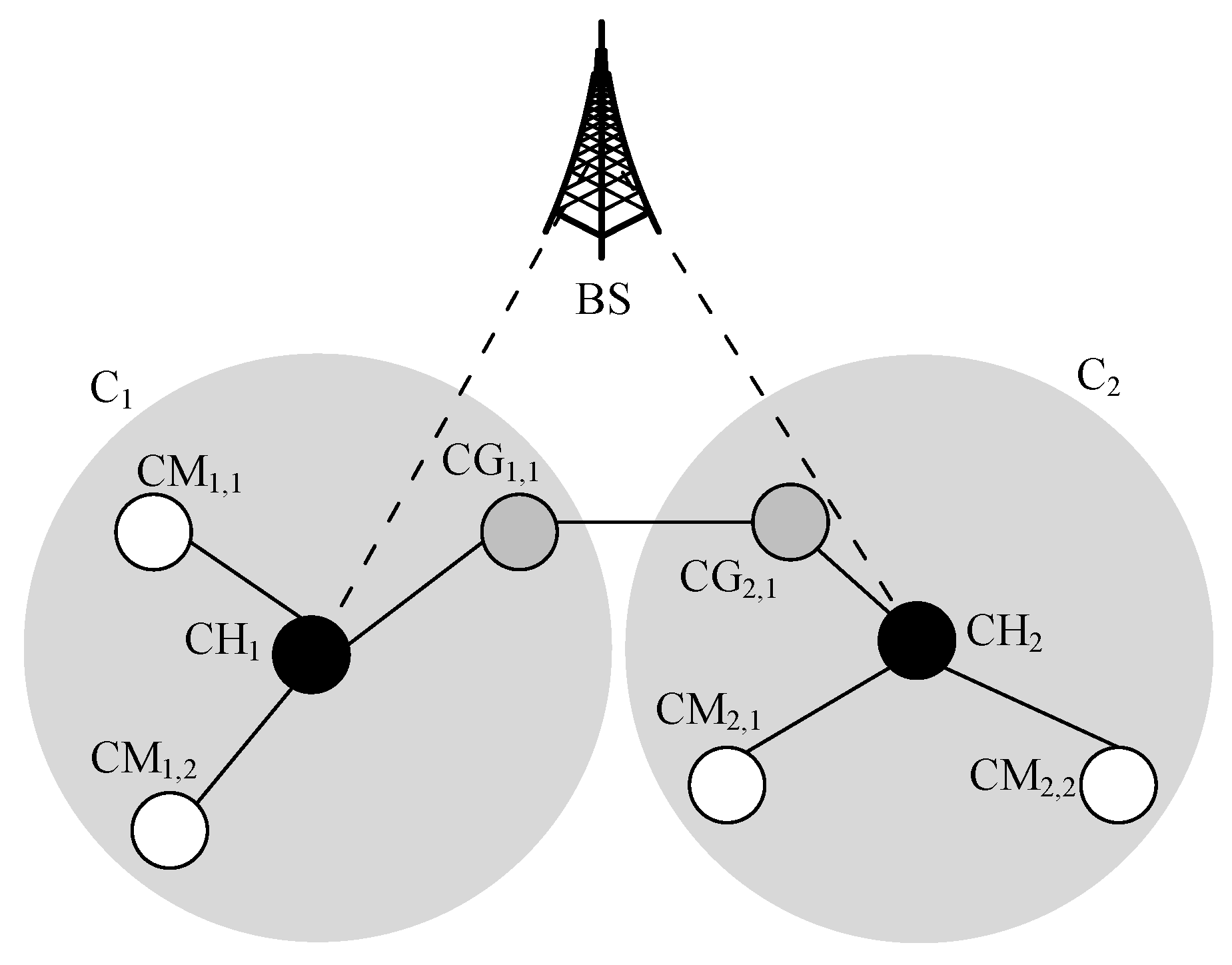
Cluster headCHCH, which serves as the cluster leader, manages and handles cluster-level operations (e.g., routing), and performs intra- and inter-cluster communications.
Cluster memberCMCM, which is associated with a CH, performs intra-cluster communication.
Cluster gatewayCGCG, which is associated with a CH, interacts with neighboring clusters through inter-cluster communication.
Vertical cluster gatewayVCGVCG enables interactions among UAVs in different clusters across different network planes, which is conveniently known as inter-plane communication.
Table 4. Organization of this paper.
SectionDetail
IntroductionSection 1 presents the introduction of FANETs, 5G access network, and the structure of vertical clustering in 5G-based FANET. Furthermore, this section contains the distinguishing aspects of our research, contributions, and organizational structure of paper.
Network ArchitectureSection 2 presents the discussion about core elements of 5G access network (i.e., network planes and controllers). It also presents the discussion on the hybrid framework, functions of controllers, and advantages. It defines the categories of data based on their lifetime, and the significance of fresh data.
System Model and FunctionsSection 3 presents the traditional clustering approach, routing mechanism, and cluster maintenance. It presents a detailed discussion of vertical routing based on a use case scenario as shown in Figure 1. Furthermore, it presents DQN-based vertical routing, the three main components of DQN, and the DQN algorithm as shown in Algorithm 1. It also presents the discussion and algorithm of reinforcement learning as shown in Algorithm 2.
Performance Evaluation, Results and DiscussionSection 4 presents a detailed discussion of the implementation of research, baseline approaches, ranges of important parameters, energy models, the selection of various performance measures, the analysis of RL and DQN approaches based on learning rate, the convergence of proposed schemes, and a comprehensive discussion of simulation results. Furthermore, it presents a complexity analysis including its parameters.
Conclusion and Future WorkSection 5 presents the significant research outcomes and the future research direction.
Table 5. Characteristics of network planes.
Network PlaneCharacteristics
Node Density (Percentage of UAVs)Node Mobility (Meters per Second)Transmission Range (Meters)
Macrocell45%66.7–10010–500
Picocell35%33.4–66.610–300
Femtocell20%0–33.310–100
Table 6. Simulation parameters for the RL and DQN agent.
ParametersRLDQN
Batch size-32
Episodes z10011001
Transmission Range (m)500500
Grid size (km 3 )11
Energy for transmission ( j o u l e )22
Energy for reception ( j o u l e )11
Speed (m/s)10–10010–100
Network density100–1000100–1000
Replay memory size-2000
Discount factor γ 0.950.95
Learning rate α 0.1–1.00.0001–0.001
Exploration rate ε 1.01.0
Minimum exploration rate ε m i n -0.001
Maximum exploration rate ε m a x -1.0
Decaying variable ε d e c a y -0.995
Data lifetime threshold τ zz
Table 7. Parameters for complexity analysis.
ParameterDescription
S Number of states.
A Number of actions for each state.
R Number of rewards for each state-action pair ( s t , a t ) .
I Number of agents in a network.
J Number of neighboring agents of an agent in a network.
C Training complexity.
H Hidden layer complexity.
Publisher’s Note: MDPI stays neutral with regard to jurisdictional claims in published maps and institutional affiliations.

