Article

Research on Output Voltage Stability of Non-Contact Excitation Motor

1
School of Electrical and Information Engineering, Jiangsu University, Zhenjiang 212013, China
2
Automotive Engineering Research Institute, Jiangsu University, Zhenjiang 212013, China
*
Author to whom correspondence should be addressed.
Appl. Sci. 2022, 12(7), 3666; https://doi.org/10.3390/app12073666
Submission received: 12 March 2022 / Revised: 27 March 2022 / Accepted: 31 March 2022 / Published: 6 April 2022

Abstract

:
In recent years, electric vehicles have developed rapidly. However, many electric cars are equipped with permanent magnet synchronous motors. Permanent magnet synchronous motors have several disadvantages: For example, permanent magnets tend to demagnetize at high temperatures. Electrically excited synchronous motors have several excellent properties. First, they are cheaper because the stator and rotor of the motor only need to be wound, which is more affordable than permanent magnets for speed regulation. When the armature current reaches the maximum value, the excitation current can also be adjusted for speed regulation, which makes the speed regulation more flexible. In the case of a short circuit, the corresponding direct-axis current is smaller than the quadrature-axis current, so the fault tolerance is better. Since the traditional electric excitation motor has brushes and slips rings, sparks will be generated during commutation. Therefore, a new excitation method is adopted to make non-contact motor excitation, and the motor operation is safer and more environmentally friendly. At the same time, to ensure that the output power of the non-contact electric excitation motor remains stable, a step-down circuit and power-type fast discrete terminal sliding mode control are added after the full-bridge rectifier circuit to make the excitation current and voltage output of the motor more stable. That is, the output power reaches a steady production. In this paper, an improved sliding mode control algorithm is used to stabilize the output voltage of the non-contact excitation motor, which can still ensure the stable output of the voltage when the equivalent load changes. It is confirmed that the non-contact excitation motor can be applied to various complex situations, and the proposed algorithm is simulated and experimentally verified to verify the accuracy of the proposed algorithm.

1. Introduction

The increasingly severe exhaust emissions and fuel consumption of fuel vehicles in the modern world exacerbate environmental pollution and the energy crisis. Most countries have successively announced a complete ban on the sale of fuel vehicles in the next few decades and regard the development of electric cars as a guarantee for environmentally sustainable development and an effective way to improve energy security. Therefore, electric vehicles will receive increasing attention [1,2,3]. Breakthroughs have been made in critical technologies such as power batteries, drive motors, and in-vehicle operating systems. The motor is the core component of electric vehicles and one of the critical technologies in electric vehicle research. Therefore, the study of high-efficiency motors for electric cars has significant scientific, economic, and practical social value [4,5,6,7].
With the development of new energy vehicles, increasing attention has been paid to the drive motors used in electric cars. In the permanent magnet motor, the permanent magnet provides the excitation, which has the advantages of simple structure, high efficiency, high power density, and low noise [8,9,10]. Nowadays, the drive motors installed in many electric vehicles are permanent magnet motors. However, permanent magnet motors also have inevitable shortcomings, such as expensive permanent magnet materials and easy demagnetization at high temperatures [11]. In the electric excitation synchronous motor, the stator and the rotor are separately excited. The rotor excitation can be adjusted independently to realize the weak magnetic field speed regulation, and the speed regulation is more flexible [12]. In addition, since permanent magnets are not required to provide excitation, the cost of the electric excitation motor is lower. When running at medium and low speeds, the excitation winding resistance of the electric excitation synchronous motor is only about 1/10 of the armature winding resistance, so the efficiency is also high. Compared with the permanent magnet synchronous motor, the excitation current and armature current of the electric excitation synchronous motor are relatively independent. When the power supply reaches the limit, the excitation current can be flexibly adjusted to keep the motor’s output torque and power factor under control. Therefore, the electric excitation synchronous motor can obtain a more comprehensive speed regulation than the permanent magnet synchronous motor through the adjusted excitation current [13]. Under different working conditions, the excitation can also be adjusted according to each working condition to optimize the system efficiency. In some exceptional cases, the excitation can even be turned off to ensure the system’s safety [14].
According to the excitation method, the electric excitation synchronous motor can be divided into synchronous brush motor and brushless synchronous motor. When the brushed electric excitation motor is working, the friction of the brushes will produce carbon powder, which will affect environmental sanitation. It may also contaminate the base of the bearing, which will reduce the insulation performance and directly affect the system’s stability, resulting in a higher failure rate of the system [15]. Therefore, the motor housing needs to be opened frequently for maintenance. Especially in some peaceful places, this kind of friction is more harmful and affects the regular operation of electronic systems. Therefore, a new excitation method is urgently needed to replace the brushes and slip rings and complete the excitation typically.
Based on the above research basis, in the excitation process of the electric excitation motor, we propose an innovative excitation method, that is, non-contact excitation, which can replace the brushes in the traditional motor. In the non-contact excitation synchronous motor, there is no friction from the previous brushes in the motor, and no carbon powder is generated, so the working environment of the motor is safer, and the active life is longer. In a non-contact excitation motor, the core components are a primary coil located on the stator and a secondary coil located on the rotor, and the two coils transfer energy through magnetic coupling, similar to a resolver [16]. Resolvers replace traditional brushes and slip rings. A particular frequency of the alternating current is passed through the primary coil. Due to parameter settings, the primary and secondary waves resonate in the secondary coil. At this time, the primary coil and the secondary coil are not directly connected. Through magnetic coupling, the energy in the direct wave is transferred to the secondary coil, which is fixed on the rotor [17]. There is no direct electrical connection in the circuit. The secondary coil then feeds the current into the rectifier module to rectify the alternating current into direct current, and the rectified direct current is input to the rotor to complete the excitation, avoiding the harm caused by brush friction [18].
In the non-contact excitation process, both the primary and the secondary sides need coils to transmit energy, which will inevitably lead to the loss of reactive power, so it is necessary to add compensation circuits on both sides [19]. Standard compensation circuits include capacitors connected in series on both sides simultaneously. However, the primary side current will be affected by the secondary side parameters, and the circuit is not easy to control. Hence, a high-order compensation circuit needs to be used to compensate for the loss of reactive power [20,21,22,23]. Since the stability of the output voltage needs to be controlled after the full-bridge rectifier circuit, a DC circuit conversion link should be added [24,25,26,27,28]. Standard DC conversion circuits include the BUCK, BOOST, and BUCK–BOOST courses [29,30,31]. As the BUCK circuit has a simple structure and convenient control, it is more suitable for stabilizing the output voltage in the circuit [32,33,34,35].
When the motor rotates, the equivalent load of the rotor excitation winding will also change with the change in the speed, so it is necessary to add a control link to stabilize the output voltage. Standard control methods include traditional PI control and sliding mode control [36,37,38,39]. The PI control method is simple and has applications in various fields. However, higher accuracy needs to be guaranteed in the conversion circuit, and the PI control has a significant overshoot, so it cannot be used in this article; this algorithm does not meet the actual requirements. Compared with PI control, traditional sliding mode control has no overshoot, but it also has shortcomings such as short adjustment time [40]. Reference [41] proposes a new control method called capacitor current and capacitor voltage ripple (CCVR) control. It shows that the proposed CCVR control technique can be applied to the SIDO CCM buck converter to extend its stable load range and suppress its cross-regulate [41]. Reference [42] presents a new control method. The global robust output voltage regulation problem for DC-DC buck converter systems is investigated using sampled data and almost disturbance decoupling (ADD) control methodology. Aiming to effectively restrain the output fluctuation caused by load variations, a physically realizable robust controller is proposed by employing a linear discrete-time observer to generate reliable, state-reconstructed information under the conception of sensorless control. The proposed control strategy can achieve ADD by the output feedback domination approach, i.e., the output voltage interference can be arbitrarily attenuated in the L2 gain sense [42]. Due to the limitations of the methods proposed above, an improved sliding mode control algorithm is proposed. The simulation shows that the system performance is significantly improved, the convergence speed of the system error tracking is accelerated, the robustness is enhanced, and the steady-state error is reduced.
The structure of this paper is as follows: First, Section 2 introduces the working principle of the non-contact excitation motor, including the structure and function of the non-contact motor, and presents the configuration of the magnetically coupled resolver. Section 3 The resonance model of wireless energy transmission includes the primary side compensation circuit and the secondary side compensation circuit. At the same time, the primary side current formula and the factors limiting the direct side current are also deduced. Section 4 compares the two methods with the simulation software, builds an experimental platform for wireless energy transmission, verifies the proposed sliding mode algorithm and the improved sliding mode algorithm, and makes corresponding adjustments when the load changes. Section 5 presents the simulation results.

2. Mathematical Model of Non-Contact Excitation Motor

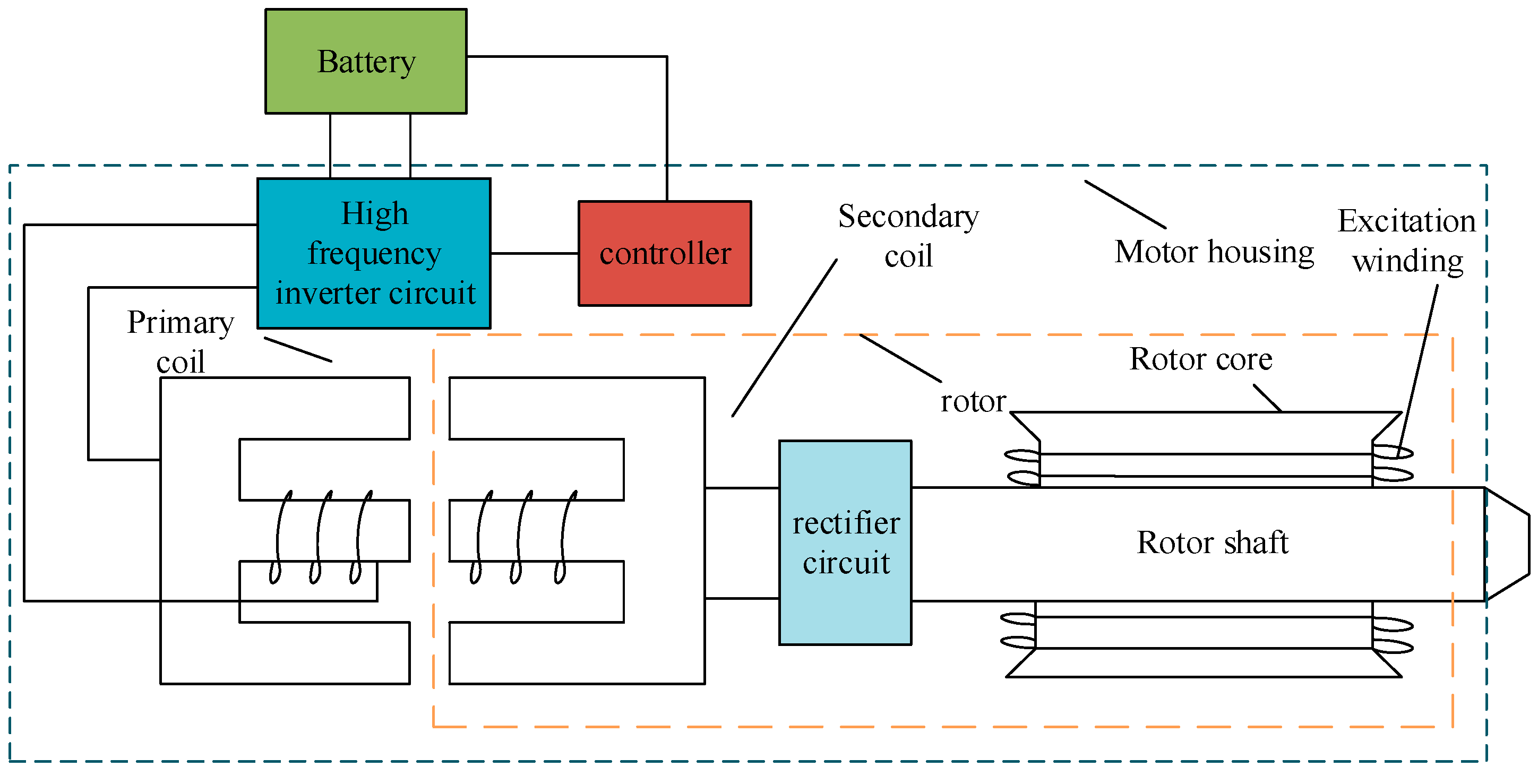
2.1. The Working Principle of Non-Contact Excitation Motor

Conventional electrically excited motors are excited by brushes and slip rings. On some special occasions, the wear of the meetings will produce carbon powder and cause damage to the electrical equipment. To this end, a new motor excitation method is proposed, which transfers energy through electromagnetic coupling, replacing traditional brushes and slip rings, making the motor run more safely and environmentally friendly. As shown in Figure 1, the motor’s structure, the motor’s stator, has a primary coil, and the rotor has a secondary coil. The DC power supply provides DC power, transmits the DC power to the full-bridge inverter module, and converts the DC power to AC power. The primary coil resonates, and the parameters of the primary coil are equal to the resonant frequency of the second wave. The primary coil transfers energy to the secondary coil without contact, and the secondary coil also resonates. The alternating current generated in the secondary coil continues to be connected to the full-bridge rectifier module. After the full-bridge rectifier module, since the stability of the output voltage needs to be controlled after the full-bridge rectifier circuit, the DC circuit conversion link should be added. Therefore, the BUCK circuit is added to stabilize the output voltage.
The system assembly diagram is shown in Figure 2: one is the transmitter subsystem, and the other is the receiver subsystem. The sending system is mounted on the stator and remains stationary during motor operation, while the receiving subsystem rotates with the motor rotor [43]. The size of the interval between the transmitter coil and the receiver coil will affect the transmission efficiency of the motor, so it is necessary to ensure that the size between the transmitter coil and the receiver coil is 2 mm.

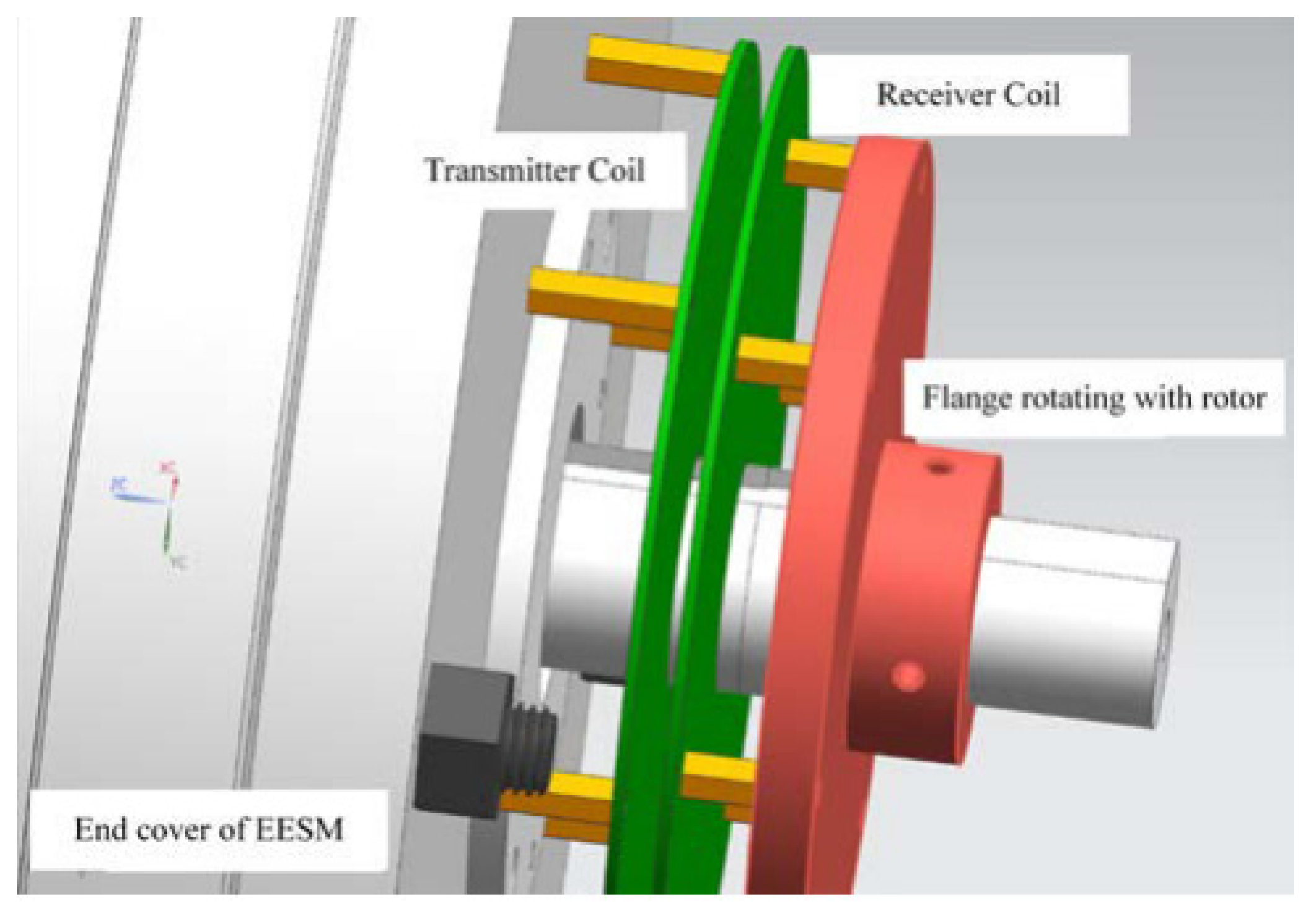
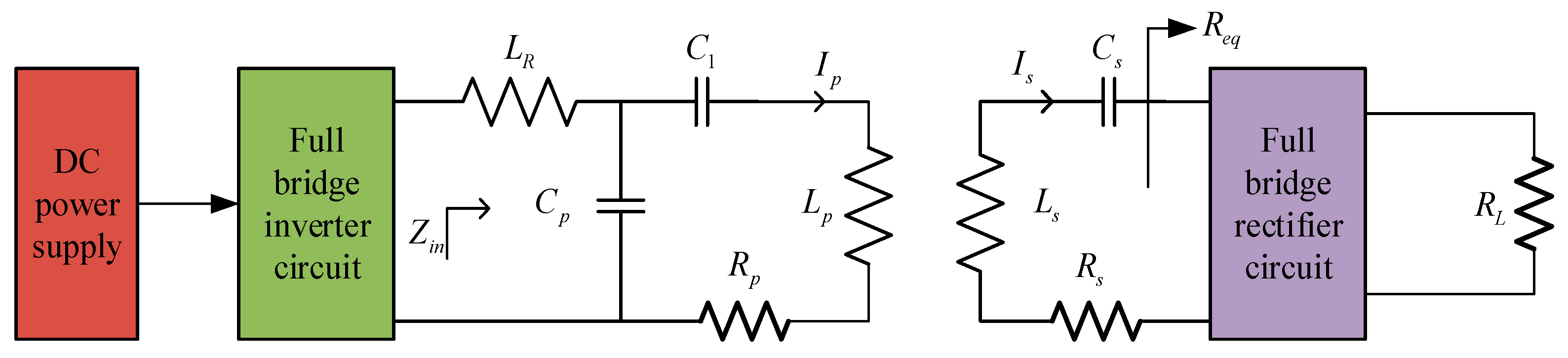
2.2. Analysis of Electromagnetic Coupling Device

As shown in Figure 3, the structure of the porcelain tank transformer. A magnetic slot transformer is a rotatable and separable transformer. When the primary side or the secondary side rotates relatively, the other side will not be affected so that the entire transformer can still transmit energy typically. Due to the structural characteristics of the porcelain tank transformer, slot transformers have good electromagnetic compatibility, shielding, and interchangeability. In addition, the slot transformer also has the advantages of a significant positive electrode area, small leakage inductance and distributed capacitance, high inductance per unit space, and convenient installation. The slot loosely coupled transformer used in the high-frequency transformer of this system is the core component of the rotor excitation system of the contactless synchronous motor.

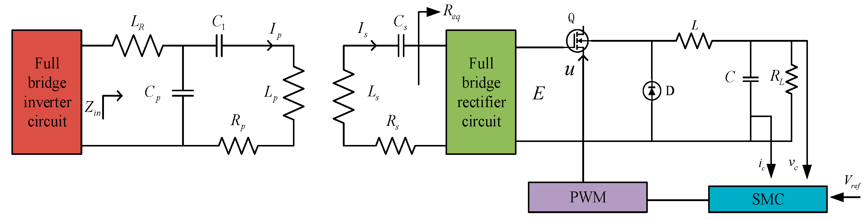
3. System Topology and Principle

Since the inductance in the primary coil will consume reactive power when resonance occurs, thereby reducing the transmission performance of the system, a compensation circuit needs to be added to compensate for the reactive power. Standard compensation circuits include series circuits and parallel circuits, adding a series circuit or similar to the primary side circuit, and adding a series circuit and a secondary side circuit to the secondary side circuit.
This compensation method has a simple structure, and the output current and voltage are easy to calculate, but this has many shortcomings in the actual application process. As the load increases, so does the wind in the primary coil, causing more unnecessary losses and making the components more prone to burnout. Based on this, we adopt a high-order compensation method. The primary side uses a compensation circuit that combines inductance and capacitance. The compensation circuit of the secondary side is still a series capacitor. It is found through a calculation that the current in the primary coil is completely independent of the system load. The circuit model and calculation process are explained in detail below.
The main circuit structure of the contactless excitation synchronous motor includes the following modules. The circuit topology is shown in Figure 4. The primary circuit consists of inductance LR, inductance LP, capacitors C1, CP, and resistance RP, in which inductance LR and capacitor CP form a resonant loop, and inductance LP, capacitor C1, and capacitor CP form a resonant loop. At this time, the resonant frequencies of the two loops are equal. The secondary circuit includes inductance IS, resistance RS, and capacitance CS. At this time, inductance LS, and capacitance form a resonant circuit. The secondary circuit includes inductance IS, resistance RS, and capacitance CS. At this time, inductance IS and capacitance CS form a resonant circuit. When the resonant frequencies of the three courses are equal, electromagnetic resonance occurs in the circuit, and the energy in the primary circuit will be transmitted to the secondary circuit through electromagnetic resonance. The primary coil and the secondary coil transmit power through electromagnetic coupling. The brush on the traditional motor is banned, the wear of the meeting is avoided, and the motor works more stably.
Req is the equivalent resistance after full-bridge rectification, ignoring the loss of the rectifier. In the primary circuit, there are two resonant circuits, which are the resonant circuit composed of the inductor.
Inductance LR and capacitor CP form the first resonant circuit. The other resonant circuit is where inductor LP connects with capacitor C1 and then resonates with CP. The primary coil has two resonant circuits: In the secondary coil, capacitor CS and inductor LS form a resonant circuit, and the primary coil and the secondary coil resonate to meet the above frequency requirements. Therefore, capacitance and inductance, respectively, satisfy the following mathematical relationships:
ω L R = 1 ω C P
ω L P 1 ω C 1 = 1 ω C P
ω L S = 1 ω C S
According to the above relationship between capacitance and inductance, resonance occurs in the circuit, and the energy in the primary coil can be transferred to the secondary coil through electromagnetic resonance. The equivalent impedance of the secondary circuit can be expressed as
Z S = R e q + R S + j ω L S + 1 j ω C S
where Zr is the reflected impedance of the secondary side circuit to the primary side.
Z r = ( ω M ) 2 Z S
During resonance, Zr and Zs are substituted as follows; the fundamental part of the equivalent impedance of the primary side is
R e ( Z i n ) = ω 2 L R 2 R P + Z r
where Uin is the input voltage of the primary coil. From the above equation, it can be concluded that the current through inductor LR can be expressed as the ratio of the input voltage to the input impedance as follows:
I R = U i n Z i n = ( R P + Z r ) U i n ω 2 L R 2
According to the parallel shunt principle, the current through inductor LP is calculated as follows:
I P = U i n j ω L p
According to the above analysis and calculation, the primary side adopts the LCC compensation method, and the current of the primary side inductance LP is only related to ω and Uin. Compared with the traditional series–parallel circuit, the change in the secondary side will not affect the current of the primary side circuit, and the anti-interference is better. Therefore, although the compensation circuit is more complex in this system, the primary side circuit is relatively stable and is not limited by the secondary side parameters. The following studies will employ this higher-order compensation method.

4. Comparison of Traditional Sliding Mode Control and Improved Sliding Mode Control

4.1. Traditional Sliding Mode Control

For some occasions that require a constant voltage power supply, the system resonance compensation network can meet the demand of the secondary side steady voltage power supply without changing the operating frequency and structure of the system. During the working process of the non-contact excitation motor, it is usually necessary to apply a stable voltage across RL. However, when the rotor is excited by the wireless energy transmission structure, the size of the equivalent load will also change with the change in the speed, so it must be ensured that the output voltage of the non-contact excitation motor is stable. To ensure the stability of the output voltage, a closed-loop control link must be added to the original buck circuit. In the electronic power transformation, the sliding mode control algorithm is often used to stabilize the output voltage, so on this basis, the sliding mode control and buck transformation are used.
As shown in Figure 5, the full-bridge rectifier circuit is followed by a BUCK circuit, a schematic diagram of a buck converter circuit. First, according to the working principle of the buck converter, a continuous conduction mode is designed in this system. The following state equations are listed according to whether the switch is turned on or off. When the PWM drive circuit drives the switch Q to conduct, that is, the switch state u = 1, the charge is transferred to the inductor L in the course under the action of the DC voltage E, and D is in the cut-off state under the movement of the reverse voltage. Currently, the differential equation for a buck converter is
[ d i L d t d v c d t ] = [ 1 L 0 1 R 1 C ] [ v c i L ] + [ E L 0 ]
When the switching state u = 0, the switch tube is turned off. At this time, the DC power input cannot act on the circuit, diode D is in the state under the action of forwarding voltage, and the energy absorbed by inductance L when the switch tube is turned on is transferred to resistance R. At this time, the differential equation of buck converter is
[ d i L d t d v C d t ] = [ 1 L 0 1 R 1 C ] [ v C i L ]

4.2. Improved Sliding Mode Control

As shown in Figure 6, traditional sliding mode control is often used in circuit transformation. Compared with PI adjustment, the adjustment time of sliding mode control is shorter, and there is no overshoot. However, traditional sliding mode control can no longer meet the actual conditions, increasing control accuracy and robustness requirements. Therefore, to improve the convergence speed and robustness of the current, conventional sliding mode control should be used.
Through the state space method, the state equation of the buck circuit is derived. The traditional sliding mode control has many shortcomings, so the improved sliding mode control method is adopted. Two variables are designed in the system, in which the output voltage is set to x1, and x2 is the derivative of the output voltage, which is expressed with the following formula:
x 1 = v c
x 2 = x ˙ 1 = d v c d t = 1 c i c = 1 c ( i L v c R )
According to Equations (11) and (12), it can be calculated
i L = u E v c L d t
x 2 = x ˙ 1 = u E v c L C v c R C d t
Further, the derivative operation is performed on Equation (14) to obtain the derivative of x2.
x ˙ 2 = v c L C 1 R C d v c d t + u E L C = 1 L C x 1 1 R C x 2 + E L C u
In summary, at this time, the state equation of the system can be expressed as
{ x ˙ 1 = x 2 x ˙ 2 = 1 L C x 1 1 R C x 2 + E L C u
where T is the sampling period, using the discrete rules, the state equation is rewritten as
{ x 1 , k + 1 = x 1 , k + T x 2 , k x 2 , k + 1 = x 2 , k T L C x 1 , k T R C x 2 , k + E T L C u k
To facilitate the subsequent calculation, the formula is transformed
M ( x k ) = x 2 , k T L C x 1 , k T R C x 2 , k , N ( x k ) = E T L C
After the above formulas are replaced, the state equation of the system is more concise and convenient. At this time, the new state equation is
{ x 1 , k + 1 = x 1 , k + T x 2 , k x 2 , k + 1 = M ( x k ) + N ( x k ) u k
In the sliding mode control algorithm, the algorithm of the sliding mode surface is a core process, and a new sliding mode surface is designed at this time.
s k = h e 2 , k + α g ( e 1 , k 1 ) + β e 1 , k 1 q p
g ( e 1 , k 1 ) = { g 1 ( e 1 , k 1 ) , i f | e 1 , k 1 | 1 g 2 ( e 1 , k 1 ) , i f | e 1 , k 1 | > 1
g ( e 1 , k 1 ) = { g 1 ( e 1 , k 1 ) = b sgn e 1 , k 1 log a ( 2 c | e 1 , k 1 | e 1 , k 1 2 + 1 ) g 2 ( e 1 , k 1 ) = g 1 ( sgn e 1 , k 1 ) + ( e 1 , k 1 sgn e 1 , k 1 ) h g
According to Equations (20) and (21), we can obtain
s k + 1 = h e 2 , k + 1 + α g ( e 1 , k ) + β e 1 , k q p
s k + 1 = h ( r 2 , k + 1 ( M ( x k ) + N ( x k ) u k ) ) + α g ( e 1 , k ) + β e 1 , k q p
g ( e 1 , k ) = { b sgn e 1 , k log a ( 2 c | e 1 , k | ( e 1 , k 2 + 1 ) ) , i f | e 1 , k | 1 g 1 ( sgn e 1 , k ) + ( e 1 , k sgn e 1 , k ) h g , i f | e 1 , k | > 1
In the above formula, e1 is the output voltage tracking error, and e2 is the current tracking error of the capacitor.
To make the system state quickly reach the PFDTSMC sliding mode surface in a limited time, the exponential reaching law was chosen.
s k + 1 = s k ε T sgn ( s k ) λ T s k
According to the above approach rate, an improved sliding mode control law is designed as
u k = r 2 , k + 1 M ( x k ) N ( x k ) + 1 h N ( x k ) ( α g ( e 1 , k ) + β ( e 1 , k ) q p ) 1 m N ( x k ) ( s k ε T sgn ( s k ) λ T s )
After the above analysis and calculation, when 0 < UK < 1,
u k = u k
When UK > 1 or UK < 0,
u k = 0.5 + 0.5 u k | u k |
The following proves the stability of the system, using Lyapunov stability theory to analyze. The chosen Lyapunov function is
V k = 1 2 s k 2
The system can be stable if and only if the Lyapunov function satisfies the following conditions:
Δ V k = s k + 1 2 s k 2 < 0 ,   s k 0
According to the Lyapunov theorem, the states in any initial position will approach the sliding surface Sk. When T is sufficiently small, the existing and reaching conditions of the discrete-time sliding mode can be expressed as follows:
{ ( s k + 1 s k ) sgn s k < 0 ( s k + 1 + s k ) sgn s k > 0
s k + 1 s k = h ( r 2 , k + 1 ( M ( x k ) + N ( x k ) u k ) ) + α g ( e 1 , k ) + β e 1 , k q p ( h e 2 , k + α g ( e 1 , k 1 ) + β e 1 , k 1 q p )
Substituting the control law (27) for PFDTSMC into Equation (33), we obtain
( s k + 1 s k ) sgn s k = λ T | s k | ε T | s k | < 0
When the sampling period T is sufficiently small, we obtain the conclusion of 2 − λT >> 0. Therefore,
( s k + 1 + s k ) sgn s k = ( 2 λ T ) | s k | ε T | s k | > 0
As can be seen from Equations (34) and (35) above, the improved control law satisfies the stability condition of Equation (32). Therefore, the stability of the system is proved by derivation.

5. Simulated Analysis

To test the applicability of the controller, the simulation software MATLAB is used to simulate and compare the traditional sliding mode control and power fast discrete terminal sliding mode control methods. Compare how fast the output voltage stabilizes. The effects of improved sliding mode control and traditional sliding mode control in stabilizing the output voltage of the non-contact excitation motor are discussed in the following three working conditions. The system parameters are shown in the Table 1 below.

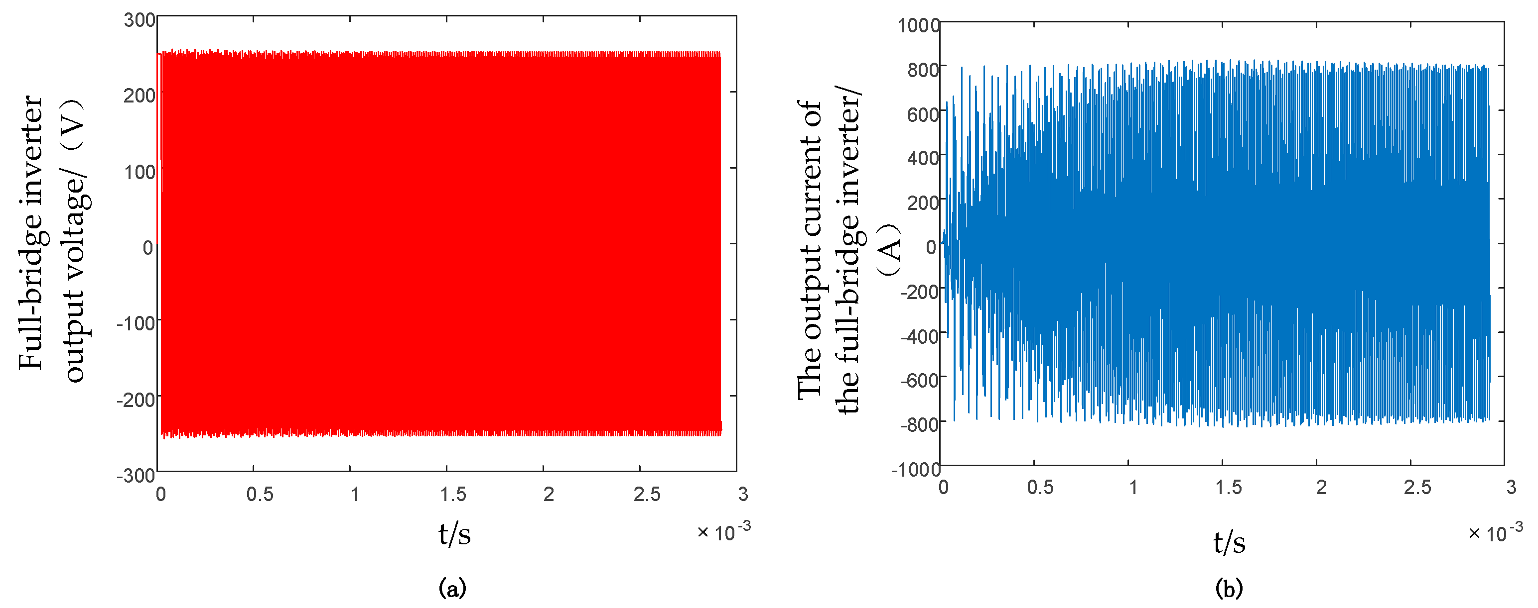
5.1. Voltage and Current Output by the Full-Bridge Inverter Circuit

In electromagnetic resonance, alternating current needs to be used to transmit energy, so it is necessary to add a full-bridge inverter circuit after direct current to convert direct current into alternating current.
As shown in Figure 7, it is a voltage simulation diagram output by the resonant circuit. After stabilization, the output voltage amplitude is 245 V, and the output voltage and current are both AC. Then, as seen in Figure 7b, the output current is approximately sinusoidal alternating current, and the amplitude of the wind is 800 A.

5.2. Voltage and Current Output from Resonant Circuit

When the full-bridge inverter circuit converts the direct current into alternating current, it is connected to the resonant circuit, and the primary circuit and the secondary circuit can transfer energy through electromagnetic coupling.
As shown in Figure 8, it is a voltage simulation diagram output by the resonant circuit. After stabilization, the output voltage amplitude is 225 V, and the output voltage and current are both AC. By observing Figure 8b, it is evident that after the output current is stable, the current is sinusoidal alternating current, and the current amplitude is 600 A. It can be seen that the waveforms of voltage and current have ripples, so it is necessary to continue to add conversion circuits to reduce the waves. In short, after a series of transformations, the direct current is converted into alternating current through the full-bridge inverter and then through electromagnetic coupling to achieve non-contact energy transmission, which avoids the wear of the brushes inside the original motor, and significantly prolongs the life of the motor.

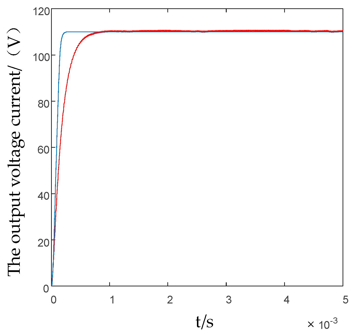
5.3. Output Voltage Stability Comparison for Stable Loads

In the following, first, the difference between the two algorithms in stabilizing voltage and current when the load is constant is analyzed. The non-contact excitation motor can adapt to various working conditions and meet the actual requirements.
According to Figure 9, we can compare the simulation graphs of the output voltage under the two algorithms. The red line represents the result of the system output voltage under the traditional sliding mode control: the output voltage is stable at 110 V, and the stabilization time is 0.001 s. The blue line shows the result of the output voltage under the improved sliding mode control; it can be seen that in the simulated waveform of the improved sliding mode control, the output voltage is finally stabilized at 110 V. Compared with traditional sliding mode control, the settling time is faster, which is 0.0005 s, and the time to reach stability is 50% faster. By comparing the simulation diagram of the output voltage and the time required for the output voltage to stabilize under the control of the two algorithms, it can be seen that the improved sliding mode control has obvious advantages, compared with the traditional sliding mode control. The overshoot is also more minor.

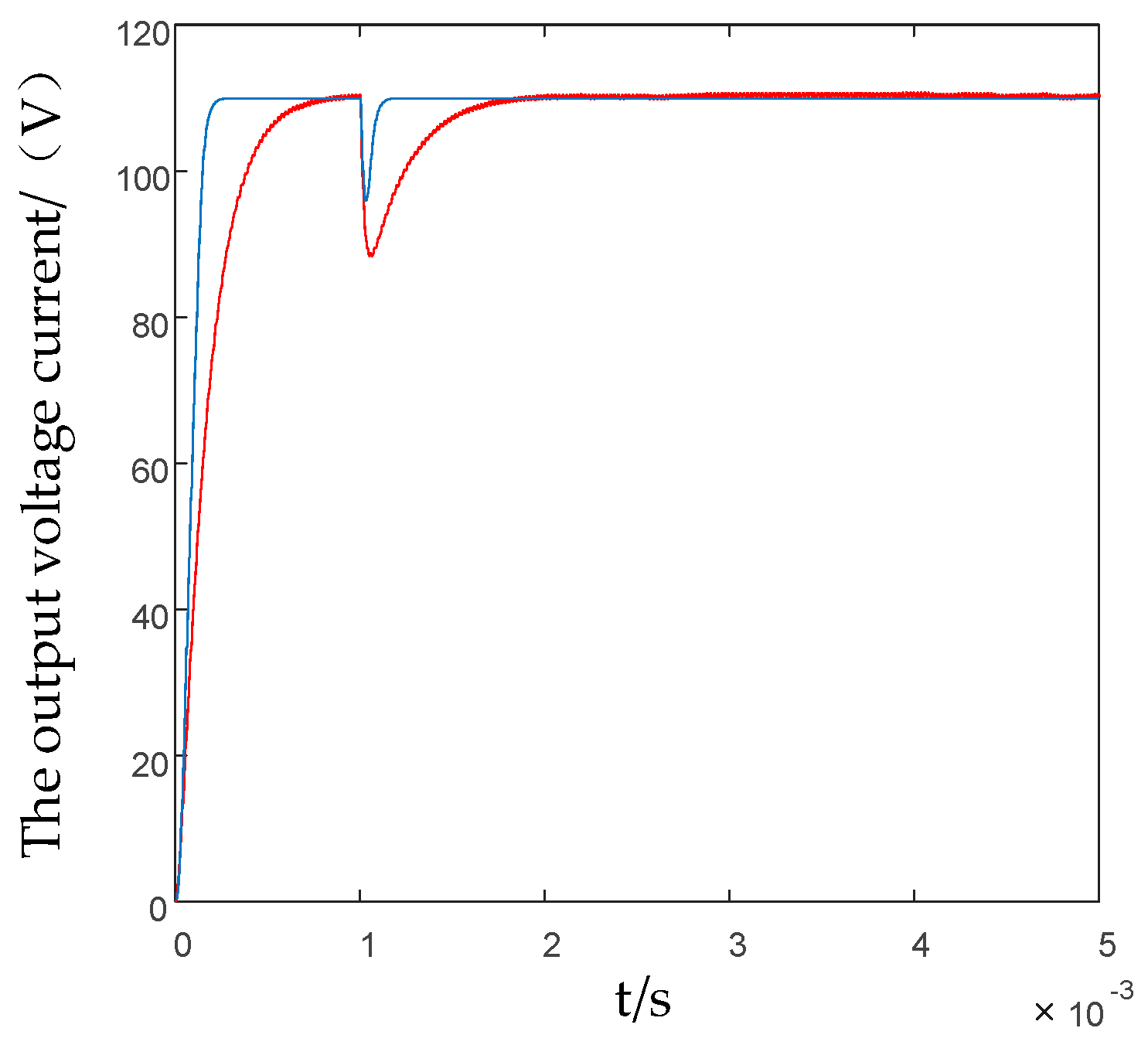
5.4. Output Voltage Stability Comparison of Variable Loads

In the actual wireless energy transmission system, the load is not constant and sometimes changes, which requires real-time adjustment of the closed-loop system structure to keep the output voltage and output current stable within a specific load variation range.
According to Figure 10, the output voltage suddenly changes when the system is disturbed by the load for 0.001 s. Due to the closed-loop regulation in the system, the output voltage can still be maintained at 110 V. The red line represents the result of the system output voltage under traditional sliding mode control, and it can be seen that the overshoot of the output voltage is 30 V. The blue line shows the result of the output voltage under the improved sliding mode control, where the load is subjected to the same disturbance at 0.01 s; it can be seen that the output voltage overshoots, and compared with the conventional sliding mode control, the amount is more minor; the overshoot is 25 V, the time to stabilize is also shorter, and the adjustment time is 0.0002 s. Compared with the traditional sliding mode control, the adjustment time is five times faster, so the improved sliding mode control algorithm is more suitable for complicated situations.

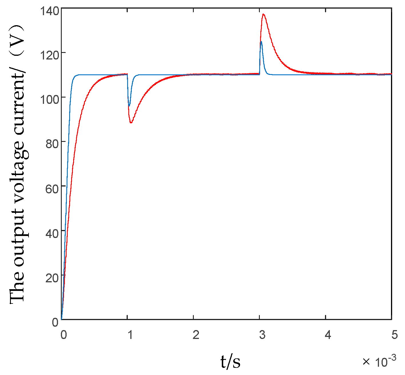
5.5. Comparison of Output Voltage Stability under Variable Load for Two Consecutive Times

To enable the system to meet more complex conditions, the load was changed at 0.001 s and 0.003 s, respectively. The differences in stable output voltage and output current between the traditional sliding mode control and the improved sliding mode control are observed.
According to the simulation results of the output voltage in Figure 11, both algorithms need a certain amount of time to stabilize the output voltage when the load is changed twice in a row, and the output voltage has a certain amount of overshoot. Specifically, the red line represents the result of the output voltage when the load changes twice in a row under traditional sliding mode control. After the first load change, the output voltage has a sudden change, which takes 0.001 s to stabilize, and the output voltage overshoot is 20 V. On the second load change, it takes 0.0005 s to stabilize. The output voltage overshoot is 25 V. The blue line shows the result of the output voltage under improved sliding mode control. At the first load change, it takes 0.0005 s for the output voltage to stabilize, which is two times faster than the traditional sliding mode control, and the voltage overshoot is 15 V. The second load change takes 0.00025 s to stabilize, and the voltage overshoot is 20 V, which is smaller than the traditional sliding mode control. Therefore, the improved sliding mode control has a shorter adjustment time and an overshoot when the load changes continuously. The volume is smaller, and the efficiency is higher.

6. Conclusions

In this paper, we focused on the non-contact excitation method of the electric excitation motor and deduced the optimal reactive power compensation of the primary and secondary sides of the non-contact excitation motor. Finally, an improved sliding mode control algorithm was introduced to control the motor’s voltage output. The advantages and disadvantages of the traditional sliding mode control and the improved sliding mode control in stabilizing the output voltage were introduced in detail. Finally, after the above theoretical analysis and mathematical derivation, the feasibility and accuracy of the proposed method were verified through a series of simulations and experiments. The simulation and experimental results show that the improved sliding mode control algorithm has a better effect on stabilizing the output voltage of the non-contact electric excitation motor.

Author Contributions

Conceptualization, K.L.; writing—review and editing, K.L. and X.M.; supervision, X.S. All authors have read and agreed to the published version of the manuscript.

Funding

This study was funded by the National Natural Science Foundation of China under Project 52002155.

Institutional Review Board Statement

Not applicable.

Informed Consent Statement

Not applicable.

Data Availability Statement

Data are contained within the article.

Conflicts of Interest

The authors declare no conflict of interest.

References

  1. Chen, L.; Xu, H.; Sun, X. A novel strategy of control performance improvement for six-phase permanent magnet synchronous hub motor drives of EVs under new European driving cycle. IEEE Trans. Veh. Technol. 2021, 70, 5628–5637. [Google Scholar] [CrossRef]
  2. Suhail, M.; Akhtar, I.; Kirmani, S. Development of Progressive Fuzzy Logic and ANFIS Control for Energy Management of Plug-In Hybrid Electric Vehicle. IEEE Access 2021, 9, 62219–62231. [Google Scholar] [CrossRef]
  3. Mahdavian, A.; Shojaei, A.; Mccormick, S. Drivers and Barriers to Implementation of Connected, Automated, Shared, and Electric Vehicles: An Agenda for Future Research. IEEE Access 2021, 9, 22195–22213. [Google Scholar] [CrossRef]
  4. Sun, X.; Shi, Z.; Cai, Y.; Lei, G.; Guo, Y.; Zhu, J. Driving-cycle design optimization of a permanent magnet hub motor drive system for a four-wheel-drive electric vehicle. IEEE Trans. Transp. Electrif. 2020, 6, 1115–1125. [Google Scholar] [CrossRef]
  5. Diao, K.; Sun, X.; Lei, G.; Guo, Y.; Zhu, J. Multiobjective system level-oriented optimization method for switched reluctance motor drive systems using finite element model. IEEE Trans. Ind. Electron. Electron. 2020, 67, 10055–10064. [Google Scholar] [CrossRef]
  6. Rezaei, A.; Burl, J.B.; Rezaei, M. Catch Energy Saving Opportunity in Charge-Depletion Mode, A Real-Time Controller For Plug-in Hybrid Electric Vehicles. IEEE Trans. Veh. Technol. 2018, 67, 11234–11237. [Google Scholar] [CrossRef]
  7. Yilmaz, M.; Krein, P.T. Review of Battery Charger Topologies, Charging Power Levels, and Infrastructure for Plug-In Electric and Hybrid Vehicles. IEEE Trans. Power Electron. 2013, 28, 2151–2169. [Google Scholar] [CrossRef]
  8. Chen, L.; Xu, H.; Sun, X.; Cai, Y. Three-vector-based model predictive torque control for a permanent magnet synchronous motor of EVs. IEEE Trans. Transp. Electrif. 2021, 7, 1454–1465. [Google Scholar] [CrossRef]
  9. Karttunen, J.; Kallio, S.; Honkanen, J.; Peltoniemi, P.; Silventoinen, P. Partial Current Harmonic Compensation in Dual Three-Phase PMSMs Considering the Limited Available Voltage. IEEE Trans. Ind. Electron. 2017, 64, 1038–1048. [Google Scholar] [CrossRef]
  10. Sun, X.; Chen, L.; Jiang, H.; Yang, Z.; Chen, J.; Zhang, W. High-performance control for a bearingless permanent magnet synchronous motor using neural network inverse scheme plus internal model controllers. IEEE Trans. Ind. Electron. 2016, 63, 3479–3488. [Google Scholar] [CrossRef]
  11. Jin, Z.; Sun, X.; Lei, G.; Guo, Y.; Zhu, J. Sliding mode direct torque control of SPMSMs based on a hybrid wolf optimization algorithm. IEEE Trans. Ind. Electron. 2022, 69, 4534–4544. [Google Scholar] [CrossRef]
  12. Kou, J.; Gao, Q.; Sha, Z.; Teng, Y.; Xu, D. A rotor position detection method at high speed for electrically excited synchronous motor. In Proceedings of the 2019 22nd International Conference on Electrical Machines and Systems (ICEMS), Harbin, China, 11–14 August 2019; pp. 1–5. [Google Scholar]
  13. Sulaiman, E.; Kosaka, T.; Matsui, N. High Power Density Design of 6-Slot–8-Pole Hybrid Excitation Flux Switching Machine for Hybrid Electric Vehicles. IEEE Trans. Magn. 2011, 47, 4453–4456. [Google Scholar] [CrossRef]
  14. Han, Y.; Wu, X.; He, G.; Hu, Y.; Ni, K. Nonlinear Magnetic Field Vector Control with Dynamic-Variant Parameters for High-Power Electrically Excited Synchronous Motor. IEEE Trans. Power Electron. 2020, 35, 11053–11063. [Google Scholar] [CrossRef]
  15. Alarifi, I.M.; Asmatulu, R. Structural analysis and wear behavior of different graphite-based brushes for aircraft starter generator application. Adv. Compos. Hybrid Mater. 2021, 4, 162–172. [Google Scholar]
  16. Nozawa, R.; Kobayashi, R.; Tanifuji, H. Excitation system by contactless power transfer system with the primary series capacitor method. In Proceedings of the Power Electronics Conference, Hiroshima, Japan, 16–20 March 2014; Volume 21, pp. 1115–1121. [Google Scholar]
  17. Duong, T.P.; Lee, J.W. Experimental Results of High-Efficiency Resonant Coupling Wireless Power Transfer Using a Variable Coupling Method. IEEE Microw. Wirel. Compon. Lett. 2011, 21, 442–444. [Google Scholar] [CrossRef]
  18. Raminosoa, T.; Wiles, R.H.; Wilkins, J. Novel Rotary Transformer Topology with Improved Power Transfer Capability for High-Speed Applications. IEEE Trans. Ind. Appl. 2020, 56, 277–286. [Google Scholar] [CrossRef]
  19. Ardila, V.; Ramírez, F.; Suárez, A. Nonlinear Analysis of a High-Power Oscillator Inductively Coupled to an External Resonator. IEEE Microw. Wirel. Compon. Lett. 2021, 31, 737–740. [Google Scholar] [CrossRef]
  20. Sun, X.; Diao, K.; Lei, G.; Guo, Y.; Zhu, J. Real-time HIL emulation for a segmented-rotor switched reluctance motor using a new magnetic equivalent circuit. IEEE Trans. Power Electron. 2020, 35, 3841–3849. [Google Scholar] [CrossRef]
  21. Fu, M.; Tang, Z.; Ma, C. Analysis and Optimized Design of Compensation Capacitors for A Megahertz WPT System Using Full-Bridge Rectifier. IEEE Trans Ind. Inf. 2018, 15, 95–104. [Google Scholar] [CrossRef]
  22. Janson, K.; Jarvik, J. AC-DC converter with parametric reactive power compensation. IEEE Trans. Ind. Electron. 1999, 46, 554–562. [Google Scholar] [CrossRef]
  23. Yi, J.; Wei, H. Steady-state voltage reactive compensation method for half-wavelength transmission lines considering equivalent power supply impedance. CSEE J. Power Energy Syst. 2020, 6, 841–847. [Google Scholar]
  24. Wu, J.; Sun, P.W.X. Reactive Power Optimization Control for Bidirectional Dual-Tank Resonant DC-DC Converters for Fuel Cells Systems. IEEE Trans. Power Electron. 2020, 35, 9202–9214. [Google Scholar] [CrossRef]
  25. Chen, L.; Wang, H.; Sun, X.; Cai, Y.; Li, K.; Diao, K.; Wu, J. Development of digital control system for a belt-driven starter generator SSRM for HEVs. Proc. Inst. Mech. Eng. Part I J. Syst. Control Eng. 2020, 234, 975–984. [Google Scholar]
  26. Zheng, C.; Dragičević, T.; Zhang, J.; Chen, R.; Blaabjerg, F. Composite Robust Quasi-Sliding Mode Control of DC-DC Buck Converter with Constant Power Loads. IEEE Trans. Emerg. Sel. Top. Power Electron. 2020, 9, 1455–1464. [Google Scholar] [CrossRef]
  27. Wu, H.; Mu, T.; Ge, H.; Xing, Y. Full-Range Soft-Switching-Isolated Buck-Boost Converters with Integrated Interleaved Boost Converter and Phase-Shifted Control. IEEE Trans. Power Electron. 2015, 31, 987–999. [Google Scholar] [CrossRef]
  28. Naik, B.S.; Suresh, Y.; Venkataramanaiah, J. A Hybrid Nine-Level Inverter Topology with Boosting Capability and Reduced Component Count. IEEE Trans. 2020, 68, 316–320. [Google Scholar] [CrossRef]
  29. Rana, N.; Banerjee, S.; Giri, S.K. Modeling, Analysis and Implementation of an Improved Interleaved Buck-Boost Converter. IEEE Trans. Circuits Syst. II: Express Briefs 2021, 68, 2588–2592. [Google Scholar] [CrossRef]
  30. Al-Baidhani, H.; Salvatierra, T.; Ordonez, R. Simplified Nonlinear Voltage-Mode Control of PWM DC-DC Buck Converter. IEEE Trans. Energy Convers. 2020, 36, 431–440. [Google Scholar] [CrossRef]
  31. Kolluri, S.; Narasamma, N.L. A New Isolated Auxiliary Current Pump Module for Load Transient Mitigation of Isolated/No isolated Step-Up/Step-Down DC-DC Converter. IEEE Trans. Power Electron. 2015, 30, 5991–6000. [Google Scholar] [CrossRef]
  32. Hou, N.; Song, W.; Zhu, Y. Dynamic and static performance optimization of dual active bridge DC-DC converters. J. Mod. Power Syst. Clean Energy 2018, 6, 607–618. [Google Scholar] [CrossRef] [Green Version]
  33. Fu, Z.; Wang, Y.; Tao, F.; Si, P. An Adaptive Nonsingular Terminal Sliding Mode Control for Bidirectional DC-DC Converter in Hybrid Energy Storage Systems. Can. J. Electr. Comput. Eng. 2020, 43, 282–289. [Google Scholar] [CrossRef]
  34. Xu, J.; Sun, Y.; Xu, G. Current Fed LC Series Resonant Converter with Load Independent Voltage Gain Characteristics for Wide Voltage Range Applications. IEEE Trans. Power Electron. 2021, 36, 11509–11522. [Google Scholar] [CrossRef]
  35. Xu, Y.; Lu, C.; Yu, Z.; Chen, J.; Xu, S.; Wang, Y.; He, X. Multi-mode Constant Power Control Strategy for LCC Resonant Capacitor Charging Power Supply Based on State Plane Analysis. IEEE Trans. Power Electron. 2020, 36, 8399–8412. [Google Scholar] [CrossRef]
  36. Sun, X.; Cao, J.; Lei, G.; Guo, Y.; Zhu, J. A robust deadbeat predictive controller with delay compensation based on composite sliding mode observer for PMSMs. IEEE Trans. Power Electron. 2021, 36, 10742–10752. [Google Scholar] [CrossRef]
  37. Wang, Y.; Zhang, H.; Lu, F. Capacitive Power Transfer with Series-Parallel Compensation for Step-Up Voltage Output. IEEE Trans. Ind. Electron. 2021, 69, 5604–5614. [Google Scholar] [CrossRef]
  38. Sun, X.; Wu, J.; Lei, G.; Guo, Y.; Zhu, J. Torque ripple reduction of SRM drive using improved direct torque control with sliding mode controller and observer. IEEE Trans. Ind. Electron. 2021, 68, 9334–9345. [Google Scholar] [CrossRef]
  39. Sun, X.; Feng, L.; Diao, K.; Yang, Z. An improved direct instantaneous torque control based on adaptive terminal sliding mode for a segmented-rotor SRM. IEEE Trans. Ind. Electron. 2021, 68, 10569–10579. [Google Scholar] [CrossRef]
  40. Sun, X.; Cao, J.; Lei, G.; Guo, Y.; Zhu, J. A composite sliding mode control for SPMSM drives based on a new hybrid reaching law with disturbance compensation. IEEE Trans. Transp. Electrif. 2021, 7, 1427–1436. [Google Scholar] [CrossRef]
  41. Wang, Y.; Xu, J.; Qin, F. A Capacitor Current and Capacitor Voltage Ripple Controlled SIDO CCM Buck Converter with Wide Load Range and Reduced Cross Regulation. IEEE Trans. Ind. Electron. 2021, 69, 270–281. [Google Scholar] [CrossRef]
  42. Song, P.; Cui, C.; Bai, Y. Robust Output Voltage Regulation for DC-DC Buck Converters under Load Variations via Sampled-Data Sensorless Control. IEEE Access 2018, 66, 10688–10698. [Google Scholar] [CrossRef]
  43. Kang, J.; Liu, Y.; Sun, L. A Primary-Side Control Method of Wireless Power Transfer for Motor Electric Excitation. In Proceedings of the 2019 14th IEEE Conference on Industrial Electronics and Applications (ICIEA), Xi’an, China, 19–21 June 2019; Volume 32, pp. 2423–2428. [Google Scholar]
Figure 1. Structure diagram of contactless excitation motor.
Applsci 12 03666 g001
Figure 2. Assembly diagram of the contactless excitation system.
Applsci 12 03666 g002
Figure 3. Porcelain tank transformer structure.
Applsci 12 03666 g003
Figure 4. Circuit topology principle of contactless excitation motor.
Applsci 12 03666 g004
Figure 5. System topology with sliding mode control.
Applsci 12 03666 g005
Figure 6. Power type fast discrete terminal sliding mode control.
Applsci 12 03666 g006
Figure 7. Simulation diagram of the output of the full-bridge inverter circuit: (a) the voltage simulation diagram of the result of the full-bridge inverter circuit; (b) current simulation diagram of creating the full-bridge inverter circuit.
Applsci 12 03666 g007
Figure 8. Resonant circuit output simulation plot: (a) simulation of the voltage output from the resonant circuit; (b) simulation of the current output from the resonant circuit.
Applsci 12 03666 g008
Figure 9. Simulation plot of the output voltage under controlled load variation.
Applsci 12 03666 g009
Figure 10. Simulation plot of the output voltage under a single load change.
Applsci 12 03666 g010
Figure 11. Simulation plot of the output voltage under two successive load changes.
Applsci 12 03666 g011
Table 1. Non-contact excitation motor parameters.
SpecificationValueSpecificatinValue
LR (μH)20CS (nF)36
CP (nF)175RS (Ω)0.075
C1 (nF)45E (V)200
LP (μH)0.076L (μH)544
RP (Ω)0.075C (nF)8
LS (μH)0.075RL (Ω)3
Publisher’s Note: MDPI stays neutral with regard to jurisdictional claims in published maps and institutional affiliations.

