Article

Low-Frequency Low-Reflection Bidirectional Sound Insulation Tunnel with Ultrathin Lossy Metasurfaces

1
Research Center of Fluid Machinery Engineering and Technology, School of Physics and Electronic Engineering, Jiangsu University, Zhenjiang 212013, China
2
Key Laboratory of Modern Acoustics, National Laboratory of Solid State Microstructures, Department of Physics, Collaborative Innovation Center of Advanced Microstructures, Nanjing University, Nanjing 210093, China
3
State Key Laboratory of Acoustics, Institute of Acoustics, Chinese Academy of Sciences, Beijing 100190, China
*
Authors to whom correspondence should be addressed.
Appl. Sci. 2022, 12(7), 3470; https://doi.org/10.3390/app12073470
Submission received: 24 February 2022 / Revised: 24 March 2022 / Accepted: 26 March 2022 / Published: 29 March 2022
(This article belongs to the Special Issue Recent Advance in Acoustic Metamaterials)

Abstract

:
We report both numerical and experimental constructions of a tunnel structure with low-frequency low-reflection bidirectional sound insulation (BSI). The designed tunnel was constructed from a pair of lossy acoustic metasurfaces (AMs), which consists of six ultrathin coiled unit cells, attached on both sides. Based on the generalized Snell′s law and phase modulations for both AMs, the tunnel with the low-frequency BSI was constructed based on sound reflections and acoustic blind areas created by the AMs. The obtained transmittances were almost the same for sound incidences from both sides and were lower than −10 dB in the range 337–356 Hz. The simulated and measured results agreed well with each other. Additionally, we show that the low-reflection characteristic of the tunnel can be obtained simultaneously by thermoviscous energy loss in coiled channels of the unit cells. Finally, an interesting application of the designed tunnel in an open-window structure with low-frequency low-reflection BSI is further simulated in detail. The proposed tunnel based on the ultrathin lossy AMs has the advantages of ultrathin thickness (about λ/35), low-frequency low-reflection BSI, and high-performance ventilation, which may have potential applications in architectural acoustics and noise control.

1. Introduction

Low-frequency sound insulation has attracted more and more attention in the fields of acoustics and mechanical engineering due to its great potential in noise control, environmental protection and architectural acoustics. Generally, traditional porous and fibrous materials [1], and micro-perforated plates [2,3] have been used in sound insulation, but their thicknesses are close to the working wavelengths, resulting in a relatively large number of sound insulation structures in the low-frequency range and greatly limiting their further practical applications.
In the past few years, the rapid development of metamaterials [4,5,6,7,8,9,10,11,12,13] and metasurfaces [14,15,16,17,18,19,20,21,22] has provided alternative ways to design a variety of sound insulation or absorption systems that can overcome the limitations of these traditional materials. The previously demonstrated systems are mainly based on different types of unit cells, such as Helmholtz resonators designed to contain a resonant cavity with a narrow neck [23,24,25,26], membrane resonators composed of a fixed elastic film decorated with asymmetric rigid platelets [27], coherent perfect absorbers with specific complex mass density or bulk modulus [28,29], metasurface-based structures with a deep subwavelength [30,31,32,33,34], labyrinthine Fabry–Perot resonators with coiling channels [35,36] or split-ring resonators consisting of two reverse ellipse-shaped split tubes [37]. The systems designed by these types of unit cells have the advantages of subwavelength thickness and high-performance sound insulation or absorption. However, most of them have been designed to be closed, and it is therefore difficult to apply them to ventilation structures.
To overcome this, a variety of open structures with sound insulation or absorption based on different mechanisms have previously been proposed, including open sound barriers based on resonance coupling [38], coherent interference [39] and artificial Mie resonances [40], and ventilation tunnels based on Helmholtz resonances [41], destructive interference [42] and asymmetric multiple scatterings [43]. In these demonstrated structures, the sound insulation or absorption with ventilation can be shown theoretically and experimentally, but the relatively large thickness and narrow ventilation width restrict their practical applications.
Recently, a class of ultrathin structures called acoustic metasurfaces (AMs), which have sound modulation based on the generalized Snell′s law [44], have attracted more and more attention due to their wide potential application. By setting desired gradient–phase profiles, the AMs can be applied to the design of metacages [45], open tunnels [46] and windows [47,48], achieving sound insulation and ventilation simultaneously. However, the working bands of these structures are generally higher than 1000 Hz, and few of them are applied in the low-frequency region. Beyond that, the success of sound insulation is mainly determined by sound reflections created by the AMs, but in some practical scenarios, it is also necessary to create low reflection of sound through open structures. Thus, the design of low-frequency low-reflection open structures with sound insulation based on the sound modulations of AMs has become an urgent problem to be solved.
In this work, we propose a type of low-frequency low-reflection bidirectional sound insulation (BSI) tunnel, which is constructed from a pair of lossy AMs with six ultrathin coiled unit cells attached on both sides. Based on the generalized Snell′s law and phase modulations by both AMs, we achieved a low-frequency BSI in the tunnel, which arose from the sound reflections and acoustic blind areas created by the AMs. The low-frequency BSI of the tunnel existed in the range 337–356 Hz, and the simulated and measured results were consistent with each other. Additionally, we obtained the low-reflection feature of the tunnel based on thermoviscous energy loss in coiled channels of the unit cells. Finally, we present in detail an application of the designed tunnel in an open-window structure with low-frequency low-reflection BSI.
The work is organized as follows. In Section 2, a low-frequency ultrathin coiled unit cell is designed, and an ultrathin lossy AM with the phase gradient d φ / d x = k , based on the designed unit cells, is proposed. The theoretical propagation paths of reflected waves through the AM with different incident angles are also discussed. In Section 3, a type of open tunnel with a pair of AMs on both sides is designed and the low-frequency low-reflection BSI is obtained. In Section 4, the physical mechanism of the low-reflection BSI is exhibited. In Section 5, experimental measurements of the proposed open tunnel are presented. Section 6 shows an application of the designed tunnel in an open-window structure with low-frequency low-reflection BSI. Conclusions are displayed in Section 7.

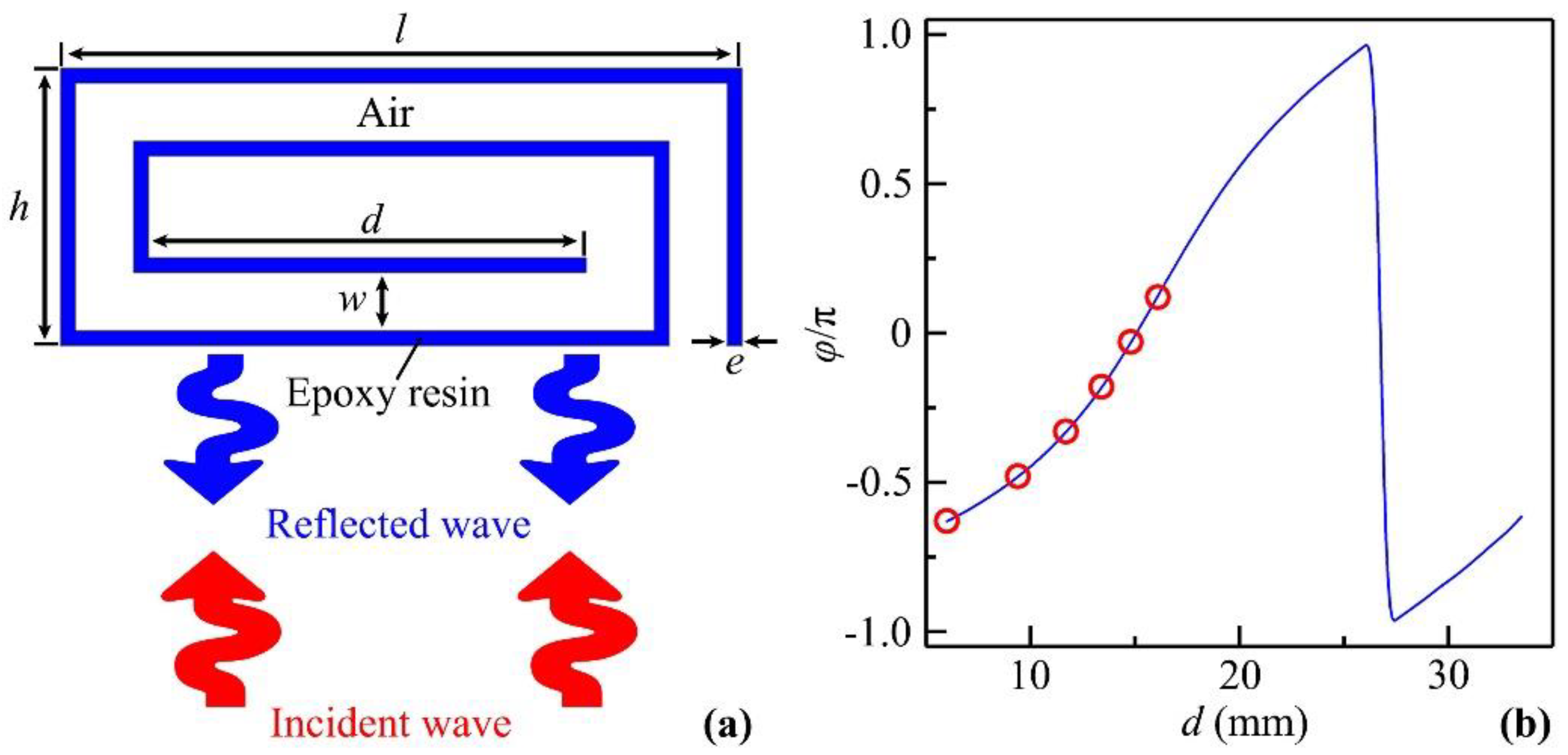
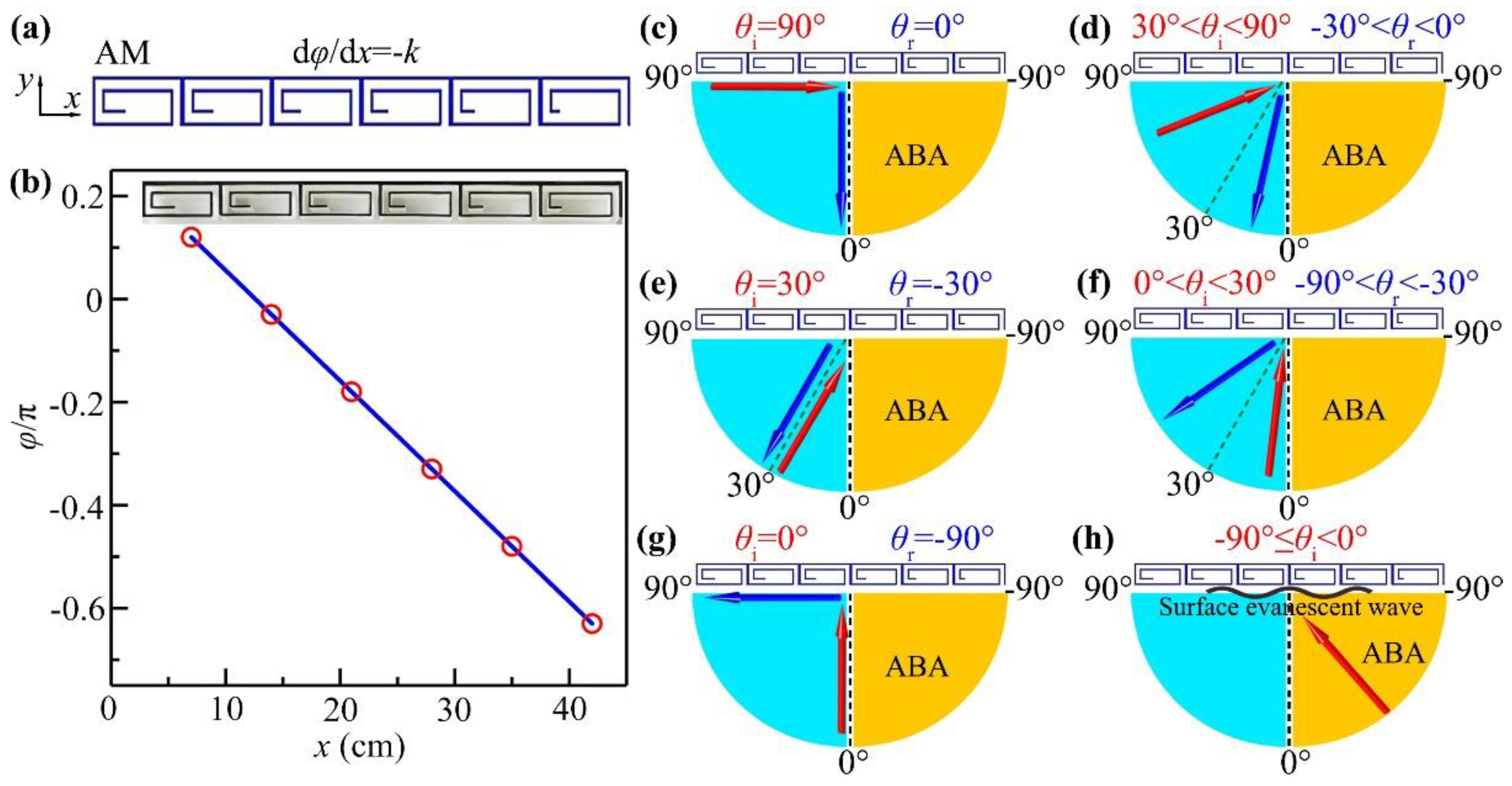
2. Design and Performance of Unit Cells and AMs

As schematically shown in Figure 1a, we propose a low-frequency ultrathin coiled unit cell that is made of epoxy resin. The parameters e, w, d, l and h represent the wall thickness, the channel width, the length of the horizontal inner plate, and the total length and thickness of the unit cell, respectively. The designed unit cell can reflect incident sound energy, leading to phase delay. Here, the parameters l, w, e and h are selected as 70.0 mm, 6.0 mm, 1.5 mm and 28.5 mm, respectively, and the parameter d is tunable, which means it can be used to modulate the reflected phase delay of the unit cell. Throughout this work, we use the software of COMSOL Multiphysics to numerically simulate low-frequency low-reflection BSI through the tunnel; the settings of numerical models are listed in Table 1. Additionally, the thickness of the thermoviscous acoustic boundary layer is d v = 2 μ / ρ ω [25], in which the parameters μ, ρ and ω are the coefficient of dynamic viscosity, the density of air and the angular frequency, respectively. The material parameters of epoxy resin and air in the numerical models are shown in Table 2. Figure 1b shows the reflected phase delays created by the unit cells with different values of d at 370 Hz. We can see that the reflected phase delay can cover almost the whole range of 2π by changing d, and therefore, a low-frequency reflected AM with an arbitrary phase profile can be constructed based on the proposed unit cell.
Figure 2a shows the designed AM composed of six unit cells, in which the values of d are selected as 16.1 mm, 14.8 mm, 13.4 mm, 11.7 mm, 9.4 mm, and 6.0 mm for the unit cells from left to right. The phase gradient d φ / d x = k , where k = 2π/λ, is the wave number in air, and λ is the wavelength. The theoretical continuous and discrete phase delays of the AM are shown in Figure 2b, and the photograph of the AM fabricated with epoxy resin based on a 3D printing technology is exhibited in the upper inset. The AM can modulate the phase delay of reflected waves based on its phase gradient. Based on the generalized Snell′s law [44], the relationship between the incident angle θi and the reflected angle θr created by the AM is expressed as
sin θ r = sin θ i + 1 k d φ d x ,
in which θi and θr are defined as those between the incident and reflected directions and the normal line (black dashed line), and the signs + and − of both angles represent the right and left propagation directions, respectively. Here, by substituting the phase gradient d φ / d x = k into Equation (1), we can obtain
sin θ r = sin θ i 1 .
Figure 2c–h show the theoretical propagation paths of reflected waves through the AM with different incident angles. Here, based on Equation (2), we can theoretically calculate the reflected angles θr = 0°, −30° and −90° for the incident angles θi = 90°, 30° and 0°, which are shown in Figure 2c,e,g, respectively. Beyond that, when the incident angle decreases from 90° to 30° (Figure 2d) and from 30° to 0° (Figure 2f), the corresponding reflected angles change from 0° to −30° and from −30° to −90°, respectively. Here, note that the incident waves with the angle 0° ≤ θi ≤ 90° cannot reach the right side of the AM (yellow region), which is defined as an acoustic blind area (ABA). As shown in Figure 2h, when the incident angle is inside the ABA (−90° ≤ θi < 0°), we obtain sin θ r < 1 based on Equation (2); therefore, the incident sound energy cannot be reflected by the AM but is transformed as the form of surface evanescent wave [44].

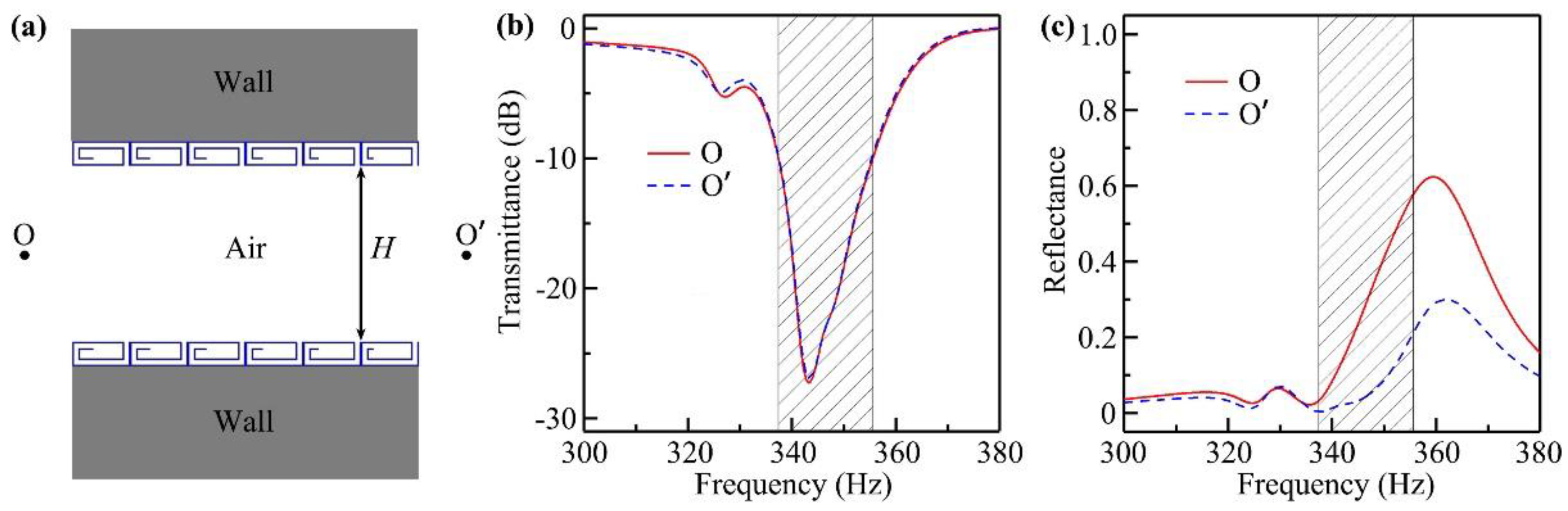
3. Design and Performance of Low-Frequency Low-Reflection BSI Tunnels

Next, we designed a low-frequency low-reflection BSI tunnel, which consisted of a pair of ultrathin AMs attached symmetrically on both sides. The schematic diagram of the proposed tunnel is shown in Figure 3a, in which a cylindrical sound source was separately placed at the point O or O′ in the following studies. The corresponding settings of the numerical models are shown in Table 1. Figure 3b,c show the simulated transmittance and reflectance spectra through the tunnel, respectively. We can see that the transmittance spectra were almost the same for both cases, and the transmittances were below −10 dB in the range 337–356 Hz (black shaded region), with a minimum value of −27 dB at 343 Hz, showing a typical characteristic of low-frequency BSI. Beyond that, the thickness h of the AM was 28.5 mm, which is equal to λ/35 at the valley of spectra, exhibiting an ultrathin characteristic of the AM. However, it is worth noting that the incident sound energy was not reflected totally for both cases (shown in Figure 3c), and the reflectance spectra were different in the working band, in which the reflectances excited by the cylindrical sound source at O′ were obviously lower than those at O, a result that may have arisen from different mechanisms of sound modulations on both sides.

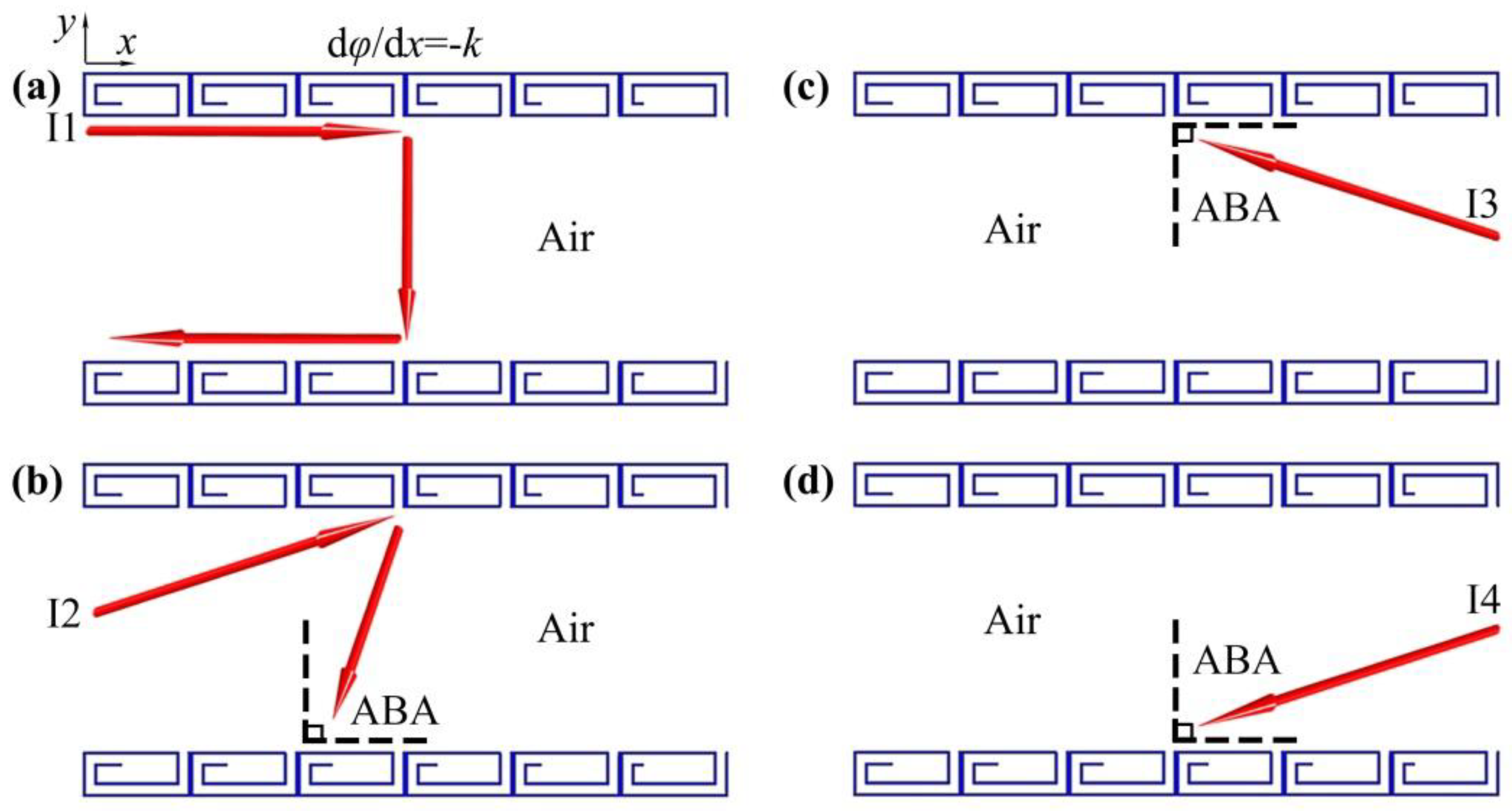
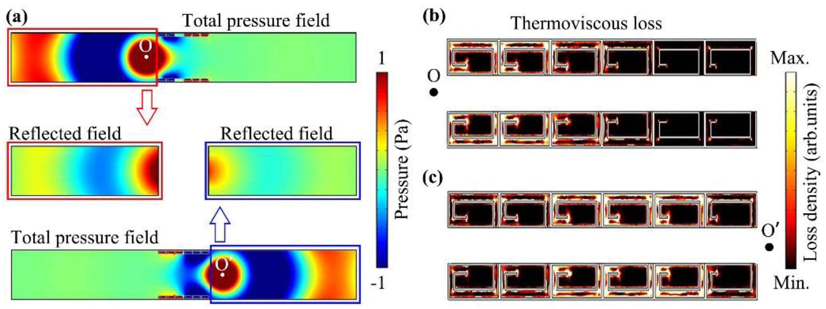
4. Mechanisms of Low-Frequency Low-Reflection BSI

To provide insight into the mechanisms of low-frequency BSI, we present the schematic diagrams of propagation paths in the tunnel for the left and right incidences of sound based on wave modulations of both AMs. As shown in Figure 4a, for the incident wave I1 from the left side with the angle θi = 90°, the sound energy was reflected by the upper AM with θr = 0° and then was reflected back by the bottom AM with θr = −90°. Beyond that, for the other incident waves with the arbitrary angle in the range 0° < θi < 90° (I2 in Figure 4b), the incident wave was reflected by the upper AM with the angle θr < 0°, and therefore, the sound energy was reflected to the bottom AM, which was transformed into the surface evanescent wave owing to the ABA. Figure 4c,d show the propagation paths of the incident waves I3 and I4, respectively, from the right side with the arbitrary angle in the range −90° ≤ θi < 0°. We can see that I3 and I4 could be directly transformed into the surface evanescent wave by the AMs on both sides of the tunnels, owing to the ABA. Therefore, based on the sound reflections and the ABA created by the gradient phase of the AMs, the incident sound energy on both sides could not transmit through the tunnel.
In addition to the low-frequency BSI, we also simulated the low-reflection characteristic of the tunnel. Figure 5a shows the simulated total pressure distributions and the corresponding reflected pressure distributions through the tunnel by separately placing a cylindrical sound source at O and O′ at 343 Hz. We can see that the incident sound energy almost could not transmit through the tunnel in both cases, showing the characteristic of low-frequency BSI. However, as shown in the middle two insets, there still existed a certain amount of reflected sound energy for the sound incidences from both sides. It is obvious that the sound reflection from the sound source at O′ was much weaker than that at O, showing the typical characteristics of low-reflection sound for the left and right incidences, especially for the right incidence, which agrees well with that in Figure 3c.
Next, we also simulated the distributions of thermoviscous loss density in the unit cells of both AMs for the left and right incidences at 343 Hz, which are shown in Figure 5b,c, respectively. For the left incidence (Figure 5b), the thermoviscous energy loss was mainly in the coiled channels of the left three unit cells, owing to the sound reflections and the existence of the ABA (Figure 4a,b). However, for the right incidence (Figure 5c), the thermoviscous energy loss was almost distributed in the coiled channels of all unit cells. This is because the incident sound energy from the right side was transformed into the surface evanescent wave, propagating on the surfaces of both AMs (Figure 4c,d). Thus, the total thermoviscous energy loss in the unit cells of both AMs for the left incidence was obviously weaker than that for the right incidence, which was consistent with the reflected sound energy on both sides of tunnel (Figure 5a). Based on the above theoretical analysis, we can conclude that the low-frequency low-reflection BSI of the tunnel arose from the sound reflections and the ABA created by the AMs and the thermoviscous energy loss in the coiled channels of the unit cells.

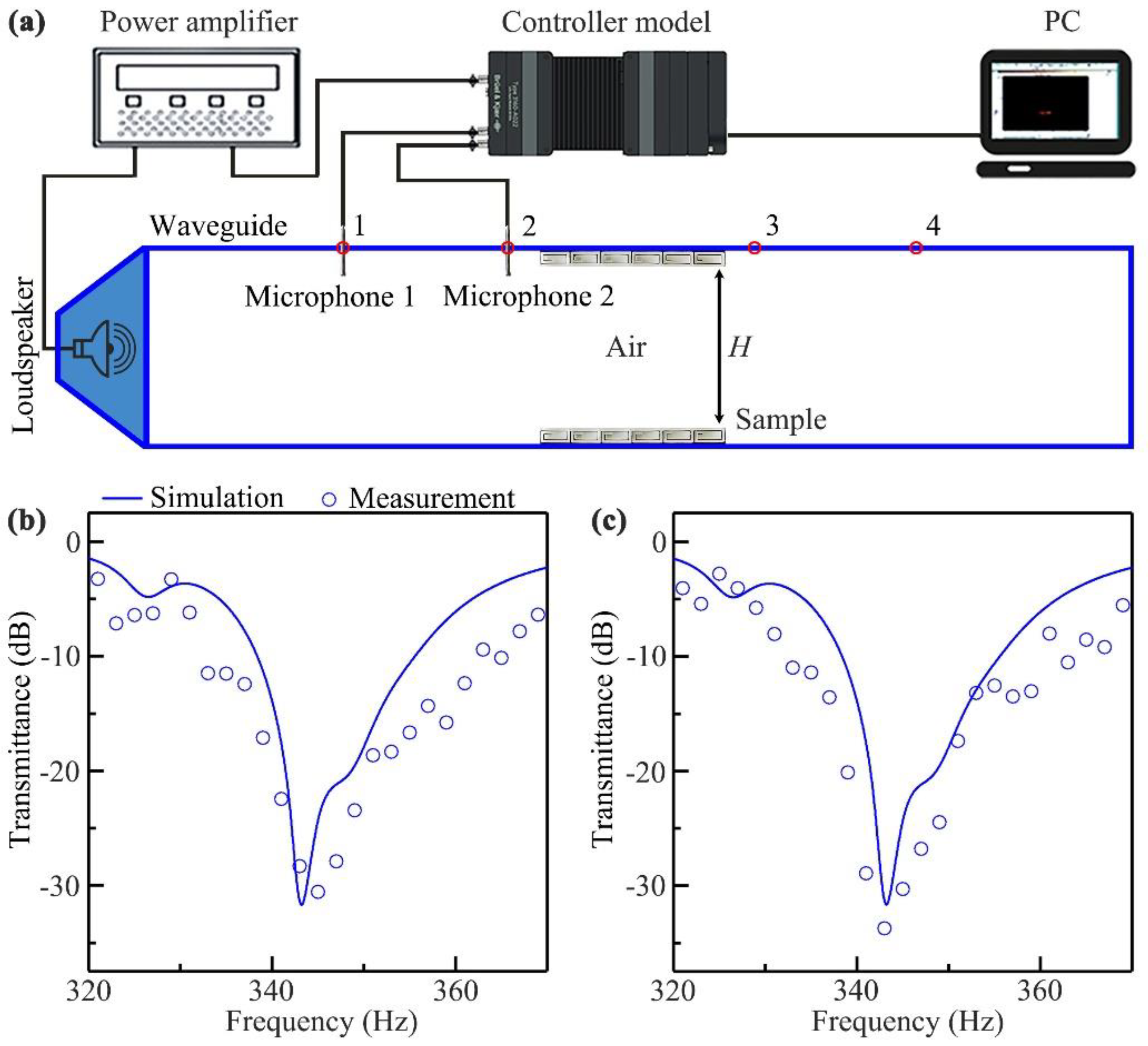
5. Experimental Verification

To experimentally demonstrate the performance of the designed tunnel, we experimentally measured the transmittance spectra through the sample for the left and right incidences in a straight waveguide with the size of 2 × 0.4 × 0.06 m3. The experimental set-up is shown in Figure 6a. The sample, made of epoxy resin by 3D printing technology, was placed in the middle region of the waveguide, which was constructed from acrylic plates to satisfy the sound-hard boundary condition. The parameters of the sample were the same as those in Figure 3a. A loudspeaker, driven by a power amplifier, was placed at the left entrance to generate incident sound signals, and two 0.25 inch microphones marked as Microphones 1 and 2 were separately placed into the waveguide at Holes 1 and 2 and the Holes 3 and 4 to detect sound signals. The measured data was recorded by the controller module, and was analyzed by the software PULSE Labshop. The types of instruments used in the experimental measurement are listed in Table 3.
Figure 6b,c show the measured transmittance spectra (blue open circles) through the sample for the left and right incidences of plane sound waves, respectively, in which the simulated results with the same conditions are also displayed for comparison (blue solid lines). We can see that the performances of low-frequency BSI were almost the same for both cases, and the minimum value of transmittance reached about −31 dB at 343 Hz. The measured spectra agreed well with their corresponding simulations. Therefore, the low-frequency BSI of the tunnel is experimentally demonstrated.

6. Application of Tunnel in Open Window with Low-Frequency Low-Reflection BSI

Finally, to further explore the practical application of the designed tunnel, we also designed an open-window structure with low-frequency low-reflection BSI, which consisted of seven tunnels (shown in Figure 7a). The structure and all parameters of the AMs on both sides of each tunnel were the same as those in Figure 3a. Figure 7b shows the simulated transmittance spectra through the open window, in which a cylindrical sound source was separately placed at the points O and O′, and the corresponding settings of the models are shown in the Table 1. We can see that the performances of low-frequency BSI created by the open window were almost the same for the sound incidence from both sides. The transmittances were lower than −10 dB in the range 341–360 Hz (black shaded region), and the minimum value reached −30 dB at 348 Hz. Figure 7c,d show the simulated total pressure distributions through the open window for both cases at 348 Hz. The simulated results obviously show that, in both cases, the incident cylindrical sound waves could not transmit through the designed open window, but the other media (such as air, heat and light) could achieve free transport on both sides, showing a perfect effect of low-frequency BSI.

7. Conclusions

We demonstrated a type of low-frequency low-reflection BSI tunnel, which was constructed by a pair of ultrathin lossy AMs (about λ/35) with the phase gradient d φ / d x = k attached symmetrically on both sides of a straight tunnel. Based on the generalized Snell′s law and the phase modulations by both AMs, we designed a tunnel with a low-frequency BSI, in which the transmittances were lower than −10 dB in the range 337–356 Hz, and the minimum value reached about −27 dB at 343 Hz. Such a phenomenon can be explained by the sound reflections and the ABA created by the AMs for the left and right incidences of sound. In addition to the characteristics of low-frequency BSI, the low reflection of sound through the tunnel was simultaneously achieved by the thermoviscous energy loss in the coiled channels of the unit cells. The measured results agreed well with the simulated ones. Finally, the potential application of the tunnel in the design of an open-window structure with low-frequency low-reflection BSI was further simulated in detail.
The proposed open tunnel and window structures showed high performance characteristic of low-frequency low-reflection BSI, which has potential applications in designing sound insulation rooms. The ultrathin structure of AMs and the highly efficient ventilation of open structures provide high-performance heat dissipation. Beyond that, it can also be applied to design ventilation ducts and corridors of BSI. Future work may focus on performance modulations of open sound insulation structures.

Author Contributions

Conceptualization, Y.-J.G. and H.-X.S.; methodology, Y.-J.G., Y.-W.X. and Y.G.; validation, Y.-J.G., Y.-W.X. and Y.G.; formal analysis, Y.-J.G. and H.-X.S.; writing—original draft preparation, Y.-J.G.; writing—review and editing, H.-X.S.; supervision, H.-X.S., S.-Q.Y. and X.-J.L. All authors have read and agreed to the published version of the manuscript.

Funding

This work was supported by the National Key Research and Development Program of China (Grant No. 2020YFC1512403), the National Natural Science Foundation of China (Grant Nos.12174159 and 11834008) and the Practice Innovation Training Program Projects of Jiangsu Province (Grant No. 202110299082Z).

Institutional Review Board Statement

Not applicable.

Informed Consent Statement

Not applicable.

Data Availability Statement

The data are contained within the article. Further inquiries can be directed to the corresponding authors.

Conflicts of Interest

The authors declare no conflict of interest.

References

  1. Zarek, J.H.B. Sound absorption in flexible porous materials. J. Sound Vib. 1978, 61, 205–234. [Google Scholar] [CrossRef]
  2. Arenas, J.P.; Crocker, M.J. Recent trends in porous sound-absorbing materials. Sound Vib. 2010, 44, 12–17. [Google Scholar]
  3. Toyoda, M.; Sakagami, K.; Takahashi, D.; Morimoto, M. Effect of a honeycomb on the sound absorption characteristics of panel-type absorbers. Appl. Acoust. 2011, 72, 943–948. [Google Scholar] [CrossRef] [Green Version]
  4. Liu, Z.Y.; Zhang, X.X.; Mao, Y.W.; Zhu, Y.Y.; Yang, Z.Y.; Chan, C.T.; Sheng, P. Locally resonant sonic materials. Science 2000, 289, 1734–1736. [Google Scholar] [CrossRef]
  5. Fang, N.; Xi, D.J.; Xu, J.Y.; Ambati, M.; Srituravanich, W.; Sun, C.; Zhang, X. Ultrasonic metamaterials with negative modulus. Nat. Mater. 2006, 5, 452–456. [Google Scholar] [CrossRef]
  6. Li, J.; Fok, L.; Yin, X.B.; Bartal, G.; Zhang, X. Experimental demonstration of an acoustic magnifying hyperlens. Nat. Mater. 2009, 8, 931–934. [Google Scholar] [CrossRef]
  7. Christensen, J.; de Abajo, F.J.G. Anisotropic metamaterials for full control of acoustic waves. Phys. Rev. Lett. 2012, 108, 124301. [Google Scholar] [CrossRef]
  8. Liang, Z.X.; Li, J.S. Extreme acoustic metamaterial by coiling up space. Phys. Rev. Lett. 2012, 108, 114301. [Google Scholar] [CrossRef]
  9. Cummer, S.A.; Christensen, J.; Alu, A. Controlling sound with acoustic metamaterials. Nat. Rev. Mater. 2016, 1, 16001. [Google Scholar] [CrossRef] [Green Version]
  10. Tsang, L.; Liao, T.H.; Tan, S.R. Calculations of Bands and Band Field Solutions in Topological Acoustics Using the Broadband Green’s Function-KKR-Multiple Scattering Method. Prog. Electromagn. Res. 2021, 171, 137–158. [Google Scholar] [CrossRef]
  11. Jia, D.; Wang, Y.; Ge, Y.; Yuan, S.Q.; Sun, H.X. Tunable topological refractions in valley sonic crystals with triple valley hall phase transitions. Prog. Electromagn. Res. 2021, 172, 13–22. [Google Scholar] [CrossRef]
  12. Shen, L.; Zhu, Y.F.; Mao, F.L.; Gao, S.Y.; Su, Z.H.; Luo, Z.T.; Zhang, H.; Assouar, B. Broadband low-frequency acoustic metamuffler. Phys. Rev. Appl. 2021, 16, 064057. [Google Scholar] [CrossRef]
  13. Ciaburro, G.; Iannace, G. Modeling acoustic metamaterials based on reused buttons using data fitting with neural network. J. Acoust. Soc. Am. 2021, 150, 51–63. [Google Scholar] [CrossRef] [PubMed]
  14. Li, Y.; Liang, B.; Gu, Z.M.; Zou, X.Y.; Cheng, J.C. Reflected wavefront manipulation based on ultrathin planar acoustic metasurfaces. Sci. Rep. 2013, 3, 2546. [Google Scholar] [CrossRef] [Green Version]
  15. Mei, J.; Wu, Y. Controllable transmission and total reflection through an impedance-matched acoustic metasurface. New J. Phys. 2014, 16, 123007. [Google Scholar] [CrossRef]
  16. Tang, K.; Qiu, C.Y.; Ke, M.Z.; Lu, J.Y.; Ye, Y.T.; Liu, Z.Y. Anomalous refraction of airborne sound through ultrathin metasurfaces. Sci. Rep. 2014, 4, 6517. [Google Scholar] [CrossRef] [Green Version]
  17. Xie, Y.B.; Wang, W.Q.; Chen, H.Y.; Konneker, A.; Popa, B.I.; Cummer, S.A. Wavefront modulation and subwavelength diffractive acoustics with an acoustic metasurface. Nat. Commun. 2014, 5, 5553. [Google Scholar] [CrossRef]
  18. Tian, Y.; Wei, Q.; Cheng, Y.; Xu, Z.; Liu, X.J. Broadband manipulation of acoustic wavefronts by pentamode metasurface. Appl. Phys. Lett. 2015, 107, 221906. [Google Scholar] [CrossRef]
  19. Xie, B.Y.; Tang, K.; Cheng, H.; Liu, Z.Y.; Chen, S.Q.; Tian, J.G. Coding acoustic metasurfaces. Adv. Mater. 2017, 29, 1603507. [Google Scholar] [CrossRef]
  20. Hu, Z.P.; He, N.; Sun, Y.W.; Jin, Y.; He, S.L. Wideband high-reflection chiral dielectric metasurface. Prog. Electromagn. Res. 2021, 172, 51–60. [Google Scholar] [CrossRef]
  21. Li, Z.P.; Cao, G.T.; Li, C.H.; Dong, S.H.; Deng, Y.; Liu, X.K.; Ho, J.S.; Qiu, C.W. Non-Hermitian Electromagnetic Metasurfaces at Exceptional Points. Prog. Electromagn. Res. 2021, 171, 1–20. [Google Scholar] [CrossRef]
  22. Ciaburro, G.; Iannace, G. Membrane-type acoustic metamaterial using cork sheets and attached masses based on reused materials. Appl. Acoust. 2022, 189, 108605. [Google Scholar] [CrossRef]
  23. Jimenez, N.; Huang, W.; Romero-Garcia, V.; Pagneux, V.; Groby, J.-P. Ultra-thin metamaterial for perfect and quasi-omnidirectional sound absorption. Appl. Phys. Lett. 2016, 109, 121902. [Google Scholar] [CrossRef]
  24. Li, J.F.; Wang, W.Q.; Xie, Y.B.; Popa, B.-I.; Cummer, S.A. A sound absorbing metasurface with coupled resonators. Appl. Phys. Lett. 2016, 109, 091908. [Google Scholar] [CrossRef]
  25. Long, H.Y.; Cheng, Y.; Liu, X.J. Asymmetric absorber with multiband and broadband for low-frequency sound. Appl. Phys. Lett. 2017, 111, 143502. [Google Scholar] [CrossRef]
  26. Huang, S.B.; Zhou, Z.L.; Li, D.T.; Liu, T.; Wang, X.; Zhu, J.; Li, Y. Compact broadband acoustic sink with coherently coupled weak resonances. Sci. Bull. 2020, 65, 373. [Google Scholar] [CrossRef] [Green Version]
  27. Mei, J.; Ma, G.C.; Yang, M.; Yang, Z.Y.; Wen, W.J.; Sheng, P. Dark acoustic metamaterials as super absorbers for low-frequency sound. Nat. Commun. 2012, 3, 756. [Google Scholar] [CrossRef] [Green Version]
  28. Wei, P.; Croenne, C.; Chu, S.T.; Li, J. Symmetrical and anti-symmetrical coherent perfect absorption for acoustic waves. Appl. Phys. Lett. 2014, 104, 121902. [Google Scholar] [CrossRef]
  29. Song, J.Z.; Bai, P.; Hang, Z.H.; Lai, Y. Acoustic coherent perfect absorbers. New J. Phys. 2014, 16, 033026. [Google Scholar] [CrossRef] [Green Version]
  30. Cai, X.B.; Guo, Q.Q.; Hu, G.K.; Yang, J. Ultrathin low-frequency sound absorbing panels based on coplanar spiral tubes or coplanar Helmholtz resonators. Appl. Phys. Lett. 2014, 105, 121901. [Google Scholar] [CrossRef] [Green Version]
  31. Tang, Y.F.; Xin, F.X.; Huang, L.X.; Lu, T.J. Deep subwavelength acoustic metamaterial for low-frequency sound absorption. Eur. Phys. Lett. 2017, 118, 44002. [Google Scholar] [CrossRef]
  32. Wang, X.L.; Luo, X.D.; Zhao, H.; Huang, Z.Y. Acoustic perfect absorption and broadband insulation achieved by double-zero metamaterials. Appl. Phys. Lett. 2018, 112, 021901. [Google Scholar] [CrossRef]
  33. Donda, K.; Zhu, Y.F.; Fan, S.W.; Cao, L.Y.; Li, Y.; Assouar, B. Extreme low-frequency ultrathin acoustic absorbing metasurface. Appl. Phys. Lett. 2019, 115, 173506. [Google Scholar] [CrossRef]
  34. Guan, Y.J.; Ge, Y.; Sun, H.X.; Yuan, S.Q.; Lai, Y.; Liu, X.J. Ultra-thin metasurface-based absorber of low-frequency sound with bandwidth optimization. Front. Mater. 2021, 8, 764338. [Google Scholar] [CrossRef]
  35. Zhang, C.; Hu, X.H. Three-dimensional single-port labyrinthine acoustic metamaterial: Perfect absorption with large bandwidth and tunability. Phys. Rev. Appl. 2016, 6, 064025. [Google Scholar] [CrossRef] [Green Version]
  36. Yang, M.; Chen, S.Y.; Fuab, C.X.; Sheng, P. Optimal sound-absorbing structures. Mater. Horiz. 2017, 4, 673–680. [Google Scholar] [CrossRef] [Green Version]
  37. Wu, X.X.; Fu, C.X.; Li, X.; Meng, Y.; Gao, Y.B.; Tian, J.X.; Wang, L.; Huang, Y.Z.; Yang, Z.Y.; Wen, W.J. Low-frequency tunable acoustic absorber based on split tube resonators. Appl. Phys. Lett. 2016, 109, 043501. [Google Scholar] [CrossRef]
  38. Guan, Y.J.; Ge, Y.; Sun, H.X.; Yuan, S.Q.; Liu, X.J. Low-frequency, open, sound-insulation barrier by two oppositely oriented Helmholtz resonators. Micromachines 2021, 12, 1544. [Google Scholar] [CrossRef]
  39. Zhang, H.L.; Zhu, Y.F.; Liang, B.; Yang, J.; Yang, J.; Cheng, J.C. Omnidirectional ventilated acoustic barrier. Appl. Phys. Lett. 2017, 111, 203502. [Google Scholar] [CrossRef] [Green Version]
  40. Cheng, Y.; Zhou, C.; Yuan, B.G.; Wu, D.J.; Wei, Q.; Liu, X.J. Ultra-sparse metasurface for high reflection of low-frequency sound based on artificial Mie resonances. Nat. Mater. 2015, 14, 1013–1019. [Google Scholar] [CrossRef]
  41. Gao, Y.X.; Cheng, Y.; Liang, B.; Li, Y.; Yang, J.; Cheng, J.C. Acoustic skin meta-muffler. Sci. China-Phys. Mech. Astron. 2021, 64, 294311. [Google Scholar] [CrossRef]
  42. Ghaffarivardavagh, R.; Nikolajczyk, J.; Anderson, S.; Zhang, X. Ultra-open acoustic metamaterial silencer based on Fano-like interference. Phys. Rev. B 2019, 99, 024302. [Google Scholar] [CrossRef]
  43. Ge, Y.; Sun, H.X.; Yuan, S.Q.; Xia, J.P. Asymmetric acoustic transmission in an open channel based on multiple scattering mechanism. Appl. Phys. A 2017, 123, 328. [Google Scholar] [CrossRef]
  44. Yu, N.F.; Genevet, P.; Kats, M.A.; Aieta, F.; Tetienne, J.P.; Capasso, F.; Gaburro, Z. Light Propagation with Phase Discontinuities: Generalized Laws of Reflection and Refraction. Science 2011, 334, 333–337. [Google Scholar] [CrossRef] [Green Version]
  45. Shen, C.; Xie, Y.B.; Li, J.F.; Cummer, S.A.; Jing, Y. Acoustic metacages for sound shielding with steady air flow. J. Appl. Phys. 2018, 123, 124501. [Google Scholar] [CrossRef]
  46. Zhang, H.L.; Zhu, Y.F.; Liang, B.; Yang, J.; Yang, J.; Cheng, J.C. Sound insulation in a hollow pipe with subwavelength thickness. Sci. Rep. 2017, 7, 44106. [Google Scholar] [CrossRef] [Green Version]
  47. Ge, Y.; Sun, H.X.; Yuan, S.Q.; Lai, Y. Broadband unidirectional and omnidirectional bidirectional acoustic insulation through an open window structure with a metasurface of ultrathin hooklike meta-atoms. Appl. Phys. Lett. 2018, 112, 243502. [Google Scholar] [CrossRef]
  48. Ge, Y.; Sun, H.X.; Yuan, S.Q.; Lai, Y. Switchable omnidirectional acoustic insulation through open window structures with ultrathin metasurfaces. Phys. Rev. Mater. 2019, 3, 065203. [Google Scholar] [CrossRef]
Figure 1. (a) Schematic of a low-frequency ultrathin unit cell with a coiling space structure. (b) Phase delays of a normally incident wave created by the unit cell as a function of parameter d at 370 Hz. Six red open circles represent the selected units, with d = 6.0 mm, 9.4 mm, 11.7 mm, 13.4 mm, 14.8 mm and 16.1 mm from left to right.
Applsci 12 03470 g001
Figure 2. (a) Schematic of designed AM composed of 6 unit cells. (b) Theoretical continuous (blue solid line) and discrete (red open circles) phase delays of the AM. Schematic of theoretical propagation paths of the reflected waves (blue solid arrows) created by the AM for the incident waves (red solid arrows) with the angles (c) θi = 90°, (d) 30° < θi < 90°, (e) θi = 30°, (f) 0° < θi < 30°, (g) θi = 0° and (h) −90° ≤ θi < 0°.
Applsci 12 03470 g002
Figure 3. (a) Schematic of a tunnel structure with low-frequency low-reflection BSI. A cylindrical sound source is separately placed at the point O or O′. The tunnel width H is 343 mm. The distance between the sound source and adjacent tunnel entrance is 100 mm. We simulated (b) transmittance and (c) reflectance spectra through the tunnel by separately placing a cylindrical sound source at the points O and O′. Black shaded regions show the sound transmittances below −10 dB.
Applsci 12 03470 g003
Figure 4. Schematic of acoustic propagation paths through the tunnel for the incident waves (a) I1, (b) I2, (c) I3 and (d) I4.
Applsci 12 03470 g004
Figure 5. (a) We simulated total pressure distributions and corresponding reflected pressure distributions through the low-frequency BSI tunnel by separately placing a cylindrical sound source at O and O′ at 343 Hz. We also simulated thermoviscous loss density distributions in the unit cells by separately placing a cylindrical sound source at the points (b) O and (c) O′ at 343 Hz.
Applsci 12 03470 g005
Figure 6. (a) Experimental set-up. Sample photograph was placed in the middle region of the waveguide. We measured and simulated transmittance spectra through the sample in a waveguide for the (b) left and (c) right incidences of plane sound waves.
Applsci 12 03470 g006
Figure 7. (a) Schematic of an open-window structure with low-frequency low-reflection BSI, in which a cylindrical sound source was separately placed at the point O or O′. (b) We simulated transmittance spectra through the open window by separately placing a cylindrical sound source at the point O and O′. We also simulated pressure distributions through the open window by separately placing a cylindrical sound source at the points (c) O and (d) O′ at 348 Hz.
Applsci 12 03470 g007
Table 1. Settings of numerical models.
Numerical ModelSetting
Region out of the unit cellModule of Acoustic Pressure
Region in the unit cellModule of Thermoviscous Acoustic-Solid Interaction
Surfaces of the unit cellThermoviscous acoustic boundary layers
Interfaces between regions in and out of unit cellsAcoustic-thermoviscous acoustic coupling boundary
Table 2. Material parameters of numerical models.
ParameterEpoxy ResinAir
Density (ρ)1180 kg/m3 p 0 M / R T
Longitudinal wave velocity (cl)2720 m/s γ R T / M
Transversal wave velocity (ct)1460 m/s/
Molar mass (M)/28.97 × 10−3 kg/mol
Ratio of the molar heat capacities (γ)/1.4
Molar gas constant (R)/8.31 J/(mol/K)
Air pressure (p0)/101.325 kPa
Air temperature (T)/293 K
Coefficient of dynamic viscosity (μ)/1.56 × 10−5 Pa·s
Table 3. Types of instruments.
InstrumentType
Power amplifierPA-50
Controller modelBrüel & Kjær 3160-A-022
MicrophoneBrüel & Kjær type-4954
Publisher’s Note: MDPI stays neutral with regard to jurisdictional claims in published maps and institutional affiliations.

