Article

Bentonite–Concrete Interactions in Engineered Barrier Systems during the Isolation of Radioactive Waste Based on the Results of Short-Term Laboratory Experiments

1
Institute of Geology of Ore Deposits, Petrography, Mineralogy and Geochemistry, Russian Academy of Science (IGEM RAS), Staromonetny Per. 35, 119017 Moscow, Russia
2
Geological Faculty, M. Lomonosov Moscow State University, Leninskie Gory 1, 119991 Moscow, Russia
3
Department of High Energy Chemistry and Radioecology, D. Mendeleyev University of Chemical Technology of Russia, Miusskaya Sq. 9, 125047 Moscow, Russia
4
Department of Mineralogy and Gemology, Geological Prospecting Faculty, Sergo Orzhonikidze Russian State University for Geological Prospecting, Miklouho-Maclay St. 23, 117997 Moscow, Russia
5
Nuclear Safety Institute, Russian Academy of Science (IBRAE RAS), 2nd Tulsky Lane, 2/52, 115191 Moscow, Russia
6
Institute of Precambrian Geology and Geochronology, Russian Academy of Sciences, 199034 St. Petersburg, Russia
7
Department of Closed Nuclear Fuel Cycle Technology, Nuclear University «MEPhI», Kashirskoe Highway 31, 115409 Moscow, Russia
*
Author to whom correspondence should be addressed.
Appl. Sci. 2022, 12(6), 3074; https://doi.org/10.3390/app12063074
Submission received: 25 December 2021 / Revised: 3 March 2022 / Accepted: 9 March 2022 / Published: 17 March 2022
(This article belongs to the Special Issue Applied Geochemistry and Clay Science)

Abstract

:
Bentonite clays have unique properties that determine their use as the main component of engineered barrier systems (EBS) for the isolation of radioactive waste. At present, the Russian Federation is elaborating the concept of deep geological disposal of radioactive waste in crystalline rocks of the Yeniseisky site, where bentonite clays play an important role in ensuring the safety of the repository for a long period of time. This work demonstrates the first results of short-term laboratory experiments (1 and 3 months) on the thermochemical interaction of bentonite and concrete in the presence of synthetic water at an elevated temperature. These experiments will help predict the effect of EBS materials on montmorillonite. Bentonite from the 10th Khutor deposit (Russia) and Portland cement were used in the experiments. At the first stage of the experiments, solutions were obtained after leaching the concrete with a synthetic groundwater solution for 1 month at 90 °C. At the second stage, the interactions of the obtained solutions with bentonite at 90 °C were studied. As a result of the experiments, the processes of concrete leaching were revealed, which changed the composition and acidity (an increase in the pH from 6.1 to 12.1) of the synthetic water and led to an increase in the porosity of the material in contact with the solution. However, no dissolution of montmorillonite was observed, and the changes were quite small. The research results show the high stability of bentonite from the 10th Khutor deposit under model conditions, which was confirmed by modeling. Thus, we can say that at pH ≈ 12 and at elevated temperatures, montmorillonite retains a stable structure for a long time, which is important for ensuring the safety of disposal in general.

1. Introduction

The disposal of radioactive waste (RW) represents an intricate technological problem. Presently, deep geological repositories (DGRs) are unanimously recognized by the international community [1] as the safest option for the isolation of high-level radioactive waste (HLW) from the biosphere. Waste disposal in geological formations must reliably isolate RW from the biosphere over very long periods of time and guarantee that the concentrations of residual radioactive substances reaching the biosphere are insignificant in comparison to the natural background levels of radioactivity. In addition, DGRs must provide sufficient confidence in the minimal risk of occasional human interference.
Most concepts of RW isolation from the biosphere are based on passive multibarrier systems. Such systems usually include a natural geological barrier created by rock formation, wherein the repository/disposal is built, along with a complex of artificial (engineered) barrier safety systems (EBSs). Such a principle of multibarrier protection ensures complete system reliability wherein safety is upgraded using materials with different properties, for example, corrosion-resistant materials for RW isolation and/or materials with low permeability for limiting the ingress of groundwater. Within the application of an artificial multibarrier system, at the present time, bentonite or a mixture of bentonite and sand is used in the vast majority of developing concepts as a buffer material, arranged between waste containers and host rock or used for sealing the premises of an underground repository [2,3,4,5]. In such cases, the buffer material may be produced for use in different areas in the form of compacted pellets, such as in a Swiss project [6], or in the form of compacted (pressed) bentonite [2,7].
The key requirements for buffer materials used in the disposal of HLW include low water permeability, the ability to self-heal, and the ability to maintain their properties for long time periods [2,7,8,9,10]. Bentonite and bentonite-like clays possess the complete set of required properties as natural and clayey materials that are capable of swelling. Precisely because of these properties, bentonite has been chosen as a barrier material in national programs in Sweden and Finland considering the option of HLW disposal in fractured rock sites (granite massif) [11,12,13].
Generally, the basic protective functions of an RW repository are retention and deceleration. Retention is defined as complete waste isolation. Meanwhile, the function of deceleration serves to decrease the rate of leak propagation in the event of the loss of tightness. The protective functions of a barrier include how it contributes to the retention and deceleration of radionuclide migration and may be defined on the assumption of understanding the component properties and long-term alternation of EBS. For this, it is necessary to carry out not only laboratory but also full-scale experiments under close-to-real conditions—those that exist in repositories/disposal sites, that is, in an underground research laboratory (URL). Currently, under the auspices of the State Atomic Energy Corporation ROSATOM in Russia, work is underway to create a URL in crystalline rocks at the Yeniseisky site (Krasnoyarsk Territory). This work includes the implementation of experiments to assess the safety of creating DGRs [14].
The properties of the bentonite barrier in general are determined mainly by the characteristics of the structure of the rock-forming mineral from the smectite group—montmorillonite. At the same time, the changes in the properties of bentonite under DGR conditions are largely determined by the transformation of montmorillonite at an elevated temperature in the presence of pore water of the crystalline massif, as well as by its interaction with other EBS components (concrete, metal containers, and glass-like matrices of radioactive waste). Such interactions at the boundary of several phases affecting the properties of the main EBS component (bentonite) are called boundary transformations.
In other countries, the experience in the design and operation of DGRs of radioactive waste includes a wide range of concrete applications that have been proposed for constructing engineering safety barriers to prevent the migration of radionuclides into the environment, such as a concrete lining of storage tunnels; a concrete buffer (backfill) located both inside and outside of the containers of radioactive waste; concrete plugs and seals in tunnels [3,15,16,17]. To create a concrete buffer, cement can be used both individually and in a mixture with bentonite clay and hydrotalcite (a low-alkaline cement composition used in the Cigeo DGR project, France) [18], and slaked lime and ground limestone (cement composition NRVB, UK) [19]. In the scenarios described above, the use of concrete is mainly due to its easy availability, the low cost of raw materials for its manufacture, high strength, low water permeability, resistance to radiation, and the ability to screen ionizing radiation [2,20].
In the DGR project at the Yeniseisky site, at the moment, various options of engineered barriers are being considered in which bentonite can be in contact with concrete. First of all, this involves concreting the walls and waterproofing water-conducting cracks in the tunnels, where it is planned to place materials based on bentonite as a buffer and backfill in the immediate vicinity while considering the setup of a multi-container with a concrete and bentonite buffer, and so forth. [21]. The interaction of concrete and bentonite engineering barrier systems in the conditions of a DGR will lead to phase changes at the site of their contact, as well as the mutual redistribution of ions (Na+, K+, Ca2+, Mg2+, SO42−, Cl) under the influence of groundwater [16,17].
The study by [22] dealt with changes in concrete engineering barriers under the continuous influence of the maximum design temperature loads typical for DGR, 300 °C. Under these conditions, the ultimate compressive strength of concrete decreases by about 25%, and its value will continue to decrease further at temperatures exceeding the maximum limit of 300 °C. When the cement slurry solidifies, this tendency is more pronounced. The hydraulic permeability of concrete also increases under the influence of elevated temperatures, which leads to an increase in porosity. This can lead to an increase in the rate of flow of groundwater through the barriers of the DGR, despite the fact that the effect of change in concrete would be relatively small and comparable to their cracking [22].
When groundwater enters a DGR with a cement backfill, its active components, such as calcium hydroxide, dissolve, and a C-S-H gel is formed due to the hydration of the OPC [21]. As a result, there is a slight increase in the hydraulic permeability of concrete (from 10−11 to 10−10 m/s) due to an increase in porosity [23], which, in turn, leads to a decrease in the mechanical strength of the concrete [24].
The diffusion of sulfate anions from bentonite into concrete and Ca2+ cations from concrete into bentonite leads to the precipitation of calcite and gypsum on the surface of their contact [16,17]. The increased gypsum content in this area promotes the formation of ettringite crystals in the pores of the concrete. Calcite precipitates as a result of the interaction of the carbonate anion of granite groundwater with the calcium hydroxide dissolved from concrete. The saturation of Ca–bentonite with groundwater leads to the diffusion of Ca2+ and Mg2+ ions towards the surface of contact with concrete.
Dissolved by groundwater, chloride and sulfate anions from bentonite diffuse into concrete [16,17]. At the same time, sulfate anions are found within a centimeter from the contact surface of bentonite and concrete, while chloride anions penetrate much deeper into concrete (~5 cm).
Under the influence of waters filtered through OPC, the physical, mechanical and chemical properties change, including a decrease in the pH from 12.5–13.5 to 10–10.5, the dissolution of phases containing Na and K, and the dissolution of portlandite [25,26].
Previous studies have shown that bentonites are stable even in highly acidic environments when heated [27,28,29,30]; however, concrete creates a highly alkaline environment (pH ≈ 12) under the influence of storage facility groundwater, which can cause a change in its physical and chemical properties [31], and, accordingly, a transformation of the structure of the montmorillonite [32] found in immediate contact with concrete.
As the main component of bentonite, smectite is exposed to the negative effects of highly alkaline solutions. Globally, studies of the stability of bentonites, and, in particular, smectites, in alkaline solutions have been carried out for more than 10 years. In the works of a large number of authors [33,34,35,36,37,38,39,40,41,42,43,44,45,46,47] and others, one can single out the main conclusion that pH has a key effect on the stability of smectite. As a result of various laboratory experiments, it has been shown that the reactivity of smectite increases significantly with increasing pH starting at 12 [33,36,41,46]. Moreover, the use of simulations by Savage et al. [45,48,49] revealed that smectite dissolution processes are already significant at a pH of 12.5.
In a study by Fernández et al. [47], bentonites were subjected to the thermochemical action of a highly alkaline K-Na-OH-type raster, simulating the early stage of OPC leaching. The experiments were carried out at a temperature of 150 °C. Four bentonites were tested in the experiments; three of them were montmorillonite bentonites and one was saponite. The results of the study showed that trioctahedral smectite showed greater resistance to dissolution than dioctahedral ones. There was also precipitation of secondary phases, such as zeolites and K-feldspar. Of the dioctahedral smectites, smectite with the highest charge of the tetrahedral network and the most heterogeneous composition showed the greatest stability.
In studies [33,39,42,50] on the reaction of bentonite with alkaline solutions, it has been noted that in solutions with a high content of K+, the partial illitization of smectite can occur with the formation of mixed-layer minerals, which was also noted in the study by Dauzeres et al. [51] in the paper presented by the authors’ summary table. In bentonites, the dissolution of smectite is accelerated, but so too is the dissolution of quartz and amorphous silica [37,52]. In Karnland et al. [37], the dissolution of smectite occurred through the beidellization step, but K was not used in their experimental solutions. In experiments [52] carried out over 6 years with 5 M NaOH and 5 M KOH solutions, smectite dissolution was observed in parallel with the transformation of dioctahedral smectite into trioctahedral due to an increase in the proportion of magnesium in the octahedral networks. The formation of various zeolites was also observed. In studies [17,53], an increase in the proportion of trioctahedral smectite has also been observed by the same mechanism.
The processes of the interaction of concrete with groundwater, as well as the interaction in the concrete–bentonite system, need to be studied in detail, since this, in general, can lead to a decrease in the operational characteristics of the EBS.
The purpose of this study was to identify the patterns of structural transformations of montmorillonite as the main component of the bentonite buffer in contact with cement/the concrete materials of EBS, which can be used in DGRs both as insulating materials and as matrices for IL/LL RW.
The processes that occur under the conditions of the underground disposal facility are due to a complex of various chemical and physical processes associated with the geological conditions of the underground disposal facility, as well as with the EBS materials used for the isolation of radioactive waste [32].
The experiments described in this work were aimed at investigating the stability of concrete and bentonite as EBS materials under conditions of elevated temperatures, simulating heating from radioactive waste.
The creation of geochemical models is necessary for the purposes of the adequate prediction of the evolution of models for the evolution of barrier materials. These models should be built on the basis of an experimental study since the uncritical use of model parametrization based on literature values can lead to incorrect predictions.
As emphasized in the review paper [54], which was devoted to the creation of a database on the processes of sedimentation and the dissolution of solid phases of clay minerals, the measured rates of laboratory experiments and the rates measured directly under the conditions of a DGR may differ by several orders of magnitude; significant differences can also be observed in similar experiments with the same material. However, these models can open our eyes to the evolution of barriers since the duration of the experiments is not comparable with the time spent by the materials under study in the conditions of the DGR. The creation of geochemical models is necessary for the purpose of the adequate prediction of the evolution of models of the evolution of barrier materials (thus, using the modeling of Savage et al., [45,48,49] have revealed that the processes of dissolution of smectite are significant even at a pH of 12.5).
These models of the evolution of the properties of bentonite materials should be built on the basis of data obtained in the course of an experimental study since the uncritical use of model parametrization based on literature values can lead to incorrect predictions.
The results obtained can be used to substantiate the choice of bentonite for the creation of an EBS, as well as to assess the safety of a DGR in the short and long term.

2. Materials and Methods

As materials for engineering the barriers for the experiments to simulate the conditions in the DGR, we used concrete based on Portland cement and bentonite from the 10th Khutor deposit. At the moment, the question of the composition of cements for concreting the walls of the mining tunnels in geological disposal sites, which are being developed in crystalline rocks of the Yeniseisky subsoil area, has not been resolved. We took Portland cements as the least stable in the conditions of underground waste disposal; thus, in the course of the experiments, the worst-case scenarios of the evolution of the DGR were modeled.
Bentonites from the 10th Khutor deposit, which is one of the deposits of the bentonite province of the Minusinsk depression in the Republic of Khakassia, were selected as clay raw materials [55,56]. The sample for the study was provided by representatives of Company Bentonit LLC together with Bentonite Khakassia LLC. According to the granulometric composition, the sample is, according to the classification of V.V. Okhotina, silty clay of the following composition: 0% -> 0.1 mm, 39% −0.1–0.05 mm, 5% −0.05–0.01 mm, 10% −0.01–0.002 mm, 46%–<0.002 mm.

2.1. Bentonites of the 10th Khutor Deposit

The 10th Khutor deposit is located in the Republic of Khakassia and is part of a group of deposits of volcanogenic-sedimentary genesis (together with the Beintoyskoye and Karasukskoye deposits, Figure 1), with total reserves of more than 13 million tons [57].
All these deposits are confined to the exploitation of the Sarskaya suite, which is a part of the continental tuff–sandy–argillaceous coal formation of the Carboniferous age, filling the Chernogorsk basin of the South Minusinsk depression. The Chernogorsk basin is a flat-bottomed syncline covering an area of about 850 km2 [57]. The coal formation filling the basin is bentonite-bearing. The formation is composed of tuffs, tuffites, conglomerates, sandstones, siltstones, argillites, limestones, and carbonaceous rocks with seams and interlayers of coal and bentonites. The bedding of the rocks within the deposit is monoclonal with a northeastern strike, dipping to the southeast at an angle of 6–8 degrees. The strata were traced along the dip at 100–125 m with a depth of 25 m. No tectonic faults were found within the field. The lithological composition of the bentonite deposits includes five members—underlying, low productive, interproductive, upper productive, and overlying [55,57].

2.2. Concrete

The concrete for the experiment was prepared from a mixture of CEM III/A 42.5 H. The ratio of water to cement was 3:5. The resulting mixture was poured into molds, after which the molds with not-yet-hardened concrete were placed in a desiccator with distilled water for three days. Then, the resulting concrete cylinders were left to harden for another 27 days. The total curing time was 30 days. The concrete samples were made in the form of cylinders 10 mm high and 12 mm in diameter.

2.3. Composition of the Synthetic Water

Experiments on the leaching of concrete were carried out in a solution simulating the pore water of the crystalline massif of the Yeniseisky site, Krasnoyarsk Region. The composition of the model water for the experiments was taken from the data [58,59], with some adjustments that brought the composition of the synthetic water closer to the real pore water. The actual chemical composition of the solution is shown in Table 1.

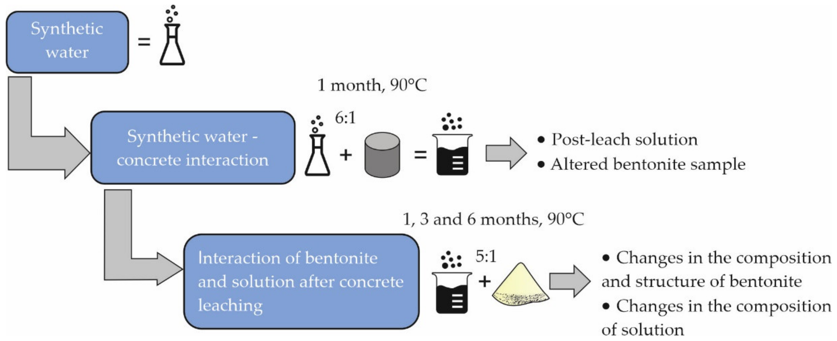
2.4. Experiment Progress

Experimental studies were carried out in order to study the contact interactions and were designed to simulate the conditions that can be achieved in the deep disposal repository of nuclear fuel waste in the case of a realistic scenario of the evolution of the facility after being closed.
All experiments were carried out at a temperature of 90 °C, in 250 mL fluoroplastic beakers with a lid. The concrete leaching experiments were carried out for 40 days, followed by the separation of the solid and liquid phases. The ratio of the solid to liquid phase in the experiments with concrete was 1:6, whereas, for the experiments with bentonite, it was 1:5.
The experiments were carried out in two stages (Figure 1), as follows:
(1)
The leaching of concrete in synthetic water, simulating the Yeniseisky site [58,59].
(2)
The interaction of the solution after the leaching of concrete with bentonite from the 10th Khutor deposit.

2.5. Methods

All samples passed through a system of complex research; the composition of the liquid and solid components, and the structure of the solid component were studied.
The change in the cationic composition of the solution was measured using optical emission spectroscopy on an Agilent 5110 inductively coupled plasma optical emission spectrometer (Agilent Technologies, Santa Clara, CA, USA). The anions were measured using a KAPEL-105M capillary electrophoresis system using the PND F 14.1:2:4 technique 157–99.
The separation of the solid phase from the solution was carried out by centrifugation in a Sigma 3–16 L centrifuge (Sigma, Osterode am Harz, Germany) for 10 min in 30 mL tubes with a rotor speed of rpm.
The pH levels of the solutions during the experiments were determined using a pH meter with an IT-1101 (Izmeritelnaya Tekhnika, Moscow, Russian Federation) combined electrode.
Studies of the porosities and microstructures of the concrete samples were carried out by scanning electron microscopy and computer microtomography. An electron microscope (SEM) LEO1450VP (Carl Zeiss, Oberkochen, Germany) was used to study the porosities of the concrete samples. To remove the accumulated electric charge, the sample was subjected to gold sputtering in a vacuum chamber before taking pictures. The thickness of the coating layer with the conductive material was 5–10 nm. The quantitative analysis of the microstructure was carried out using the specialized software STIMAN (Structural Image Analysis) [60]. It is known that the methods of SEM studies are rightly referred to as local, single point studies, obtaining a single SEM image, and do not allow for speaking about the properties of the object under study as a whole. In order to overcome this limitation, STIMAN analyzes a series of different-scale images of an object. As a result of the analysis, an array of quantitative data on the structure of the sample is obtained, covering all scale levels of the structural elements. As a result of the analysis, integral quantitative indicators of porosity are obtained.
A Yamato TDM1000 X-ray tomograph (Yamato Scientific, Tokyo, Japan) was used to study the porosity using computed microtomography. Scans were performed at 75 kV and 0.053 mA with a voxel size of 20 μm. The measuring was carried out under magnification, which made it possible to obtain a 3D model of the sample as a whole. The construction and processing of three-dimensional models of the samples were performed using the VGStudio MAX 2.2 software. As a result, a visualization of the internal structure of the samples was achieved, the distribution of the pores over the volume of the samples was determined, and the total porosity was calculated at a given magnification.
The specific surface area (SSA) was determined with a Quadrasorb SI/Kr analyzer (Quantachrome Instruments, Boynton Beach, FL, USA). Adsorption was performed at the temperature of liquid nitrogen (77.35 K). Nitrogen with a purity of 99.999% served as an adsorbate. Helium grade 6.0 (99.9999%) was used for the volume calibration of the measuring cells. The calculation was carried out by the BET multiple-point isotherm in the range of P/P0 from 0.05 to 0.30. Before measuring the surface characteristics, the samples were vacuum-pumped using a Flo-Vac Degasser installation, which is an integral part of the Quadrasorb SI/Kr analyzer and allows for the pumping of gases and water from the pore space in the temperature range of 15–400 °C and the control of the pressure in the system (with the sample) in the range of 101.3 kPa–0.133 Pa. In our work, the pumping of the samples was carried out at 100 °C (temperature of dehydration) to a residual constant pressure in the system of 0.133 Pa. The pumping time at this temperature was 4 h. The density functional theory (DFT) method was used to calculate the volume and average pore size, and the T-method Halsey was used to calculate the micropore volume and surface area of the micropore powder.
The analysis of the chemical composition of the concrete and bentonite samples was carried out by X-ray fluorescence spectroscopy using an Axios mAX X-ray fluorescence spectrometer (PANalytical, Almelo, The Netherlands). The samples were pre-dried at 110 °C to a constant weight.
The phase composition of the concrete before and after the experiment and the mineral composition of the bentonite were studied using a Rigaku Ultima-IV X-ray diffractometer (Rigaku, Tokyo, Japan). The diffractometer configuration was Cu-Kα radiation, detector—D/Tex-Ultra, shooting angle range—3–65° 2Θ. The quantitative phase composition was calculated according to the recommendations of [61] by the Rietveld method [62] using the PROFEX software for BGMN [63].
The IR spectra were obtained on a Perkin Elmer Spectrum One FT-IR spectrometer with an InGaAs detector. The IR spectrum was measured in the range 4000–400 cm−1. For research, tablets were made from 1 mg of the sample and 400 mg of KBr by pressing for 20–25 min.
The chemical state of the iron and the arrangement of its atoms in the mineral structure were studied by Mössbauer spectroscopy using an IN 96B inter-technique spectrometer with a 57Co radiation source (Shared Equipment Center AIRES, IPGG RAS, St. Petersburg, Russia). The apparatus half-width for the spectrum of standard α-Fe was 0.21 ± 0.01 mm/s. The angle between the pallet and the radiation direction was set at 54.7° to eliminate the asymmetry of quadrupole doublets due to the preferred orientation of the studied particles and to introduce the condition of the equality of intensities and half-widths of lines in the doublet at the computer fitting of the spectrum. The lines of the Mössbauer spectra of the studied bentonites were fitted into several doublets of the quadrupole splitting of Fe3+ and Fe2+-ions in an octahedral position.
Thermal analysis was performed on a TGA/DSC 3+ synchronous thermal analyzer (Mettler Toledo, Greifensee, Switzerland) equipped with an o-DTA sensor. The device was calibrated using the temperature and enthalpy of melting of the materials certified by the device manufacturer—indium, zinc, aluminum, and gold. The samples were taken in synthetic air (composition: 80% N2, 20% O2) with a gas flow rate of 60 mL/min in 70 μL alumina crucibles. The heating program consisted of two dynamic segments (40–110 °C and 110–1000 °C) and one isothermal segment (110 °C, 15 min), the heating rate in the dynamic segments was 10 °C/min. The sample weight was about 50 mg. The experimental curves were processed using the STAReEvaluation Software (v. 16.40).

2.6. Geochemical Modeling

The simulation was carried out in the PhreeqC 2.18 software [64], using the llnl.dat database [64].
To build a model, we had to have data on the composition of the pore water (before the experiment) given specific areas (m2/g) and the laws of the kinetics of dissolution of solid mineral phases. The modeling was carried out in the PhreeqC code based on the calibration data; the values of the velocity coefficients were calculated.
The reaction rates taken into consideration by the model were based on the transition state theory, as follows:
Ratei = kni·Si(1 − IAPi/Ksi)
where Ratei(mol·s−1·kg w−1) denotes the rate of dissolution of the i-th solid phase, IAPi denotes the ion activity product of the i-th solid phase, and Ksi is the constant of solubility of the i-th solid phase.
The pH end temperature dependence of the dissolution reaction can be expressed by the followed equation [54]:
k = k 25 n u exp E a n u R 1 T 1 298.15 + k 25 H + e x p E a H + R 1 T 1 298.15 a H n H + + k 25 O H e x p E a O H R 1 T 1 298.15 a O H n O H
where k25 is the intrinsic kinetic constant at 298.15 K (25 °C), nu refers to a neutral environment, a H n H + and a OH n OH are the activities of the H+ and OH species, respectively, to the power of n, E a n u is activation energy (kJ·mol−1), R is the ideal gas constant (8.314 J·mol−1·K−1), and T is the absolute temperature (K).

3. Results and Discussion

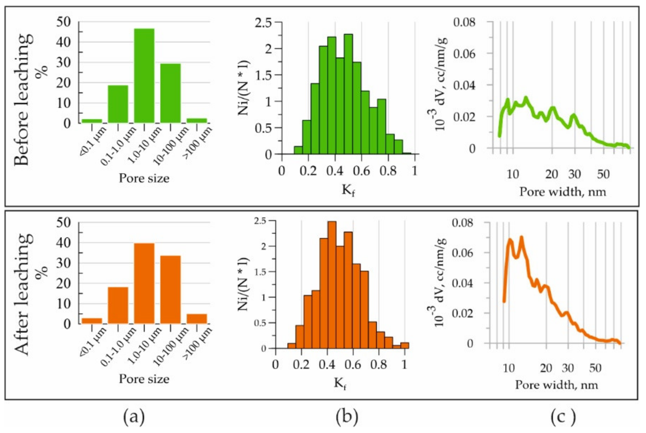
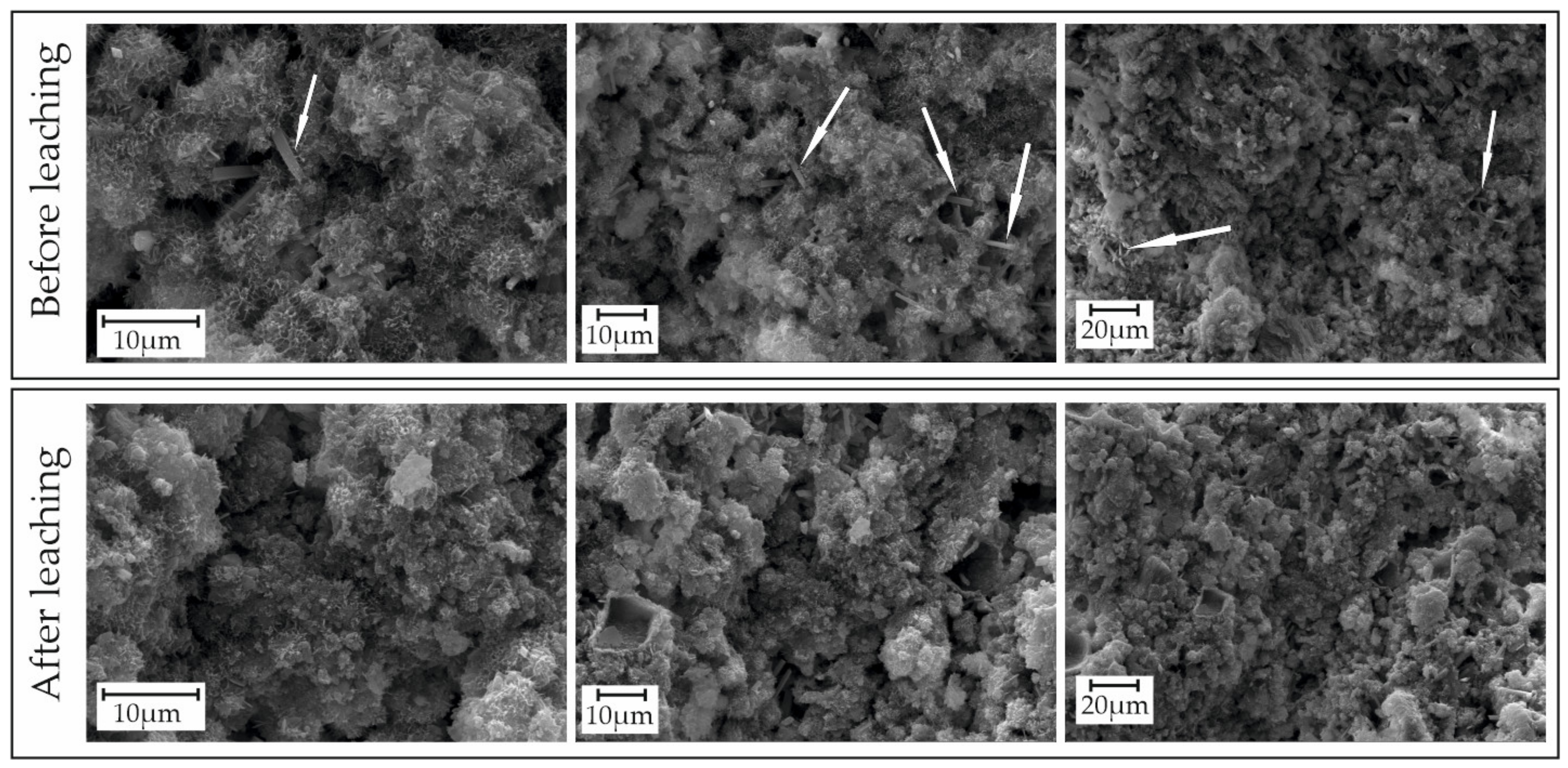
3.1. Changes in the Structure of the Pore Space of Concrete during Leaching Experiments

The porosity of the concrete was studied by a set of methods—μCT, SEM, and low-temperature nitrogen adsorption, which made it possible to consider a larger range of pore sizes. To observe changes in the porosity of the concrete, the same sample was used, taken before and after the experiment (Figure 2a). When processing the μCT data, a region with relatively low X-ray density was identified, which corresponded to the pores in the sample body (Figure 2b).
According to the results of the analysis, it was found that the porosity (macropores) in the concrete sample before and after leaching increased from 29.23% of the volume to 34.80% (Figure 2c—areas are highlighted in yellow in the model, corresponding to the pores in the body of the sample by X-ray density). The largest increase in pores was reliably recorded in the edge part of the sample, while no changes were observed in the central part. This is most likely due to the short duration and static conditions of the experiment; the central zones were not affected by the leaching processes. At the same time, the average sizes of the pores and particles differed markedly from sample to sample (three duplicates were involved in the experiment), which can be explained by the high heterogeneity of the initial cement material (cementing conditions were strictly kept the same for all samples). Thus, it was decided to study the changes in the porosities of the cements by the CT and SEM methods in the same samples before and after leaching, considering the central zone was unchanged and the marginal zone was changed.
Along with the change in the total porosity observed by the CT method, there was also a change in the pore morphology, traced by the SEM method. Figure 3b presents data on the change in the probability density (Ni/(N * l)) of the form factor distribution (Kf), obtained using SEM followed by analysis of the obtained images in one of the modules of the STIMAN program for complex quantitative morphological analysis of the microstructure of solids [65]. Kf is defined as the ratio of the area to the perimeter of the pore in the SEM image. The Kf of a circle is equal to 1. According to the presented histograms, it can be seen that in the edge part of the concrete sample, exposed to synthetic water, the shape of the pores is more spherical than in the central part, where leaching is practically not observed. At the same time, the maximum equivalent pore diameter (D) (equivalent pore diameter is the diameter of a circle equal in area to the analyzed pore) in the edge zone increased significantly compared to the central part, from 162 µm to 259 µm. In this case, the change in the contribution of pores of different categories to the total porosity of the sample is more complex: the contribution to the total porosity of pores with D > 10 µm increased during the experiment, and the contribution of pores D = 1–10 µm decreased (Figure 3a).
The surface characteristics and micro-mesoporosity of the concrete samples were determined using low-temperature nitrogen adsorption on a Quadrasorb SI/Kr unit (Table 1). The samples were crushed prior to testing. That is, as a result of using the method, it became possible to observe changes in the microporosity (interparticle interactions) to which other methods are not sensitive. It was found that during the experiments, there was an increase in the surface area of the concrete by about 1.4 times, and the volume of the pore space by 1.2 times, while the average pore size decreased by 2.3 times. Pores with sizes of <2 nm (micropores, according to the IUPAK classification [66]) were absent both in the original concrete sample and after leaching under the specified conditions.
As can be seen from the data presented in Figure 3c (concrete before leaching), the pore diameter of the original concrete ranged from 8 to 80 nm, and pores with a diameter of 10 to 40 nm predominate. In this case, the maxima in the pore size distribution were observed in the ranges of 19–22 nm and 27–31 nm. Thus, the surface of the original concrete contains mainly mesopores, as well as a number of macropores. Comparing the diagrams in Figure 3c, one can note an increase in the volume of pores with a width of 10–20 nm, while the volume of the remaining pores does not change.
Thus, under the influence of model waters, new pores with sizes of 10 to 20 nm were formed, which led to an increase in the volume of the pore space and the surface area of the concrete. This indicates the leaching of concrete components.
Summing up the impact of the model water of the crystalline rock of the Yeniseyskiy site on concrete, it can be noted that in concrete, as a result of leaching, increases in the numbers of both macro- and mesopores occurred, and their size distribution changed towards an increase in the pores in the range of 10–100 µm for the macropores and 10–20 nm for the mesopores. This happened due to the dissolution of part of the phases, mainly in the marginal part of the concrete samples. However, it should be noted that there were no large changes in the surface characteristics of the concrete, which may indicate a low intensity of the leaching processes, confirming the research data [16]. Based on the composition of the model waters before and after leaching (see Table 2), it can be assumed that the main leaching mechanism was the dissolution of the concrete components, as shown below.

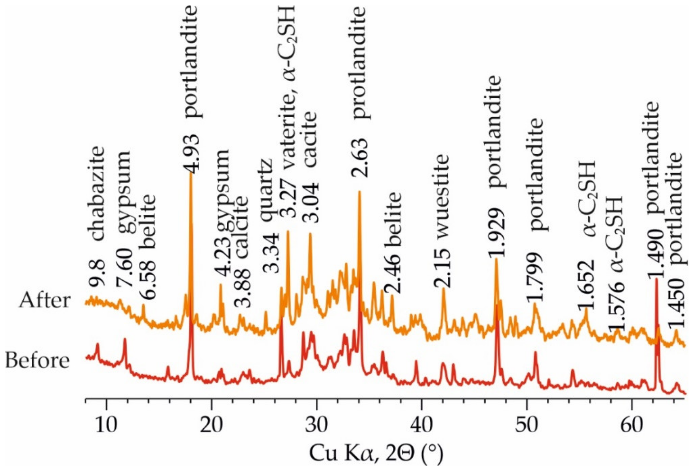
3.2. Change in Concrete Composition during Leaching Experiments

Analyzing the changes in the composition of the synthetic water after the experiments on leaching concrete, increases in the concentrations of sodium, potassium, aluminum, and silicon, and decreases in the contents of magnesium, calcium, chlorine, and sulfur are clearly noticeable (Table 2).
As a result of interaction with the concrete for 30 days, the pH of the solution increased from 6.11 to 12.1.
According to the results of the analysis of the chemical composition of the solid component (Table 3) in the samples after leaching, decreases in the contents of sodium and potassium, and slight increases in aluminum, silicon, magnesium, and iron were noted.
The phase composition is presented in Table 4. Before the experiment, the composition of the concretes was dominated by phases diagnosed by a series of reflections—vaterite, calcite, portlandite, belite, larnite, chabasite, magnetite, quartz, alite, gypsum, gismondite, dolomite, α-C2SH, alunite, wustite, and others. After the leaching of the concrete samples, there was a decrease in the number of the main phases, namely vaterite, portlandite, and gypsum, while the contents of α-C2SH, alite, and belite increased. The appearances of afwillite and nordstrandite, which were not previously present in the sample, were also noted. In Figure 4, the main reflections are marked and the phases related to these reflections are labeled. The dissolution of phases was also well diagnosed by the data of the scanning electron microscopy, illustrated in Figure 5.

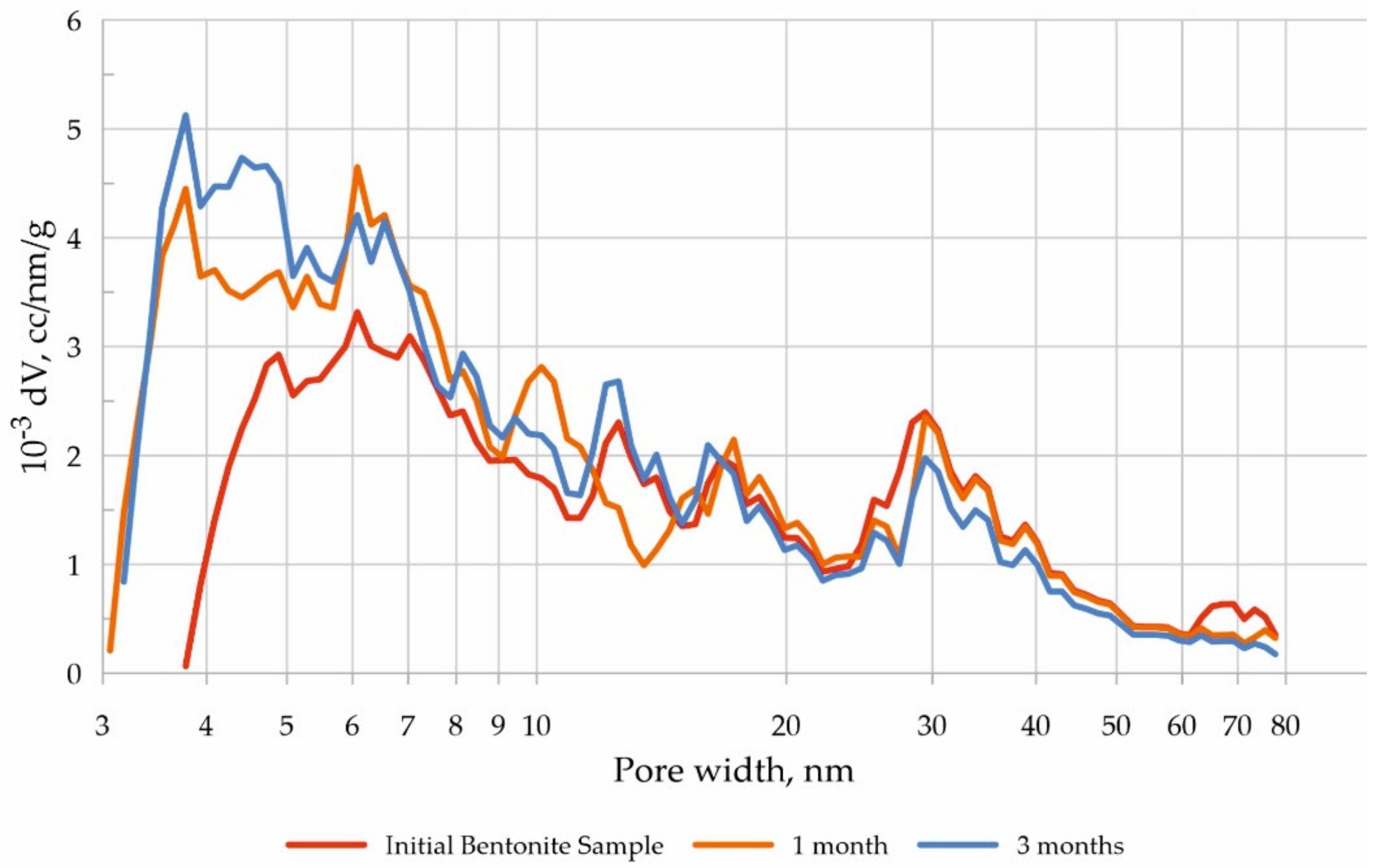
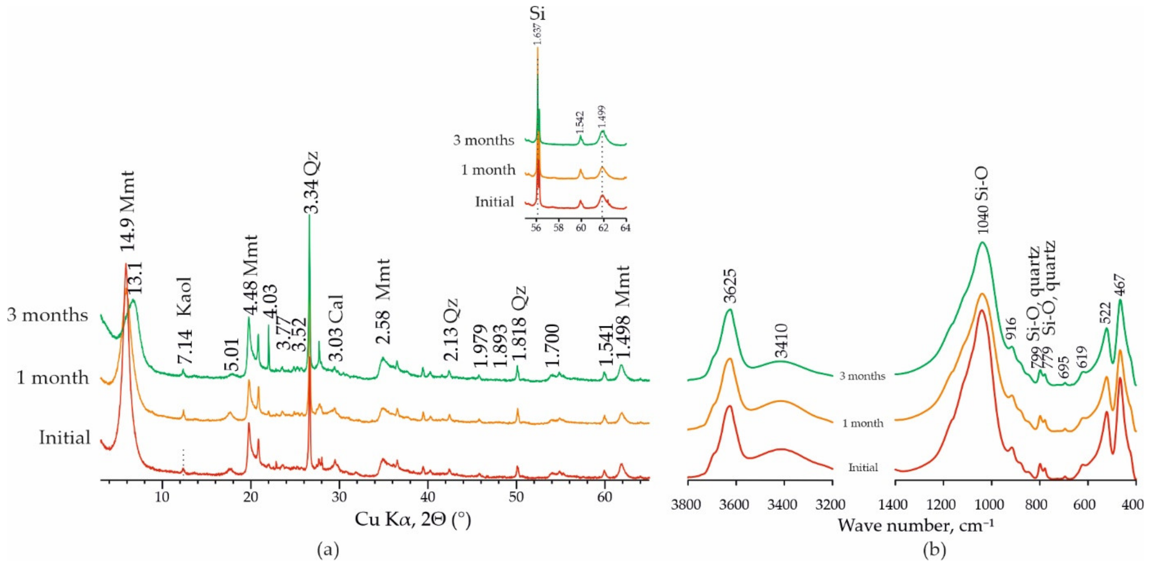
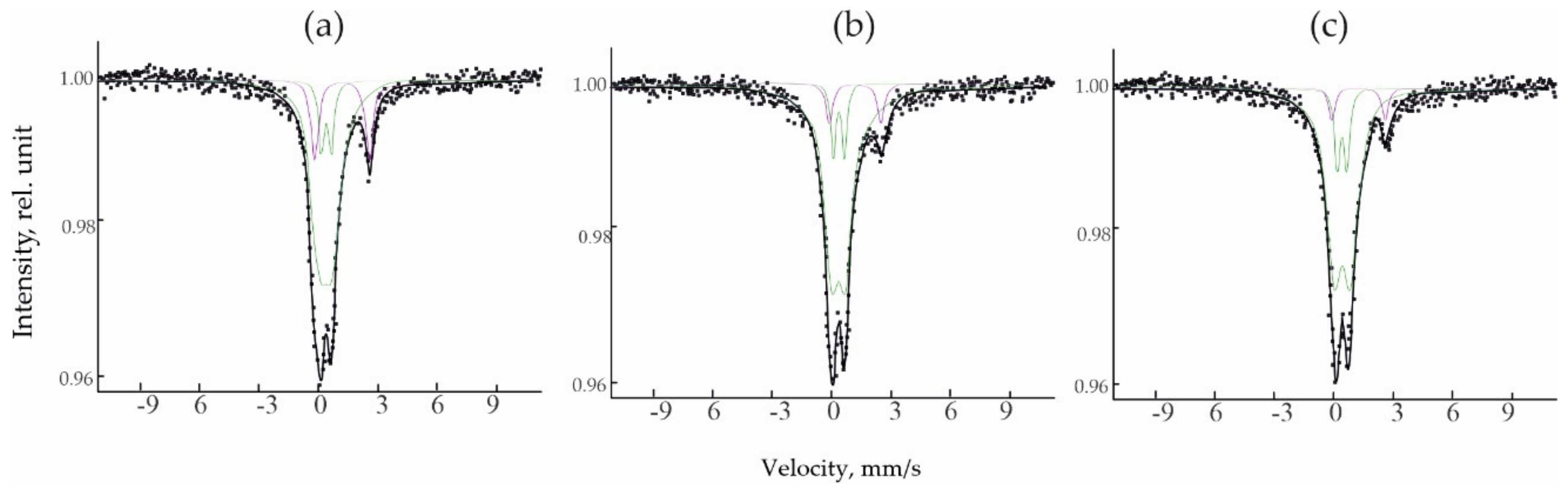
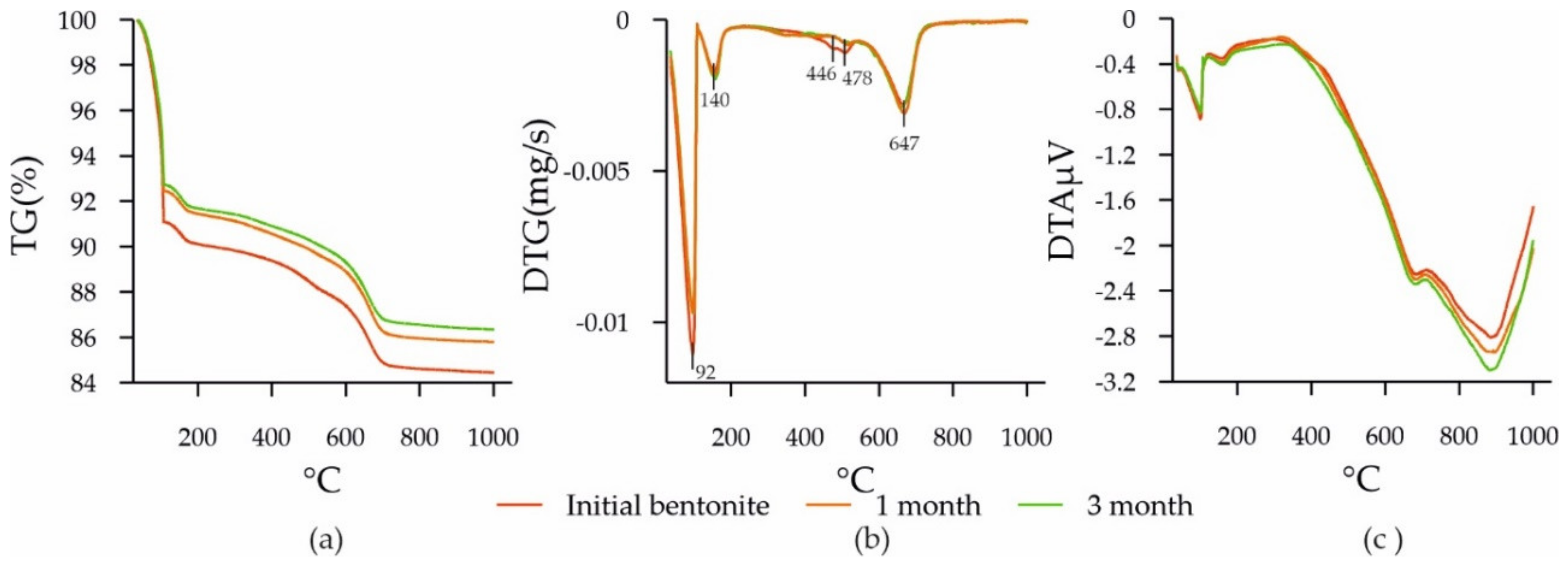
3.3. Changes in the Composition and Structure of Bentonite during Experiments

The long-term interaction of bentonite with the synthetic water solutions after leaching of concrete led to an increase in the specific surface area by almost 1.5 times; at the same time, the pore volume practically did not change. The displacement of the pore distribution to the side of a lower pore width as well as a reduction in the macropore quantity (>50 nm), leading to a decrease in the average pore size from 6 to 4 nm, was observed after the analysis of pore distribution (Figure 6).
In the region of (001) reflections, a slight shift was observed from 14.9 Å in the natural bentonite to 13.1 Å after treatment for 3 months (Figure 7a). Moreover, after prolonged exposure, the half-width and the intensity of the reflections changed. According to the data of chemical analysis (Table 5), the contents of calcium, potassium, and sodium in the bentonites in the course of the experiments increased, which may indicate, among other things, a change in the composition of the exchange cations. Probably, the substitution of predominantly divalent exchangeable cations (Mg) for monovalent (Na, K) took place simultaneously with a change in the nature of the interaction of particles with each other as a result of prolonged contact with highly alkaline solutions. The latter led to a decrease in the ordering in the smectite structure and to a change in the profile of the 001 line.
During the experiments, the bentonite was exposed to high temperatures and a highly alkaline medium (the pH of the solution at the time of the experiment was 12.1). High pH values affected the colloidal properties of the smectites, which manifested in the degree of orientation of the clay particles in the plane of the substrate of the preparation for X-ray photography and in the degree of order in the superposition of montmorillonite layers in the composition of the particles. Both the pH of the medium and the duration of exposure affected the solubility of various components of the bentonite.
In terms of the qualitative mineral composition, the original bentonite corresponded to the commercial sample of the bentonite studied in the article by [58]. The smectite content in the sample was 64.3 wt% (Table 6). In the course of interaction with the leached concrete, the contents of quartz, feldspars, anatase, kaolinite, siderite, and calcite decreased. The relative amount of smectite in the samples increased by 4.2 wt%.
The decrease in the content of SiO2 in the composition of bentonites indicates the dissolution of quartz, and the increase in Al2O3 indicates a relative increase in montmorillonite in the composition of the solid component, which was also confirmed by the data of mineral analysis (Table 5).
When studying the structure of smectites and, in general, 2:1 clay minerals, the shapes and positions of the profile in the region of reflections (060), which appear in the range of angles 61–63° 2Θ when using CuKα, acquire a special role in the interpretation of possible structural transformations. To clarify the position of the 060 reflection, the samples were taken using an internal standard. Si was used as a reference with the position of the reflection (311) at an angle of 56.119° 2Θ. To better visualize the observed changes, the 55–64° 2Θ range was examined on a larger scale. In the decomposition and fitting of the intensity peaks in the 060 smectite region in the Fityk program (version 1.3.1) [67] the contribution of CuKα2 was taken into account. According to the results of this analysis, it was concluded that the original sample only had a reflection at d = 1.499 Å, which corresponds to the position of the 060 reflection for montmorillonite. The position of the 060 reflection for the samples after 1 and 3 months of treatment was preserved, while no additional peaks were observed in the region of smaller angles. This indicates the formation of trioctahedral smectite.
The FTIR spectroscopic study of the natural sample of bentonite confirmed that it was mainly composed of dioctahedral Al-rich smectite montmorillonite (Figure 7b). This is evidenced by the combination of the following characteristics of the IR spectra: the most intense band of Si–O stretching was relatively symmetrical and located at 1040 cm−1, with a doublet at 522 cm−1 (Al–O–Si deformation) and at 467 cm−1 (Si–O–Si deformation); the OH stretching bands occurred at 3625 cm−1. The absorption band near 619 cm−1, attributed to the coupled Al–O and Si–O out-of-plane vibrations, shows the high octahedral Al content, while the bands at 881 and 850 cm−1 indicate octahedral substitutions of Fe for Al, and of Mg for Al, respectively [68,69,70,71].
At the same time, the analysis of the change in the absorption bands of the samples exposed for 1 and 3 months to the water used for leaching the concrete at an elevated temperature shows that the short-range order bonds that are characteristic of dioctahedral smectites did not undergo changes in the course of the experiments. Thus, it can be concluded that the observed changes in the composition of the octahedral networks were weakly manifested and could hardly have a strong effect on the changes in the physicochemical and physicomechanical properties of the bentonites from the 10th Khutor deposit under the conditions of the DRW.
The Mossbauer spectroscopic study of the treated bentonite samples (1 month and 3 months) confirm that the structures of these samples are similar—the parameters of the spectra had very close values (Table 7, Figure 8). The natural (initial) untreated sample had a higher Fe2+/Fe3+ ratio. Thus, under the influence of synthetic waters, Fe2+ was oxidized in octahedral positions, and then the structure remained stable.
To analyze changes in the structure of smectite, a thermal analysis of the bentonite samples was carried out. Two endothermic effects characteristic of smectites were observed (Figure 9). The first, located in the range from 80 to 194 °C, is associated with dehydration due to the removal of adsorbed and interlayer water [72]. The peak of dehydration at around 140 °C corresponds to the presence of alkaline earth cations in the interlayer space of smectite [73]. The second endothermic effect is associated with the loss of smectite structural water; it changed from 647 °C for the original bentonite to 643 °C for the bentonite that had been exposed to the concrete leaching for 3 months. These changes may be associated with minor changes in the positions of hydroxyls in the octahedral networks of smectites.
Endothermic effects in the regions of 446 and 478 °C traced in the original bentonite decreased in the bentonites after 1 and 3 months of the experimental exposure conditions. These effects are associated with the impurity minerals of bentonites, such as kaolinite and carbonates (siderite), which were destroyed during the experiment. This was also confirmed by the X-ray diffraction data (Table 6). The total weight loss of the original bentonite decreased and amounted to 15.6% in the original, 14.2% after 1 month, and 13.6% after 3 months, which correlates with the loss of impurity minerals during the experiment.
In general, according to the TG, DTG, and DTA data, there were no visible noticeable changes in the structure of the smectite.

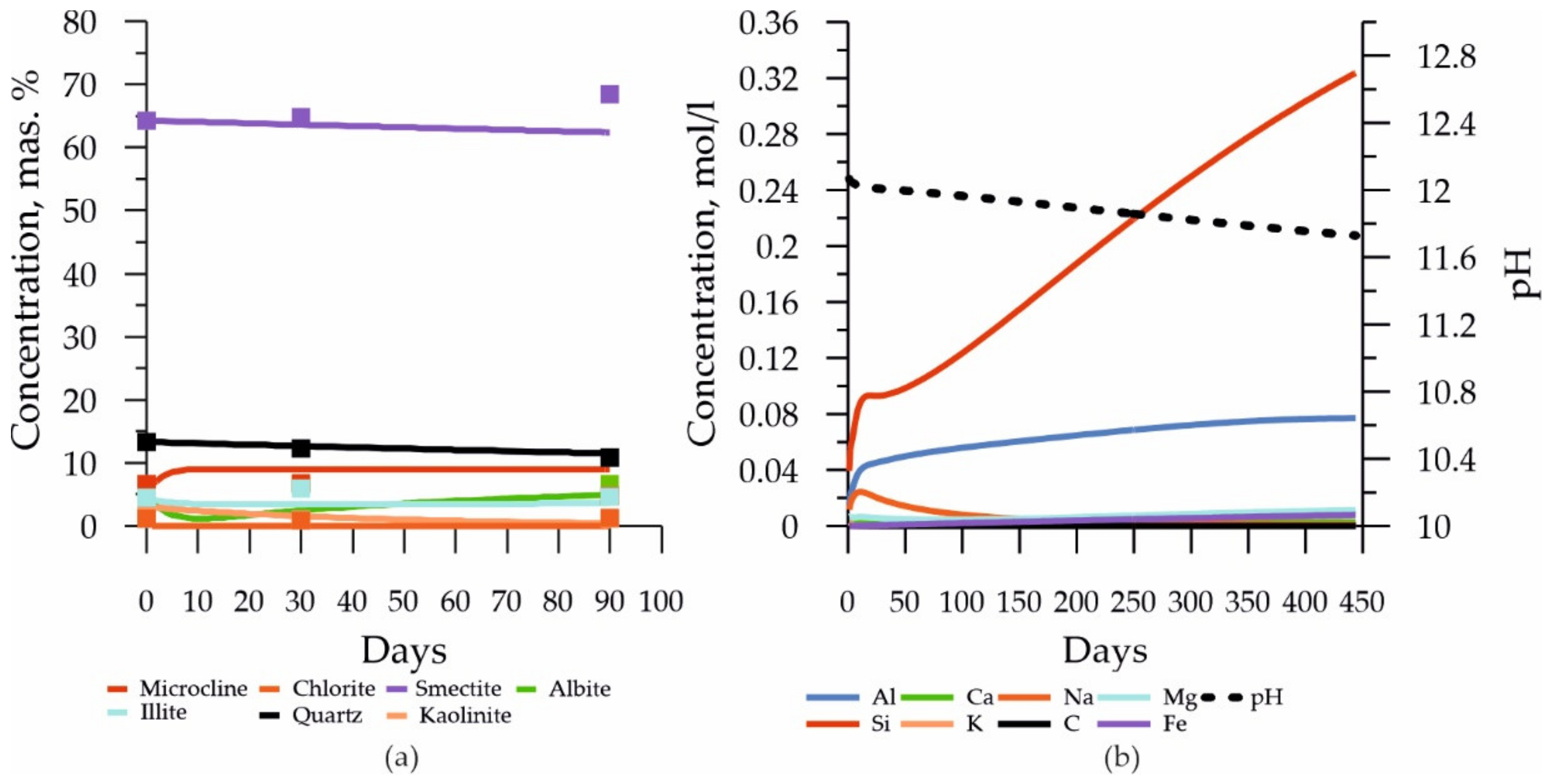
3.4. Modeling of Bentonite Evolution Experiment

As model bentonite, we used bentonite from the 10th Khutor deposit described by the structural formula (NaCaMg) (Al1.46Fe3+0.16Fe2+0.04Mg0.34)[Si3.83Al0.17] (OH)2 [57]. It was assumed in the model that the composition of the pore water, initially in equilibrium with the bentonite was a pH of 8.5, Al 3.17 × 10⁻⁵ mol/L, C 3.93 × 10⁻³ mol/L, Ca 5.01 × 10⁻⁴ mol/L, Cl 5.64 × 10⁻⁴ mol/L, Mg 3.42 × 10⁻⁴ mol/L, Na 1.74 × 10⁻³ mol/L, S 3.12 × 10⁻⁴ mol/L, Si 4.99 × 10⁻⁵ mol/L, K 10 × 10−4 mol/L, and Fe 1 × 10⁻⁵ mol/L. In the model, ion exchange was also taken into account (CEC = 10 2 meq/100 g).
The results of modeling the transformation of smectite from the 10th Khutor deposit, as well as a comparison with the experimental data, are shown in Figure 10a. The parametrization of the model is given in Table 8, according to [54]. The simulation was carried out in the code PhreeqC 2.18 [64]; the database used was PK PhreeqC llnl.dat.
The results show that the studied bentonite has high stability; the calculated values of the solubility constants in the dissolution equation (see calibrated values) are significantly lower than the literature values [54], including according to the dissolution model [74,75].
A forecast of the evolution of bentonite as function of chemical composition was also carried out with the obtained parametrization of the model for 450 days. The results are shown in Figure 10b. A relatively small transformation of smectite, a decrease in the content of quartz, and an increase in the content of microcline are clearly visible. The content of albite initially dropped sharply, then, at the end of the first week, an increase in its content in the system was observed. Kaolinite almost completely transformed into other clay materials in the models. A feature of the model behavior of illite was a certain drop in its content, which was replaced by an increase in its amount in the system—a pattern of illitization began to be observed.
The results obtained indicate the high stability of the studied bentonite from the 10th Khutor deposit, which can be recommended for use as a material for engineering safety barriers.

4. Conclusions

Transformations at the concrete–bentonite boundary are important in assessing the safety of radioactive waste disposal in geological formations. In the course of experiments on the effect of model water of a crystalline massif at the Yeniseisky site (Krasnoyarsk Region) at an elevated temperature (90 °C), it was revealed that as a result of leaching from concrete, a number of crystalline phases, such as vaterite, portlandite, gypsum, and ettringite, were observed, along with a slight increase in the porosity of the concrete, and the transition to a solution of cations Na, Al, Si, K, which then interacted with the bentonite.
The bentonite exposed to a concrete-leached groundwater solution at elevated temperature differed from the initial sample by means of the pore volume distribution displacement towards lower pore sizes and the decreased volume of the macropores, which caused an average pore size reduction from 6 to 4 nm.
An increase in the pH and, in addition, fluctuations in the number of cations in the composition of the solution, led to changes in both the composition of bentonite itself due to the dissolution of quartz, feldspars, and siderite, and to the transformation of the composition of montmorillonite. Octahedral Fe2+ in the structure of the initial sample was oxidized during the treatment in the first step (1 month), and then the structure remained stable.
Geochemical modeling showed that the considered bentonite is highly stable. We have developed a model for the evolution of the studied bentonite based on our experimental data, which takes into account the kinetically controlled phase transitions of bentonite, as well as ion exchange. Evolution models should be built for each individual bentonite on the basis of experimental studies since, for example, as in this case, the use of the literature values of the model parameters would lead to inadequate results, showing a higher rate of change than what was observed experimentally.
It can be expected that the properties of bentonite will undergo changes after contact with highly alkaline solutions from the leaching of concrete, which requires additional studies, including long-term ones.

Author Contributions

Conceptualization, I.M. and V.K.; validation, I.M., M.C., E.T. and V.K.; methodology, formal analysis, I.M., S.Z., P.K., O.Z., M.R., K.B., M.C., E.T. and T.Z.; investigation, I.M., S.Z., P.K., O.Z., M.R., M.C., K.B., E.T., T.Z. and V.K.; data curation, I.M.; writing—original draft preparation, I.M.; visualization, I.M., M.C., K.B., E.T., T.Z. and V.K.; supervision, V.K.; project administration, V.K.; funding acquisition, V.K. All authors have read and agreed to the published version of the manuscript.

Funding

The reported study was funded by Russian Foundation for Basic Research (RFBR) according to the research project No. 20-35-90039. Modeling was carried out as part of the implementation of the State Contract of the Ministry of Education and Science No. 0046-2019-0004.

Institutional Review Board Statement

Not applicable.

Informed Consent Statement

Not applicable.

Data Availability Statement

Not applicable.

Acknowledgments

The authors thank Ruslan Kuznetsov (MSU, Geological Faculty) for providing the μCT data. The experimental studies were partially carried out using the equipment acquired with funding from the Lomonosov Moscow State University Development Program (X-ray Diffractometer Ultima-IV, Rigaku, Scanning Electron Microscope LEO 1450VP, Carl Zeiss, and X-ray CT scanner Yamato TDM1000, Yamato Scientific) and the Development Program of the Interdisciplinary Scientific and Educational School of the Lomonosov Moscow State University—Future Planet and Global Environmental Change (TGA/DSC 3+, Mettler Toledo).

Conflicts of Interest

The authors declare no conflict of interest.

References

  1. Scientific and Technical Basis for the Geological Disposal of Radioactive Wastes; Technical Reports Series; International Atomic Energy Agency: Vienna, Austria, 2003.
  2. Sellin, P.; Leupin, O.X. The Use of Clay as an Engineered Barrier in Radioactive-Waste Management a Review. Clays Clay Miner. 2013, 61, 477–498. [Google Scholar] [CrossRef]
  3. Tsebakovskaya, N.S.; Utkin, S.S.; Kapyrin, I.V.; Medyantsev, N.V.; Shamina, A.V. Review of Foreign Practices for Disposal of Spent Nuclear Fuel and Radioactive Waste; Komtekhprint: Moscow, Russia, 2015. [Google Scholar]
  4. Dixon, D.; Sandén, T.; Jonsson, E.; Hansen, J. Backfilling of Deposition Tunnels: Use of Bentonite Pellets; Swedish Nuclear Fuel and Waste Management Co.: Stockholm, Sweden, 2011. [Google Scholar]
  5. Boerjesson, L.; Gunnarsson, D.; Johannesson, L.-E.; Jonsson, E. Design, Production and Initial State of the Buffer; Swedish Nuclear Fuel and Waste Management Co.: Stockholm, Sweden, 2010. [Google Scholar]
  6. Keto, P.; Dixon, D.; Jonsson, E.; Gunnarsson, D. R-09-52 Assessment of Backfill design for KBS-3V Repository; Swedish Nuclear Fuel and Waste Management Co.: Stockholm, Sweden, 2009. [Google Scholar]
  7. Fries, T.; Claudel, A.; Weber, H.; Johnson, L.; Leupin, O. The Swiss concept for the disposal of spent fuel and vitrified HLW. In Proceedings of the International Technical Conference on the Practical Aspects of Deep Geological Disposal of Radioactive Waste, Prague, Czech Republic, 16–18 June 2008; pp. 45–53. [Google Scholar]
  8. Kaufhold, S.; Dohrmann, R. Distinguishing between more and less suitable bentonites for storage of high-level radioactive waste. Clay Miner. 2016, 51, 289–302. [Google Scholar] [CrossRef] [Green Version]
  9. Birgersson, M.; Hedström, M.; Karnland, O.; Sjöland, A. Bentonite buffer: Macroscopic performance from nanoscale properties. In Geological Repository Systems for Safe Disposal of Spent Nuclear Fuels and Radioactive Waste; Apted, M.J., Joonhong, A., Eds.; Woodhead Publishing: Sawston, UK, 2017; pp. 319–364. ISBN 9781845699789. [Google Scholar]
  10. Krupskaya, V.V.; Zakusin, S.V.; Lekhov, V.A.; Dorzhieva, O.V.; Belousov, P.E.; Tyupina, E.A. Buffer Properties of Bentonite Barrier Systems for Radioactive Waste Isolation in Geological Repository in the Nizhnekanskiy Massif. Radioact. Waste 2020, 1, 35–55. [Google Scholar] [CrossRef]
  11. Karnland, O.; Olsson, S.; Nilsson, U. Mineralogy and Sealing Properties of Various Bentonites and Smectite-Rich Clay Materials; SKB Technical Report TR-06-30; Swedish Nuclear Fuel and Waste Management Co.: Stockholm, Sweden, 2006; pp. 1–112. [Google Scholar]
  12. A Review of the Development of Bentonite Barriers in KBS-3V Disposal Concept; Harwell: Oxford, UK, 2014.
  13. Krupskaya, V.V.; Biryukov, D.V.; Belousov, P.E.; Lekhov, V.A.; Romanchuk, A.Y.; Kalmykov, S.N. The use of natural clay materials to increase the nuclear and radiation safety level of nuclear legacy facilities. Radioact. Waste 2018, 2, 30–43. [Google Scholar]
  14. Dorofeev, A.N.; Bolshov, L.A.; Linge, I.I.; Utkin, S.S.; Saveleva, E.A. Strategic Master Plan for R&D Demonstrating the Safety of Construction, Operation and Closure of a Deep Geological Disposal Facility for Radioactive Waste. Radioact. Waste 2017, 1, 33–41. [Google Scholar]
  15. Bogatov, S.A.; Kryuchkov, D.V.; Pavlov, D.I.; Sychenko, D.V. Analysis of Various Concepts for RW Class 1 Disposal in Crystalline Rocks. Radioact. Waste 2020, 12, 66–77. [Google Scholar] [CrossRef]
  16. Alonso, M.C.; García Calvo, J.L.; Cuevas, J.; Turrero, M.J.; Fernández, R.; Torres, E.; Ruiz, A.I. Interaction processes at the concrete-bentonite interface after 13 years of FEBEX-Plug operation. Part I: Concrete alteration. Phys. Chem. Earth 2017, 99, 38–48. [Google Scholar] [CrossRef]
  17. Fernández, R.; Torres, E.; Ruiz, A.I.; Cuevas, J.; Alonso, M.C.; García Calvo, J.L.; Rodríguez, E.; Turrero, M.J. Interaction processes at the concrete-bentonite interface after 13 years of FEBEX-Plug operation. Part II: Bentonite contact. Phys. Chem. Earth 2017, 99, 49–63. [Google Scholar] [CrossRef]
  18. Robineau, M.; Deydier, V.; Crusset, D.; Bellefleur, A.; Neff, D.; Vega, E.; Sabot, R.; Jeannin, M.; Refait, P. Formation of iron sulfides on carbon steel in a specific cement grout designed for radioactive waste repository and associated corrosion mechanisms. Materials 2021, 14, 3563. [Google Scholar] [CrossRef]
  19. The Scientific Foundations of Deep Geological Disposal; United Kingdom Nirex Limited: Harwell, UK, 2001; p. 118.
  20. IAEA. The Behaviours of Cementitious Materials in Long Term Storage and Disposal of Radioactive Waste: Results of a Coordinated Research Project; IAEA: Vienna, Austria, 2013; ISBN 9789201393104. [Google Scholar]
  21. Bogatov, S.A. Disposal of in Verticale Deposition Holes with Cement Backfill—Pro and Contra with Regard to Long Term Safety of Geological Disposal Facility. Radioact. Waste 2018, 1, 21–33. [Google Scholar]
  22. Dickinson, M.; Holton, D.; Cairns, M. Development of Understanding of Disposability of High-Heat-Generating Wastes in the UK. In Proceedings of the WM2015 Conference, Phoenix, AR, USA, 15–19 March 2015; p. 13. [Google Scholar]
  23. García Calvo, J.L.; Hidalgo, A.; Alonso, C.; Fernández Luco, L. Development of low-pH cementitious materials for HLRW repositories: Resistance against ground waters aggression. Cem. Concr. Res. 2010, 40, 1290–1297. [Google Scholar] [CrossRef]
  24. Kozlov, P.V.; Gorbunova, O.A. Cementing as a Method of Radioactive Waste Immobilization; Kozlov, P.V., Gorbunova, O.A., Eds.; PO “Mayak”: Ozersk, Russia, 2011; ISBN 978-5-903159-30-7. [Google Scholar]
  25. Ochs, M.; Mallants, D.; Wang, L. Radionuclide and Metal Sorption on Cement and Concrete (Topics in Safety, Risk, Reliability and Quality); Springer International Publishing: Cham, Switzerland, 2016; ISBN 978-3-319-23650-6. [Google Scholar]
  26. Jacques, D.; Wang, L.; Martens, E.; Mallants, D. Time Dependence of the Geochemical Boundary Conditions for the Cementitious Engineered Barriers of the Belgian Surface Disposal Facility. Project Near Surface Disposal of Category A Waste at Dessel NIRAS-MP5-03 DATA-LT(NF). Version 1.; NIROND-TR. 2009. Available online: https://www.researchgate.net/profile/Dirk-Mallants/publication/248708031_Time_dependence_of_the_geochemical_boundary_conditions_for_the_cementitious_engineered_barriers_of_the_Belgian_surface_disposal_facility/links/0deec51e155c435821000000/Time-dependence-of-the-geochemical-boundary-conditions-for-the-cementitious-engineered-barriers-of-the-Belgian-surface-disposal-facility.pdf (accessed on 19 December 2021).
  27. Zakusin, S.V.; Krupskaya, V.V.; Dorzhieva, O.V.; Tyupina, E.A.; Zhuhlistov, A.P. Modification of the adsorption properties of montmorillonite by the thermochemical treatment. Sorption Chromatogr. Process. 2015, 15, 874–883. [Google Scholar]
  28. Krupskaya, V.V.; Zakusin, S.V.; Tyupina, E.A.; Dorzhieva, O.V.; Chernov, M.S.; Bychkova, Y. V Transformation of Structure and Adsorption Properties of Montmorillonite under Thermochemical Treatment. Geochemistry Int. 2019, 57, 314–330. [Google Scholar] [CrossRef]
  29. Krupskaya, V.; Novikova, L.; Tyupina, E.; Belousov, P.; Dorzhieva, O.; Zakusin, S.; Kim, K.; Roessner, F.; Badetti, E.; Brunelli, A.; et al. The influence of acid modification on the structure of montmorillonites and surface properties of bentonites. Appl. Clay Sci. 2019, 172, 1–10. [Google Scholar] [CrossRef]
  30. Krupskaya, V.V.; Zakusin, S.V.; Tyupina, E.A.; Dorzhieva, O.V.; Zhukhlistov, A.P.; Belousov, P.E.; Timofeeva, M.N. Experimental study of montmorillonite structure and transformation of its properties under treatment with inorganic acid solutions. Minerals 2017, 7, 49. [Google Scholar] [CrossRef]
  31. Kaufhold, S.; Dohrmann, R.; Ufer, K.; Kober, F. Interactions of bentonite with metal and concrete from the FEBEX experiment: Mineralogical and geochemical investigations of selected sampling sites. Clay Miner. 2018, 53, 745–763. [Google Scholar] [CrossRef] [Green Version]
  32. Sánchez, L.; Cuevas, J.; Ramírez, S.; Riuiz De León, D.; Fernández, R.; Vigil Dela Villa, R.; Leguey, S. Reaction kinetics of FEBEX bentonite in hyperalkaline conditions resembling the cement-bentonite interface. Appl. Clay Sci. 2006, 33, 125–141. [Google Scholar] [CrossRef]
  33. Ramírez, S.; Cuevas, J.; Vigil, R.; Leguey, S. Hydrothermal alteration of “La Serrata” bentonite (Almeria, Spain) by alkaline solutions. Appl. Clay Sci. 2002, 21, 257–269. [Google Scholar] [CrossRef]
  34. Savage, D.; Bateman, K.; Hill, P.; Hughes, C.; Milodowski, A.; Pearce, J.; Rae, E.; Rochelle, C. Rate and mechanism of the reaction of silicates with cement pore fluids. Appl. Clay Sci. 1992, 7, 33–45. [Google Scholar] [CrossRef]
  35. Liu, L.N.; Chen, Y.G.; Ye, W.M.; Cui, Y.J.; Wu, D.B. Effects of hyperalkaline solutions on the swelling pressure of compacted Gaomiaozi (GMZ) bentonite from the viewpoint of Na+ cations and OH– anions. Appl. Clay Sci. 2018, 161, 334–342. [Google Scholar] [CrossRef]
  36. Kaufhold, S.; Dohrmann, R. Stability of bentonites in salt solutions III—Calcium hydroxide. Appl. Clay Sci. 2011, 51, 300–307. [Google Scholar] [CrossRef]
  37. Karnland, O.; Olsson, S.; Nilsson, U.; Sellin, P. Experimentally determined swelling pressures and geochemical interactions of compacted Wyoming bentonite with highly alkaline solutions. Phys. Chem. Earth 2007, 32, 275–286. [Google Scholar] [CrossRef]
  38. Fernández, R.; Rodríguez, M.; de la Villa, R.V.; Cuevas, J. Geochemical constraints on the stability of zeolites and C-S-H in the high pH reaction of bentonite. Geochim. Cosmochim. Acta 2010, 74, 890–906. [Google Scholar] [CrossRef]
  39. Fernández, R.; Ruiz, A.I.; Cuevas, J. The role of smectite composition on the hyperalkaline alteration of bentonite. Appl. Clay Sci. 2014, 95, 83–94. [Google Scholar] [CrossRef]
  40. Cuisinier, O.; Masrouri, F.; Pelletier, M.; Villieras, F.; Mosser-Ruck, R. Microstructure of a compacted soil submitted to an alkaline PLUME. Appl. Clay Sci. 2008, 40, 159–170. [Google Scholar] [CrossRef]
  41. Cuevas, J.; Fernández, R.; Sánchez, L.; Vigil de la Villa, R.; Rodríguez, M.; Leguey, S. Reactive Diffusion Front Driven by an Alkaline Plume in Compacted Mg—Homoionic Bentonite. pp. 1–2. 2007. Available online: https://www.andra.fr/mini-sites/lille2007/abstract_lille2007/donnees/pdf/509_510_P_MTPM_44.pdf (accessed on 24 December 2021).
  42. Claret, F.; Bauer, A.; Schäfer, T.; Griffault, L.; Lanson, B. Experimental investigation of the interaction of clays with high-pH solutions: A case study from the Callovo-Oxfordian formation, Meuse-Haute Marne underground laboratory (France). Clays Clay Miner. 2002, 50, 633–646. [Google Scholar] [CrossRef]
  43. Bauer, A.; Lanson, B.; Ferrage, E.; Emmerich, K.; Taubald, H.; Schild, D.; Velde, B. The fate of smectite in KOH solutions. Am. Mineral. 2006, 91, 1313–1322. [Google Scholar] [CrossRef] [Green Version]
  44. Anh, H.N.; Ahn, H.; Jo, H.Y.; Kim, G.Y. Effect of alkaline solutions on bentonite properties. Environ. Earth Sci. 2017, 76, 1–10. [Google Scholar] [CrossRef]
  45. Savage, D.; Benbow, S.; Watson, C.; Takase, H.; Ono, K.; Oda, C.; Honda, A. Natural systems evidence for the alteration of clay under alkaline conditions: An example from Searles Lake, California. Appl. Clay Sci. 2010, 47, 72–81. [Google Scholar] [CrossRef]
  46. Pusch, R.; Zwahr, H.; Gerber, R.; Schomburg, J. Interaction of cement and smectitic clay—Theory and practice. Appl. Clay Sci. 2003, 23, 203–210. [Google Scholar] [CrossRef]
  47. Mosser-Ruck, R.; Cathelineau, M. Experimental transformation of Na,Ca-smectite under basic conditions at 150 °C. Appl. Clay Sci. 2004, 26, 259–273. [Google Scholar] [CrossRef]
  48. Savage, D.; Noy, D.; Mihara, M. Modelling the interaction of bentonite with hyperalkaline fluids. Appl. Geochem. 2002, 17, 207–223. [Google Scholar] [CrossRef]
  49. Savage, D.; Walker, C.; Arthur, R.; Rochelle, C.; Oda, C.; Takase, H. Alteration of bentonite by hyperalkaline fluids: A review of the role of secondary minerals. Phys. Chem. Earth 2007, 32, 287–297. [Google Scholar] [CrossRef]
  50. Eberl, D.D.; Velde, B.; Mccormick, T. Synthesis of illite-smectite from smectite at Earth surface temperatures and high pH. Clay Miner. 1993, 28, 49–60. [Google Scholar] [CrossRef]
  51. Dauzeres, A.; Le Bescop, P.; Sardini, P.; Cau Dit Coumes, C. Physico-chemical investigation of clayey/cement-based materials interaction in the context of geological waste disposal: Experimental approach and results. Cem. Concr. Res. 2010, 40, 1327–1340. [Google Scholar] [CrossRef]
  52. Carlson, L.; Karnland, O.; Oversby, V.M.V.M.; Rance, A.P.; Smart, N.R.; Snellman, M.; Vähänen, M.; Werme, M.; Werme, L.O. Experimental studies of the interactions between anaerobically corroding iron and bentonite. Phys. Chem. Earth 2007, 32, 334–345. [Google Scholar] [CrossRef]
  53. González-Santamaría, D.E.; Fernández, R.; Ruiz, A.I.; Ortega, A.; Cuevas, J. High-pH/low pH ordinary Portland cement mortars impacts on compacted bentonite surfaces: Application to clay barriers performance. Appl. Clay Sci. 2020, 193, 105672. [Google Scholar] [CrossRef]
  54. Marty, N.C.M.; Claret, F.; Lassin, A.; Tremosa, J.; Blanc, P.; Madé, B.; Giffaut, E.; Cochepin, B.; Tournassat, C. A database of dissolution and precipitation rates for clay-rocks minerals. Appl. Geochem. 2015, 55, 108–118. [Google Scholar] [CrossRef]
  55. Belousov, P.E.; Krupskaya, V.V.; Zakusin, S.V.; Zhigarev, V.V. Bentonite Clays From 10Th Khutor Deposite: Features of Genesis, Composition and Adsorption Properties. Rudn. J. Eng. Res. 2017, 18, 135–143. [Google Scholar] [CrossRef] [Green Version]
  56. Belousov, P.E.; Krupskaya, V.V. Bentonite clays of Russia and neighboring countries. Georesursy 2019, 21, 79–90. [Google Scholar] [CrossRef]
  57. Belousov, P.; Chupalenkov, N.; Christidis, G.; Zakusina, O.; Zakusin, S.; Morozov, I.; Chernov, M.; Zaitseva, T.; Tyupina, E.; Krupskaya, V. Carboniferous Bentonites of 10th Khutor Deposit (Russia): Geology, Mineralogy, Genesis and Properties. Appl. Clay Sci. 2021, 215, 106308. [Google Scholar] [CrossRef]
  58. Rozov, K.B.; Rumynin, V.G.; Nikulenkov, A.M.; Leskova, P.G. Sorption of 137Cs, 90Sr, Se, 99Tc, 152(154)Eu, 239(240)Pu on fractured rocks of the Yeniseysky site (Nizhne-Kansky massif, Krasnoyarsk region, Russia). J. Environ. Radioact. 2018, 192, 513–523. [Google Scholar] [CrossRef] [PubMed]
  59. Meleshyn, A.Y.A.Y.; Zakusin, S.V.; Krupskaya, V.V. Swelling pressure and permeability of compacted bentonite from 10th khutor deposit (Russia). Minerals 2021, 11, 742. [Google Scholar] [CrossRef]
  60. Sokolov, V.N.; Yurkovets, D.I.; Razgulina, O.V. Study of soil microstructure using computer analysis of SEM images. Geoekologia. Inzhenernaya Geol. Gidrogeol. Geokriol. 2008, 4, 377–382. [Google Scholar]
  61. Moore, D.M.; Reynolds, R.C.J. X-ray Diffraction and the Identification and Analysis of Clay Minerals, 2nd ed.; Oxford University Press: Oxford, UK, 1999. [Google Scholar]
  62. Post, J.E.; Bish, D.L. Rietveld refinement of crystal structures using powder X-ray diffraction data. Rev. Mineral. 1989, 20, 277–308. [Google Scholar] [CrossRef]
  63. Doebelin, N.; Kleeberg, R. Profex: A graphical user interface for the Rietveld refinement program BGMN. J. Appl. Crystallogr. 2015, 48, 1573–1580. [Google Scholar] [CrossRef] [PubMed] [Green Version]
  64. Parkhurst, D.L.; Appelo, C.A.J. User’s Guide to PHREEQC (Version 2): A computer Program for Speciation, Batch-Reaction, One-Dimensional Transport, and Inverse Geochemical Calculations; U.S. Geological Survey: Reston, VA, USA, 1999.
  65. Sokolov, V.N.; Yurkovets, D.I.; Razgulina, O.V.; Melnik, V.N. Method for evaluating the roundness of micro-objects from SEM images. Izv. RAN. Ser. Fiz. 2005, 69, 533–536. [Google Scholar]
  66. Rouquerol, J.; Avnir, D.; Fairbridge, C.W.; Everett, D.H.; Hayenes, J.H.; Pernicone, N.; Ramsay, J.D.F.; Sing, K.S.W.; Unger, K.K. Recommendations for the characterization of porous solids (Technical Report). Pure Appl. Chem. 1994, 66, 1739–1758. [Google Scholar] [CrossRef]
  67. Wojdyr, M. Fityk: A general-purpose peak fitting program. J. Appl. Crystallogr. 2010, 43, 1126–1128. [Google Scholar] [CrossRef]
  68. Farmer, V.C. The Infrared Spectra of Minerals; Mineralogical Society: London, UK, 1974; p. 539. [Google Scholar]
  69. Madejova, J.; Komadel, P. Information available from infrared spectra of the fine fractions of bentonites. Appl. Vib. Spectrosc. to Clay Miner. Layer. Double Hydroxides 2005, 13, 65–98. [Google Scholar]
  70. Madejová, J.; Gates, W.P.; Petit, S. IR Spectra of Clay Minerals. In Infrared and Raman Spectroscopies of Clay Minerals; Elsevier: Amsterdam, The Netherlands, 2017; Volume 8, ISBN 9780081003558. [Google Scholar]
  71. Zviagina, B.B.; McCarty, D.K.; Środoń, J.; Drits, V.A. Interpretation of infrared spectra of dioctahedral smectites in the region of OH-stretching vibrations. Clays Clay Miner. 2004, 52, 399–410. [Google Scholar] [CrossRef]
  72. Reka, A.; Anovski, T.; Bogoevski, S.; Pavlovski, B.; Boškovski, B. Physical-chemical and mineralogical-petrographic examinations of diatomite from deposit near village of Rožden, Republic of Macedonia. Geol. Maced. 2014, 28, 121–126. [Google Scholar]
  73. Fontaine, F.; Christidis, G.E.; Yans, J.; Hollanders, S.; Hoffman, A.; Fagel, N. Characterization and origin of two Fe-rich bentonites from Westerwald (Germany). Appl. Clay Sci. 2020, 187, 105444. [Google Scholar] [CrossRef]
  74. Rozalén, M.L.; Huertas, F.J.; Brady, P.V.; Cama, J.; García-Palma, S.; Linares, J. Experimental study of the effect of pH on the kinetics of montmorillonite dissolution at 25 °C. Geochim. Cosmochim. Acta 2008, 72, 4224–4253. [Google Scholar] [CrossRef]
  75. Huertas, F.J.; Caballero, E.; Jiménez de Cisneros, C.; Huertas, F.; Linares, J. Kinetics of montmorillonite dissolution in granitic solutions. Appl. Geochem. 2001, 16, 397–407. [Google Scholar] [CrossRef]
Figure 1. Schematic representation of the stages of the experiments.
Applsci 12 03074 g001
Figure 2. The change in the porosity of concrete samples. (a)—photo of a concrete sample before and after leaching; (b)—model of concrete cylinder obtained from μCT; (c)—relative porosity, identified using computer microtomography (% of the volume).
Applsci 12 03074 g002
Figure 3. The change in the porosity of concrete samples. (a) Histogram of pore size distribution obtained from SEM image analysis. (b) Dependence of the probability density of distribution on the pore shape coefficient. Kf is the degree of roundness, with 1 being isometric round pores and 0.01 being strongly elongated—elements obtained from SEM image analysis. (c) Change in the pore distribution of concrete obtained from nitrogen adsorption.
Applsci 12 03074 g003
Figure 4. X-ray diffraction patterns of the concrete samples before and after experiments.
Applsci 12 03074 g004
Figure 5. SEM images of concrete sample (before leaching—unchanged central zone, after leaching—altered marginal zone). Arrows mark vaterite.
Applsci 12 03074 g005
Figure 6. The change in the pore distribution of bentonite as a result of its exposure, for 1 and 3 months, to the synthetic water solution after concrete leaching.
Applsci 12 03074 g006
Figure 7. (a) X-ray diffraction patterns of the samples; (b) IR spectra of the samples.
Applsci 12 03074 g007
Figure 8. Results of the fitting of the Mössbauer spectra of initial (a), 1 month−treated (b), and 3 month−treated (c) bentonite samples. Doublets from Fe3+ are represented by a green line, while from Fe2+ by a red line.
Applsci 12 03074 g008
Figure 9. Graphs of thermal analysis of bentonites: (a) TG; (b) DTG, (c) DTA.
Applsci 12 03074 g009
Figure 10. Modeling results: (a) Comparison of model and experimental data of clay phases evolution. Lines—modeling; squares—experimental data. (b) Model of the evolution of bentonite from the 10th Khutor deposit in this system for 450 days.
Applsci 12 03074 g010
Table 1. The surface characteristics of the investigated concrete and bentonite samples.
SampleSurface Area S, m2/gPore Volume,
g·cm−3/Average Pore Size, nm
Concrete
Initial12.10.089/29.4
1 month16.90.111/12.6
Bentonite
Initial22.00.084/6.0
1 month32.00.080/4.0
3 months30.00.086/4.0
Table 2. The composition of the synthetic water before and after concrete leaching (10−4, mol/L).
Na+Al3+Si4+K+Mg2+Ca2+ClSO42pH
Synthetic water 8.87--1.154.9512.225.64.956.1
Solution after leaching67.80.01938 0.3877119.82 0.000411 0.8034--12.1
Table 3. The bulk chemical composition of concrete before and after leaching (wt%).
SampleLOI 110–1000Na2OMgOAl2O3SiO2K2OCaOTiO2Fe2O3SO3
Before leaching18.150.124.643.5820.590.3340.490.229.991.29
After leaching17.230.064.673.6921.160.0740.950.2310.151.18
Table 4. Phase composition of concrete.
Phase (Ideal Formula)Concrete before LeachingConcrete after Leaching
Quartz (SiO2)3.15.7
Dolomite (CaMg(CO3)2)1.4-
Calcite (CaCO3)12.915.5
Vaterite (CaCO3)20.02.8
Magnesite (MgCO3)1.40.2
Afwillite (Ca3(HSiO4)2·2H2O)-8.5
Oldhamite ((Ca, Mg)S)0.91.3
Chabazite ((K2,Ca,Na2,Sr,Mg)2[Al2Si4O12]2·12H2O)3.74.1
Gismondine (CaAl2Si2O8·4H2O)9.410.1
Wairakite (Ca(Al2Si4O12)·2H2O)1.41.0
Alite (Ca3SiO5)3.96.8
Belite (Ca2SiO4)4.06.3
α-C2SH (Ca2[SiO3(OH)](OH))5.414.9
Portlandite (Ca(OH)2)13.07.8
Alunite (KAl3(SO4)2(OH)6)<0.5 *2.3
Nordstrandite (Al(OH)3)-0.9
Hydrocalumite (Ca4Al2(OH)12(Cl,CO3,OH)2·4H2O)1.52.1
Larnite (Ca2SiO4)6.56.3
Magnetite (Fe2+Fe3+2O3)1.21.4
Wuestite (FeO)3.52.0
Gypsum (CaSO4·2H2O)6.5-
* Trace amounts.
Table 5. Chemical composition of rock-forming elements (wt%).
SampleNa2OMgOAl2O3SiO2K2OCaOTiO2Fe2O3
Initial sample1.133.219.6667.11.182.40.864.26
1 month1.043.0519.8166.771.452.720.814.13
3 month1.23.0319.5666.41.492.720.844.1
Table 6. Mineral composition of examined samples, determined by the Rietveld approach (wt%).
MineralInitial Sample1 Month3 Month
Quartz13.312.310.8
Albite5.36.56.7
Microcline6.76.84.8
Calcite1.41.21.1
Siderite0.7- *- *
Anatase0.70.50.9
Kaolinite211.1
Illite4.55.94.6
Smectite64.364.868.5
Chlorite1.10.91.3
* Trace amounts.
Table 7. Parameters of Mössbauer spectra obtained for the bentonite samples.
Doublets of Quadrupole SplittingG, mm/sδ, mm/sΔfit, mm/sSfit, %Fe2+/Fe3+
initial
(1) Fe3+0.340.350.5111
(2) Fe3+1.040.330.67720.19
(3) Fe2+0.431.162.7816
1 month
(1) Fe3+0.270.370.5510
(2) Fe3+0.860.340.7080
(3) Fe3+0.401.192.60100.11
3 month
(1) Fe3+0.320.340.4713
(2) Fe3+0.790.360.7378
(3) Fe3+0.371.142.6290.10
Sfit is the integral intensity of fitting doublets; G is the line half-width; Δfit is the quadrupole splitting; δ is the chemical shift relative to α-Fe; χ2 = 1.12–1.21.
Table 8. Parameters for the dissolution rate model. The kinetic constant (k) is given in mol·m−2·s−1 and the activation energy (Ea) is given in kJ·mol−1 (according to [65] and calibration *) in Equation (2).
MineralS, m2/g k 25 n u E a n u k 25 H + E a H + n H + k 25 O H E a O H n O H
Albite25.1 × 10−20578.5 × 10−11580.341.4 × 10−10560.32
Chlorite16.4 × 10−17
1.6 × 10⁻¹⁷
168.2 × 10⁻⁹
2.1 × 10⁻⁹
170.286.9 × 10−9
1.75 × 10−9 *
160.34
Illite303.3 × 10−17359.8 × 10−12360.523.1 × 10−12480.38
Kaolinite51.1 × 10−14387.5 × 10−12430.512.5 × 10−11
1.3 × 10−11 *
460.58
Microcline11.0 × 10−14311.7 × 10−11310.271.4 × 10−10310.35
Quartz0.036.4 × 10−1477 1.9 × 10−10800.34
Smectite409.3 × 10−15
4.7 × 10−16 *
635.3 × 10−11
2.7 × 10−12 *
540.692.9 × 10−12
3.6 × 10−15 *
610.34
* The kinetic constant and the activation energy according calibration
Publisher’s Note: MDPI stays neutral with regard to jurisdictional claims in published maps and institutional affiliations.

