Review

Assessment of Structural Behavior, Vulnerability, and Risk of Industrial Silos: State-of-the-Art and Recent Research Trends

Department of Civil, Environmental, Land, Building Engineering and Chemistry (DICATECh), Polytechnic University of Bari, Via E. Orabona 4, 70126 Bari, Italy
*
Authors to whom correspondence should be addressed.
Appl. Sci. 2022, 12(6), 3006; https://doi.org/10.3390/app12063006
Submission received: 25 February 2022 / Revised: 9 March 2022 / Accepted: 10 March 2022 / Published: 15 March 2022
(This article belongs to the Special Issue Design of Special Structures for Lateral Loads)

Abstract

:
This paper presents a literature compendium about the main studies on the structural behavior, vulnerability, and risk of industrial silos, as one of the most important players of different industrial processes. This study focuses on the main scientific works developed in the last decades, highlighting the more notable issues on circular steel silos as the most widespread typology in practice, such as the content–container complicated interaction, the structural and seismic response, and the several uncertainties in the design and assessment processes. Specifically, this paper proposes a near-full state-of-the-art on (i) the behavior of silos under different kinds of loads, ordinary and extreme, (ii) the effects of imperfections and the interacting structures (e.g., ring beams, supporting structures), (iii) the stored material properties, the relevant uncertainties and the impact on the silo behavior, (iv) the possible failure modes given by the focused structural configuration and the stored materials, and (v) assessment and risk mitigation strategies. Throughout the text, some considerations are provided in order to summarize the more recent research trends about steel silos and to highlight the still open issues on the risk and vulnerability reduction of these kinds of structures.

1. Introduction

Storage silos are widely used in several engineering services and applications, whether in construction work, industry, agriculture, or even aerospace sector. The main task of these kinds of structures is the possibility to store a huge range of different materials such as liquids and solids, that are useful for the industrial processes, treatments, and productions. It has to be noted that silos are essential parts of different industries that consist of structures usually subjected to numerous accidents, which cause severe losses and injuries to occupants and damages on the surrounding environment. In general, past hazardous events like earthquakes have shown critical facilities subjected to large damages and catastrophic consequences. On top of that, it shows the design methods for new industrial structures have non-negligible uncertainties, especially for extreme events. This document will also highlight some aspects on the entire structural stock constituting plants where silos are present. As a matter of fact, silos could be defined as huge vessels used as storage for massive quantities of granular bulk solids with capacities that vary from tons up to thousands of tons [1]. Nowadays, silos can be constructed using typical construction materials (e.g., reinforced concrete, RC, and steel) and they can be indicated as silos, bins, bunkers, or hoppers. Historically, the first examples of silos date back to a hundred years ago where they were built using field stones. The main purpose of silos was storage for food and grain, as shown in Figure 1. Their shape was standardized as a cylindrical structure covered with a trullo or domed roof and provided with an opening as a front door used for unloading purposes. Over the last decades, with the advancement of technology and the spread of the most recent structural materials, many examples of silos can be found that are constructed using different kinds of materials, such as steel, stainless steel, concrete, plastic, and aluminum. Likewise, different structural configurations and arrangements can be observed in the practice, such as flat-bottom ground-supported silos or elevated ones resting on a special supporting system. Firstly, given the stored material, a first classification can be outlined: silo is the term used to refer to the container used to store solid materials, while tank is the term applied to the container that stores liquid. Owing to the fact that the shape and the design are different, therefore, they shall deserve different treatments. Herein, the silos storing solid could be classified based on the supporting system (flat-bottom ground-supported silos and elevated silos), on the aspect ratio (squat or slender), or on the construction method (welded/bolted for steel silos, and slip/step form for the RC silos). Specifically, steel silos could be distinguished as stiffened or unstiffened, whether corrugated or flat-wall silos, with either single sheets or double sheets. One of the main uses of silos in manufacturing processes is the intermediate storage between successive operations, or among different stages from production to transportation. Figure 2 shows an example of silos battery, serving as grain-storage with a capacity of thousands of tons in an industrial site located in Italy.
The aim of this work is to provide a near-full state-of-the art about silos as defined above, accounting for the wide range of these typological structures. The study is directed to circular silos with its main focus on steel ones (elevated and flat bottomed), as they are the most widespread silos in the practice [1]. The first aspect to highlight is the structural nature of circular silos, which are shell structures and, for this reason, the terms silos and shells (refereeing to the silo walls) will be often used alternately. Following this, a general summary of the main research topics connected to circular silos is mentioned, which will be detailed and discussed in the following sections of the paper and that aim to outline the main structural behavior aspects and the main risk and vulnerability sources associated to these structures:
  • Structural integrity and the response of the silo to gravity loads (dead loads, grain loads) [2,3], seismic loads [4,5], thermal loads [6]; the impact of the different aspects on structural behavior of silos, such as supporting system arrangements, silo-columns attachment [7,8], ring beam [9,10], imperfection measurement [11,12], imperfection-sensitivity of the shell [7,13], imperfection methods representation [14], and buckling behavior [15,16]. Furthermore, some aspects regarding the structural integrity improving [17,18] and strengthening [19] are provided.
  • Identification of the dynamic properties and the dynamic response of silos under extreme load conditions, like earthquakes [20,21] and blast loads [22].
  • Properties of the bulk solids and influence on the silos’ vulnerability on the base of material properties variation [23], behavior of the stored material during discharging and its influence on design loads variation [24,25], particle-silo interaction under different load conditions, such as static and dynamic actions [26].
  • Design standards of silos, looking at the main limitations, deficiencies, and possible improvements [27].
  • Failure modes of silos, such as the yielding and buckling of cylindrical shells [7], the main causes and several phenomena leading to collapse [28,29].
  • Assessment of existing silos, by means of destructive and non-destructive test [30], in-situ measurements [31], and assessment frameworks.

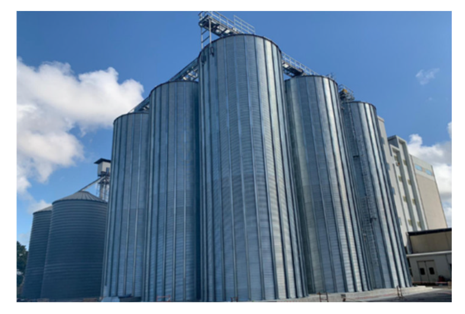
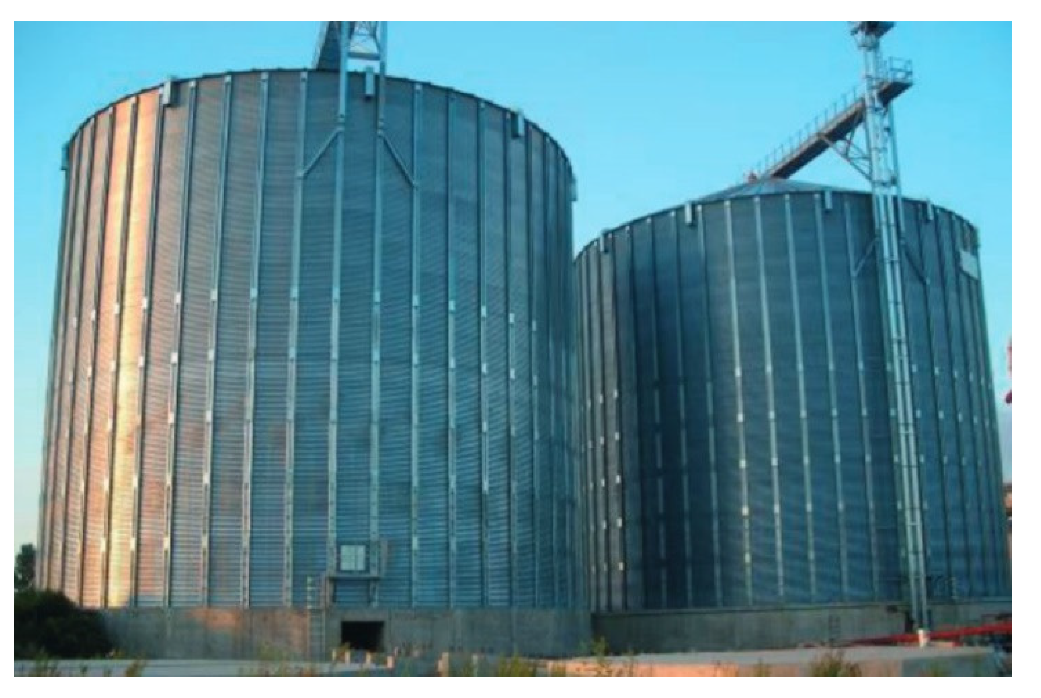
2. Structural Typology and Arrangement of Circular Silos

2.1. Construction Material and Geometry

Regarding to the construction material, as any other structures and infrastructures, silos are usually built by means RC, steel, stainless-steel, aluminum. In some cases, composite material can be used for some shell structures, as for special industrial applications or for the aerospace field [32]. Historically, silos were constructed using wood, brick, or stone as farm silos. However, steel and RC are the most spread as nowadays construction materials for silos in the different sectors. Whereas metal silos are characterized as thin-walled structures, RC ones have relatively thicker walls. Therefore, the first ones are more sensitive to compressive stresses and buckling, while the second ones are more sensitive to horizontal pressure. For that reason, RC silos are always preferable for tall and slender silos, where the axial compression forces are the governing stresses but not the circumferential ones [33]. However, this is not applicable to squat silos, where the horizontal pressure and the circumferential stresses are dominant, but not the vertical compression, thus steel is preferable.
Silos shapes are objects of classification, according to the purpose and the usage of the container. The circular plane shape is the most common feature among the majority of silos in industry [1]; however, the in-plan shape variation could occur in the supporting system under the silo. Thus, two main configurations are recognized: (i) ground supported silos [34], where the shell body rests directly on the foundation as anchored or unanchored to the ground; (ii) elevated silos [35], where the supporting system could be a structural frame or made by isolated columns (e.g., district supported silos) [7]. In both configurations, an adequate clearance under the discharge gate of a silo is required to allow for easy placement of a discharge conveyor, or other device [36]. Considering that, for the second configuration, a large space is required to allow for a possible transportation means beneath the elevated silo. However, for any of these typologies, the structural behavior of the shell body varies under different circumstances and different applied loads [1].

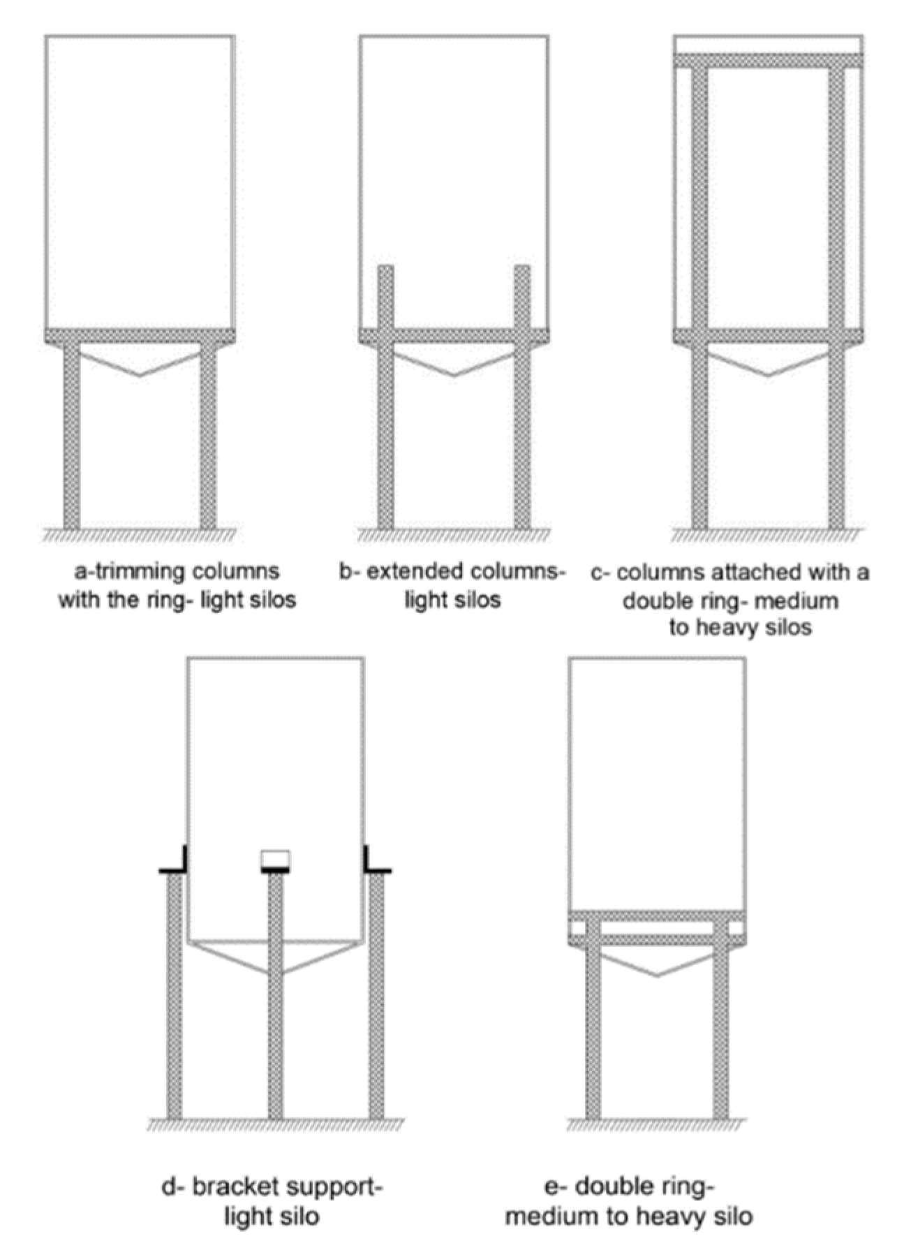
2.2. Supporting Arrangements

Silos vary in the supporting system depending on the capacity, usage, and operation. Hence, a significant variation in the structural behavior and the response to different excitations (e.g., seismic loads) occurs as a function of the supporting arrangement. Assuming that ground supported silos rest directly on the foundations, different support arrangements could be recognized for elevated silos (for instance, see Figure 3) depending on the silo size and on the magnitude of the force introduced into the shell body by the local support. Light silos could be discretely supported by columns, where a limited number of equidistant isolated columns are used with [37] or without [38,39] transition ring girder around the circumference. In addition, different means are developed to arrange the column-shell attachment, so that the resistance of the shell body to the local buckling and local failure is increased.
Talking about the discretely supported silos, the main deficiency is that the structure suffers high local axis compressive stresses concentration, thus possible local failures can occur such as plastic yielding or elastic buckling. Concerning this topic, Jansseune et al. [38] introduced a study in which a possible solution is suggested to increase the failure load of silos for this configuration. It consisted in adding longitudinal stiffeners as localized above each support resulting in a positive significant influence on the buckling behavior/loads. Nevertheless, it proves to be disadvantageous from a certain critical height over which the column is attached to the silo. The dependency of the buckling behavior and the failure load on the thickness and radial width of the stiffeners was investigated in [40]. Small silos with discrete supports could also be supported on local brackets attached to the side of the shell (for instance, see Figure 3). Later, Doerich and Rotter [41] presented a study outlining the behavior of discretely supported silos on several brackets rigidly connected to stiff columns. This study observed the local pre-buckling deformations and bifurcation mode and the local plastic collapse.
Another aspect that gains more interest among researchers is the ring girder, since it has a major role in reducing the potential buckling. The ring girder beneath the silo is responsible for redistributing reactions forces from supports into a more uniform stress state in the cylindrical shell body [37]. This aspect is dependent on the relative stiffness between columns and shell. In addition to that, the silo ring girder has a main role in carrying the circumferential force and to resist the radial component of the inclined tension in the hopper [42].
In discretely supported structures, a nonuniform axial compressive stress is developed in the shell wall. The uniformity degree of the stresses could be assessed by the criterion developed by Topkaya and Rotter [9] based on the relative stiffness of the ring beam and the cylindrical shell. Topkaya and Zeybek [10] presented a study aimed to assess the applicability of this criterion to cylindrical shells, accounting for global shear and bending. Combinations of different ring beam and cylindrical shell under global shear and bending actions were numerically analyzed, where the non-uniformity in the axial stresses was quantified. In conclusion, the result confirmed the applicability of using this criterion for the mentioned load conditions. The ratio between shell and beam stiffness was also addressed by Zeybek et al. [43], where a closed section ring beam with less stiffness than the ideal one was investigated. Still, the effect of the stiffness ratio on the ring beam stresses and on the buckling capacity of the shell was observed. The resultants’ stresses were recorded using a finite element (FE) parametric study and the analytic solution of Vlasov’s curved beam theory [44]. The paper concluded that the design of a ring beam based on Vlasov’s theory equation is conservative, since it ignores the contributions made by the attached shell and hopper. Moreover, the resulted stress reduction, compared to the values of the Vlasov’s theory, could be attributed to the stress redistribution being partly achieved by the shell, while this redistribution is determined by the shell-ring stiffness ratio. The shell buckling capacity suffers from significant reduction when the shell-ring stiffness ratio, ψ, exceeds the value of 0.1, and this becomes dramatic when ψ exceeds 1.0 [43]. With this regard, Zeybek and Seçer [37] provided design expressions for a ring beam of elevated steel silos and the effect of its relative stiffness (shell/ring stiffness ratio) on the ring behavior considering different supporting systems. These parameters were varied by in turn considering four columns, four columns with secondary beams, and eight columns beneath the silo, with the aim to develop design guidelines for the support conditions [37].

2.3. Imperfections’ Effects and Modelling

In typical cases, steel silos design concerns about avoiding stability failures, as occurs in many different shell structures, whether in the form of local or global buckling failure. However, the buckling capacity is very sensitive to the geometric imperfections as a function of amplitude and form. Geometric imperfections can be defined as the shape deviations from the perfect structure due to the manufacturing process. Hence, in the design of silos, a local high pressure must be imposed on the wall, for accounting the existence of geometrical imperfections.
In spite of the extensive experimental and theoretical works in the literature addressing the behavior of the axially compressed cylinders [14,45,46], there is still a gap between the predictions obtained by the numerical models and the realistic results provided by the experiments. However, the usual scatter among numerical and experimental predictions, in terms of buckling capacity, could be chiefly traced back to the structural imperfections that are unavoidable in the practical construction [47]. In addition, it is worth considering that this discrepancy is much severe when combining other imperfection types, such as loading imperfections [48,49]. This issue is considered as one of the main classical problems about homogeneous isotropic structural mechanics, which has not been fully understood [50]. The classical formulation for estimating the buckling load of cylindrical shell was derived more than hundred years ago, without considering any kind of imperfection [51]:
N p r e = 2   ·   π   ·   E   ·   t 2 3 ( 1 ϑ 2 )
where Npre is the buckling load of actual perfect cylindrical shells, E is the elastic modulus of the construction material, t is the wall thickness, and ϑ is Poisson’s ratio of the construction material. However, it has been long stated that the reduction of the geometrical imperfections decreases the discrepancies between the experimental results and the analytical [52,53] or numerical estimates [54]. Still, these differences are greater and greater in the case in which the axial compression is more significant than either pressure or torsion [52]. Nevertheless, there are no closed-form solutions to account for imperfection during the design phases [32].
Typically, in the design practice of thin-walled shell structures, the influence of the geometric imperfections could be considered by employing techniques known as artificial substitute imperfections (ASI) [55]. For example, eigen-mode imperfection technique could be adopted where the imperfection is assumed in the form of the bifurcation buckling mode taking into account varying imperfection amplitudes. Thus, the buckling strength could vary depending on the considered buckling mode and amplitude [54,56]. Eigen-mode imperfection is adopted in preliminary design of cylindrical shell structures; however, it could lead to a very conservative design and it is not easy to define the order and the magnitude of the rational eigen-mode shape imperfections [57]. Techniques of ASI are developed in the literature based on probabilistic methods to represent the geometric imperfection in cylinders. For instance, Monte Carlo simulation and first-order second-moments method were developed by Elishakoff et al. [58], aiming to determine the stochastic distribution of the buckling load. However, imperfection representation based on probabilistic methods are rather complex [59]. In the same context, Kriegesmann et al. [60] developed a probabilistic design procedure for cylindrical shells with a reduced computational cost comparing to the conventional ones. Away from probabilistic methods, different perturbation methods were introduced as deterministic approaches, such as the Single Perturbation Load Approach (SPLA) firstly proposed by Hühne et al. [61] and dealing with thin-walled cylindrical composite shells. Inspired by SPLA, single perturbation displacement approach, and single boundary perturbation approach were later developed [59]. Particularly, according to SPLA, the geometrical imperfection effect in a cylindrical shell could be included by introducing a radial perturbation load into the middle part of the cylinder. However, it was proved that using SPLA in the analyses of cylindrical shells provides realistic buckling characteristics [32]. SPLA has been used in many studies for different kinds of cylindrical shells as isotropic metallic [62] or composite [32,63]. Unlike probabilistic approaches, SPLA is independent from the need of measured imperfections, however, some limitations are noticed, as it does not cover all types of imperfections, as the boundary condition imperfection. Therefore, comparing the numerical results with the test buckling loads, the SPLA method can be not enough conservative, as shown in [63]. Using this geometrical imperfection approach for isotropic metallic shells, the obtained results provide superior design loads if compared with the standard of NASA SP-8007 [64], especially for those shells showing an axisymmetric buckling pattern in the pre-buckling range under axial loads [59].
Multiple Perturbation Load Approach (MPLA) was introduced by Arbelo et al. [65] as an extension of the SPLA for composite cylindrical shell. According to this approach, multiple perturbation loads are considered instead of the single perturbation load. Thus, three parameters were accounted for: the location, the number, and the magnitude of the considered loads. Based on numerical and experimental approaches, Jiao et al. [62] stated that MPLA is a more rational design method, especially for metallic cylindrical shell structures, comparing to SPLA. As a matter of fact, the lower-bound of cylindrical shell is sensitive to the number of perturbation loads, especially when these loads are evenly distributed along the circumferential direction. Still, the smaller inhomogeneous degree of the perturbation loads magnitude, the more possibility to acquire a robust lower-bound buckling load.
Steel silos are constructed conventionally by rolling separated steel panels and by welding them to form the silo walls, thus, unique imperfection types develop in the silo walls as consequences of the construction process. For instance, Pircher and Bridge [66] presented a study in which the imperfections caused by the weld-induced residual stresses in circular cylindrical silos was investigated. The study found that the weld material properties contributed to the changes in buckling and post-buckling behavior of the investigated cylinders. Moreover, the study considered the weld-induced residual stresses and found that these latter contribute to an earlier onset of yielding. Another study proposed by Ding et al. [11] indicated that the geometric imperfections in silos are closely associated with the joints of steel panels forming the wall. Using a numerical approach, Jansseune et al. [7] presented a study investigating the impact of different imperfection forms on the failure behavior of locally supported steel silos, considering different arrangements of stiffening/supporting and different equivalent imperfections shapes, e.g., nonlinear buckling mode, linear bifurcation mode, several post-buckling deformed shapes of the perfect shell, a weld-induced imperfection accounting for varying amplitudes and orientations. The study ranked the relevant imperfection shapes according to their adverse effects on structural behavior and response in terms of nonlinear buckling modes and post-buckling deformed shapes. It is worth noting that circumferential weld depression (also named type A) is a realistic imperfection as it is closely related to the fabrication process of silos. However, it is relatively considered the most deleterious compared to other imperfection forms according to this study. The study concluded that the inward imperfections are more unfavorable than the outward ones [7].
Nevertheless, optimization techniques, such as the one proposed by Ning and Pellegrino [49], could be applied to the structural form of cylindrical shell for minimizing the discrepancy between the geometrically perfect structure and geometrically imperfect structures, i.e., producing imperfection-insensitive axially loaded cylindrical shells. The technique mainly relies on achieving a reduction of the local radius curvature by changing the cross-section of the shell, to have an optimized wavy or sinusoidally corrugated wall based on numerical and experimental investigation [17,49]. The optimized cross-section provides a shell with a low sensitivity to geometrical imperfections, and high critical buckling stress than those of conventional circular cylindrical shell. Eventually, the shell failed with highly localized buckling modes leading to a superior mass efficiency more than almost all previously reported stiffened shells [49].

2.4. Buckling Types and Analysis

Like most of the conventional steel structures, buckling under vertical compressive stresses is the critical consideration for the thin-walled steel silos prone to a loss of stability [15,67]. The main sources of the vertical compressive forces in silos are the frictional traction pressure imposed by the stored material and the horizontal pressure. While the horizontal pressure imposed by the initial filling slightly increases with stored material depth, the frictional traction pressure significantly increases as the depth of the stored material increase, as shown in Figure 4 and according to the Janssen’s theory [33]. For this reason, the tall (or slender) silos are built with RC material, where the vertical traction pressure dominates the horizontal one. Instead, steel shells are susceptible to vertical pressure, thus, the shortest (or squat) silos are usually built with steel, especially where the horizontal pressure is dominant with regard to the vertical traction pressure.
Historically, extensive knowledge has been developed on the buckling behavior of an empty cylindrical shell under uniform compression even in combination with internal pressure. Different aspects of buckling and post buckling behavior of shell structures under uniform and well-quantified loads were historically addressed by several researchers, as defined in [68] and references therein. In [69], Teng extensively presented the research work performed on shell buckling through the last century. Nevertheless, the buckling strength of silos is dependent on many factors, such as the magnitude and distribution of both the frictional and horizontal pressures, the imperfections amplitude and shape, and the elastic restraint of the stored material against buckling. For instance, the eccentric filling or discharge causes variation in the applied pressure resulting in a worse stress state in the bin wall than even higher uniform pressure [70]. Therefore, some studies were introduced in the literature addressing the buckling behavior of silos under eccentric discharge. One of the earliest comprehensive studies was conducted by Rotter [15], in which experiments were performed to investigate the buckling behavior of a cylindrical shell under pressure directly induced by the stored solids. This study took into consideration buckling strength increment derived from the stored solid stiffness. The study treated flat-bottom silos, considering concentric/eccentric filling and discharge. For concentrically filled silos, according to the results of the experiments, a benign buckle of mostly axisymmetric mode was observed with significant reserves of post-buckling strength compared to the empty pressurized cylinders. For silos under concentric discharge, an accentuated buckling mode was observed. However, larger and different buckling modes were observed under eccentric discharging with a catastrophic collapse. In addition, two main remarks were also recorded as outcomes of this study: the first one is related to the filling depth, where it was found that the critical filling depth under discharges is as low as that one when the silo under filling loads only; the second one is relevant to the channel of flowing, where it was found that it was not critical to the buckling strength [15]. Similar issues were studied by Rotter [50], which presented buckling features outlining of thin shells under axial loads. The study addressed moderately slender perfect silos. Within this study, the author tried to come up with practical design recommendations. In this context, the study concluded that the behavior of these shells has many complexities, and to derive design rules out of the observed buckling features is far from being complete. Moreover, the author stated that the effect of unsymmetrical axial distribution among the cylindrical is the most critical point to understand. On this topic, the European standard EN 1991-4 [71] suggests a unique approach (mentioned in Section 5.5) to characterize the unsymmetric pressure exerted by eccentricities in silo filling/discharging. Sadowski and Rotter [67] introduced a study addressing the buckling behavior and imperfection sensitivity of a moderately slender silo, considering the real-life conditions and more realistic situations by taking into consideration the eccentric solids flow and the associated unsymmetrical pressure on the silo wall. The study adopted the approach suggested by the European Standard EN 1991-4 [71] to characterize the unsymmetric pressure exerted by the eccentric discharge. The study defined the critical regions of the highest compressive axial membrane stresses, where the silo may buckle, providing a dissertation on the phenomenon of the mid-height buckling failure that was frequently observed in the practice. In this phenomenon, a very high membrane stress developed in the thin wall coinciding with the lower bulk-induced internal pressures in the flow channel leads to eliminate the elastic restraint provided by the solids. The study mainly stated that a silo designed for symmetrical filling/discharging conditions only (according to EN 1991-4 [71]) may encounter a disastrous failure if eccentric discharging develops. In addition, this work was resumed by Sadowski and Rotter [16] for very slender silos, taking into consideration the imperfection sensitivity of the buckling failure mode. Similarly, this study characterized the unsymmetric pressure induced by the eccentric discharge in accordance with the description provided by EN 1991-4 [71]. Then, the geometric and material nonlinearities were considered for buckling calculations according to the European standards EN 1993-1-6 [72]. Authors concluded that the approach of EN 1991-4 [71]. For unsymmetrical pressure modelling (induced by eccentric discharge) is highly damaging for a very slender stepped-wall metal silo if it is designed only for symmetric pressure. The nonlinear FE model yielded that the European provisions EN 1993-1-6 [72] should be re-edited as they are formulated, considering experiments under axisymmetric conditions only.
However, the vulnerability of cylindrical shells to the different buckling modes could be reduced and the structural efficiency could be enhanced by adopting alternative structural arrangements, such as a closely stiffened shell, a cylindrical shell reinforced by stringers/corrugations [73] and rings [18], or even fiber reinforced polymers [19]. In other words, the basic idea is to use a higher efficient material in silos construction. In practice, the shell body of the silo could be combined with ring or vertical stiffeners, aiming to reduce the thickness of the shell without decreasing the buckling resistance of the silo. Corrugated walls could also be used in combination with different stiffeners, as for example, shown in Figure 5. One of the first studies addressing the stiffened shell buckling behavior were conducted by Flügge [74], pursuing to produce lightweight structures, in order to meet the demand of the aerospace and ship industry. A few decades later, Singer [75] developed an extensive experimental program and provided a remarkable approach (used until today) to simply analyze stiffened shells. In the recent scientific literature, a huge research work is introduced addressing meanly the stiffened shells used for aerospace applications, for example [76,77].
In the last few years, several researchers reactivated the research about stiffened shells used in the field of civil engineering. Some research directions approached the interaction of different strengthening techniques with corrugated shells. For instance, Błażejewski and Marcinowski [73] introduced a study in which they investigated the buckling behavior of vertical stiffeners attached to the shell body of a corrugated silo. The considered stiffeners have the characteristics of cold-formed steel sections. The paper deals with numerical modelling of the elasto-plastic collapse of the columns and it was revealed that the buckling resistances obtained by the proposed numerical approach were greater than their counterparts yielded by the European standard, appearing to be more realistic. In the same context, Rejowski and Iwicki [78] presented a study devoted to assess the stability of steel cold formed silo stiffeners, through a FE analysis. In this study, different modelling approaches were considered along with the symmetric and axisymmetric loads imposed by the stored material, according to EN 1991-4 [71]. The numerical calculations addressed a real cylindrical silo of corrugated sheets, with a 17.62 m height, 8.02 m diameter, and was strengthen by 18 vertical stiffeners of open thin-walled load-bearing profiles. The stability FE studies showed that the methods provided by EN 1993-1-6 [72] could be conservative, especially when considering the stiffener as a beam resting on elastic foundation, while the orthotropic shell theory is more realistic when compared to the FE outcomes. Thus, authors suggested a modification on the column elastic foundation stiffness resulting in comparable outcomes to the obtained FE solutions. The same authors proposed a method for the buckling strength estimate for stiffened corrugated silo with different geometry and including a simplified model.
Figure 5. Silo corrugated walls in combination with the vertical stiffeners (well-known as silo columns). Source: [79].
Applsci 12 03006 g005
Another way to increase the mass efficiency of thin-walled shells is represented by ring stiffeners. Jäger-Cañás and Pasternak [18] proposed a design procedure to bridge the gap in the standards related to quantifying the beneficial effect of ring stiffeners attached to the shell body under axial compression. The study investigated the applicability of the available design procedures for structures with significate radius/thickness ratio up to 10,000 (this ratio is limited to 5000 in EN 1993-1-6 [72]). The study revealed that high slender stiffened cylinders showed about 380% strength gains as benefit from the ring-stiffening, if compared to the unstiffened case. Recently, a numerical study calibrated with experimental series presented by Li et al. [80]. The study employed the 3D scanning technology to measure imperfection, and the FE analysis yielded very close result to the ones of experiments. The research evaluated the influence of different factors (ring-stiffener parameters, imperfection amplitude, ring geometry) on the buckling load of cylindrical shell.
Authors concluded mainly that the buckling capacity of ring-stiffened shells decreases significantly until the stiffener spacing is greater than two buckling half-wavelengths. A conclusive summary of the topics about structural typology and arrangement of circular silos is reported in Table 1.

3. Earthquake Loading and Seismic Response of Silos

Accounting for seismic excitations, as one of the main hazardous actions on structures and infrastructures, the response of silos has long been the subject of intensive research studies [4]. A considerable research work has been undertaken through the last century, addressing fluids-filled tanks to quantify the wall loads induced by seismic excitation where the sloshing action is a governing factor [81]. However, what distinguishes silos from tanks is that the filling material is of solid nature. Consequently, only a specific portion of the seismic inertia load is transmitted to the walls thanks to the shear strength and the stiffens of stored bulk. Thus, the stored material properties have a significant effect on the silo seismic response. For instance, the wall–solids interaction and its effect on seismic response is a critical point to be mentioned [82]. In general, the imposed loads by seismic excitation on a circular cylindrical silo walls are significant and could cause unsymmetrical pressures distributions on the silo walls. The main parameters governing the seismic response of the system are: (i) the height-to-radius ratio [83]; (ii) the physical properties of the contained material [82].; (iii) the characteristics of the ground motions [20]; (iv) the effects of the wall flexibility [5]. Several studies in the scientific literature were introduced to increase the knowledge about the response of cylindrical silos storing granular material to earthquakes [84]. In this context, shaking-table/vibration tests [85,86] were carried out in many cases, aiming to characterize the response of the system and observe the relevant parameters, such as the dynamic wall pressure, base shear, base moment in the wall, and the stresses exerted on the silo’s foundation.
Going into detail, Younan and Veletsos [20] analytically examined a vertical, rigid, and circular cylindrical tank storing homogeneous and linear viscoelastic solid under a harmonic earthquake-induced ground motion. The purpose of the study is to introduce a simple and reliable method of analysis for this kind of system. An analytical formulation was developed to describe the seismic response of the filled silo, which was adopted by the European standards EN 1998-4 [87]. In particular, the seismic response of the system can be analyzed by quantifying the contributing mass to the base shear, which was demonstrated to be governed by the slenderness ratio [20] and by the wall flexibility (relative to that of the stored material) [5]. Based on a FE model, Rotter and Hull [4] derived design criteria for steel squat ground-supported silos, accounting for earthquake response under quasi-static horizontal body force (uniform horizontal acceleration). In this study, the stored material was characterized by its elastic modulus as an isotropic and homogeneous material. The results obtained in this study were implemented in EN 1998-4 [87]. In this regard, aiming to verify load assumptions recommended by EN 1998-4 [87], Holler and Meskouris [86] characterized the behavior of seismically excited granular material steel silos. The study considered the variation of some key parameters, such as aspect ratios, the influence of the nonlinearity of the granular material, the wall—solids interaction effect, and the soil—structure-interaction influence. The results of this study suggested to reduce the effective mass considered in the analysis to achieve more economic and realistic design than the ones provided by EN 1998-4 [87]. Specifically, the proposed loads are conservative in the case of squat silos, while they are adequate for slender silos. Similarly, Yakhchalian and Nateghi [88] presented further numerical investigation addressing the seismic behavior of flat bottom ground-supported steel silos. The study emphasized the influence of the aspect ratio on the seismic response and concluded that assuming a constant value of acceleration distribution along the height of squat silos (based on EN 1998-4) leads to conservative design pressures for a squat silo, while this assumption is not conservative for a slender silo. Nateghi and Yakhchalian [89] further investigated the effect of granular material-structure interaction under earthquakes for RC silos. This study takes into consideration of different sources of nonlinearity in silo walls and in granular material. As the main result, it was observed that shear cracks developed when the interaction is neglected in the model. Silvestri et al. [21] evaluated, with an analytical approach, the exerted actions provided by grains on walls in circular flat-bottom silos during earthquake, leading to a new physically-based evaluation of the effective mass of grain. The study excluded the wavy wall silos. In particular, this study was devoted to the evaluation effective mass that acts on the silo walls during the earthquake. It turns out that this mass could be far less than the value proposed by EN 1998-4 [87] (80% of the total mass). Consequently, lower horizontal actions than the one provided by EN 1998-4 [87] can be adopted (especially for squat silos) and this result is also in accordance with the outcomes of the study presented by Holler and Meskouris [86]. For example, for a low height/diameter ratio (less than 1), the effective mass can be assumed in a range from 30 to 70% of the total mass of the silo, with a variation depending on the friction coefficient developed between silo wall and filling material [21]. Nevertheless, some theoretical limits were founded [90]. Refinements of the theoretical framework of Silvestri’s approach [21] were introduced by Pieraccini et al. [90], which provided a new set of analytical formulas for estimating wall pressures, wall shear, and bending moment. A series of shaking table tests on scaled silos was performed by Silvestri et al. [85], offering an experimental verification of EN 1998-4 [87] provisions and the analytical approach introduced in [21]. The experimental campaign (on a silo-sample made of polycarbonate sheets) revealed the strong effect of the wall-grain friction coefficient on the base overturning moment. This fact is consistent with the analytical approach in [21], whereas this effect is disregarded by EN 1998-4 [87]. Moreover, the results of this study stated that the base overturning moment is conservatively estimated by EN 1998-4 [87]. It also suggested that the horizontal acceleration is not linear in the vertical profile under earthquake input, although it is almost constant under low-frequency sinusoidal input. Later, based on these findings, Pieraccini et al. [91] presented an analytical formulation aiming to predict the natural periods of grain silos. A study presented by Durmuş and Livaoglu [92] the effect of soil structure interaction (SSI) on the dynamic behavior of silo system containing bulk material under seismic activity. The study concluded that the SSI could be ignored in practice, especially for squat silos since there are no considerable effects. Recently, Butenweg et al. [93] presented a study comparing applicable analysis approaches for seismic load calculations of grain-filled cylindrical steel silos. The results provided by static equivalent load approach and nonlinear time history analysis were compared. Both grain behavior nonlinearity and grain–wall interaction nonlinearity were considered for nonlinear time history analysis, as well as the SSI. Authors concluded that using a simplified linear acceleration profile along the height provides conservative results. Alternatively, it is suggested to use multimodal analysis on a simplified beam model to determine more realistic acceleration profile. In addition, the study affirmed that the approach of static equivalent loads does not accurately consider the fact that stresses vanish through the bulk material, especially in squat silos. Mehretehran and Maleki [83] investigated the effects of different aspect ratios on the dynamic buckling behavior of steel silos subjected to horizontal base excitations. Incremental dynamic analysis was considered for this study considering ten different earthquake records. The main findings by this study suggested that, in presence of ground motions, slender silos are more vulnerable to buckling failure, while squat silos present a considerably higher resistance under same seismic conditions. Recently, the same authors extended their investigation about aspect ratio influence on the silo dynamic behavior [94], by considering stepped walls steel silos under seismic excitation. Considering horizontal and vertical components of ground motion accelerations, different buckling modes were found, depending on the aspect ratio. Particularly, local diagonal shear wrinkles were observed in the elastic range for squat and intermediate slender silos, while elephant’s foot buckling modes in the elasto-plastic range were observed at the base for slender ones. Regarding the vertical component of the seismic excitation, it was stated that for silos, this component has a quite marginal effect, and it could be ignored. Silvestri et al. [95] presented a study reporting a series of shaking table tests on a full-scale flat-bottom steel silo filled with wheat. The experimental study aimed to evaluate some parameters, such as the static pressure, the basic dynamic properties of the considered silo, and the dynamic overpressure. To this aim, the fundamental frequency of vibration, the dynamic amplification, and the dynamic overpressure were observed. On the level of static pressure, this study stated that, the horizontal static pressure distribution is qualitatively consistent with the theoretical expectations and, during the dynamic tests, a redistribution of static pressures occurs due to the compaction of the granular solids. On the other hand, regarding the dynamic response, this study revealed that the damping ratio increases with increasing acceleration, and consequently, the dynamic amplification factor decreases. However, the dynamic amplification factor generally increases along the silo wall height (up to values around 1.4 at the top surface for earthquake inputs with a close-to-resonance frequency content). The resonance frequency (around 11 Hz for the case at hand) depends to a certain extent on the acceleration and on the granular solid compaction. In addition, the study stated that the measured dynamic overpressures seemed to be different from the EN1998-4 [87] expectations with slightly larger values. However, the upper portion of the silos showed a qualitative consistency with Silvestri’s theory suggested in [21] (especially in terms of dynamic overpressure vs. height profile), but not in lower portion. Jian et al. [96] presented a series of shaking table tests on flat-bottom ground-supported steel silos with corrugated walls. The experimental program aimed to evaluate the dynamic response and energy dissipation capacity of the system considering three different aspect ratios and their different seismic records.
The results emphasized the fact that the energy dissipation capacity is much larger for the silos with full or half filling conditions (aspect ratio = 1, 0.5) compared to the empty condition (aspect ratio = 0). Furthermore, the study concluded that the acceleration vertical profile is a function of the aspect ratio, and the silo with full filling condition (aspect ratio = 1) had a smaller dynamic response than the one with half filling condition (aspect ratio = 0.5). Regarding to the elevated silos seismic behavior, it is worth mentioning that, in spite of the fact that the stored material behavior and solid–structure interaction have a significant importance for the seismic response of ground-supported silos (i.e., additional stresses develop in shell walls due to the response of ensiled materials [4,20]), this is not applicable for elevated silos where the main concern is the supporting system and its attachment to the shell body of the silo. In fact, the stored material behavior and solids–structure interaction can be ignored in the analysis of elevated silos. For instance, a simplified approach is usually adopted for numerical studies, by simulating the silo content through static pressures and lumped-distributed non-structural masses [35,97]. A conclusive summary of the topics about earthquake loading and seismic response of silos is provided in Table 2.

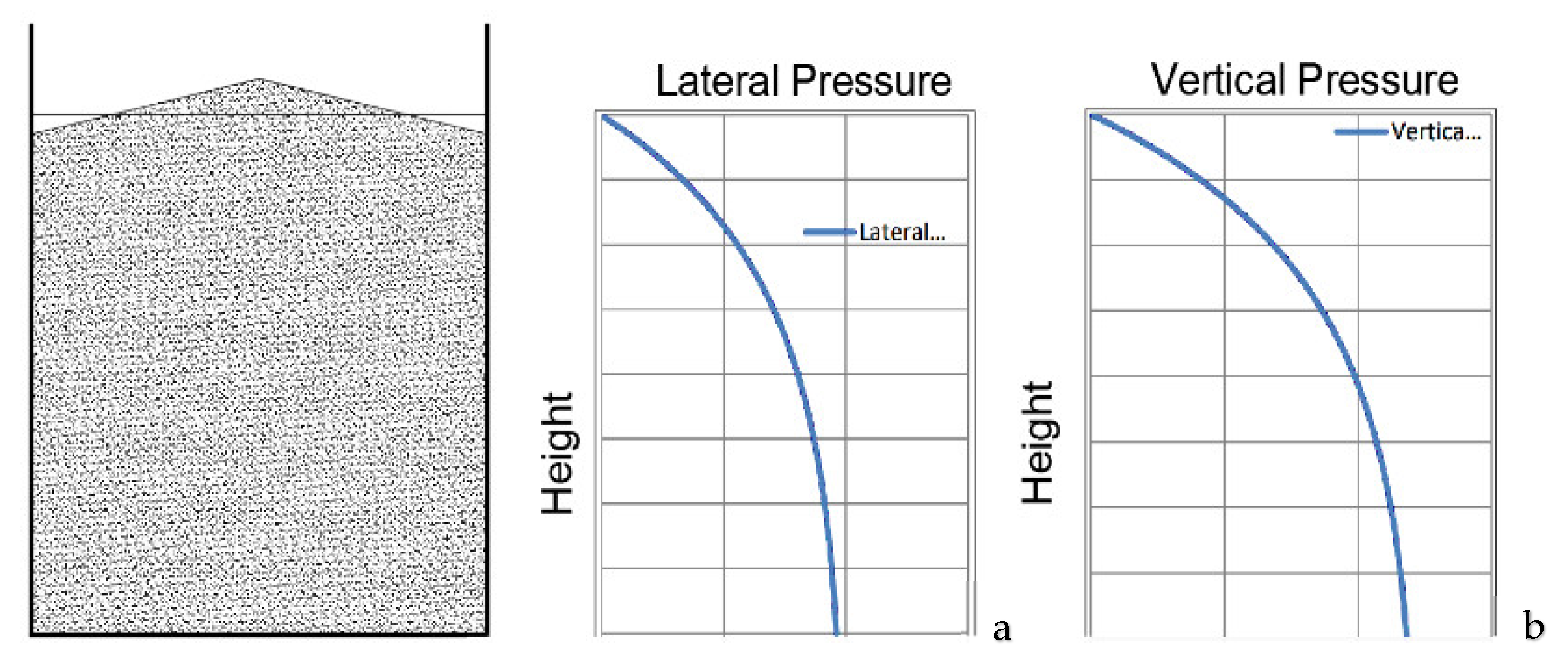
4. The Contained Material Properties, Behavior, and the Imposed Loads

After talking about the silos and their interactions with the external environment and the internal materials, the effective behavior of the material inside the silo is considered. As just mentioned in the Introduction, the main difference between silos and tanks is the contained material, which makes the difference in the loading conditions, grain–wall interaction condition, and the response to different excitations. While tanks are used to store liquids that exert only normal and symmetric pressure on the wall in the circumferential direction, silos are used for solid bulk materials exerting a normal pressure and interaction traction (symmetric or asymmetric) on the wall [1]. Different problems make the silos usage and design more problematic than tanks, which can be identified in the stored material anisotropy, material behavior asymmetry, and filling/flowing eccentricity. The stored material covers a large scope of free-flowing granular bulk with particle size ranging from micron size powders to lumps of 150 mm or larger. However, the contained material could be classified in multiple ways according to the relevant properties, as for example, largely treated in [98]. Thus, each silo is designed for a limited range of solids, where using the silo to store bulks out of the anticipated range could imply damages. On the level of practical design, the different international standards advise to determine the relevant material properties using either the provided tables or the experimental tests, as provided by the Australian standards (AS 3774-1996) [99]. Differently, the European (EN 1991-4) and the American standards (ACI 313-16) opt for the determination by test results [71,100]. Still, the commentary part of ACI 313-16 [100] using tables as guide for the only initial estimation.
Going into the available scientific literature, an experimental program was conducted by Moldena [101], aiming to examine the influence of particle properties and bedding structure (the filling method) on transmission of stresses in the layer of seeds (on the vertical/horizontal load exerted by the grain on the walls) considering rough and smooth wall surface. This experimental program indicated that the pressure ratio (identified as the ratio between lateral and vertical pressures) is strongly affected by the filling method and material type. Specifically, the results of this study reported that the circumferential filling provides advantages compared to the central filling.

4.1. Filling Material Properties

The typical filling solids in silos could be basically characterized by: (i) the bulk unit weight; (ii) internal friction angle; (iii) and grain-wall friction coefficient. Several factors, such as temperature, moisture content, composition, grading, have a strong influence on the properties of the stored material and shall be accounted for in the design and assessment of silo structures. For example, the moisture content of the stored material has a strong effect on the coefficient of wall friction and on the angle of internal friction, which is also distinctly affected by the bedding material that varies according to the filling method [102]. Thus, a wide variability on the pressure ratio exists due to the effect of the abovementioned parameters change. Eventually, this variability of material properties casts a shadow over the silo operations, and it could cause asymmetry of loads, flow disturbance, and frictional vibration [103]. Regarding this latter topic, intensive information can be found in [98].

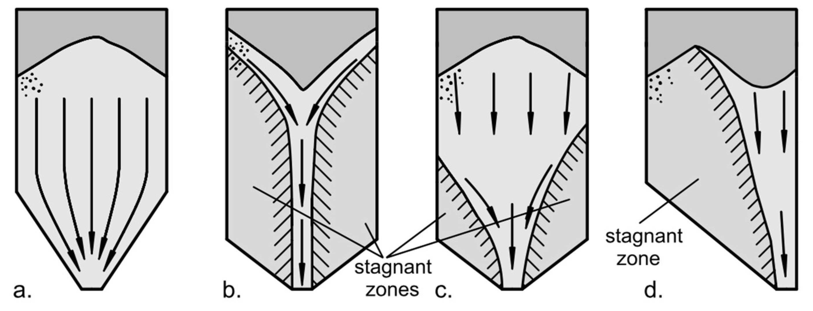
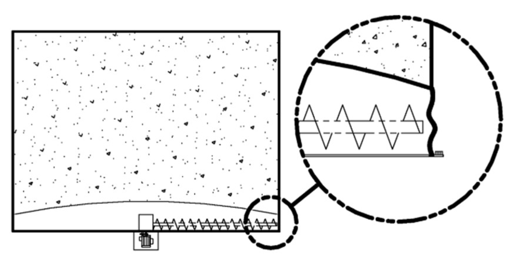
4.2. Discharging Patterns

Ideal silos must ensure a regular solid flowing compatible with the intended patterns specified by the design that avoid the discharging problematic phenomenon. Consequently, the desired flow rate and the intended operation of the silos are guaranteed. Depending on the grain–wall friction characteristics and the flatness of the hopper wall (silo bottom hopper) [71], two main flow patterns could be distinguished when bulk solids are discharged (gravity flow) from the bottom of the silo. The first main type of flow pattern is mass flow (as shown in Figure 6a) [71], where the whole mass of the material moves downward whenever the outlet is opened (given that arching does not happen). The second main type of flow pattern is represented by the funnel flow (also known as core flow or pipe flow), where the material flows from the top to the outlet through a funnel built by means of the material itself. In case of funnel flow, it is possible to develop stagnant zones (symmetric or asymmetric dead zones) in the upper silo part making pipe flow (as shown Figure 6b), or in the lower silo part making mixed flow (as shown in Figure 6c). Moreover, depending on the material properties, outlet position and number of mobilized outlets, eccentric pipe flow (as shown in Figure 6d) could develop as one of the funnel flow types, with eccentric channel forming near to the wall and exerting unsymmetrical pressure [67].
In the case of mass flow, the material at the center of the silo moves downward with the highest velocity, while the material near to the walls moves with the lowest velocity due to the friction or to the flatness of the hopper wall [102]. For overly frictional or extreme flat hopper walls, flow velocity of the material vanishes near to walls and the mass flow pattern converts to be funnel and this gives an interpretation on how the flow pattern could vary during the silo lifetime, depending on the material and grain-wall frictional interaction characteristics. When the discharge process is proceeding, there is an increase in pressure imposed on silo walls. This increase is considered by the different international standards, which vary in the complexity and the accuracy. For example, depending on the storage capacity, the geometry, the possible filling/discharging eccentricities, EN 1991-4 suggests different approaches to calculate the additional stresses exerted through discharging.
With this regard, Vidal et al. [34] presented a new dynamic model (employing Drucker-Prager plasticity model) for silo discharge simulation, considering mixed flow and mass flow silos. The study also investigated the variation impact of the wall friction and outlet radius. The outcomes of the study reported that the flat-bottom silos with mixed flow present overpressure values lower than the ones obtained in the case of hopper silos with mass flow pattern. Moreover, the overpressures mainly occurred in the lower part of the flat-bottom silo (14 m high and 2 m radius). The study also indicated that the discharge pressure increases as the size of the outlet increase and the grain–wall friction coefficient decreases.

5. International Standards and Solid-Induced Design Loads

This section aims to define the general prescriptions provided by the main international codes quantifying the loads imposed by the stored material on silo walls. Thus, defining the uncertainties, deficiencies, and possible development in this aspect. As imposed loads impact the structure geometry and its structural arrangement, determining the relevant loads is one of the critical points in the design and assessment of the silo structure. Hence, solid-induced loads are of large magnitude and they represent the dominant action on the silo, which has to be determined in a realistic way for having a reliable and robust design. Historically, three scientists developed three different widespread theories for calculating the lateral pressure imposed by the stored material on the silo walls: Janssen in 1895 [33], Airy in 1897 [104], and Reimbert in 1976 [105]. However, still until the present day, recent standards (e.g., EN 1991-4, ACI 313-97, and ANSI/ASAE S433.1 JAN2019) adopt Janssen’s approach. Focusing on the main international codes reported in this work, four directions can be followed, as reported below. Nevertheless, the first standard accounting for the topic of the loads calculation in silos was the German standard, published in 1964 and reissued in 1987 and 2005 (DIN 1055-6:2005 [106]), which was followed by several attempts to codify solid-induced pressure acting on silo walls. It has to be noted that the abovementioned standards vary in accuracy and complexity when dealing with solids-exerted load calculations. This variance is especially noted in terms of classification, discharging loads estimation, and eccentric representing. Section 5.5 briefly shows the most comprehensive approach among the ones of the abovementioned standards that is suggested by EN 1991-4. However, mutual deficiencies were noted between these standards. For example, loads imposed on internals (defined as inserts used to control the flow pattern and eliminate the discharge disturbance phenomenon [107]) are simply addressed by AS 3774-1996, while they are poorly considered by EN 1991-4, and never mentioned neither in ACI 313-16 nor in ANSI/ASAES433.1 JAN2019. Moreover, none of these standards deal with the imposed effect by these internals on silo walls, as well as solids-exerted loads in case of expanded flow developing.

5.1. EN 1991-4 (2006) “Eurocode 1: Actions on Structures—Part 4: Silos and Tanks”

Commonly called “Eurocode” [71], it is widely recognized as the world’s most advanced standard of its kind, as well as the most comprehensive silo design code currently in use [27]. Based on the reliability of the structural arrangement and the susceptibility to different failure modes, Eurocode’s provisions classify silos into three different action assessment classes (named action assessment class 1, action assessment class 2, and action assessment class 3), which help to determine the level and the sophistication of analysis. These classes take into account the storage capacity, the geometry, and the possible filling/discharging eccentricates. In addition, another classification based on the aspect ratio is considered by this standard. Thus, Eurocode proposes designs with essentially equal risk, in terms of load determination, which helps to provide logical treatment of different loads with varying complexity, e.g., the eccentric loads and discharge pressure. Therefore, this fact gives an advance over other international standards [108]. A noted insufficiency exists in covering some common load cases, such as the loads imposed by the grain swelling, expanded flow (combination of funnel and mass flow [102]), external equipment, and load variations due to inserting internals.

5.2. ACI 313-16 (2016) “Design Specification for Concrete Silos and Stacking Tubes for Storing Granular Materials and Commentary”

This standard [100] is directed to study the RC silos. Anyway, calculating methods of the loads exerted on silos should be independent from the construction material. This standard adopted Janssen’s theory [33] to calculate the static uniform filling pressure on walls. The discharge-induced pressure is computed by using a minimum value of the overpressure factor (Cd), assumed equal to 1.6. However, this is a rough estimation and it is relatively large if compared to the load magnifying factors (horizontal pressure discharge factor, Ch, and wall frictional traction discharge factor, Cw) recommended by EN 1991-4 [71] and determined based on equations after considering the action assessment classes of the silo. The old edition of this standard (ACI 313-97) ignored the calculation of non-uniform pressure exerted by asymmetric flow and did not endorse any method for evaluation of the effect of the asymmetric flow. The current edition (ACI 313-16) mentioned two methods to deal with pressure induced by the asymmetric flow. In other words, it takes into consideration several aspects, such as the industry’s experience of the professional design, the characteristic of flow pattern, the nature of the surfaces and the stored material, and suggests to use either flow channel method or eccentricity method. In this sense, Eurocode suggests different approaches to deal with the non-uniform pressure induced due to asymmetry, by considering patch loads or nonuniformly distributed pressure based on the silo classification, wall thickness, aspect ratio, and eccentricity.

5.3. AS 3774-1996 (1996) “Loads on Bulk Solids Containers”

The Australian standard [98] was first published in 1990 and revised in 1996 and it is considered the most compatible code with the European standard, even though it does not adopt the action assessment classification. However, it considers different systems of classification for containers depending on geometry, wall surface characteristics, means of flow promotion, pattern and geometry of the flow. Further classification systems for the bulk solid are considered on the base of the particle size. In addition to that, this standard recognizes four different load groups, which are subdivided into load types. The load groups are: group A (dead loads), group B (normal service loads), group C (environmental loads), and group D (accidental loads). However, some deficiencies exist in quantifying solids-exerted loads in case of mixed/expanded flow.

5.4. ANSI/ASAE S433.1 JAN2019 (2019) “Loads Exerted by Free-Flowing Grain on Bins”

This standard [109] was developed in 1988 by the American Society of Agricultural and Biological Engineers (ASABE) and it was approved for first time as American national standards in 1991. Later, the most recent version was revised and approved by the American National Standard Institute (ANSI) in 2019. The scope of this standard was limited to provide only centric filling/discharging loads (adopting Janssen’s theory [33]) and flowing methods to store agriculture whole grains. However, it does not provide any rules to cover the solid-exerted loads in case of mass flow, expanded flow pattern, and some hopper geometries (e.g., asymmetric cone/square pyramid and multiple hoppers joined together).

5.5. Loads Evaluation Philosophy According European Standards EN 1991-4:2006

Generally, three main factors must be considered to estimate the loads exerted on silo walls: the silo geometry, the stored material properties, and the discharge flow pattern. Since the pressure applied on the silo wall differs depending on the stored material situation (flowing or stationary) and on its flowing pattern, the assumption of a uniform distribution around the perimeter of the bin is one of the most common design errors causing failures [70]. As a matter of fact, an increment of the uniform pressure may be imposed to cover the discharging and unsymmetrical actions caused by eccentric filling/discharging [71]. Generally, the loads imposed by the stored material on silos could be classified as horizontal wall load, wall frictional pressure, patch loads, hopper loads, and kick loads. This section addresses solids-exerted loads on the silo walls. These loads could be symmetric or asymmetric, either distributed or patch loads and they are represented according to the different standards. For instance, according to EN 1991-4 and depending on the action assessment classes of the silo and its geometry, the loads imposed by the stored material on the vertical silo wall could be calculated. These loads are generally classified into two main categories: (a) filling loads; (b) discharge loads. The design may depend solely on the filling loads, only if the internal pipe flow is guaranteed. However, the filling loads are represented by a uniform symmetric pressure, which is a static pressure subdivided into horizontal and frictional traction induced by the stored material and affected by several factors, as the silo geometry, material properties, and the wall–material interaction coefficient. In addition to the symmetric filling pressures, filling patch loads, expressed in terms of localized horizontal loads, should be considered without an associated frictional traction. Patch loads are considered to account for unsymmetrical pressures caused by a possible eccentric pile of filling, especially in the case of small eccentricities. On the other side, unsymmetrical distribution of the horizontal pressure should be considered in case of large eccentricities. Similarly, discharge loads are represented by a uniform symmetric distributed pressure in combination with patch loads. The uniform discharge pressure can be considered by increasing the uniform filling pressure using discharge magnifying factors, in order to account for the increase in both the horizontal and frictional pressure. Discharging patch loads can be considered in a pattern of only normal pressure (no frictional traction) to account for the accidental asymmetry of loading during discharge in case of small eccentricities, while the unsymmetrical horizontal pressure on the wall should be accounted in case of large discharging eccentricities. Patch filling/discharging loads may be ignored for silos in action assessment class 1, while a uniform increasing in the symmetrical pressure may be used when considering special structural arrangements to substitute these loads in the action assessment class 2. When large eccentricities are expected, as large outlet eccentricity or large filling eccentricity with high slenderness, a special procedure must be followed to account for the unsymmetrical wall pressure distribution resulted by the eccentric pipe flow channel. In the end, the loads on the vertical walls could be expressed in terms of symmetrical loads, due to filling and discharge that include horizontal pressure and frictional traction. In addition, the unsymmetrical loads caused by filling/discharging eccentricities should be represented either by considering patch loads for small eccentricities, or by considering unsymmetrical pressure (horizontal pressure, defined as ph, and wall frictional traction, defined as pw) for larger eccentricities, depending on the action assessment class of the silo.

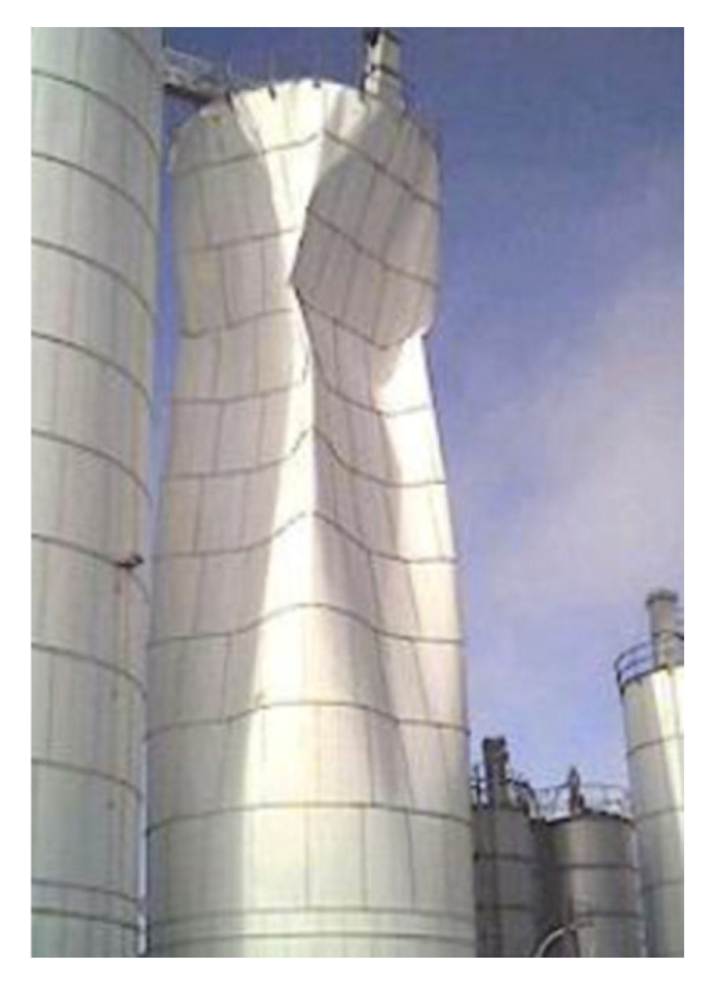
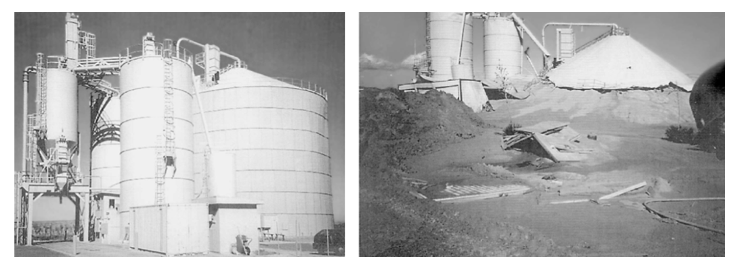
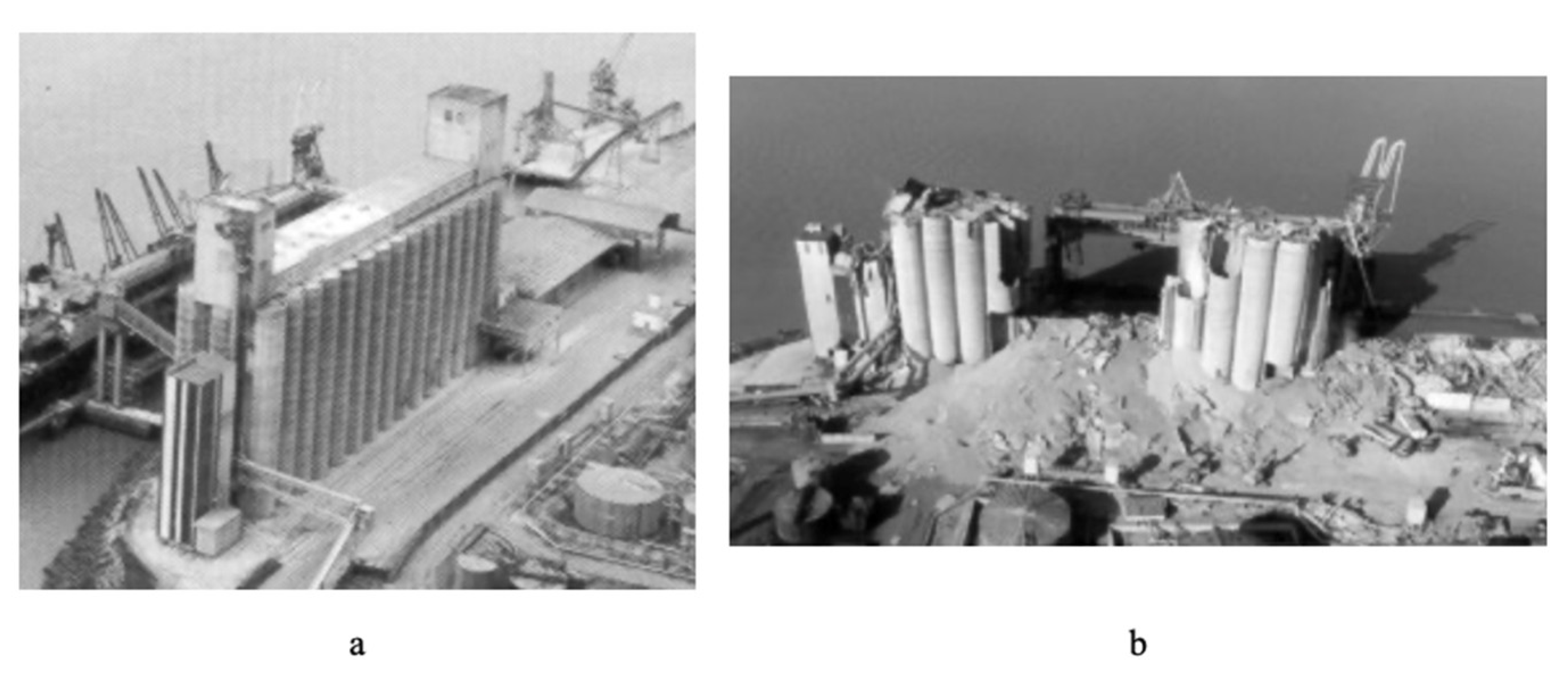
6. Failures in Silos: Main Causes and Modes

Depending on the function, location (e.g., industrial site), and usage of silos, unconventional conditions and loads could be imposed on the silo structure in combination with solids-exerted pressures. Thus, extensive stresses/deformations could develop in the walls. However, as thin-walled structures, steel silos have a susceptible structural configuration, storing massive content of the material that could touch thousands of tons [71]. Hence, unusual failure modes are frequently observed in the real life, leading eventually to a catastrophic collapse with considerable consequences, costs, and even loss of life. Moreover, silos could lose their functionalities due to discharge disturbance phenomena, such as arching [110], ratholing [102], silo quake [111], and segregation [112]. However, these phenomena are basically affected by different parameters, such as the solids properties/behavior, wall frictional characteristics, filling method and the discharge flow pattern. However, different failure modes and shapes could occur in silos depending on the capacity, geometry and the construction material, as it is reported in the literature [28,113,114]. For instance, elephant’s foot buckling (an outward bulge just above the base of the cylinder) is one of the main failure modes that can be noted in the steel cylindrical shells, as a result of combination of axial compressive stresses, circumferential tensile stresses, and high shear stresses [115]. In the following, several causes of silo damage are reported, accounting for several topics developed in the scientific literature, such as design errors, constructional errors, misuse errors, maintenance errors, up to define the collapses provided by soil damages, extreme events such as earthquakes, thermal ratcheting, and dust explosion phenomena. When talking about silos failures, the complete collapse is often achieved when an extensive deformation occurs, and, in most of the cases, the failure could be attributed to lack knowledge in the abovementioned aspects or in the combination of any of these categories that contribute to the collapse.
One of the most common design errors is the lack of knowledge on flow pattern in case of the discharging process, where the designer should be aware of the required flow pattern based on the functional requirement. The silo design should guarantee that the discharge process follows the assumed flow pattern [116]. Moreover, silo design should account to resist the imposed pressure through the intended discharge process, which varies according to a flow pattern. Furthermore, the actual flow pattern may oscillate between mass flow and funnel flow, as a function of several governing parameters including the moisture, particle size, and temperature of the stored material [117]. Therefore, any mis-assessment in any of these aspects could lead to deficiency in the usage and it may lead to failure [29] with devastating results. For example, the discharge pressure could be ignored when pipe flow—but not inclined pipe—is ensured by the geomatical design or by mechanical equipment [71], while unsymmetrical pressure should be considered when mass or mixed flow occurs with or without partial contact to the silo wall [71]. With this regard, Zaccari and Cudemo [29] reported the failure event of a steel silo containing thousands of tons of limestones used in thermal-power plant. The failure involved a very huge shell deformation of the wall which is constructed with a stepwise manner of thickness. The study attributed the failure to the miscalculation of the pressure distribution imposed by the eccentric solids flow [29] in the same regard, since the flow pattern is extremely influenced by the stored material properties, researchers, e.g., [116], and some standards, e.g., [71,100], stated that the material properties should be determined by testing representative samples of the material, instead of using some tables to determine the material properties that could be risky at best.
As just anticipated above, another cause of failure is given by the asymmetric disposition of the filling material (eccentric material withdrawal). In such a case, an eccentric flow channel can develop in silos, occurring in several situations such as the nonuniformity in outlets opening, or improper design of the feeder [116]. This phenomenon causes a severe non-uniform circumferential pressure [67], which is either overlooked by the designer or incorrectly accounted, and eventually it causes collapse or buckling at best, as shown in Figure 7. Therefore, more failures have occurred under the condition of asymmetric flow patterns than any other [16]. In this context, Kobyłka et al. [118] stated that non-symmetric pressure could be imposed on the silo wall due to inserts or asymmetric flow patterns. Moreover, an experimental study introduced by Hammadeh et al. [119] revealed that the change in the location of the inserts (particularly top cone with trunk cone bottom) has an important impact on the flow pattern and on the flow pressure. Practically, the study stated that improved flow shape is developed with a corresponding lesser flow dynamic pressure if inserts are positioned close to the transition section of the silo. However, the generated non-symmetric pressure could combine with the local pressure peak, causing structural deficiencies even for a slightly asymmetric flow pattern that could be ignored by the designer. In this regard, Horabik et al. [120] found that the load asymmetry resulting from off-center discharge could be reduced by the anisotropy of the mass of the grain, which could be achieved by imposing an off-center filling.
Moreover, another of the failure causes that could be avoided in the design stage is the changing of the storage condition. As the majority of the solids stored in silos in practice have a high dependency on different parameters, such as compaction, moisture content, and internal/atmosphere temperature fluctuations. For example, some bulk solids tend to expand with higher moisture content [121], leading to a possible increasing in the lateral pressure on the silo wall, thus increasing in the hoop stresses [116], which may be not accounted for in the design stage. However, this could be avoided by designing for a wider range of possible moisture content.
Silos could suffer from other kinds of errors, such as the constructional errors. Typical examples of constructional errors are the unauthorized design changes and poor-quality workmanship, as it regularly happens in other construction sites. Nevertheless, the effect of these errors could be eliminated by avoiding unauthorized changes in the design during the construction, following the work plan set by the designer and employing qualified contractors by ensuring close inspections of the construction process [116]. Still, despite a proper design and a precise construction work, silos could fail. The reason of this occurrence could be utilizing the silo for applications differs from the purposes for which it has been designed. In fact, silos are very sensitive to the material filling and the related properties [103]. Different logistic issues could be raised when the stored material presents a wide variation from the material considered in the design, such as the variation in the flow pattern, or the different load conditions. In addition, possible flow obstruction could be experienced such as arching. In case of arching phenomenon developing, the full weight of the silo content applies on the formed arch that transfers it, in turn, to the arch ends. Eventually, if high concentrated reaction forces are applied on the silo walls, this provokes potential local plastic failures, as for example shown in Figure 8 [116]. Furthermore, using the silo to store different materials could also result in self-induced silo vibration and dynamic loads [111]. However, at some point of the silo life, the changing of the usage purpose of the facility could be required and, to avoid any catastrophic consequences, a structural assessment should be implemented to check any possible deficiencies that would yield from these changes [116].
For ensuring long life span and safe operation of silos, it is necessary to provide regular maintenance. In this regard, it is necessary to observe the visible defects on silos, which are caused by the ordinary or overuse of the silo structure. Typical defects in steel silos could be local deformity, waviness, dents, thickness reduction, and distorted joints/bolt-holes, as mentioned in [116]. However, other common defects are typically observed for RC silos [114] (e.g., cracks, corrosion, exposed rebar, spalling concrete, and deterioration in RC walls). While ignoring the need for maintenance and overlooking the observed distortions could lead to potential collapse and structural deficiencies, improper maintenance can end with counterproductive effects. For example, changing the internal wall surface finishes by painting may lead to change in the frictional properties of the wall. Consequently, new frictional characteristics can diverge from the specifications set out in the design, resulting in a significant impact on the flow pattern and thus on the solids-exerted loads [122]. Obviously, cladding or internal lining material should be durable, and not react with stored substances inside the silo [36]. In this regard, the same effects are applied if the internal wall surface finishes change due to the corrosion (roughening) or abrasive wear (polishing or roughening) over time [71].
Furthermore, as like any other structures, silos could collapse due to failure of the soil. Considering that silos have a small floor area or diameter compared to the height (whether it is steel or concrete), large stresses can develop in the soil under it, mainly due to the massive weight of the bulk material. Generally, the silo’s foundation design is more critical if compared to other standard structures. In the typical case, uniform stresses (pressure bulb) develop in the soil under foundation and problems could occur when the pressure blub is distorted due to off-center filling/discharging [70] or when lateral loads like wind and earthquake occur [92]. When pressure blubs overlap under adjacent silos (e.g., cellular structure), the soil is overstressed, and the structure ends up with extreme settlements. A typical example of this effect is the well-known case of the Transcona Grain Elevator accident [123], Canada, where the plant was made by 65 bins covering several square miles. The silos battery was built a hundred years ago and it failed after only one month after the construction was completed, as it was loaded to 87.5% of its capacity within a month (quick loading) [123]. It was observed that foundation failures in clay occurred when the silo is quickly loaded for the first time [70]. Luckily, the foundation problems were solved, the grain elevator was righted, and it is still in use [124].
Another highly investigated cause of silos collapse is the exposure to extreme events, such as earthquakes. Seismic action can cause serious accidents as observed, for example, in Italy after the recent 2012 Emilia–Romagna earthquake event. As for buildings in [125], extreme events like earthquake can provide progressive collapses that in silos can occur also for static loads [126]. Focusing on earthquakes, in similarity with the buildings, damages to silos structures can be firstly observed and mapped [127], and after in the case of not total collapse, they can be adequate with proper retrofit techniques [128]. Additional topic of interest is the kind of hazardous event, which can cause different responses on the focused structure, on the base of some characterizing parameters (e.g., magnitude or ratio, see [129] for more information). In general, silos that experienced earthquakes suffer from additional stresses combined with the ones induced by the stored material, mechanical equipment, and different sources. Slender silos are more vulnerable to horizontal forces, as they could be subjected to overturning due to high seismic inertial forces, especially when the anchoring or the foundation fails. What makes this effect more problematic, is the massive weight of the stored material, which increases the weight of the entire structure. As is shown in Section 3, the effective seismic mass of the stored material is an active research zone, and it is still a matter of dispute among researchers. An accident was reported about the full-collapse of a slender silo among group of 4 steel silos after the seismic swarm occurred in the Emilia–Romagna, Northern Italy, in 2012. In addition, visible buckling damages in the highly stressed areas were observed on the other three silos of the group [93].
Many strategies were introduced by the literature regarding the seismic risk mitigation of elevated [35] and flat-bottom ground supported silos or tanks [130]. For instance, Basone et al. [130] presented a study in which the seismic vibration-induced damage of ground supported fuel storage tanks was investigated. However, similar strategies could be extended for silos storing solid materials. In this study, a new type of seismic isolation was adopted to mitigate the seismic risk, which was based on a finite locally resonant metamaterial concept. In this scope, four meta-foundations characterized by different layers and column heights were designed, exploiting properties of metamaterials, and combining them with classical seismic isolation concepts by using the traditional construction materials (e.g., steel, concrete, and wire ropes). The study was made in accordance with the Italian standards and considering the response spectrum for an active seismic site located in Sicily, Italy (peak ground acceleration, PGA, of 0.56 g for safe shutdown earthquakes and soil type B). Two tanks were evaluated by means of a performance index (PI), and an energy dissipation index (EDI). Time history analyses showed that base shear was reduced by 10–15% for slender tank with one-layer meta-foundation. Nevertheless, it was observed that the case of two-layer meta-foundations presents low efficiency for this tank typology. On the other hand, in case of board tanks, the base shear is reduced by up to 30% with one-layer meta-foundation and about 10–15% in case of two-layer meta-foundation. Moreover, the effectiveness of base isolation as passive control systems was presented by Paolacci et al. [131], where the effectiveness of different isolation techniques on floating-roof steel storage tanks was investigated through numerical and experimental models of shaking table tests (“La Casaccia” Research Centre—Rome, Italy). Particularly, two alternative base isolation systems have been used: high damping rubber bearings devices (HDRB) and PTFE-steel sliding isolation devices with c-shaped elasto-plastic dampers (SIEPD). The test was performed on a reduced scale (1:14) physical model of a real steel tank (diameter 55 m, height 15.6 m) typically used in petrochemical plants. The results affirmed the high efficiency of both the isolation systems and, at the same time, the reliability of lumped mass model for the prediction of the seismic response of isolated above-ground tanks. In the same context, a study presented by Kanyilmaz and Castiglioni [35] the efficiency of traditional base isolation techniques (curved surface slider) to reduce the seismic vulnerability of elevated steel silo group, taking a real case study located in Livorno (Italy) as a reference. A three-dimensional model was developed, by using the simplified approach proposed by Castiglioni et al. [97], where the silo content is simulated with static pressures and lumped-distributed masses. For the purpose of this study, a single curved surface slider was proposed (designed and optimized based on the horizontal stiffness and the friction parameters) and the seismic performance was compared after and before the retrofit interventions. Whereas the original system suffers from stress concentration, elastic deformation, and yielding in the supporting structure, it was noted that all the response parameters were positively reduced after retrofitting. The different observations proved the advantages of the suggested system in terms of inelastic deformation, global horizontal shear, inter-storey drift, isolator displacement, and residual displacement.
Another cause of failure of silos is given by the mechanical phenomenon known as thermal ratcheting. This effect could develop in the metal silos, since steel is more sensitive to the temperature fluctuation than the RC. In general, for a possible rise in internal/external temperatures, steel walls of the silo expand allowing the stored material to settle. However, when the temperatures drop, silo walls are subjected to a contract (or a shrink), which is in contrast with the settled particles that cannot move if a discharge phase is not taking place. Thus, the expansion becomes irreversible and thermal stresses accumulate, which in turn amplifies the tensile stresses in the wall. This phenomenon is repeated over many and many thermal cycles and, eventually, this ends up with a failure [70]. This phenomenon could occur due to any cyclic swelling and shrinking conditions (e.g., moisture fluctuating) applied to the stored material, as shown in [132]. One famous example of this kind of failure is reported when describing the collapse accident of a new brand steel silo containing thousands of tons of fly ash, shown in Figure 9, and located in southwestern United States [116]. The experts attributed the accident to the thermal ratcheting phenomenon, which was not considered in the design. Despite this, most of the main international standards account for the thermal ratcheting effect, especially the European, American, and Australian ones [71,99,109]. Regarding this topic, the scientific literature provides different detailed stress models to account for the phenomenon of thermal ratcheting, often opting for FE methods [6]. On the other hand, a discrete element method (DEM) along with experimental tests approaches was defined by Nahia et al. [133]. This study investigated the effect of this phenomenon on the shell walls of tanks used in thermal energy storage systems (as essential parts in power plants). The investigated silos typically contain a thermal storage medium of solid material (e.g., steel, sand, gravel, or rock). The functionality of this kind of silos makes it exposed to differential expansion between filling and walls. DEM was used to simulate the stored material and two different thermal approaches were considered. Specifically, homogenous heating and vertical gradient heating along the wall’s height were investigated as typical thermal configurations. The study revealed that higher stresses develop in silo walls in case of thermal gradient along the height. Moreover, the significant effect of slenderness ratio, the internal friction, and the solids–wall friction on thermal stresses was affirmed through the simulation of DEM. An increased radial stress was recorded and it was equal to three times the initial one after performing 108 cycles. In the same context, a statistical description of the pressure on the wall of silos storing hot material was introduced by Maj and Ubysz [134]. The study employed an experimental and statistical approach to quantify the total load given by the combination of thermal loads and static loads on the walls of RC silo.
Still, in the context of extreme events threaten silos, an explosive atmosphere could be created inside the silo depending on the nature of the stored substances. The risk of fires and explosions is presented inside the silo [135]. For example, airborne organic/metal dust generated during loading and discharging, or gas generated within the container, such as bulk-emitted flammable gases during the storage [36] or fermentation process (fodder) leading to methane generation. However, pressure loads exerted by industrial dust explosions are extremely complex to quantify and predicting their consequences by numerical models (depending on fundamental, physical, and chemical principles) in general is beyond reach [136]. Pineau et al. [137], introduced a study about an accident of grain silo explosion, as shown in Figure 10, at Blaye, France, occurred in 1997, causing 12 casualties. Particularly, the final report of the accident [138] suggested that the explosion could be attributed to the generation of flammable dust–air mixture inside the silo along with existence of ignition sources (sparks or mechanical heating effects, static electricity, electrical sparks, or the self-ignition of a deposit of dust).
However, the explosion risk in silos could be eliminated by following the preventive measures [36]: (a) avoid design for near horizontal internal surfaces where the dust may accumulate; (b) provide explosion relief vents or doors [139]; (c) select the proper electrical equipment to reduce the risk of dust explosion according to the relevant standard, e.g., EN 61241-17 [140]; (d) classify the hazardous areas in relation to combustible dusts according to the relevant standards, e.g., EN 50281-3 [141]; (e) locate the electrical equipment or the sparks sources away from the hazardous areas; (f) provide lighting protection as an ignition hazard. A conclusive summary of the topics about the main failures modes and causes of silos is provided in Table 3.

7. Assessment of Steel Silos Vulnerability

As the last part of this paper, it is essential to mention that despite of the fact that robust design methodologies can be improved to avoid the risks mentioned in Section 6, it is necessary to prevent losses by monitoring the conditions of existing silos, aiming to assess the behavior under the realistic circumstances. Consequently, a safe and continuous operation of these structures and the relevant facilities must be guaranteed. In fact, destructive (DTs) and non-destructive tests (NDTs) have been developed as tools to estimate the cylindrical shells efficiency, or as proof-testing of structure, or for the purpose of theoretical analysis validation. However, the common buckling tests have a destructive or terminal nature, as the loaded structure buckles with large plastic deformations. Thus, the same test cannot be repeated and definitely it is not suitable for silos in service. Therefore, the desire for NDTs has grown [30]. However, for more practical solution, several assessment techniques were developed as NDTs applicable for existing silo structures. Generally, non-destructive methods can be classified to be dynamic or static and they could be employed for either direct determination of the buckling load and determination of the actual boundary conditions leading to better numerical determination of the buckling load [30]. One of the first NDT to predict the buckling loads of steel structures is the Southwell approach, which was initially developed for a simple column [51].
Later, this approach was extended to include cylindrical shell [142], but the notable drawback of this approach is represented by the need of applying high loads, in order to come up with reliable prediction and this can threaten the non-destructive feature of the test [143]. However, one of the most common NDT is the vibration correlation technique (VCT) that is being employed currently to predict the buckling capacity of shell structures used for several applications. In the following, this technique and its applicability for silos is presented. For purpose of vulnerability assessment, the vibration correlation method can be used. This method can be defined as an NDT used to estimate the buckling load from the pre-buckling stage of the structure, based on the variation of the natural frequency with the applied loads. Historically, this approach was firstly derived for columns depending on the fact that the buckling modes and vibration modes are similar for a simple structure of a column. In other words, this method takes advantage from the similarity between the buckling behavior and the free vibration behavior of the relevant structures. The relationship between the squared frequency and the compressive load is nearly linear for columns with different boundary conditions [144], while it is exactly linear in the case of simple supports columns, where the vibration mode is identical to the buckling mode and it is presented analytically in [30] and reported below:
( ω n ω n 0 ) 2 = 1 ( P P n )
In the equation, ωn is the nth natural frequency of the loaded column, ωn0 is the nth natural frequency of the unloaded column, P is the applied load, and Pn is the Euler buckling load corresponding to nth vibration mode. Later, VCT was further developed to address plates [145] and shells [146]. The main feature of this method is the ability to estimate the destructive buckling behavior of relevant structure from a simple vibration test, where results are obtained by subjecting the addressed structure (e.g., cylindrical shell) to compressive loads without reaching the instability point. This technique was thus extended for plates by Lurie [144], which declared that VCT is reliable only when it is applied on specimens having small initial imperfections. This fact was also confirmed by Chailleux et al. [147], identifying a remarkable deviation from linearity in the case of plate structures with relatively significant initial imperfection. Some attempts to exploit the concept of VCTs for cylindrical shells were firstly proposed in 1970s [148], for the purpose of aerospace applications. In this application, VCT was used for determining the actual boundary conditions in numerical calculation of stringer-stiffened shells, as based on laboratory-type and on realistic boundary conditions [149]. Then, it was extended to the direct prediction of buckling, as just shown in [148]. Currently, several researchers attempt to further exploit VCT for the purpose of erected cylindrical shell assessment. For instance, Arbelo et al. [145] identified the range of applicability of the VCT for unstiffened cylindrical shells, showing the efficiency of the technique applied to these structures. In addition, the authors demonstrated the advantages given by the results of the FE modelling, considering the realistic boundary conditions obtained by VCT in conjunction with an actual measurement of the initial geometric imperfections. On this basis, in [145] a new methodology to estimate the buckling load of unstiffened cylindrical shells using the VCT was proposed.
An experimental verification of this approach was presented by Kalnins et al. [143], which measured the first natural frequency of vibration and the related mode shape by using a 3D laser scanner on two composite laminated cylindrical shells and two stainless steel cylinders. The authors recommended the monitoring of the first and second vibration modes, as this latter can provide a better prediction when compressive loads increase. In addition, [145] suggested that the maximum load to be adopted in the VCT should be limited to 50% of the buckling load as non-destructive test. Still, the investigated approach presented in [143] returned a very good correlation when the ratio of the test applied load to the experimental buckling capacity is higher than 80%. This fact was also demonstrated by a further experimental work presented by Skukis et al. [146], which addressed unstiffened cylindrical shells loaded in axial compression and two laminated composite cylinders loaded repeatedly up to instability point. The study concluded that tests up to 65% of the buckling load can give a 90% fidelity in estimation of buckling load. Moreover, the applicability of the modified VCT, presented in [145], has been investigated by Skukis et al. [150] for the thin-walled isotropic cylindrical shells with and without circular cut-outs. The study concluded that VCT provides a reliable estimation of the buckling load of uncut shells and when the global failure mode is governing the collapse. On the other hand, the study stated that using VCT for shells with a cutout is invalid due to developing of local buckling. The study suggested that the global failure mode and the reliability of the VCT estimation could be enabled for these shells by using reinforcement with a ring of the same material, adhesively bonded around the cutout. In addition, using an analytical approach, Franzoni et al. [151] demonstrated the reliability of the approach suggested in [145] for isotropic unstiffened cylindrical shell. The study defined the basis of numerical modelling for which the second-order relationship between the applied load and the squared natural frequency holds. Recent studies examine the effectiveness of VCT for steel silos. Zmuda-Trzebiatowski and Iwicki [152] presented a study in which a steel silo was analyzed. The investigated silo was made through a corrugated wall and stiffened with cold-formed columns. Aiming to evaluate the impact of imperfections on the VCT effectiveness, both imperfect and perfect geometries were taken into account with different imperfection amplitudes. Particularly, the impact of such imperfections on relation between squared natural frequencies and compressive forces was evaluated. Although imperfections were measured in experimental models to investigate similar issues [143], that paper numerically addressed a part of a real structure (the steel silo segment schematized in Figure 11). In other words, an artificial substitute of the geometric imperfections (eigen-mode imperfection) was adopted to account for the focused effect, by using different amplitudes of the first buckling mode and the first vibration mode. The buckling load was determined both by means of the VCT and non-linear static analysis. The outcomes of the study showed that a VCT allows to predict the right buckling load for the perfect structure of the silo segment and a limited load in the case of the imperfect structure. Hence, VCT precision decreases as the geometrical imperfection magnitude increases. Moreover, the relationship between squared natural frequencies and the applied load is governed by the magnitude of the applied loads, while considerable non-linearity is observed if the applied load becomes close to the minimum buckling load or the limit loads.
The geometric imperfections, in terms of the amplitude and form, are vital to the assessment of the structural buckling strength of a thin steel silo. The imperfection measurement of existing silos is another practical approach, as shown in [12]. However, it is efficient to employ a professional scanning method for the purpose of quantifying the realistic geometric imperfections [152]. Ding et al. [31] one of the first comprehensive measuring techniques using conventional survey instrumentation, and specifically designed surface profile measurement apparatus. Mainly, the system consists of measuring trolley and the relevant software package. Through the study introduced by Ding et al. [11], the developed technique in [31] practically used for the imperfection assessments of three real full-scale metal silos of 10,000 tons capacity in New South Wales, Australia. Authors analyzed the measured data using a double Fourier series to determine dominant imperfection modes. The results offered notable advantages (in terms of accuracy, labor intensity, and cost) over the traditional measuring methods existed in that time [11]. However, the data released by measurement techniques can be adopted both for assessment and design by correlating the measurement results with buckling predictions and tests [11]. Teng et al. [56] analyzed extensive data on imperfection characterization, by providing a full identification of the possible imperfection set. In this context, the authors’ concern was to provide a reliable estimate of buckling in shell structures, avoiding any simplified assumptions. In the end, as shown on many occasions, the risks to which silos are subjected are elevated, especially as shown after hazardous events as earthquakes, which can cause serious accidents in the industrial plants with catastrophic consequences. For instance, in Italy, about 30% of industrial plants are situated in regions with a high seismic risk, and they are exposed to more hazards and are more likely to fail. The collapse of a single silo can get out of order the entire industrial location. Thus, the silo seismic vulnerability assessment is of fundamental importance. For example, a very recent study introduced by Morelli et al. [153] presented a performance-based earthquake assessment of a real case study of an elevated steel silo structure group with a regular plan dimensions 37.80 × 16.94 m and total height 29.64 m. The supporting structure is of 10.80 m height and equipped with different typologies of lateral loads resisting systems (e.g., moment resisting frame, inverted V bracings, and diagonal bracings). Nonlinear static pushover and nonlinear response history analyses were used to evaluate the seismic performance of the structure under investigation. Aiming at identifying suitable techniques to select and scale natural ground motions for 3D analysis, two sets of natural ground motions were selected, one coherent with the uniform hazard spectrum and one with the conditional mean spectrum. The study suggested to use unscaled ground motions consistent with uniform hazard spectrum as the most suitable technique to obtain reliable results through a limited number of analyses.
A conclusive summary of the topics regarding the assessment methodologies for silos is provided in Table 4.

8. Conclusions and Open Issues

This paper highlights the behavior and the performance of silos used in the industrial sector, employed to store a wide range of bulk solid material with capacity up to thousands of tons. This review has covered research topics on structural configuration and behavior, seismic response, bulk material properties and behavior, loads imposed according to the standards, failure modes/causes, and assessment of silos in existing. As thin-walled shell structures, silos have an inherent sensitivity of the structural configuration and these structures undergo unconventional loads and conditions depending on the nature of usage. Consequently, unusual silos failure modes were observed in many industrial locations leading to out-of-use or full collapse of the silo. Still, these structures are exposed to several hazards mobilized by different factors, such as discharging disturbance phenomena, stored material behavior, fluctuation due to bulk properties variance and anisotropy/asymmetry, seismic excitations, soil failure, misuse/maintenance errors, thermal ratcheting, dust explosion, and lack of knowledge. The deficiency in the international design standards in considering complex loading conditions, such as those caused by the asymmetric flow of stored materials, have contributed to the proposal of new and oversimplified design approaches.
Several hazard sources have been defined and different strategies to improve and retrofit silos, aiming to mitigate the vulnerability, were outlined throughout this article. For instance, depending on the risk nature and the addressed part of the silo, the suggested solutions in the literature could be classified into: (i) structural integrity upgrading and mechanical strengthening techniques; (ii) seismic isolation technique; (iii) bulk material behavior enhancement. The multiplicity of hazards sources acting on silos raised a concern about risk assessment approaches connected to these structures. Risk assessment of industrial silos has significant importance and it is urgent to develop reliable proposals aiming to reduce the overall vulnerability, and eventually, preserve integrity and operational continuity of the silo and the relevant facilities. Future developments aim for the refinement of the available risk assessment methodologies in pursuit of a more adaptable framework considering the relevant hazards associated to the operation of these structures, accounting for the quantification of the impact of different hazardous events on overall silo vulnerability.

Author Contributions

Conceptualization, M.K., S.R. and G.U.; methodology, M.K., S.R. and G.U.; validation, M.K., S.R. and G.U.; investigation, M.K., S.R. and G.U.; writing—original draft preparation, M.K.; writing—review and editing, S.R. and G.U. All authors have read and agreed to the published version of the manuscript.

Funding

This research received no external funding.

Institutional Review Board Statement

Not applicable.

Informed Consent Statement

Not applicable.

Data Availability Statement

The data presented in this study are available on request from the corresponding author.

Conflicts of Interest

The authors declare no conflict of interest.

References

  1. Rotter, J.M. Guide for the Economic Design of Circular Metal Silos; CRC Press: Boca Raton, FL, USA, 2001. [Google Scholar]
  2. Rotter, J.M. Metal silos. Prog. Struct. Eng. Mater. 1998, 1, 428–435. [Google Scholar] [CrossRef]
  3. Sadowski, A.; Rotter, J. Steel silos with different aspect ratios: II — behaviour under eccentric discharge. J. Constr. Steel Res. 2011, 67, 1545–1553. [Google Scholar] [CrossRef] [Green Version]
  4. Rotter, J.; Hull, T. Wall loads in squat steel silos during earthquakes. Eng. Struct. 1989, 11, 139–147. [Google Scholar] [CrossRef]
  5. Veletsos, A.S.; Younan, A.H. Dynamics of Solid-Containing Tanks. II: Flexible Tanks. J. Struct. Eng. 1998, 124, 62–70. [Google Scholar] [CrossRef]
  6. Kolb, G.J.; Lee, G.; Mijatovic, P.; Valmianski, E. Thermal ratcheting analysis of advanced thermocline energy storage tanks. In Proceedings of the presentation at the SolarPACES 2011, Granada, Spain, 20–23 September 2011. [Google Scholar]
  7. Jansseune, A.; De Corte, W.; Belis, J. Imperfection sensitivity of locally supported cylindrical silos subjected to uniform axial compression. Int. J. Solids Struct. 2016, 96, 92–109. [Google Scholar] [CrossRef]
  8. Zdravkov, L. Influencing factors on effective width of compressed zone in joint column-cylindrical shell of steel silo. Chall. J. Struct. Mech. 2018, 4, 1–8. [Google Scholar] [CrossRef]
  9. Topkaya, C.; Rotter, J.M. Ring Beam Stiffness Criterion for Column-Supported Metal Silos. J. Eng. Mech. 2011, 137, 846–853. [Google Scholar] [CrossRef]
  10. Topkaya, C.; Zeybek, Ö. Application of ring beam stiffness criterion for discretely supported shells under global shear and bending. Adv. Struct. Eng. 2018, 21, 2404–2415. [Google Scholar] [CrossRef]
  11. Ding, X.; Coleman, R.; Rotter, J.M. Technique for Precise Measurement of Large-Scale Silos and Tanks. J. Surv. Eng. 1996, 122, 14–25. [Google Scholar] [CrossRef]
  12. Coleman, R.; Ding, X.; Rotter, J.M. Measurement of imperfections in full-scale steel silos. In National Conference Publication-Institution of Engineers, Australia 2; Institution of Engineers: Canbera, Australia, 1992. [Google Scholar]
  13. Fajuyitan, O.K.; Sadowski, A.J. Imperfection sensitivity in cylindrical shells under uniform bending. Adv. Struct. Eng. 2018, 21, 2433–2453. [Google Scholar] [CrossRef]
  14. Knoedel, P.; Ummenhofer, T.; Rotter, J.M. 04.16: Rethinking imperfections in tanks and silos. Ce/papers 2017, 1, 960–969. [Google Scholar] [CrossRef]
  15. Rotter, J.; Jumikis, P.; Fleming, S.; Porter, S. Experiments on the buckling of thin-walled model silo structures. J. Constr. Steel Res. 1989, 13, 271–299. [Google Scholar] [CrossRef]
  16. Sadowski, A.J.; Rotter, J.M. Buckling of very slender metal silos under eccentric discharge. Eng. Struct. 2011, 33, 1187–1194. [Google Scholar] [CrossRef] [Green Version]
  17. Ning, X.; Pellegrino, S. Imperfection-insensitive axially loaded cylindrical shells. In Proceedings of the 54th AIAA/ASME/ASCE/AHS/ASC Structures, Structural Dynamics and Materials Conference, Boston, MA, USA, 8–11 April 2013. [Google Scholar]
  18. Jäger-Cañás, A.; Pasternak, H. 04.13: Influence of closely spaced ring-stiffeners on the axial buckling behavior of cylindrical shells. Ce/papers 2017, 1, 928–937. [Google Scholar] [CrossRef]
  19. Batikha, M.; Chen, J.-F.; Rotter, J.M. Fibre reinforced polymer for strengthening cylindrical metal shells against elephant’s foot buckling: An elasto-plastic analysis. Adv. Struct. Eng. 2018, 21, 2483–2498. [Google Scholar] [CrossRef] [Green Version]
  20. Younan, A.H.; Veletsos, A.S. Dynamics of Solid-Containing Tanks. I: Rigid Tanks. J. Struct. Eng. 1998, 124, 52–61. [Google Scholar] [CrossRef]
  21. Silvestri, S.; Gasparini, G.; Trombetti, T.; Foti, D. On the evaluation of the horizontal forces produced by grain-like material inside silos during earthquakes. Bull. Earthq. Eng. 2012, 10, 1535–1560. [Google Scholar] [CrossRef]
  22. Temsah, Y.; Jahami, A.; Aouad, C. Silos structural response to blast loading. Eng. Struct. 2021, 243, 112671. [Google Scholar] [CrossRef]
  23. Molenda, M.; Horabik, J.; Thompson, S.; Ross, I. Effects of grain properties on loads in model silo. Int. Agrophysics 2004, 18, 329–332. [Google Scholar]
  24. Kobyłka, R.; Molenda, M.; Horabik, J. DEM simulation of the pressure distribution and flow pattern in a model grain silo with an annular segment attached to the wall. Biosyst. Eng. 2020, 193, 75–89. [Google Scholar] [CrossRef]
  25. Volpato, S.; Artoni, R.; Santomaso, A.C. Numerical study on the behavior of funnel flow silos with and without inserts through a continuum hydrodynamic approach. Chem. Eng. Res. Des. 2014, 92, 256–263. [Google Scholar] [CrossRef]
  26. Chen, Z.; Wassgren, C.; Veikle, E.; Ambrose, K. Determination of material and interaction properties of maize and wheat kernels for DEM simulation. Biosyst. Eng. 2020, 195, 208–226. [Google Scholar] [CrossRef]
  27. Carson, J.; Craig, D. Silo Design Codes: Their Limits and Inconsistencies. Procedia Eng. 2015, 102, 647–656. [Google Scholar] [CrossRef] [Green Version]
  28. Maj, M. Some Causes of Reinforced Concrete Silos Failure. Procedia Eng. 2017, 172, 685–691. [Google Scholar] [CrossRef]
  29. Zaccari, N.; Cudemo, M. Steel silo failure and reinforcement proposal. Eng. Fail. Anal. 2016, 63, 1–11. [Google Scholar] [CrossRef]
  30. Singer, J.; Arbocz, J.; Weller, T. Experimental methods in buckling of thin-walled structures. In Buckling Experiments, 2nd ed.; Johm Wiley & Sons: New York, NY, USA, 2002; pp. 1244–1284. ISBN 978-0-471-97450-5. [Google Scholar]
  31. Ding, X.; Coleman, R.; Rotter, J.M. Surface Profiling System for Measurement of Engineering Structures. J. Surv. Eng. 1996, 122, 3–13. [Google Scholar] [CrossRef]
  32. Castro, S.G.; Zimmermann, R.; Arbelo, M.A.; Khakimova, R.; Hilburger, M.W.; Degenhardt, R. Geometric imperfections and lower-bound methods used to calculate knock-down factors for axially compressed composite cylindrical shells. Thin Walled Struct. 2014, 74, 118–132. [Google Scholar] [CrossRef]
  33. Janssen, H.A. Versuche uber getreidedruck in silozellen. Z. Ver. Dtsch. Ing. 1895, 39, 1045–1049. [Google Scholar]
  34. Vidal, P.; Guaita, M.; Ayuga, F. Analysis of Dynamic Discharge Pressures in Cylindrical Slender Silos with a Flat Bottom or with a Hopper: Comparison with Eurocode 1. Biosyst. Eng. 2005, 91, 335–348. [Google Scholar] [CrossRef]
  35. Kanyilmaz, A.; Castiglioni, C.A. Reducing the seismic vulnerability of existing elevated silos by means of base isolation devices. Eng. Struct. 2017, 143, 477–497. [Google Scholar] [CrossRef]
  36. WorkCover, (New south wales) Safety Aspects in the Design of Bulk Solids Containers Including Silos, Field Bins and Chaser Bins, Code of Practice-2005. Available online: www.workcover.nsw.gov.au (accessed on 20 December 2021).
  37. Zeybek, Ö.; Seçer, M. A design approach for the ring girder in elevated steel silos. Thin Walled Struct. 2020, 157, 107002. [Google Scholar] [CrossRef]
  38. Jansseune, A.; De Corte, W.; Van Impe, R. Column-supported silos: Elasto-plastic failure. Thin Walled Struct. 2013, 73, 158–173. [Google Scholar] [CrossRef]
  39. Gillie, M.; Holst, J. Structural behaviour of silos supported on discrete, eccentric brackets. J. Constr. Steel Res. 2003, 59, 887–910. [Google Scholar] [CrossRef]
  40. Jansseune, A.; De Corte, W.; Belis, J.J. Elastic failure of locally supported silos with U-shaped longitudinal stiffeners. KSCE J. Civ. Eng. 2015, 19, 1041–1049. [Google Scholar] [CrossRef]
  41. Doerich, C.; Rotter, J.M. Behavior of Cylindrical Steel Shells Supported on Local Brackets. J. Struct. Eng. 2008, 134, 1269–1277. [Google Scholar] [CrossRef] [Green Version]
  42. Khalili, F.; Showkati, H. T-ring stiffened cone cylinder intersection under internal pressure. Thin Walled Struct. 2012, 54, 54–64. [Google Scholar] [CrossRef]
  43. Zeybek, Ö.; Topkaya, C.; Rotter, J.M. Analysis of silo supporting ring beams resting on discrete supports. Thin Walled Struct. 2018, 135, 285–296. [Google Scholar] [CrossRef]
  44. Vlasov, V.Z. Thin-Walled Elastic Beams, National Science Foundation; National Science Foundation: Washington, DC, USA, 1961. [Google Scholar]
  45. Rotter, J.M.; Teng, J. Elastic Stability of Cylindrical Shells with Weld Depressions. J. Struct. Eng. 1989, 115, 1244–1263. [Google Scholar] [CrossRef]
  46. Rotter, J.M. Development of Proposed European Design Rules for Buckling of Axially Compressed Cylinders. Adv. Struct. Eng. 1998, 1, 273–286. [Google Scholar] [CrossRef]
  47. Teng, J.; Lin, X.; Rotter, J.M.; Ding, X. Analysis of geometric imperfections in full-scale welded steel silos. Eng. Struct. 2005, 27, 938–950. [Google Scholar] [CrossRef]
  48. Wagner, H.N.R.; Hühne, C.; Janssen, M. Buckling of cylindrical shells under axial compression with loading imperfections: An experimental and numerical campaign on low knockdown factors. Thin Walled Struct. 2020, 151, 106764. [Google Scholar] [CrossRef]
  49. Ning, X.; Pellegrino, S. Imperfection-insensitive axially loaded thin cylindrical shells. Int. J. Solids Struct. 2015, 62, 39–51. [Google Scholar] [CrossRef]
  50. Rotter, J.M. Cylindrical shells under axial compression. In Buckling of Thin Metal Shells; CRC Press: Boca Raton, FL, USA, 2006; pp. 66–111. [Google Scholar]
  51. Southwell, R.V.V. On the general theory of elastic stability. Philos. Trans. R. Soc. London Ser. A Contain. Pap. A Math. Phys. Character 1914, 213, 187–244. [Google Scholar] [CrossRef]
  52. Simitses, G.J. Buckling and Postbuckling of Imperfect Cylindrical Shells: A Review. Appl. Mech. Rev. 1986, 39, 1517–1524. [Google Scholar] [CrossRef]
  53. Von Karman, T.; Tsien, H.-S. The Buckling of Thin Cylindrical Shells Under Axial Compression. J. Aeronaut. Sci. 1941, 8, 303–312. [Google Scholar] [CrossRef]
  54. Bisagni, C. Numerical analysis and experimental correlation of composite shell buckling and post-buckling. Compos. Part B Eng. 2000, 31, 655–667. [Google Scholar] [CrossRef]
  55. Winterstetter, T.; Schmidt, H. Stability of circular cylindrical steel shells under combined loading. Thin Walled Struct. 2002, 40, 893–910. [Google Scholar] [CrossRef]
  56. Teng, J.; Song, C. Numerical models for nonlinear analysis of elastic shells with eigenmode-affine imperfections. Int. J. Solids Struct. 2001, 38, 3263–3280. [Google Scholar] [CrossRef]
  57. Ismail, M.; Purbolaksono, J.; Andriyana, A.; Tan, C.; Muhammad, N.; Liew, H. The use of initial imperfection approach in design process and buckling failure evaluation of axially compressed composite cylindrical shells. Eng. Fail. Anal. 2015, 51, 20–28. [Google Scholar] [CrossRef]
  58. Elishakoff, I.; Van Manen, S.; Vermeulen, P.G.; Arbocz, J. First-order second-moment analysis of the buckling of shells with random imperfections. AIAA J. 1987, 25, 1113–1117. [Google Scholar] [CrossRef] [Green Version]
  59. Wagner, H.N.R.; Hühne, C.; Niemann, S.; Khakimova, R. Robust design criterion for axially loaded cylindrical shells - Simulation and Validation. Thin Walled Struct. 2017, 115, 154–162. [Google Scholar] [CrossRef]
  60. Kriegesmann, B.; Rolfes, R.; Hühne, C.; Teßmer, J.; Arbocz, J. Probabilistic design of axially compressed composite cylinders with geometric and loading imperfections. Int. J. Struct. Stab. Dyn. 2010, 10, 623–644. [Google Scholar] [CrossRef]
  61. Hühne, C.; Rolfes, R.; Breitbach, E.; Teßmer, J. Robust design of composite cylindrical shells under axial compression—Simulation and validation. Thin Walled Struct. 2008, 46, 947–962. [Google Scholar] [CrossRef]
  62. Jiao, P.; Chen, Z.; Tang, X.; Su, W.; Wu, J. Design of axially loaded isotropic cylindrical shells using multiple perturbation load approach – Simulation and validation. Thin Walled Struct. 2018, 133, 1–16. [Google Scholar] [CrossRef]
  63. Khakimova, R.; Castro, S.; Wilckens, D.; Rohwer, K.; Degenhardt, R. Buckling of axially compressed CFRP cylinders with and without additional lateral load: Experimental and numerical investigation. Thin Walled Struct. 2017, 119, 178–189. [Google Scholar] [CrossRef]
  64. Peterson, P.; Seide, P.; Weingarten, V. Buckling of Thin-walled Circular Cylinders; Technical Report No. SP-8007; NASA Langley Research Center: Hampton, VA, USA, 1968. [Google Scholar]
  65. Arbelo, M.A.; Degenhardt, R.; Castro, S.G.; Zimmermann, R. Numerical characterization of imperfection sensitive composite structures. Compos. Struct. 2014, 108, 295–303. [Google Scholar] [CrossRef] [Green Version]
  66. Pircher, M.; Bridge, R. Effects of weld-induced circumferential imperfections on the buckling of cylindrical thin-walled shells. WIT Trans. Eng. Sci. 1998, 19. [Google Scholar] [CrossRef]
  67. Sadowski, A.J.; Rotter, J.M. Study of Buckling in Steel Silos under Eccentric Discharge Flows of Stored Solids. J. Eng. Mech. 2010, 136, 769–776. [Google Scholar] [CrossRef] [Green Version]
  68. Teng, J.G.; Rotter, J.M. Buckling of Thin Metal Shells; CRC Press: Boca Raton, FL, USA, 2004; ISBN 1482295075, 9781482295078. [Google Scholar] [CrossRef]
  69. Teng, J.G. Buckling of Thin Shells: Recent Advances and Trends. Appl. Mech. Rev. 1996, 49, 263–274. [Google Scholar] [CrossRef]
  70. Dogangun, A.; Karaca, Z.; Durmus, A.; Sezen, H. Cause of Damage and Failures in Silo Structures. J. Perform. Constr. Facil. 2009, 23, 65–71. [Google Scholar] [CrossRef]
  71. EN 1991-4, Eurocode 1-Actions on Structures-Part 4: Silos and Tanks; European Committee for Standardization: Brussels, Belgium, 2006.
  72. EN 1993-1-6, Eurocode 3-Design of Steel Structures-Part 1–6: Strength and Stability of Shell Structures; European Committee for Standardization: Brussels, Belgium, 2007.
  73. Błażejewski, P.; Marcinowski, J. Buckling resistance of vertical stiffeners of steel silos for grain storage. Bud. Arch. 2013, 12, 189–196. [Google Scholar] [CrossRef]
  74. Flügge, W. Die Stabilität der Kreiszylinderschale. Ing. Arch. 1932, 3, 463–506. [Google Scholar] [CrossRef]
  75. Singer, J. Buckling of Integrally Stiffened Cylindrical Shells-a Review of Experiment and Theory; Delft University Press: Delft, The Netherlands, 1972. [Google Scholar]
  76. Hao, P.; Wang, B.; Tian, K.; Li, G.; Du, K.; Niu, F. Efficient Optimization of Cylindrical Stiffened Shells with Reinforced Cutouts by Curvilinear Stiffeners. AIAA J. 2016, 54, 1350–1363. [Google Scholar] [CrossRef]
  77. Wang, B.; Tian, K.; Hao, P.; Zheng, Y.; Ma, Y.; Wang, J. Numerical-based smeared stiffener method for global buckling analysis of grid-stiffened composite cylindrical shells. Compos. Struct. 2016, 152, 807–815. [Google Scholar] [CrossRef]
  78. Rejowski, K.; Iwicki, P. Buckling analysis of cold formed silo column. Mech. Mech. Eng. 2016, 20, 109–120. [Google Scholar]
  79. Uckan, E.; Akbas, B.; Shen, J.; Wen, R.; Turandar, K.; Erdik, M. Seismic performance of elevated steel silos during Van earthquake, October 23, 2011. Nat. Hazards 2014, 75, 265–287. [Google Scholar] [CrossRef]
  80. Li, Z.; Pasternak, H.; Jäger-Cañás, A. Buckling of ring-stiffened cylindrical shell under axial compression: Experiment and numerical simulation. Thin Walled Struct. 2021, 164, 107888. [Google Scholar] [CrossRef]
  81. Malhotra, P.K.; Wenk, T.; Wieland, M. Simple Procedure for Seismic Analysis of Liquid-Storage Tanks. Struct. Eng. Int. 2000, 10, 197–201. [Google Scholar] [CrossRef] [Green Version]
  82. Guo, K.; Zhou, C.; Meng, L.; Zhang, X. Seismic vulnerability assessment of reinforced concrete silo considering granular material-structure interaction. Struct. Des. Tall Spéc. Build. 2016, 25, 1011–1030. [Google Scholar] [CrossRef]
  83. Mehretehran, A.M.; Maleki, S. 3D buckling assessment of cylindrical steel silos of uniform thickness under seismic action. Thin Walled Struct. 2018, 131, 654–667. [Google Scholar] [CrossRef]
  84. Mansour, S.; Pieraccini, L.; Palermo, M.; Foti, D.; Gasparini, G.; Trombetti, T.; Silvestri, S. Comprehensive Review on the Dynamic and Seismic Behavior of Flat-Bottom Cylindrical Silos Filled With Granular Material. Front. Built Environ. 2022, 7, 805014. [Google Scholar] [CrossRef]
  85. Silvestri, S.; Ivorra, S.; Di Chiacchio, L.; Trombetti, T.; Foti, D.; Gasparini, G.; Pieraccini, L.; Dietz, M.; Taylor, C. Shaking-table tests of flat-bottom circular silos containing grain-like material. Earthq. Eng. Struct. Dyn. 2015, 45, 69–89. [Google Scholar] [CrossRef] [Green Version]
  86. Holler, S.; Meskouris, K. Granular Material Silos under Dynamic Excitation: Numerical Simulation and Experimental Validation. J. Struct. Eng. 2006, 132, 1573–1579. [Google Scholar] [CrossRef]
  87. EN 1998-4, Eurocode 8-Design of Structures for Earthquake Resistance-Part 4-Silos, Tanks and Pipelines; European Committee for Standardization: Brussels, Belgium, 2006.
  88. Yakhchalian, M.; Nateghi, F. Seismic behavior of silos with different height to diameter ratios considering granular material-structure interaction. Int. J. Eng. 2012, 25, 25–35. [Google Scholar] [CrossRef]
  89. Nateghi, F.; Yakhchalian, M. Seismic Behavior of Reinforced Concrete Silos Considering Granular Material-Structure Interaction. Procedia Eng. 2011, 14, 3050–3058. [Google Scholar] [CrossRef] [Green Version]
  90. Pieraccini, L.; Silvestri, S.; Trombetti, T. Refinements to the Silvestri’s theory for the evaluation of the seismic actions in flat-bottom silos containing grain-like material. Bull. Earthq. Eng. 2015, 13, 3493–3525. [Google Scholar] [CrossRef]
  91. Pieraccini, L.; Palermo, M.; Silvestri, S.; Trombetti, T. On the Fundamental Periods of Vibration of Flat-Bottom Ground-Supported Circular Silos containing Gran-like Material. Procedia Eng. 2017, 199, 248–253. [Google Scholar] [CrossRef]
  92. Durmuş, A.; Livaoglu, R. A simplified 3 D.O.F. model of A FEM model for seismic analysis of a silo containing elastic material accounting for soil–structure interaction. Soil Dyn. Earthq. Eng. 2015, 77, 1–14. [Google Scholar] [CrossRef]
  93. Butenweg, C.; Rosin, J.; Holler, S. Analysis of Cylindrical Granular Material Silos under Seismic Excitation. Buildings 2017, 7, 61. [Google Scholar] [CrossRef] [Green Version]
  94. Mehretehran, A.M.; Maleki, S. Seismic response and failure modes of steel silos with isotropic stepped walls: The effect of vertical component of ground motion and comparison of buckling resistances under seismic actions with those under wind or discharge loads. Eng. Fail. Anal. 2020, 120, 105100. [Google Scholar] [CrossRef]
  95. Silvestri, S.; Mansour, S.; Marra, M.; Distl, J.; Furinghetti, M.; Lanese, I.; Hernández-Montes, E.; Neri, C.; Palermo, M.; Pavese, A.; et al. Shaking table tests of a full-scale flat-bottom manufactured steel silo filled with wheat: Main results on the fixed-base configuration. Earthq. Eng. Struct. Dyn. 2021, 51, 169–190. [Google Scholar] [CrossRef]
  96. Jing, H.; Chen, H.; Yang, J.; Li, P. Shaking table tests on a small-scale steel cylindrical silo model in different filling conditions. Structures 2022, 37, 698–708. [Google Scholar] [CrossRef]
  97. Castiglioni, C.A.; Kanyilmaz, A. Simplified numerical modeling of elevated silos for nonlinear dynamic analysis. Ing. Sismica Int. J. Earthq. Eng. 2015, 33, 5–14. [Google Scholar]
  98. Maj, M.; Ubysz, A. Computational Models for Determining Silo Wall Displacements Caused by Dry Friction; Oficyna Wydawnicza Politechniki Wrocławskiej: Wrocław, Poland, 2020. [Google Scholar]
  99. AS 3774-1996, Loads on Bulk Solids Containers; Standards Australia: Sidney, Australia, 1996.
  100. ACI 313-16:2016 Design Specification for Concrete Silos and Stacking Tubes for Storing Granular Materials and Commentary; American Concrete Institute: Farmington Hills, MI, USA, 2016.
  101. Molenda, M. Effect of structure of seeds bedding on stress state. Acta Agrophysica 1998, 12, 3–129. [Google Scholar]
  102. Schulze, D.; Schwedes, J.; Carson, J.W. Powders and Bulk Solids, Behavior, Characterization, Storage and Flow; Springer: Berlin/Heidelberg, Germany, 2021; ISBN 978-3-030-76719-8. [Google Scholar]
  103. Horabik, J.; Molenda, M. Properties of grain for silo strength calculation. In Physical Methods in Agriculture; Springer: Boston, MA, USA, 2002; pp. 195–217. [Google Scholar] [CrossRef]
  104. Airy, W. The pressure of grain. In Minutes of the Proceedings of the Institution of Civil Engineers; Thomas Telford-ICE Virtual Library: London, UK, 1898; Volume 131, pp. 347–358. [Google Scholar] [CrossRef] [Green Version]
  105. Reimbert, M.L.; Reimbert, A.M. Silos: Theory and Practice; Trans Tech Publications Ltd.: Zurich, Switzerland, 1976. [Google Scholar]
  106. DIN 1055-6, 2005, Actions on Structures – Part 6: Design Loads for Buildings and Loads in Silo Bins; Beuth Verlag: Berlin, Germany, 2014.
  107. Härtl, J.; Ooi, J.; Rotter, J.; Wojcik, M.; Ding, S.; Enstad, G. The influence of a cone-in-cone insert on flow pattern and wall pressure in a full-scale silo. Chem. Eng. Res. Des. 2008, 86, 370–378. [Google Scholar] [CrossRef]
  108. Khouri, M. Comparison of various methods used in the analysis of silos without wall friction. WIT Trans. Model. Simul. 2005, 41, 425–441. [Google Scholar]
  109. ANSI/ASAE. S433.1 Loads Exerted by Free-Flowing Grain on Bins; ANSI: Washington, DC, USA, 2019. [Google Scholar]
  110. Walker, D. An approximate theory for pressures and arching in hoppers. Chem. Eng. Sci. 1966, 21, 975–997. [Google Scholar] [CrossRef]
  111. Muite, B.K.; Quinn, S.F.; Sundaresan, S.; Rao, K.K. Silo music and silo quake: Granular flow-induced vibration. Powder Technol. 2004, 145, 190–202. [Google Scholar] [CrossRef] [Green Version]
  112. Liu, Y.; Gonzalez, M.; Wassgren, C. Modeling granular material segregation using a combined finite element method and advection–diffusion–segregation equation model. Powder Technol. 2019, 346, 38–48. [Google Scholar] [CrossRef] [Green Version]
  113. Rotter, J.M. Silos and Tanks in Research and Practice: State of the Art and Current Challenges; Editorial Universitat Politècnica de València: Valencia, Spain, 2009; Available online: http://hdl.handle.net/10251/6466 (accessed on 24 February 2022).
  114. Maraveas, C. Concrete Silos: Failures, Design Issues and Repair/Strengthening Methods. Appl. Sci. 2020, 10, 3938. [Google Scholar] [CrossRef]
  115. Rotter, J.M. Elephant's foot buckling in pressurised cylindrical shells. Stahlbau 2006, 75, 742–747. [Google Scholar] [CrossRef]
  116. Carson, J.W.; Holmes, T. Silo failures: Why do they happen? TASK Q. 2003, 7, 499–512. [Google Scholar]
  117. Carson, J.W. Jenkyn, R. Load development and structural considerations in silo design. In Reliable Flow of Particulate Solids II; Powder Science and Technology Research: Oslo, Norway, 1993. [Google Scholar]
  118. Kobyłka, R.; Molenda, M.; Horabik, J. Loads on grain silo insert discs, cones, and cylinders: Experiment and DEM analysis. Powder Technol. 2018, 343, 521–532. [Google Scholar] [CrossRef]
  119. Hammadeh, H.; Askifi, F.; Ubysz, A.; Maj, M.; Zeno, A. Effect of using insert on the flow pressure in cylindrical silo. Stud. Geotech. et Mech. 2019, 41, 177–183. [Google Scholar] [CrossRef] [Green Version]
  120. Horabik, J.; Molenda, M.; Ross, I. Application of the anisotropy of mechanical properties of bedding of grain for reduction of silo load asymmetry resulting from off-center discharge. Acta Agrophysica 2021, 2002, 49–60. [Google Scholar]
  121. Horabik, J.; Wiącek, J.; Parafiniuk, P.; Bańda, M.; Kobyłka, R.; Stasiak, M.; Molenda, M. Calibration of discrete-element-method model parameters of bulk wheat for storage. Biosyst. Eng. 2020, 200, 298–314. [Google Scholar] [CrossRef]
  122. Saleh, K.; Golshan, S.; Zarghami, R. A review on gravity flow of free-flowing granular solids in silos—Basics and practical aspects. Chem. Eng. Sci. 2018, 192, 1011–1035. [Google Scholar] [CrossRef]
  123. Puzrin, A.M.; Alonso, E.E.; Pinyol, N.M. Bearing Capacity Failure: Transcona Grain Elevator, Canada, Geomechanics of Failures; Springer: Dordrecht, The Netherlands, 2010; pp. 67–84. [Google Scholar] [CrossRef]
  124. A Case of Foundation Soil Failure–the Transcona Grain Elevator. Geotech. Available online: https://www.geotech.hr/en/case-of-foundation-soil-failure-transcona-grain-elevator/ (accessed on 20 December 2021).
  125. Liu, C.; Fang, D. Robustness analysis of vertical resistance to progressive collapse of diagrid structures in tall buildings. Struct. Des. Tall Spéc. Build. 2020, 29, e1775. [Google Scholar] [CrossRef]
  126. Kenneth, S.B. Progressive failure and imminent collapse of a steel storage silo. Forensic Eng. 2003, 29, 508–517. [Google Scholar] [CrossRef]
  127. Liu, C.; Fang, D.; Zhao, L. Reflection on earthquake damage of buildings in 2015 Nepal earthquake and seismic measures for post-earthquake reconstruction. In Structures; Elsevier: Amsterdam, The Netherlands, 2021; Volume 30, pp. 647–658. [Google Scholar] [CrossRef]
  128. Liu, C.; Fang, D.; Yan, Z. Seismic Fragility Analysis of Base Isolated Structure Subjected to Near-fault Ground Motions. Period. Polytech. Civ. Eng. 2021, 65, 768–783. [Google Scholar] [CrossRef]
  129. Sun, X.; Tao, X.; Duan, S.; Liu, C. Kappa (k) derived from accelerograms recorded in the 2008 Wenchuan mainshock, Sichuan, China. J. Asian Earth Sci. 2013, 73, 306–316. [Google Scholar] [CrossRef]
  130. Basone, F.; Wenzel, M.; Bursi, O.S.; Fossetti, M. Finite locally resonant Metafoundations for the seismic protection of fuel storage tanks. Earthq. Eng. Struct. Dyn. 2018, 48, 232–252. [Google Scholar] [CrossRef]
  131. Paolacci, F.; Giannini, R.; De, M. Analysis of the Seismic Risk of Major-Hazard Industrial Plants and Applicability of Innovative Seismic Protection Systems. Petrochemicals 2012, 39, 223–248. [Google Scholar] [CrossRef] [Green Version]
  132. Kebeli, H.; Bucklin, R.; Ellifritt, D.; Chau, K. Moisture-induced pressures and loads in grain bins. Trans. ASAE 2000, 43, 1211. [Google Scholar] [CrossRef]
  133. Sassine, N.; Donzé, F.-V.; Harthong, B.; Bruch, A. Thermal stress numerical study in granular packed bed storage tank. Granul. Matter 2018, 20, 44. [Google Scholar] [CrossRef]
  134. Eckhoff, R.K. Dust Explosion Prevention and Mitigation, Status and Developments in Basic Knowledge and in Practical Application. Int. J. Chem. Eng. 2009, 2009, 1–12. [Google Scholar] [CrossRef] [Green Version]
  135. Skjold, T.; Eckhoff, R.K. Dust explosions in the process industries: Research in the twenty-first century. Chem. Eng. Trans. 2016, 48, 337–342. [Google Scholar] [CrossRef]
  136. Pineau, J.-P.; Masson, F. Explosion in a grain silo Blaye (France). In Proceedings of the Symposium “Safe Handling of Combustible Dusts”, Nuremberg, Germany, March 2001. [Google Scholar]
  137. Masson, F. Explosion of a Grain Silo, Blaye (France): Summary Report; Ministry for National and Regional Development and the Environment: Paris, France, 1998. [Google Scholar]
  138. Tascón, A. Design of silos for dust explosions: Determination of vent area sizes and explosion pressures. Eng. Struct. 2017, 134, 1–10. [Google Scholar] [CrossRef]
  139. Maj, M.; Ubysz, A. Estimation of loads’ main statistics for hot materials silo. In IOP Conference Series: Materials Science and Engineering; IOP Publishing: Bristol, UK, 2020; Volume 869, p. 052042. [Google Scholar]
  140. EN 61241-17, Electrical Apparatus for Use in the Presence of Combustible Dust-Part 17: Inspection and Maintenance of Electrical Installations in Hazardous Areas (Other Than Mines); European Committee for Electrotechnical Standardization: Brussels, Belgium, 2005.
  141. EN 50281-3, Equipment for Use in the Presence of Combustible Dust-Part 3: Classification of Areas where Combustible Dusts Are or May be Present; European Committee for Electrotechnical Standardization: Brussels, Belgium, 2002.
  142. Galletly, G.D.; Slankard, R.C.; Wenk, E. General Instability of Ring-Stiffened Cylindrical Shells Subject to External Hydrostatic Pressure—A Comparison of Theory and Experiment. J. Appl. Mech. 1958, 25, 259–266. [Google Scholar] [CrossRef]
  143. Kalnins, K.; Arbelo, M.; Ozolins, O.; Skukis, E.; Castro, S.; Degenhardt, R. Experimental Nondestructive Test for Estimation of Buckling Load on Unstiffened Cylindrical Shells Using Vibration Correlation Technique. Shock Vib. 2015, 2015, 1–8. [Google Scholar] [CrossRef] [Green Version]
  144. Lurie, H. Lateral Vibrations as Related to Structural Stability. Ph.D. Thesis, California Institute of Technology, Pasadena, CA, USA, 1950. [Google Scholar] [CrossRef]
  145. Arbelo, M.; Almeida, S.; Donadon, M.V.; Rett, S.R.; Degenhardt, R.; Castro, S.; Kalnins, K.; Ozoliņš, O. Vibration correlation technique for the estimation of real boundary conditions and buckling load of unstiffened plates and cylindrical shells. Thin Walled Struct. 2014, 79, 119–128. [Google Scholar] [CrossRef]
  146. Skukis, E.; Ozolins, O.; Kalnins, K.; Arbelo, M.A. Experimental Test for Estimation of Buckling Load on Unstiffened Cylindrical shells by Vibration Correlation Technique. Procedia Eng. 2017, 172, 1023–1030. [Google Scholar] [CrossRef]
  147. Chailleux, A.; Hans, Y.; Verchery, G. Experimental study of the buckling of laminated composite columns and plates. Int. J. Mech. Sci. 1975, 17, 489-IN2. [Google Scholar] [CrossRef]
  148. Rosen, A.; Singer, J. Vibrations and buckling of axially loaded stiffened cylindrical shells with elastic restraints. Int. J. Solids Struct. 1976, 12, 577–588. [Google Scholar] [CrossRef]
  149. Singer, J.; Abramovich, H. Vibration Techniques for Definition of Practical Boundary Conditions in Stiffened Shells. AIAA J. 1979, 17, 762–769. [Google Scholar] [CrossRef]
  150. Skukis, E.; Ozolins, O.; Andersons, J.; Kalnins, K.; Arbelo, M. Applicability of the Vibration Correlation Technique for Estimation of the Buckling Load in Axial Compression of Cylindrical Isotropic Shells with and without Circular Cutouts. Shock Vib. 2017, 2017, 1–14. [Google Scholar] [CrossRef] [Green Version]
  151. Franzoni, F.; Degenhardt, R.; Albus, J.; Arbelo, M. Vibration correlation technique for predicting the buckling load of imperfection-sensitive isotropic cylindrical shells: An analytical and numerical verification. Thin Walled Struct. 2019, 140, 236–247. [Google Scholar] [CrossRef]
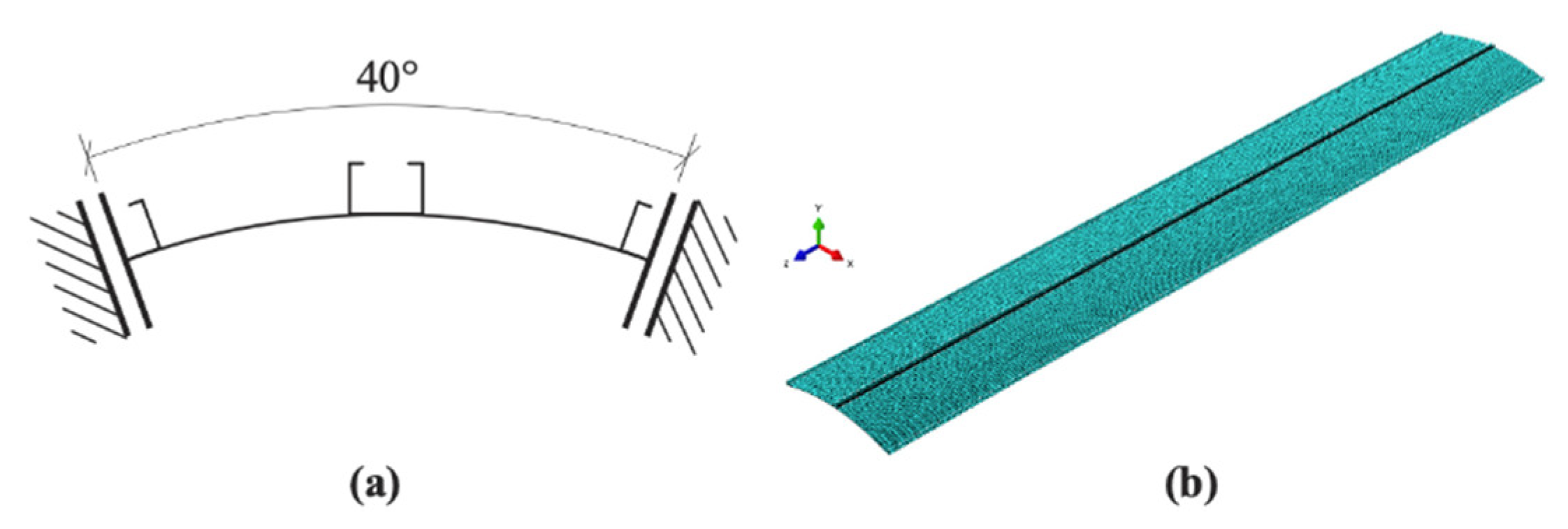
  152. Żmuda-Trzebiatowski, Ł.; Iwicki, P. Impact of Geometrical Imperfections on Estimation of Buckling and Limit Loads in a Silo Segment Using the Vibration Correlation Technique. Materials 2021, 14, 567. [Google Scholar] [CrossRef]
  153. Morelli, F.; Laguardia, R.; Faggella, M.; Piscini, A.; Gigliotti, R.; Salvatore, W. Ground motions and scaling techniques for 3D performance based seismic assessment of an industrial steel structure. Bull. Earthq. Eng. 2017, 16, 1179–1208. [Google Scholar] [CrossRef]
Figure 1. Examples of historical field stone silos (Perú, South America).
Applsci 12 03006 g001
Figure 2. View of silos battery used for grain storage with capacity of 3955 tons (Campo San Martino, Italy).
Applsci 12 03006 g002
Figure 3. Alternative arrangement for silos with different supporting structures.
Applsci 12 03006 g003
Figure 4. Silo and wall loads: (a) normal pressure; (b) vertical compression variation.
Applsci 12 03006 g004
Figure 6. Flow profiles: (a) mass flow; (b) funnel flow (pipe flow); (c) funnel flow (mixed flow); (d) funnel flow (eccentric pipe flow). Source: [102].
Applsci 12 03006 g006
Figure 7. Extreme damage in grain silo caused by asymmetric flow pattern. Source: [29].
Applsci 12 03006 g007
Figure 8. Potential failure mode due to buckling of unsupported wall in case of arching phenomenon. Source: [116].
Applsci 12 03006 g008
Figure 9. Steel silo of 24 m diameter split apart about two weeks after its first full capacity filling. Source: [116].
Applsci 12 03006 g009
Figure 10. Explosion of RC silo Battery (a) before explosion, (b) after explosion, Blaye, France, 1998. Source: [138].
Applsci 12 03006 g010
Figure 11. The studied silo segment: (a) scheme of boundary conditions (simplified); (b) numerical model. Source: [152].
Applsci 12 03006 g011
Table 1. Structural typology and arrangement of circular silos. H, R, and t indicates the height, the radius, and the thickness of the silos.
ReferenceTypologyMotivationStored MaterialH/RR/tSpecimenInvestigation Strategy
Jansseune et al. [38]Elevated steel silos discretely supported on columnsShell-column attachment, geometry improving.Granular material8200–1000Full scaleNumerical
Jansseune et al. [40]Elevated steel silos discretely supported on columnsFailure modes and connection geometrical enhancementsGranular material81000Full scaleNumerical
Doerich and Rotter [41]Elevated steel silos discretely supported on columnsShell-column attachment and behavior description.Granular material4600Full scaleNumerical
Topkaya et al. [9,10]
Zeybek et al. [37,43]
Elevated steel silosRing girder, stiffness criterion, arrangements of supporting system----Numerical
Winterstetter and Schmidt [55]Steel cylindrical shellGeometric imperfectionsEmpty2–494–148ScaledNumerical/experimental
Teng and Song [56]Steel cylindrical shellsEigenmode, imperfectionsEmpty3500 Numerical
Elishakoff et al. [58]Cylindrical shellsRandom imperfectionEmpty1.4–1.95386–681ScaledNumerical
Hühne et al. [61]
Castro et al. [32]
Composite cylindrical shellsGeometrical imperfection techniques- perturbation approachesEmpty---Numerical
Wagner et al. [59]Composite cylindrical shellsGeometrical imperfection techniques- perturbation approachesEmpty3330ScaledNumerical
Arbelo et al. [65]Composite cylindrical shellsGeometrical imperfection techniques- perturbation approachesEmpty2200, 540ScaledNumerical
Jiao et al. [62]Steel cylindrical shellImperfection, SPLA, and MPLAEmpty0.75–0.6667–833ScaledNumerical/experimental
Kriegesmann et al. [60]Composite cylindrical shellsProbabilistic imperfection approachEmpty2.04500ScaledNumerical/experimental
Khakimova et al. [63]Composite cylindrical shellsValidation of the SPLAEmpty2533ScaledNumerical/experimental
Pircher and Bridge [66]Steel circular silos, welding rolled steel strakes.Circumferential weld-induced imperfection, residual stresses.Empty3100Full-scaleNumerical
Jansseune et al. [7]Elevated steel silosImperfection forms modelling and investigationEmpty2–10100–1000ScaledNumerical
Ning and Pellegrino [17,49]Isotropic/orthotropic wavy shellsSilo cross-sectional shape optimization.-1.6, 2555.5, 195ScaledNumerical experimental
Rotter et al. [15]Thin-walled flat-bottom steel silosBuckling behavior under filling/discharging induced stressesGranular material620–900630–3940ScaledExperimental
Sadowski and Rotter [67]Flat-bottom steel silosEccentric discharge unsymmetrical pressure, slender silosWheat6500–1000Full scaleNumerical
Sadowski and Rotter [16]Flat-bottom steel silosEccentric discharge unsymmetrical pressure, slender silosCement10.4278–833Full scaleNumerical
Jäger-Cañás and Pasternak [18]Ring-stiffened steel cylindrical shellDesign ring stiffeners under axial compressionLiquid1125–10000Full scaleNumerical
Rejowski and Iwicki [78]Flat-bottom corrugated steel silosStability analysis of silo stiffenersBulk solids4.45347Full scaleNumerical
Li et al. [80]Ring-stiffened cylindrical steel shellRing-stiffeners arrangements, buckling behaviorEmpty0.78796ScaledNumerical/experimental
Batika et al. [19]Isotropic metallic cylindrical shell Elephant foot, buckling behavior, fibre-reinforced polymerEmpty11000Full scaleNumerical
Table 2. Earthquake loading and seismic response of silos. H, R, and t indicates the height, the radius, and the thickness of the silos.
ReferenceTypologyMotivationStored MaterialH/2RR/tSpecimenInvestigation StrategyModelling Stored MaterialDynamic Excitation
Rotter and Hull [4]Steel squat flat-bottom ground supported silosWall stresses, failure modesBulk solids0.125–2250–1000Full-scaleNumerical (steel)ElasticQuasi-static force
Younan and Veletsos [20]Rigid circular cylindrical tanksGrain-induced pressure on wallsViscoelastic solid0–5--AnalyticalHomogenous linear
viscoelastic
Harmonic excitation, earthquake record
Veletsos and Younan [5]Flexible circular cylindrical tanksWall flexibility responseViscoelastic solid0–1.5--AnalyticalHomogenous linear
viscoelastic
Harmonic excitation, earthquake record
Holler and Meskouris [86]Flat-bottom ground-supported silosProvisions of EN 1998-4, squat, and slender silosGranular material1, 5500, 600Full-scaleNumerical/ experimentalHypoplasticSynthetic records, harmonic excitation
Kanyilmaz and Castiglioni [35]Elevated steel silos groupSeismic isolation silosChemical
material
3.8146- 219Full-scaleNumerical(steel)Lumped distributed mass model [97]Spectra compatible
natural records
Castiglioni and Kanyilmaz [97]Elevated steel silosModelling techniquesGranular material1.75676Full-scaleNumerical(steel)Dracker-Prager, Lumped massScaled natural records
Guo et al. [82]Cylindrical-supporting RC silo (case study)Seismic assessment and designGranular material2.927.3Full-scaleNumerical (RC)HypoplasticNatural records
Nateghi and Yakhchalian [89]RC flat-bottom ground supported silosEffect of granular material–structure interactionGranular material216.6Full-scaleNumerical (RC)HypoplasticNatural records
Yakhchalian and Nateghi [88] Steel flat-bottom ground supported silosEffect of granular material–structure interactionGranular material1–5120–500Full-scaleNumerical(steel)HypoplasticNatural records
Silvestri et al. [21]Flat-bottom ground-supported silosBehavior of the stored grainGrain-like material1-Full-scaleAnalyticalAnalyticalTime-constant records
Pieraccini et at. [90]Flat-bottom ground-supported silosAnalytical dynamic responseGrain-like material0.25–1-Full-scale
AnalyticalAnalyticalTime-constant records
Pieraccini et al. [91]Flat-bottom ground-supported silosVibration periods estimationCoal, Ballottini glassvariant-variantAnalyticalAnalyticalHarmonic signal, white noise
Silvestri et al. [85]Flat-bottom ground-supported silosAnalytical dynamic responseBallottini glass0–1200ScaledExperimentalAnalyticalHarmonic signal, white noise
Durmuş and Livaoglu [92]RC flat-bottom ground supported siloSoil–structure interactionWheat0.75, 1.25100Full scaleAnalytical/NumericalVisco-elastoplastic, hypoplasticNatural records
Butenweg et al. [93]Flat-bottom ground-supported steel silosSeismic analysis of silosGranular bulk materials1, 5100, 75Full scaleNumericalHypoplasticStatic equivalent loads, Synthetic records
Mehretehran and Maleki [83,94]Flat-bottom ground-supported steel silosDynamic buckling behaviorCamacho wheat0.72–2.25
0.8–2.5
500–1250
500–2500
Full-scaleNumericalDrucker-PragerNatural records
Silvestri et al. [95]Flat-bottom ground-supported steel silos, corrugated wallsStatic pressure, dynamic propertiesWheat0.91820Full-scaleExperimentalAnalyticalHarmonic signal, white noise
Jian et al. [96]Flat-bottom ground-supported flexible steel silos (shallow)Dynamic response, energy dissipation capacityWheat0–1400ScaledExperimentalAnalyticalNatural records
Table 3. Main failures modes and causes of silos.
ReferenceTypologyMotivationFailure CausesFailure ModesUsageContent MaterialFull/Partial FailureFailure Reason
Mai [28]RC silosFailures in RC silos, durability, cause, mechanisms, strengthening-Multi-modes failure-Different cases with various dimensions
Rotter [113]Silos and tanks
(RC, steel)
Different typologies and imposed actions-Multi-modes failureIndustrialDifferent cases with various dimensions
Maraveas [114]RC silos (cast-in-place, precast silos)Strengthen strategies-Multi-modes failureAgriculture sectorDifferent cases with various dimensions
Rotter [115]Steel silosDesign rules formulationHigh internal pressureElephant’s foot bucklingGeneralDifferent cases with various dimensions
Carson and Holmes [116]RC, steel silosFailure reasonsDesign, construction, utilization-Industrial (power plant)Fly ashFull collapseThermal ratcheting, construction cost-cutting measures
Carson and Jenkyn [117] RC, steel silosFailure reasons, causes, and the countermeasuresDesign, construction, utilization, maintenanceMulti-modes failureGeneralDifferent cases with various dimensions
Zaccari and Cudemo [29]Steel silosFailure reasons, strengthen strategiesDesign deficienciesBuckling failureIndustrial
(power plant)
LimestoneHuge deformationEccentric discharge flow mis-assessment
Dogangun et al. [70]RC, precast concrete, steel silosFailure accidentsExplosions,
asymmetrical loads, soil failure, earthquakes.
Multi-modes failureIndustry (food)CornFull collapseBursting
Industrial
(power plant)
CoalPartial collapseInternal failure
Oxygen storgeLiquefied oxygenPartial collapseSupporting system failure
Puzrin et al. [123]RC silos battery Failure of massive grain elevatorSoil failureSoil failureGrain storage for shipmentGrainPartial soil failureGeotechnical design deficiency
Basone et al. [130]Steel tankReducing seismic failure risk, base isolationEarthquakeSeismic damagesFuel storageLiquid-High pressure induced by ground motion
Kanyilmaz and Castiglioni [35]Elevated steel silo group Reducing seismic failure risk, base isolationEarthquakeSeismic damageGranular material storageSodium percarbonatePartial failureSteel supporting system failure
Sassine et al. [133]Cylindrical steel tanksTank wall stresses over thermal cyclesthermal cycling and fluctuatingThermal ratchetingIndustrial
(power plant)
GranularFull collapseThermal ratcheting
Tascón [139]RC silosReducing explosion risk, ventilation systemDust explosionExplosionBarley and wheat flourDifferent cases with various dimensions
Table 4. Main failures modes and causes of silos of silos. H, R, and t indicates the height, the radius, and the thickness of the silos.
ReferenceTypologyMotivationStored MaterialH/RR/tFull Scale/ScaledInvestigation Strategy
Rosen and Singer [148]Stiffened isotropic cylindrical shell, elastic edge restraints.Boundary condition definition, system under axial loadsEmpty1.25–1.5486–520ScaledExperimental
Singer and Abramovich [149]Stiffened isotropic cylindrical shell, realistic boundary conditionsPractical boundary condition definition, system under axial loadsEmpty0.92–1.28467–477ScaledExperimental
Arbelo et al. [145]Unstiffened cylindrical shell (composite-carbon fiber fabric)VCT for real boundary condition estimation, thin-walled shell structuresEmpty1300ScaledExperimental
VCT for real boundary condition estimation, thin-walled shell structuresEmpty2408–1080ScaledNumerical
Kalnins et al. [143]Unstiffened cylindrical shell (steel and composite)VCT for real boundary condition estimation, thin-walled shell structuresEmpty2478–800ScaledExperimental
Skukis et al. [146]Unstiffened cylindrical shell (composite)VCT for real boundary condition estimation, thin-walled shell structuresEmpty2478ScaledExperimental/ Numerical
Skukis et al. [150]Isotropic cylindrical shell with cut-outsVCT for buckling capacity estimationEmpty0.92920ScaledExperimental
Franzoni et al. [151]Isotropic imperfection-sensitive cylindrical shellsVCT verification investigation, relationship between compressive load/natural frequency variationEmpty2500–800ScaledAnalytical/numerical
Zmuda-Trzebiatowski and Iwicki [152]Steel stiffened corrugated silosApplicability of the VCT, estimation of the buckling load of silos.Empty4.35360Full scaleNumerical
Ding et al. [31]
Ding et al. [11]
Large-scale steel cylindrical silosImperfection measurement, Surface profile measurement system Empty1.96480–1000 Full scaleExperimental
Morelli et al. [153]Elevated steel silo groupPerformance-based earthquake assessmentFiltered dust--Full scaleNumerical
Publisher’s Note: MDPI stays neutral with regard to jurisdictional claims in published maps and institutional affiliations.

