
A New Methodology for Type Synthesis of Planar Linkages for Exoskeletons up to Five Angular Outputs


Abstract
:1. Introduction
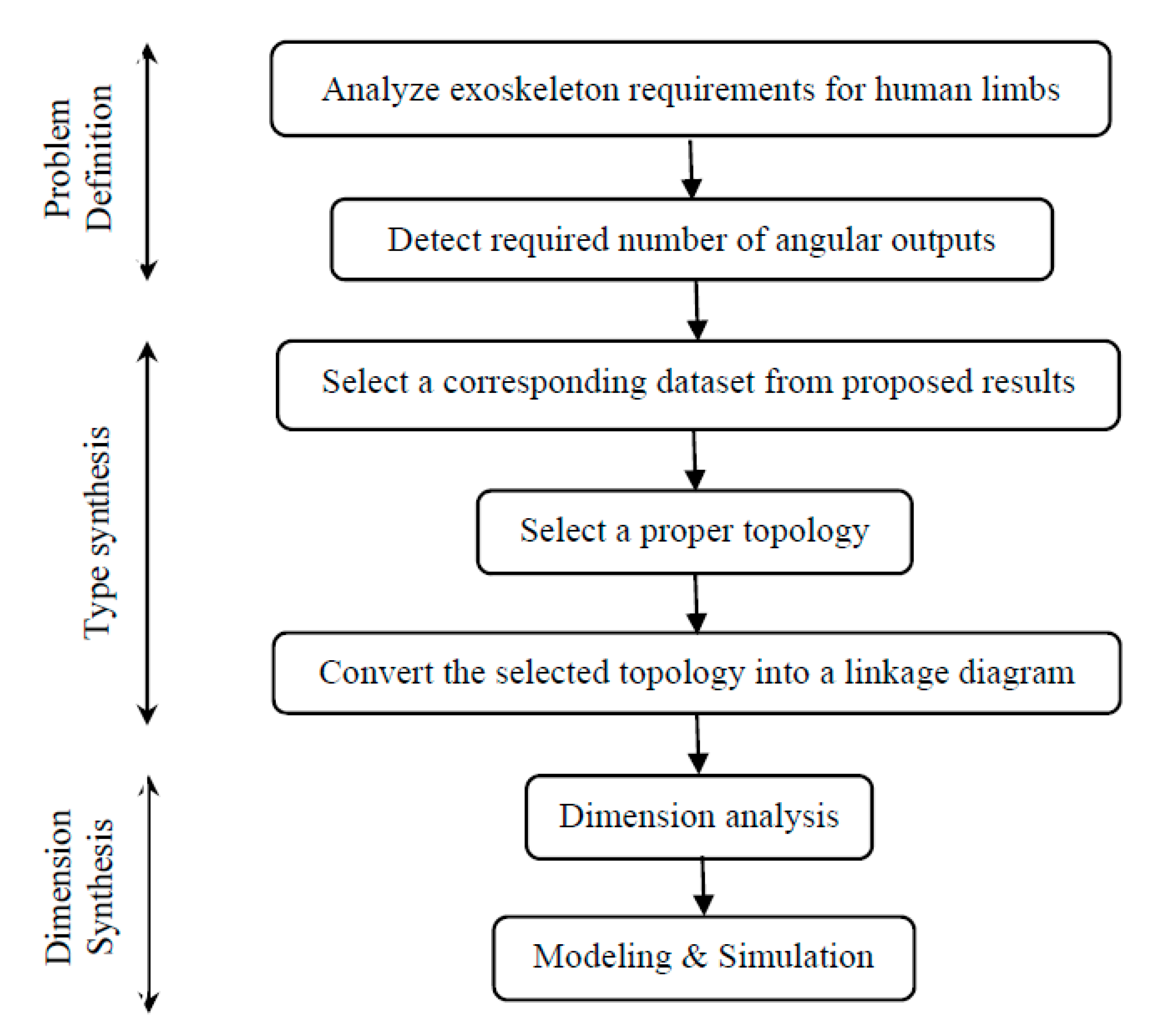
2. Design Basics
- Type of human limb (lower limb, upper limb, or finger);
- Type of required motion;
- Number of human joints that are required to be rehabilitated and their trajectory;
- The available workspace for exoskeleton fixation;
- The ability of patient to carry the proposed mechanism.
3. Modified Graph Theory
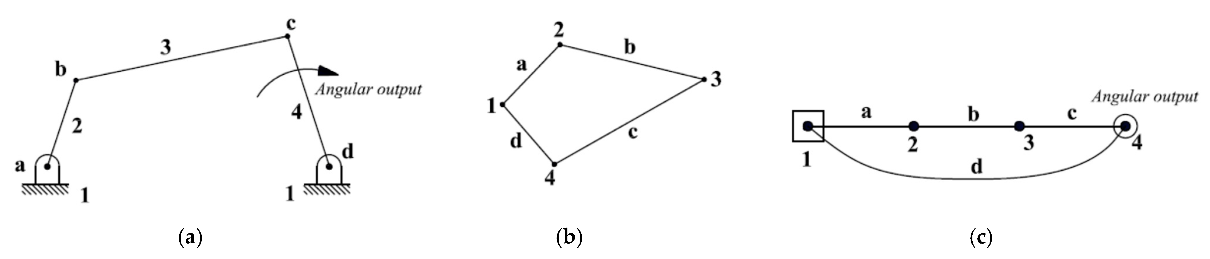
- Ground link (1) is denoted as a square.
- The output link (4) is denoted as a hollow circle.
- Other links (2, 3) are denoted as vertices.
- The connection between the ground link and output link is denoted by a curved edge (d).
- Other joints are denoted as solid edges (a, b, c) as shown in Figure 1c.
4. Type Synthesis
4.1. Parallel Connection Method
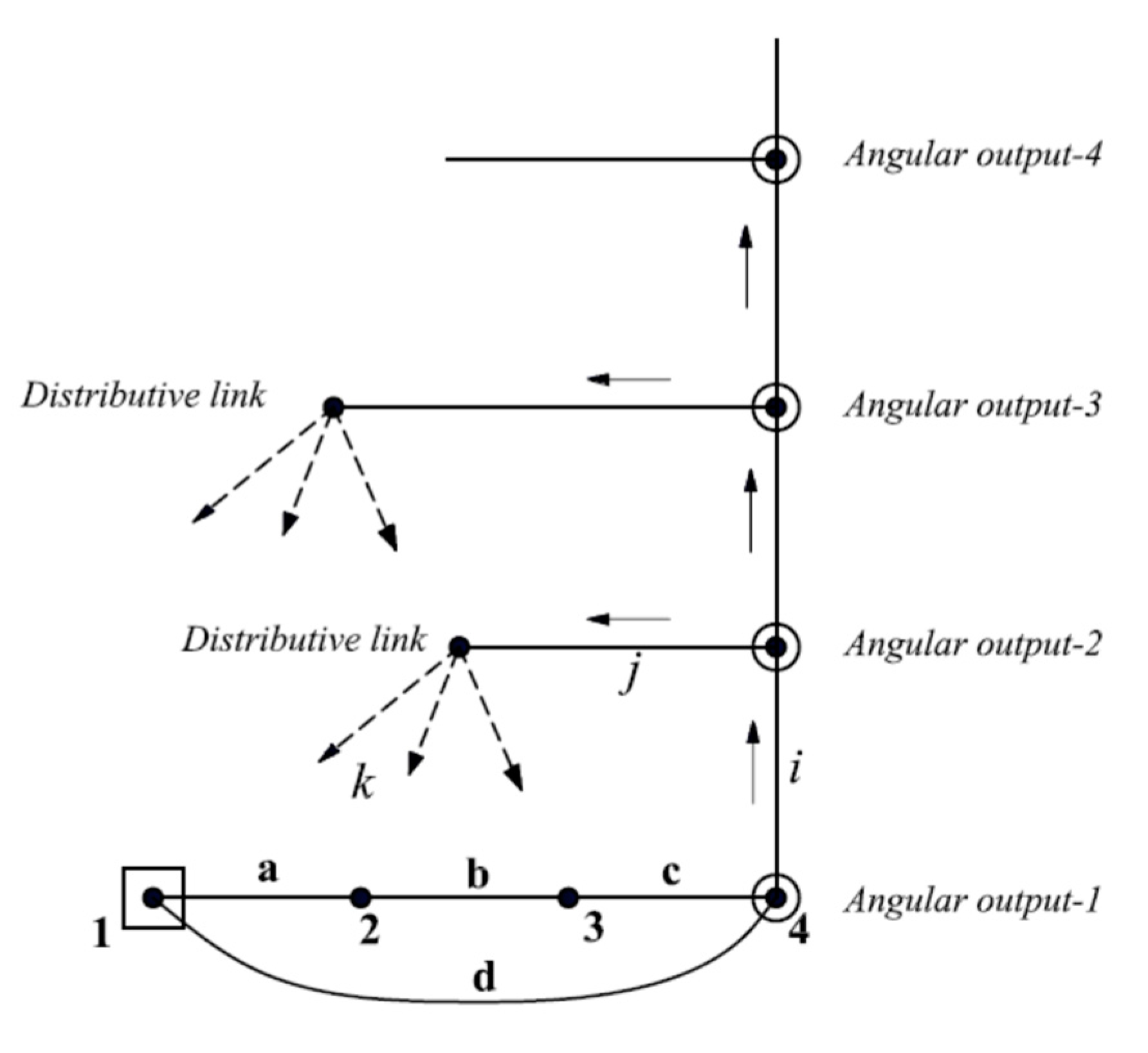
- All angular output links should be represented usually at the right of the graph.
- Adding the RRR dyad starts from the last presented angular output link (including two links and three revolute joints).
- The first additional link is located directly above the current output link to represent the ‘newer angular output’. This link is represented as a hollow circle. Therefore, all angular outputs are located in parallel arrangement as shown in Figure 2.
- The second additional link is located at the left of the new angular output link. This link is denoted by ‘distributive link’.
- Joints between the previous output, newer output, and distributive links are represented by solid edges (i, j). In other words, angular outputs are presented vertically above each other.
- The last revolute joint (k) has some alternatives to connect the distributive link with other links, excluding the connections that produce rigid sub-chains. These alternatives generate the available topological graphs that can achieve the required number of angular output motions.
4.2. Series Connection Method
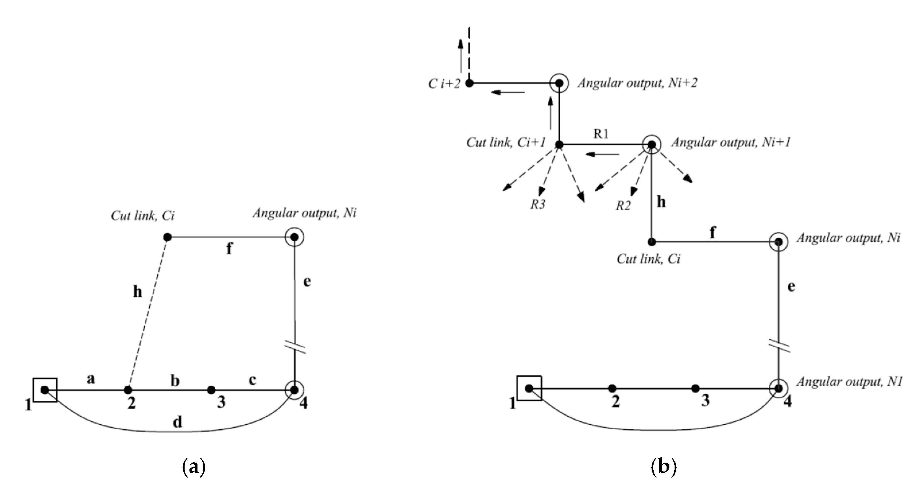
- One of the linkage configurations, with a specific number of angular outputs, is selected as illustrated in Figure 3a. The selected configuration has a latest RRR dyad that contains angular output ‘Ni’, link ‘Ci’, which is denoted as ‘cut link’, and revolute joints namely: e, f, and h.
- Starting from the cut link, ‘Ci’, joint ‘h’ is deleted and reconnected directly with the newer angular output ‘Ni+1’ which is located directly above the present cut link ‘Ci’ as shown in Figure 3b.
- The second additional link,’Ci+1’, is located at the left of new angular output ‘Ni+1’.
- The joint between the newer output ‘Ni+1’ and its adjacent cut link ‘Ci+1’ is represented by a solid edge ‘R1’. In other words, angular outputs are presented diagonally.
- The remaining two revolute joints (R2, R3) have some alternatives to connect newer output and its adjacent cut link with original links in the linkage graph. That produces some available topological graphs that can achieve the required number of angular output motions, noting that some connections that produce rigid sub-chains should be excluded.
- Additional angular output can be obtained by repeating steps 2–5 so that all angular outputs are located in stepped series arrangement as shown in Figure 3.
4.3. Generation of Two Angular Outputs Using Parallel Connection
- First angular output link is represented at the right of the graph (link-4).
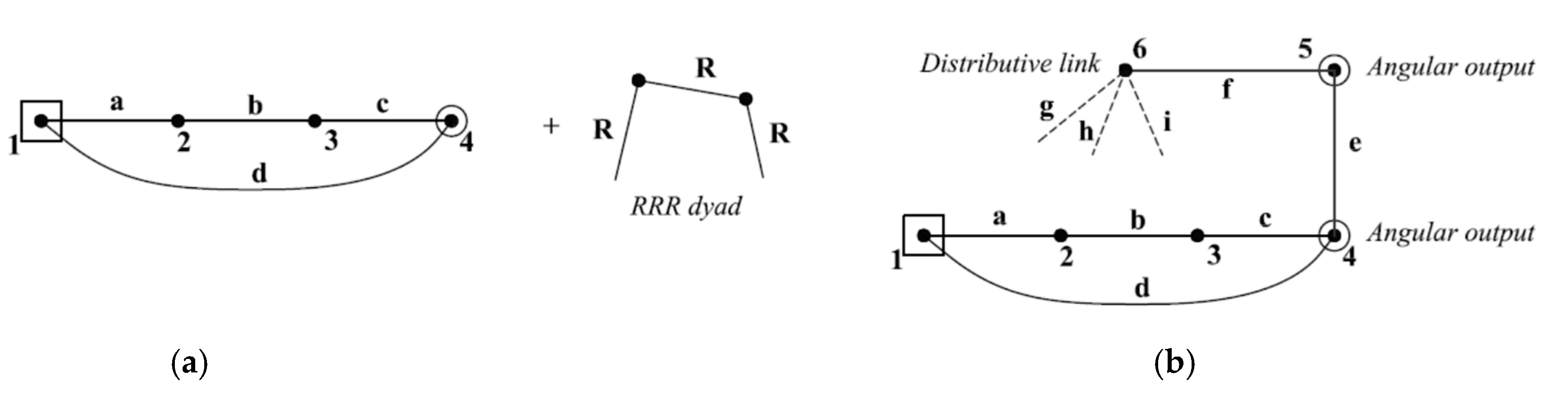
- Adding RRR dyad starts from link-4 (including two additional links: 5, 6).
- Link-5 is located directly above link-4 to represent the second angular output link as shown in Figure 4b.
- The distributive link-6 is located at the left of link-5 as shown in Figure 4b.
- Joints between links (4, 5 and 6) are represented by solid edges (e, f) as shown in Figure 4b.
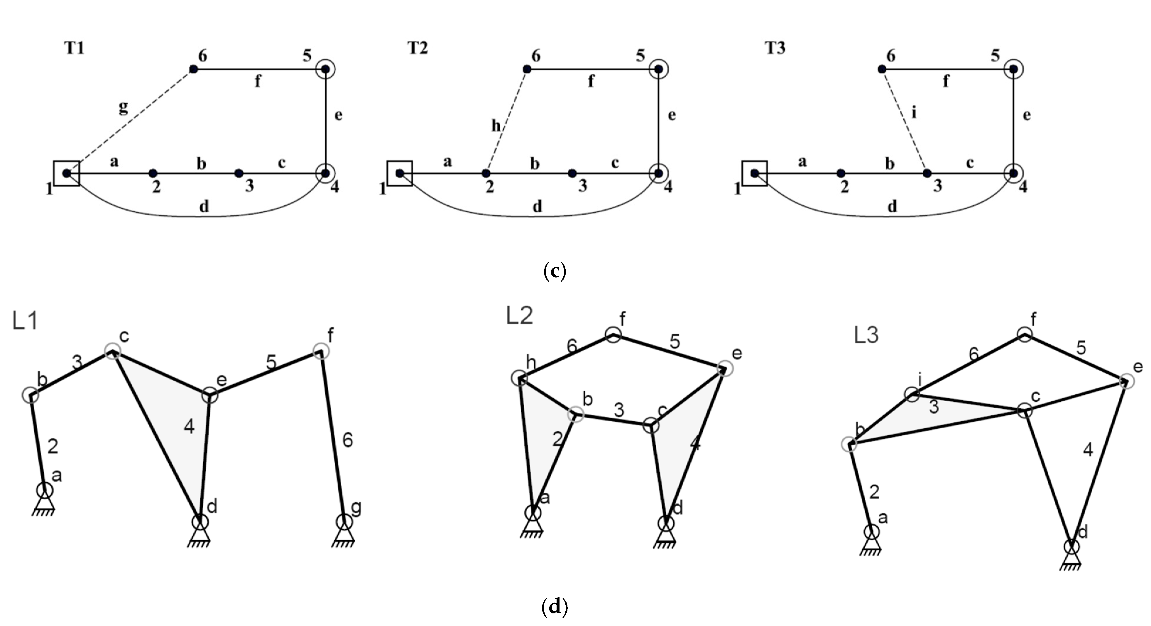
- The last revolute joint has three alternatives to connect distributive link-6 with other links (joints g, h, i) excluding the connections that produce rigid sub-chains. These alternatives generate three available topological graphs that can achieve two angular output motions as shown in Figure 4c.
- Linkage diagrams, shown in Figure 4d, can be obtained from their corresponding topological graphs as illustrated in Section 4.4.
4.4. Sketching of Linkage Diagrams
- The original four-bar linkage is sketched containing two fixed pivots, binary links (2, 3, 4), and four revolute joints (a, b, c, d).
- According to topology ‘T1’, link-1 is connected with three links (2, 4, 6). Therefore, a third pivot is added which is connected with a binary link-6 by a revolute joint ‘g’.
- According to topology ‘T1’, link-4 is connected with three links (1, 3, 5). Therefore, link-4 is converted into a ternary link which is connected with a binary link-5 by a revolute joint ‘e’.
- Two binary links (5 and 6) are connected by a revolute joint ‘f’.
5. Generation of Multiple Angular Outputs
5.1. Generation of Three Angular Outputs Using Parallel Connection
- The existing angular output links are represented at the right of the graph (links 4 and 5) as shown in Figure 5a.
- Adding the RRR dyad starts from link-5 (including two additional links: 7, 8).
- Link-7 is located directly above link-5 as a third angular output link as shown in Figure 5b.
- The distributive link-8 is located at the left of link-7.
- Joints between links (5, 7 and 8) are represented by solid edges (j, k) as shown in Figure 5b.
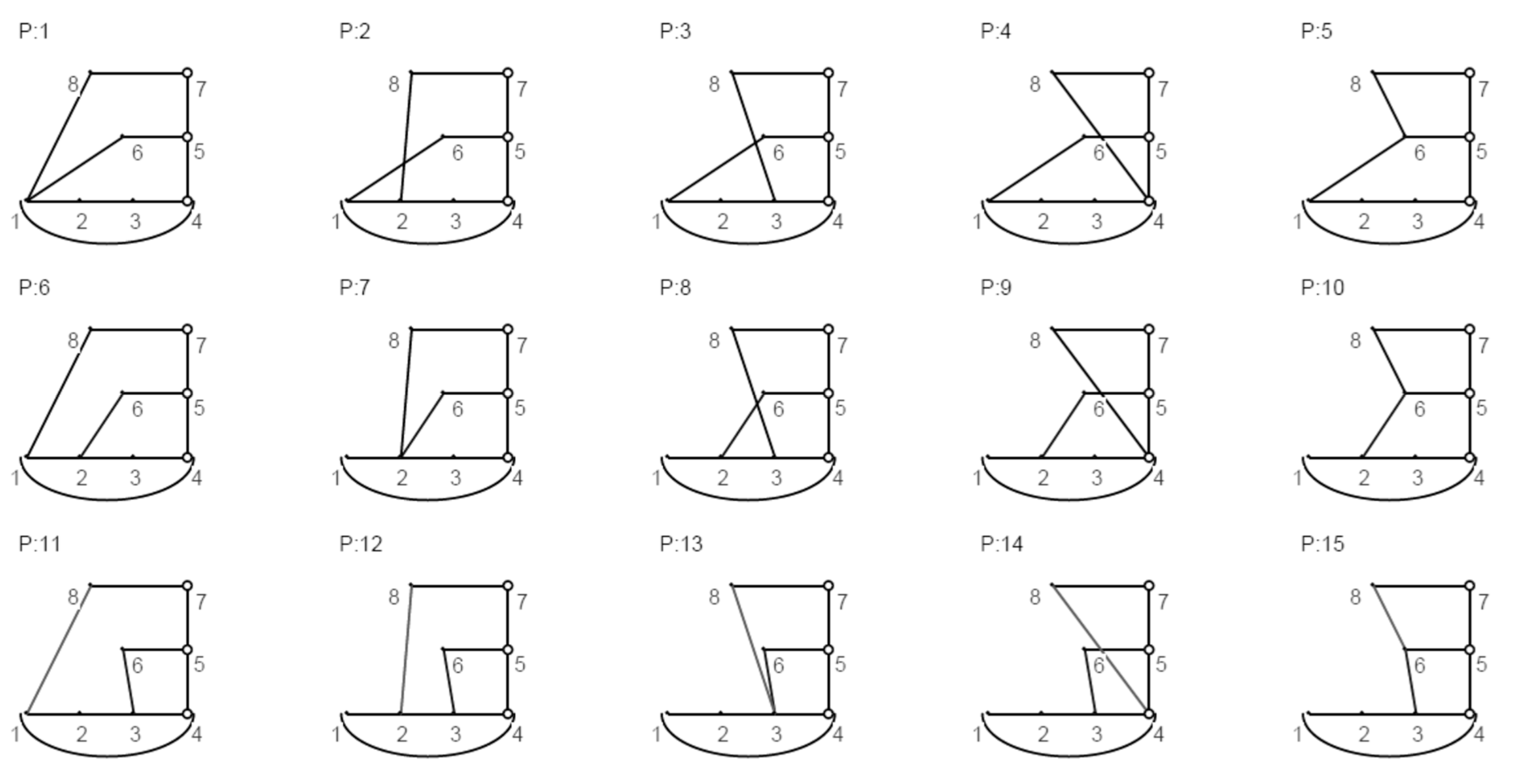
- The last revolute joint, l, has five alternatives to connect distributive link-8 with other links in the original linkage graph, excluding the connections that produce rigid sub-chains. These alternatives generate five available eight-bar topological graphs that can achieve three angular output motions as shown in Figure 5c.
- Linkage diagrams can be constructed from their corresponding topological graphs as illustrated in Section 4.4. Some of these linkage diagrams are shown in Figure 5d.
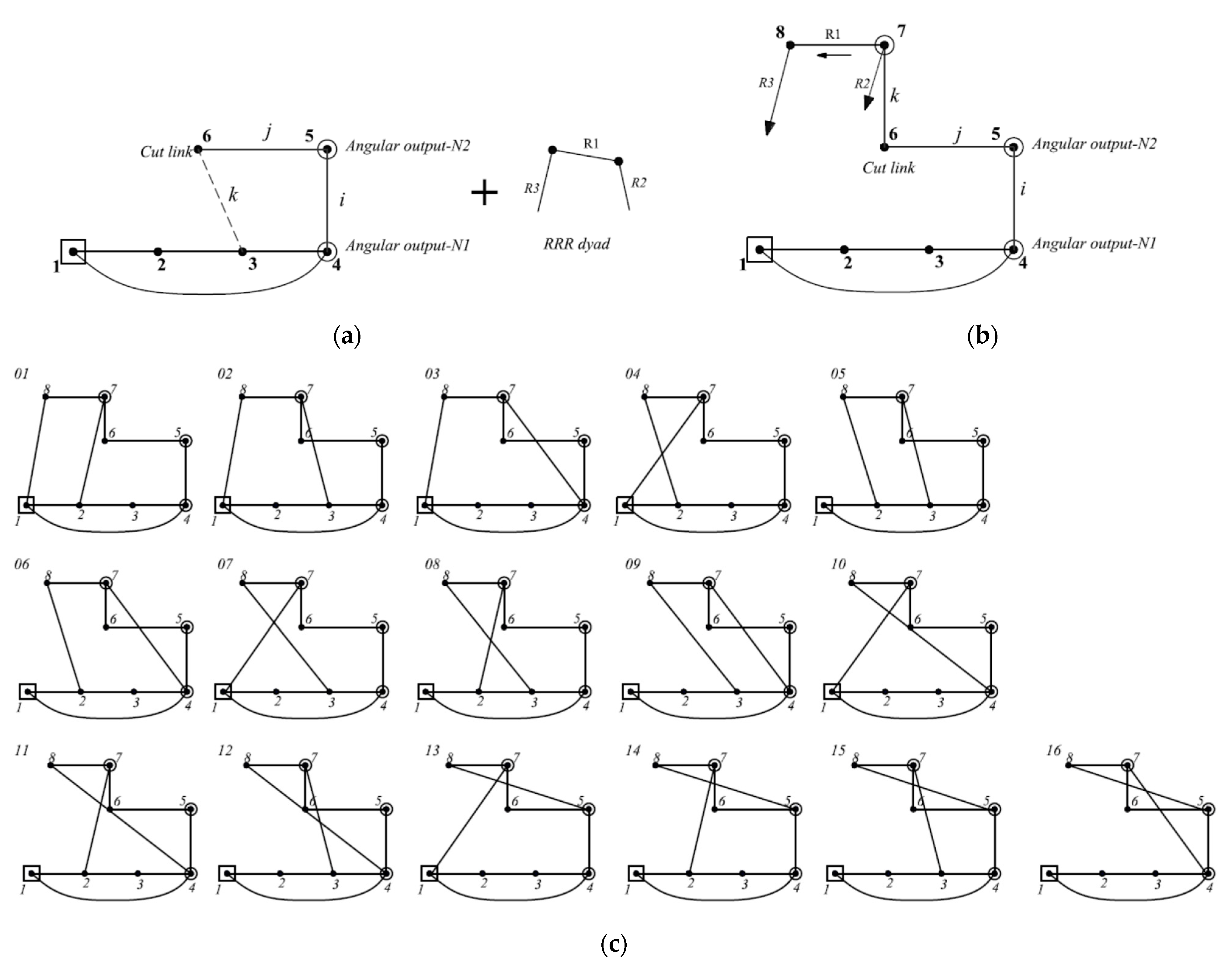
5.2. Generation of Three Angular Outputs Using Series Connection
- Link ‘7’ is added directly above the current cut link ‘6’ to present the newer angular output as a hollow circle as illustrated in Figure 6b.
- Joint ‘k’ is deleted and reconnected directly with the newer angular output ‘7’.
- Link-8 is added at the left of the new angular output as shown in Figure 6b.
- The joint between the newer output ‘7’ and its adjacent cut link ‘8’ is represented by solid edge ‘R1’.
- The remaining two revolute joints (R2, R3) have some alternatives to connect newer output and its adjacent cut link with other links, excluding the connections that produce rigid sub-chains. These alternatives generate the available topological graphs that can achieve the required number of angular output motions as shown in Figure 6c.
- Linkage diagrams can be established from their corresponding topological graphs as illustrated in Section 4.4.
6. Results
- ▪
- A total of three six-bar linkages with up to two angular outputs, illustrated in Figure 3.
- ▪
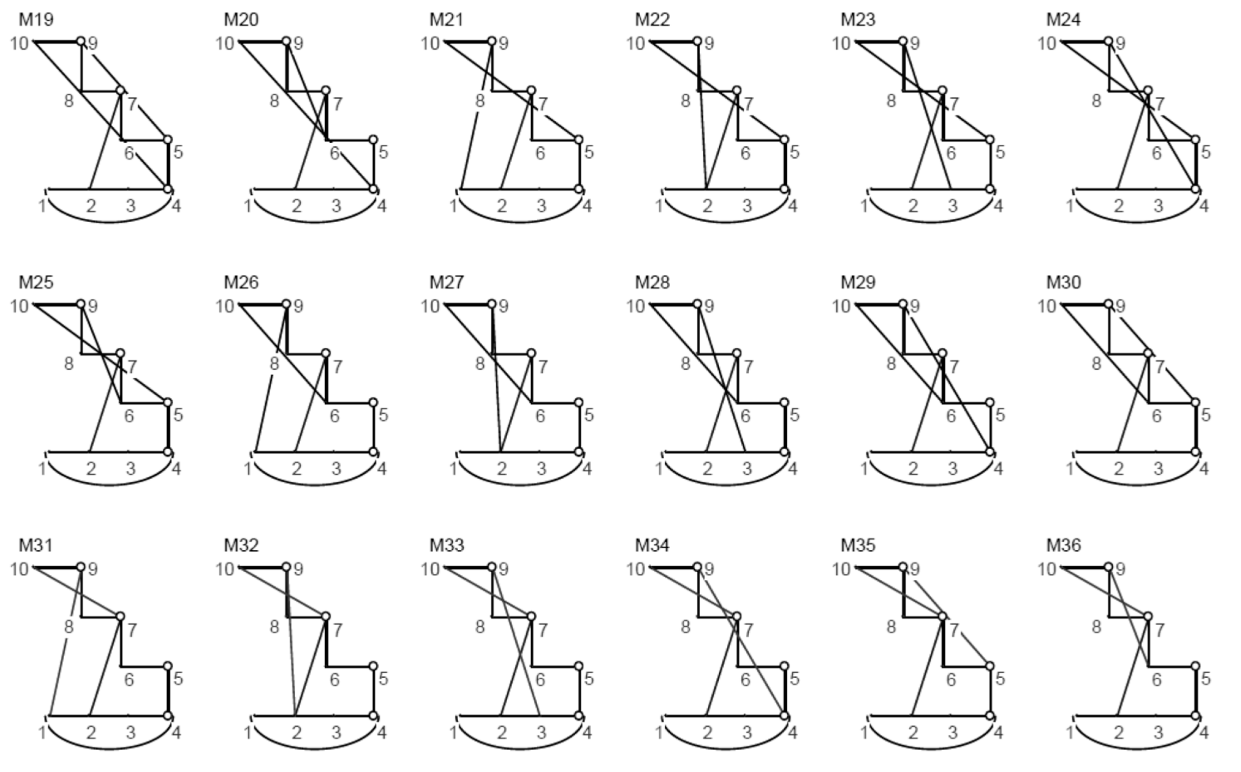
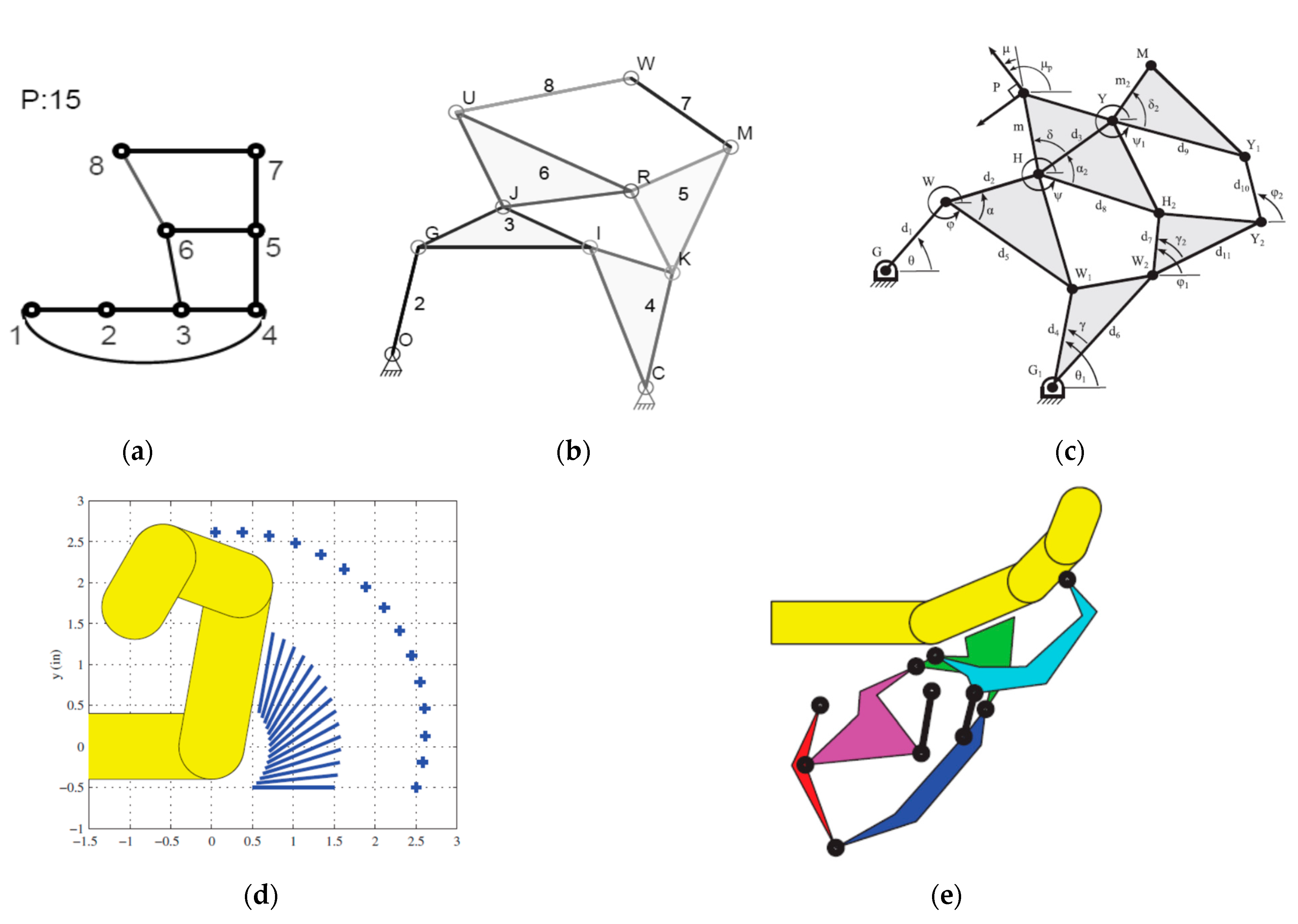
- A total of 15 eight-bar linkages with up to three angular outputs using parallel connection, illustrated in Figure A1 (given in Appendix A).
- ▪
- A total of 16 ten-bar linkages with up to three angular outputs using series connection, illustrated in Figure 6c.
- ▪
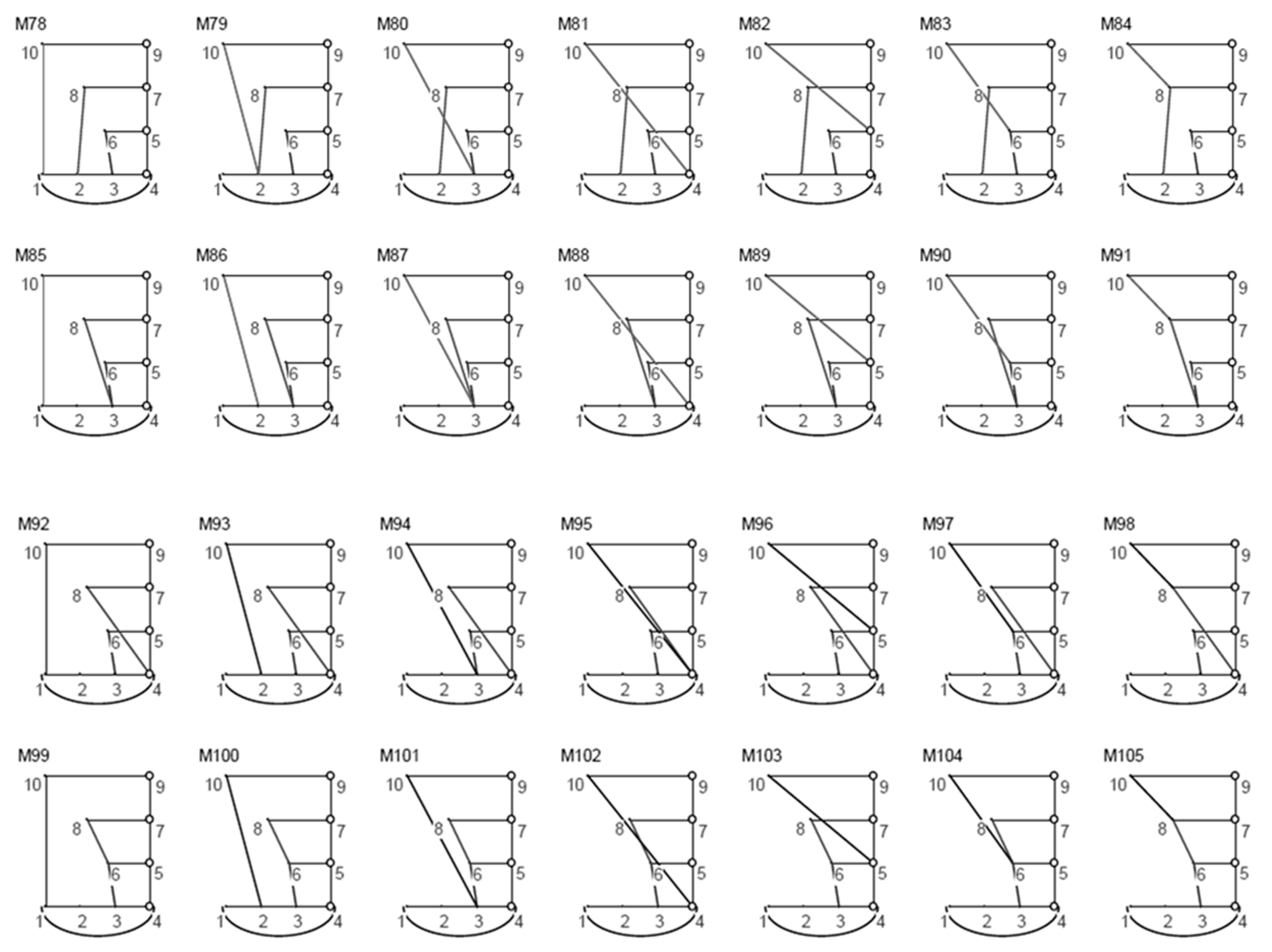
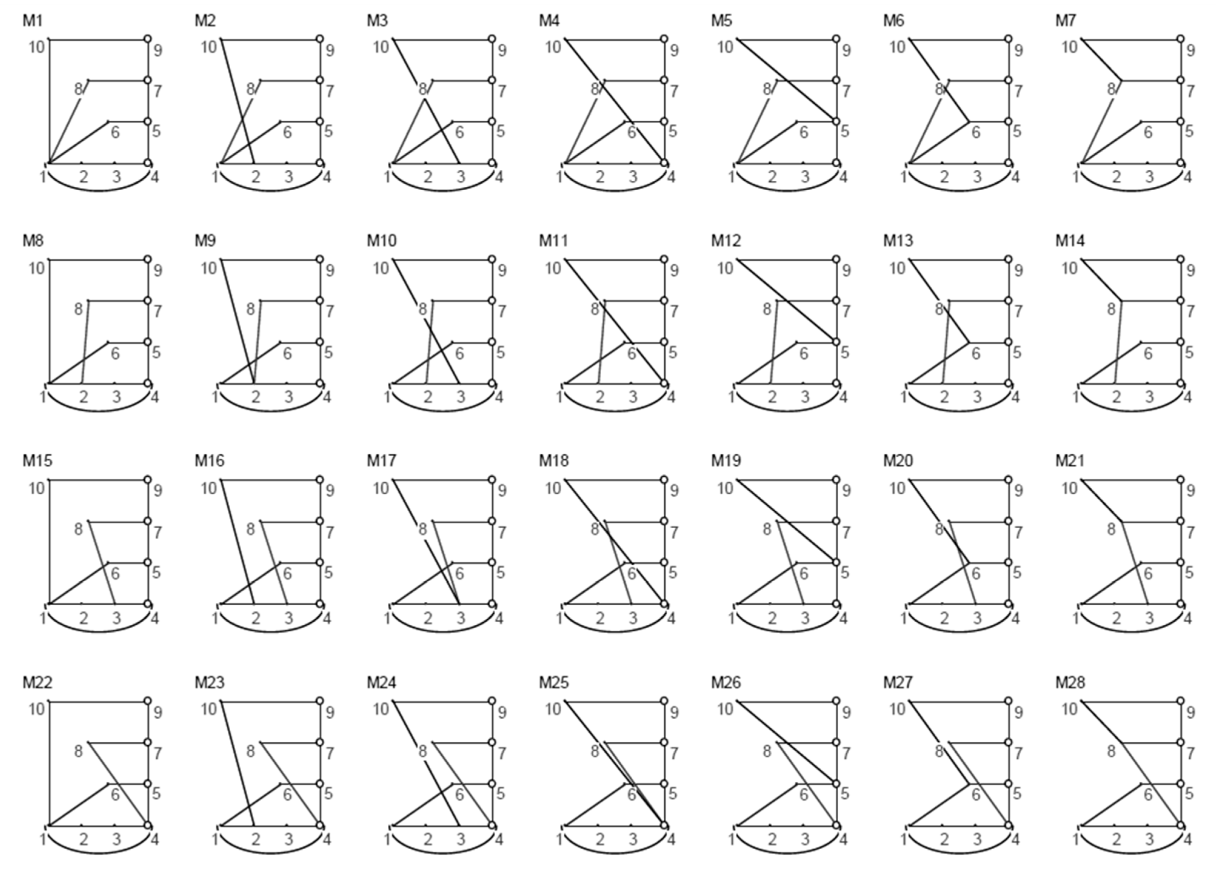
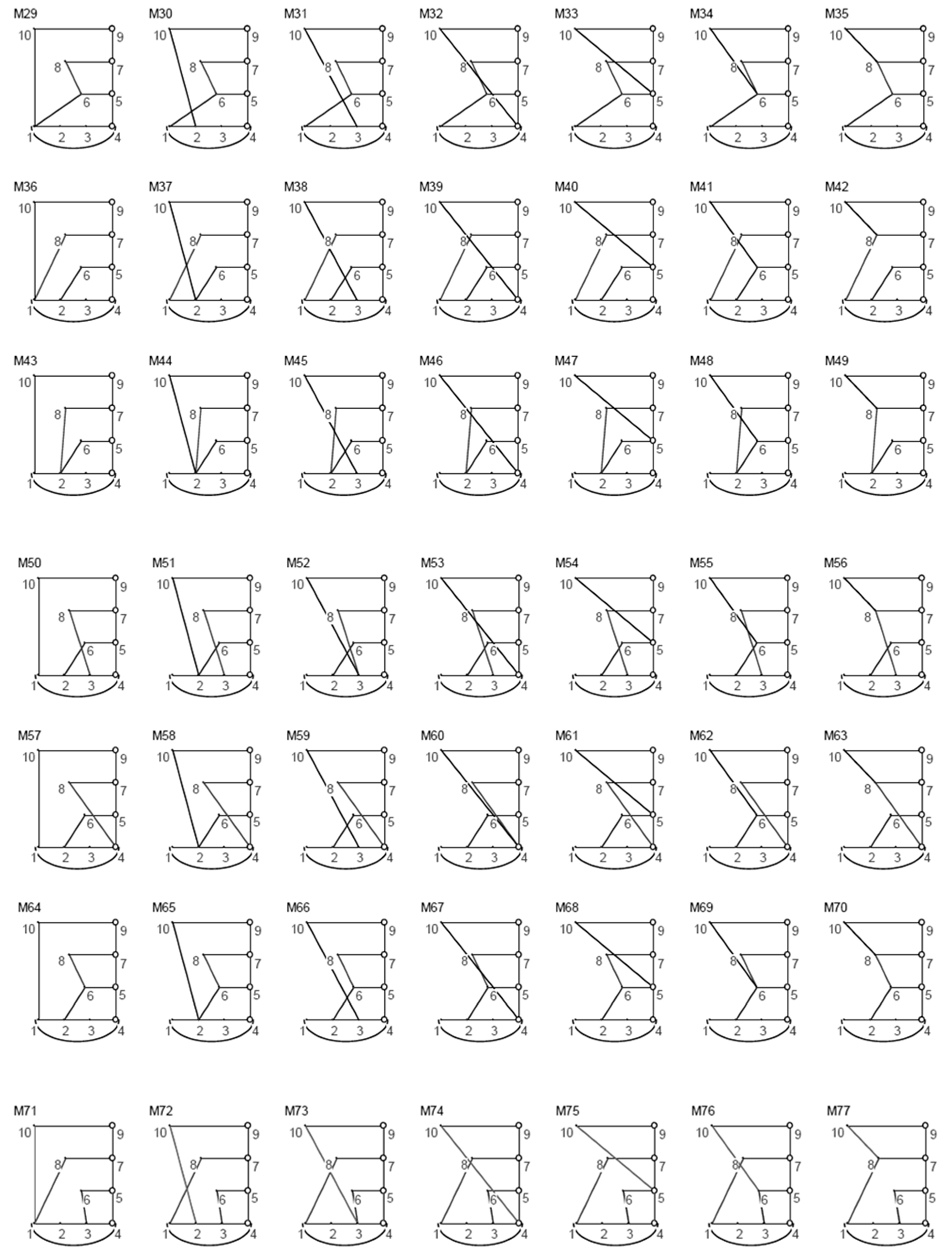
- A total of 105 ten-bar linkages with up to four angular outputs using parallel connection, illustrated in Figure A2 (given in Appendix A).
- ▪
- A total of 18 (out of 576) ten-bar linkages with up to four angular outputs using series connection, illustrated in Figure A3 (given in Appendix A).
- ▪
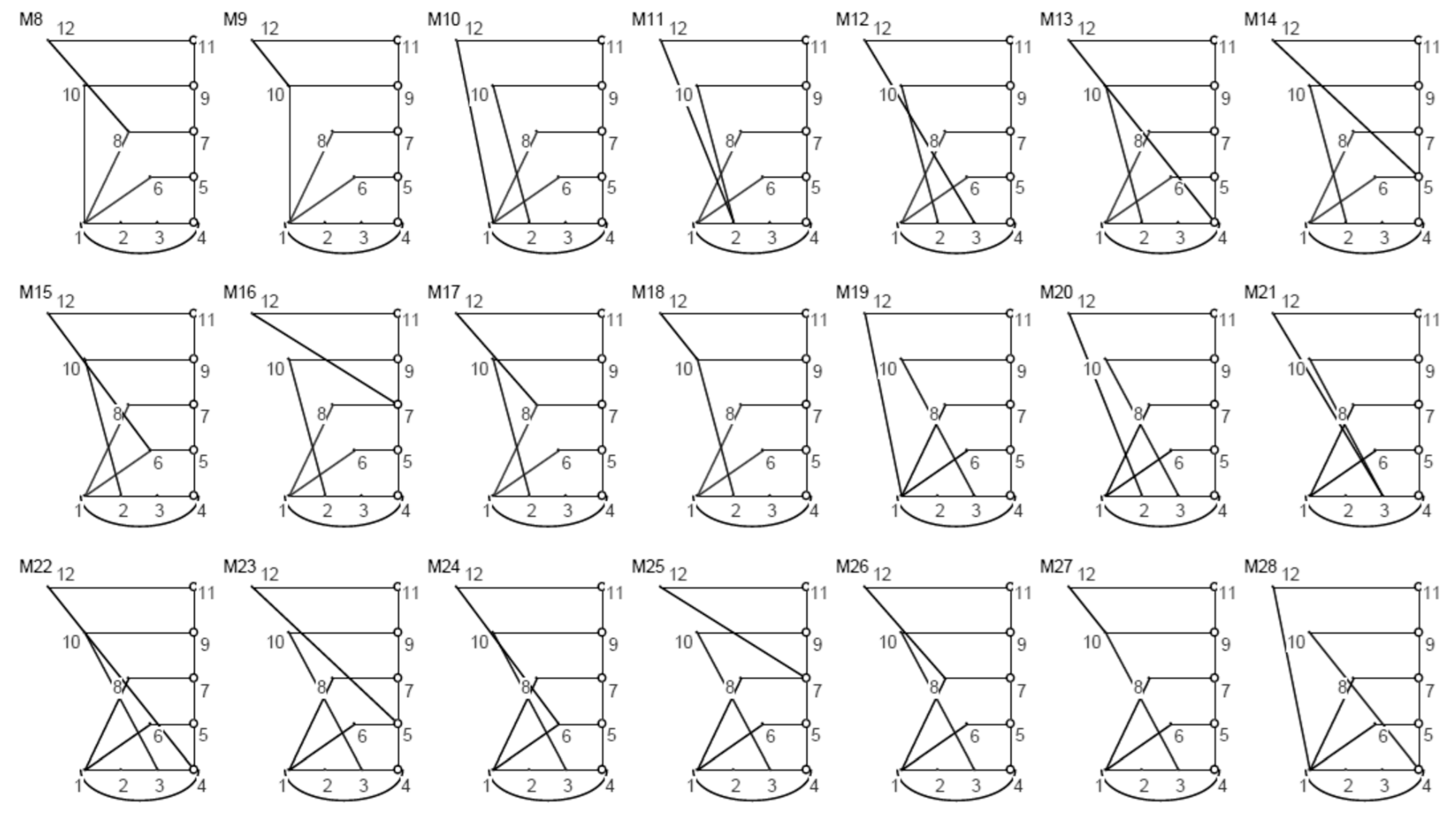
- A total of 21 (out of 945) twelve-bar linkages with up to five angular outputs using parallel connection, illustrated in Figure A4 (given in Appendix A).
6.1. Example-1
6.2. Example-2
7. Conclusions
Author Contributions
Funding
Institutional Review Board Statement
Informed Consent Statement
Data Availability Statement
Acknowledgments
Conflicts of Interest
Appendix A


References
- Buchsbaum, F.; Freudenstein, F. Synthesis of Kinematic Structure of Geared Kinematic Chains and Other Mechanisms. Mech. Mach. Theory 1970, 5, 357–392. [Google Scholar] [CrossRef]
- Kim, Y.Y.; Jang, G.-W.; Park, J.H.; Hyun, J.S.; Nam, S.J. Automatic Synthesis of a Planar Linkage Mechanism with Revolute Joints by Using Spring-Connected Rigid Block Models. ASME J. Mech. Des. 2007, 129, 930. [Google Scholar] [CrossRef]
- Ding, H.; Yang, W.; Huang, P.; Kecskeméthy, A. Automatic Structural Synthesis of Planar Multiple Joint Kinematic Chains. J. Mech. Des. 2013, 135, 091007. [Google Scholar] [CrossRef]
- Ding, H.; Huang, P.; Yang, W.; Kecskeméthy, A. Automatic generation of the complete set of planar kinematic chains with up to six independent loops and up to 19 links. Mech. Mach. Theory 2016, 96, 75–93. [Google Scholar] [CrossRef]
- Yang, W.; Ding, H.; Lai, X.; Wu, M. Automatic synthesis of planar simple joint mechanisms with up to 19 links. Mech. Mach. Theory 2017, 113, 193–207. [Google Scholar] [CrossRef]
- Olson, D.G.; Erdman, A.G.; Riley, D.R. A Systematic Procedure for Type Synthesis of Mechanisms with Literature Review Literaturbe- Sprechung. Mech. Mach. Theory 1985, 20, 285–295. [Google Scholar] [CrossRef]
- Ding, H.; Hou, F.; Kecskeméthy, A.; Huang, Z. Synthesis of the whole family of planar 1-DOF kinematic chains and creation of their atlas database. Mech. Mach. Theory 2012, 47, 1–15. [Google Scholar] [CrossRef]
- Freudenstein, F.; Dobjansky, L. Some Applications of Graph Theory to the Structural Analysis of Mechanisms. ASME J. Eng. Ind. 1967, 89, 153–158. [Google Scholar] [CrossRef]
- Manolescu, N. A Method Based on Baranov Trusses, and Using Graph Theory to Find the Set of Planar Jointed Kinematic Chains and Mechanisms. Mech. Mach. Theory 1973, 8, 3–22. [Google Scholar] [CrossRef]
- Huang, P.; Ding, H. Structural synthesis of Baranov trusses with up to 13 links. ASME J. Mech. Des. 2019, 141, 072301. [Google Scholar] [CrossRef]
- Han, J.; Shi, S. A novel methodology for determining the singularities of planar linkages based on Assur groups. Mech. Mach. Theory 2020, 147, 103751. [Google Scholar] [CrossRef]
- Huang, P.; Ding, H. Structural synthesis of Assur groups with up to 12 links and creation of their classified databases. Mech. Mach. Theory 2020, 145, 103668. [Google Scholar] [CrossRef]
- Sun, J.; Liu, W.; Chu, J. Dimensional Synthesis of Open Path Generator of Four-Bar Mechanisms Using the Haar Wavelet. ASME J. Mech. Des. 2015, 137, 082303. [Google Scholar] [CrossRef]
- Lin, W.-Y. Optimum Synthesis of Planar Mechanisms for Path Generation Based on a Combined Discrete Fourier Descriptor. ASME J. Mech. Robot. 2015, 7, 041023. [Google Scholar] [CrossRef]
- Kawamura, S.; Ito, K. A New Type of Master Robot for Teleoperation Using a Radial Wire Drive System. In Proceedings of the IEEE/RSJ International Conference on Intelligent Robots and Systems’ 93 (IROS’93), Yokohama, Japan, 26–30 July 1993; pp. 55–60. [Google Scholar]
- Mao, Y.; Agrawal, S.K. Design of a Cable-Driven Arm Exoskeleton (CAREX) for Neural Rehabilitation. IEEE Trans. Robot. 2012, 28, 922–931. [Google Scholar] [CrossRef]
- Zi, B.; Wang, B.; Wang, D. Design and analysis of a novel cable-actuated palletizing robot. Int. J. Adv. Robot. Syst. 2017, 14. [Google Scholar] [CrossRef]
- Robson, N.; Soh, G.S. Geometric design of eight-bar wearable devices based on limb physiological contact task. Mech. Mach. Theory 2016, 100, 358–367. [Google Scholar] [CrossRef] [Green Version]
- Akgun, G.; Kaplanoglu, E.; Cetin, A.E.; Ulkir, O. Mechanical Design of Exoskeleton for Hand Therapeutic Rehabilitation. Quest J. J. Res. Mech. Eng. 2018, 4, 9–17. [Google Scholar]
- Shen, Z.; Allison, G.; Cui, L. An Integrated Type and Dimensional Synthesis Method to Design One Degree-of-Freedom Planar Linkages with Only Revolute Joints for Exoskeletons. ASME J. Mech. Des. 2018, 140, 092302. [Google Scholar] [CrossRef]
- Wolbrecht, E.T.; Reinkensmeyer, D.J.; Perez-Gracia, A. Single degree-of-freedom exoskeleton mechanism design for finger rehabilitation. In Proceedings of the 2011 IEEE International Conference on Rehabilitation Robotics, Zurich, Switzerland, 29 June–1 July 2011. [Google Scholar] [CrossRef] [Green Version]
- Bataller, A.; Cabrera, J.; Clavijo, M.; Castillo, J. Evolutionary Synthesis of Mechanisms Applied to the Design of an Exoskeleton for Finger Rehabilitation. Mech. Mach. Theory 2016, 105, 31–43. [Google Scholar] [CrossRef]
- Foumashi, M.M.; Troncossi, M.; Castelli, V.P. Design of a New Hand Exoskeleton for Rehabilitation of Post-Stroke Patients. CISM Int. Cent. Mech. Sci. 2013, 544, 159–166. [Google Scholar] [CrossRef]
- Cabrera, J.; Nadal, F.; Munoz, J.; Simon, A. Multiobjective Constrained Optimal Synthesis of Planar Mechanisms Using a New Evolutionary Algorithm. Mech. Mach. Theory 2007, 42, 791–806. [Google Scholar] [CrossRef]
- Fontana, M.; Dettori, A.; Salsedo, F.; Bergamasco, M. Mechanical design of a novel Hand Exoskeleton for accurate force displaying. In Proceedings of the 2009 IEEE International Conference on Robotics and Automation, Kobe, Japan, 12–17 May 2009. [Google Scholar] [CrossRef]
- Yihun, Y.; Miklos, R.; Perez-Gracia, A.; Reinkensmeyer, D.J.; Denney, K.; Wolbrecht, E.T. Single Degree-of-Freedom Exoskeleton Mechanism Design for Thumb Rehabilitation. In Proceedings of the 2012 Annual International Conference of the IEEE Engineering in Medicine and Biology Society, San Diego, CA, USA, 28 August–1 September 2012. [Google Scholar] [CrossRef] [Green Version]
- Beigzadeh, B.; Ilami, M.; Najafian, S. Design and development of one degree of freedom upper limb exoskeleton. In Proceedings of the 2015 3rd RSI International Conference on Robotics and Mechatronics (ICROM), Tehran, Iran, 7–9 October 2015. [Google Scholar] [CrossRef]
- Aguirre-Ollinger, G.; Colgate, J.E.; Peshkin, M.A.; Goswami, A. A one-degree-of-freedom assistive exoskeleton with inertia compensation: The effects on the agility of leg swing motion. Proc. Inst. Mech. Eng. Part H J. Eng. Med. 2010, 225, 228–245. [Google Scholar] [CrossRef]
- Baluch, T.H.; Masood, A.; Iqbal, J.; Izhar, U.; Khan, U.S. Kinematic and Dynamic Analysis of a Lower Limb Exoskeleton. World Acad. Sci. Eng. Technol. Int. J. Mech. Mechatron. Eng. 2012, 6, 1945–1949. [Google Scholar]
- Copilusi, C.; Ceccarelli, M.; Dumitru, N.; Carbone, G. Design and Simulation of a Leg Exoskeleton Linkage for a Human Rehabilitation System. In 11th IFToMM International Symposium on Science of Mechanisms and Machines (SYROM’13); Springer: Cham, Switzerland, 2014; pp. 117–125. [Google Scholar] [CrossRef]
- Zhang, C.; Norton, P.R.; Hammonds, T. Optimization of Parameters for Specified Path Generation Using an Atlas of Coupler Curves of Geared Five-Bar Linkages. Mech. Mach. Theory 1984, 19, 459–466. [Google Scholar] [CrossRef]
- Shiakolas, P.; Koladiya, D.; Kebrle, J. On the Optimum Synthesis of Four-Bar Linkages Using Differential Evolution and the Geometric Centroid of Precision Positions. Inverse Probl. Eng. 2002, 10, 485–502. [Google Scholar] [CrossRef]
- Acharyya, S.; Mandal, M. Performance of EAs for Four-Bar Linkage Synthesis. Mech. Mach. Theory 2009, 44, 1784–1794. [Google Scholar] [CrossRef]
- Bulatovic´, R.R.; Dordevic´, S.R. On the Optimum Synthesis of a Four-Bar Linkage Using Differential Evolution and Method of Variable Controlled Deviations. Mech. Mach. Theory 2009, 44, 235–246. [Google Scholar] [CrossRef]
- Kim, J.-W.; Seo, T.; Kim, J. A New Design Methodology for Four- Bar Linkage Mechanisms Based on Derivations of Coupler Curve. Mech. Mach. Theory 2016, 100, 138–154. [Google Scholar] [CrossRef]
- Popescu, I.; Marghitu, D.B. Structural Design of Planar Mechanisms with Dyads. Multibody Syst. Dyn. 2008, 19, 407–425. [Google Scholar] [CrossRef]
- Li, S.; Wang, H.; Dai, J.S. Assur-Group Inferred Structural Synthesis for Planar Mechanisms. ASME J. Mech. Robot. 2015, 7, 041001. [Google Scholar] [CrossRef] [Green Version]
- Tsai, L.W. Mechanism Design: Enumeration of Kinematic Structures According to Function; CRC Press: Boca Raton, FL, USA, 2000. [Google Scholar]


| No. of Angular Outputs | No. of Generated Linkages | No. of Links | No. of Joints | Connection Method |
|---|---|---|---|---|
| 2 | 3 | 6 | 7 | Parallel |
| 3 | 15 | 8 | 10 | Parallel |
| 3 | 16 | 8 | 10 | Series |
| 4 | 105 | 10 | 13 | Parallel |
| 4 | 576 | 10 | 13 | Series |
| 5 | 945 | 12 | 16 | Parallel |
Publisher’s Note: MDPI stays neutral with regard to jurisdictional claims in published maps and institutional affiliations. |
© 2022 by the authors. Licensee MDPI, Basel, Switzerland. This article is an open access article distributed under the terms and conditions of the Creative Commons Attribution (CC BY) license (https://creativecommons.org/licenses/by/4.0/).
Share and Cite
Helal, M.; Alghtani, A.H.; Hu, J.W.; Eleashy, H. A New Methodology for Type Synthesis of Planar Linkages for Exoskeletons up to Five Angular Outputs. Appl. Sci. 2022, 12, 2238. https://doi.org/10.3390/app12042238
Helal M, Alghtani AH, Hu JW, Eleashy H. A New Methodology for Type Synthesis of Planar Linkages for Exoskeletons up to Five Angular Outputs. Applied Sciences. 2022; 12(4):2238. https://doi.org/10.3390/app12042238
Chicago/Turabian StyleHelal, Mahmoud, Abdulaziz H. Alghtani, Jong Wan Hu, and Hasan Eleashy. 2022. "A New Methodology for Type Synthesis of Planar Linkages for Exoskeletons up to Five Angular Outputs" Applied Sciences 12, no. 4: 2238. https://doi.org/10.3390/app12042238
APA StyleHelal, M., Alghtani, A. H., Hu, J. W., & Eleashy, H. (2022). A New Methodology for Type Synthesis of Planar Linkages for Exoskeletons up to Five Angular Outputs. Applied Sciences, 12(4), 2238. https://doi.org/10.3390/app12042238