Abstract
Mechanical linkage systems are a very important issue for exoskeleton design to meet the required number of angular outputs. In this paper, a new methodology is developed for type synthesis of planar linkages to establish a complete set of one degree of freedom (DOF) planar linkages with up to five angular outputs. Modified graphical representation is introduced for a four-bar mechanism as the initial angular output linkage. Then, a computerized procedure is presented to generate multiple angular outputs graphically by adding RRR dyads with parallel and series connections using Visual C++. A complete database of planar linkages with up to five angular outputs is successfully constructed. That helps designers to select the proper linkage for a given number of angular outputs. Some case studies have been discussed to validate the importance and efficiency of the proposed methodology that can be extended to generate linkage systems with any number of angular outputs for general robotic applications.
1. Introduction
In recent years, the use of mechanical systems for medical applications has increased. Rehabilitation processes are applied to eliminate deficiencies such as joint range of motion (ROM), muscle weakness and coordination in the upper or lower limb. Therefore, many robotic systems have recently been proposed. An exoskeleton or rehabilitation robot is a powered wearable mechanism that can track the user’s movements.
Type synthesis is the process of generating all independent alternatives of exoskeleton linkage structures regardless of their dimensions. That is helpful to select a suitable candidate for a predetermined motion. The structure of a mechanism is defined by the number of links, number of joints, and their type. Several methods have been introduced for structural synthesis of mechanisms since the 1960s [1,2,3,4,5]. Type synthesis has been investigated by Olson et al. [6] to develop a systematic procedure suitable for computer implementation. Graph theory and Assur group were applied to generate a group of kinematic structures with specified features.
Graph theory is involved to enumerate all linkages with a given number of links and DOFs, and eliminating isomorphic linkages [7,8]. Starting from the simplest Baranov trusses, all types of kinematic chains can be derived by adding Assur group which is simpler to build up linkages with additional loops [9,10,11,12]. Dimensional synthesis is applied as a second stage to detect optimal linkage parameters. That can be achieved by graphical, analytical, or optimization-based methods [13,14]. Design parameters of rehabilitation robots include degree of freedom, weight and inertia, range of motion, torque and velocity requirements for joints, actuation type, and kinematic considerations. Mechanism synthesis is a proper tool to obtain a rehabilitation robot with a desired movement of the limbs with a minimum number of degrees of freedom. That will simplify the control of the exoskeleton system and provide reliability, light weight, and lower cost.
Lightweight exoskeletons were obtained by replacing rigid links of exoskeleton with lightweight cuffs which are fixed to moving limb segments of human upper or lower limbs. Cable-driven systems were used to control exoskeleton movements [15,16]. It is verified that n+l wires are necessary and sufficient to realize the motion with n DOFs. Besides that, both pull and push movements were achieved. However, the limitation of a cable-driven system is that each cable can only pull but not push. Wang et al. [17] used a cable-driven system to calculate the workspace of a serial limited DOF robot.
Mechanical systems, such as four-bar linkage, are used to reduce the number of DOFs and actuators consequently [18,19,20]. However, the design of the exoskeleton depends on actuators that are used for manipulation. Electric, pneumatic, and hydraulic actuators are frequently used [19].
Mechanical linkage systems have some advantages as they provide high stability and large forces transmission. Therefore, one DOF linkages with revolute joints are preferable for rehabilitation applications due to their parallel nature, accuracy, compactness, portability, and ease of manufacturing. Mechanical linkage exoskeletons were applied for finger rehabilitation processes with one DOF with fewer motors [21,22,23]. Low-price exoskeletons and planar twelve-bar linkage mechanisms were presented to reproduce an accurate finger movement. Both planar and spatial exoskeletons with one DOF have been widely used for hand rehabilitation process systems [23,24,25,26,27]. Some prototypes and their mechanical design, actuation, and power transmission methods were introduced. Lower limb exoskeletons can be used for providing strength during walking, to carry heavy loads, or aiding the disabled people for walking. Different types of exoskeletons and orthotic devices have been developed to assist lower limb motion [28,29,30]. Design, kinematic analysis, and simulation of low-cost leg and knee exoskeletons were presented. The most intended features were ease of operation with minimum actuators.
However, it is difficult to design a mechanism which will exactly achieve desired motion regardless of the path shape. So, there should be an orientation toward a proper solution by means of which the required motion can be approximately realized. The most common mechanism studied is the four-bar linkage as the base of all mechanical linkage exoskeletons including function, motion, and path generation [31,32,33,34,35]. Higher-order linkages can be generated by adding one, two or three dyads to an initial four-bar mechanism [36]. Assur graphs were used by Wang et al. [37] to obtain a group of available linkages with both revolute and prismatic pairs and mechanism inversion of planar mechanisms as well.
From previous literature, there are two basic steps to design a planar exoskeleton mechanism; namely type synthesis followed by dimensional synthesis. However, there is no clear database of linkages that can be used to achieve a required number of angular outputs. Shen et al. [20] used kinematic linkage diagrams to generate planar linkages for up to three angular outputs. In this study, a new graphical methodology is developed for type synthesis of exoskeletons to obtain a complete set of planar linkages with up to five angular outputs (i.e., utmost five outputs). The proposed methodology facilitates the process of selecting a proper linkage mechanism for a rehabilitation robot with simple, effective, and computerized procedures.
The paper is organized as follows: Section 2 illustrates design basics of exoskeletons. In Section 3, a modified graph representation of a planar four-bar linkage is introduced. Type synthesis methods of planar linkages are discussed in Section 4. In Section 5, generation of linkages with multiple angular outputs based on a four-bar linkage is presented. Section 6 illustrates the results obtained by the proposed algorithm. Then, these results and some examples are discussed. Finally, Section 7 summarizes the conclusions of the paper.
2. Design Basics
In a simple mechanism design, linkage can be defined as a system of rigid elements or links that are connected to transform forces or motion. The desired output is obtained by a single end-effector which is attached to the output link. Usually, many kinematic chains may achieve the required output. Therefore, the design problem is to select the optimum mechanism to realize the output motion. If two or more output links are required, there are numerous candidates of planar topologies that may have two or more output links.
Generally, exoskeleton design procedures, which target rehabilitation processes, depend on some important factors such as:
- Type of human limb (lower limb, upper limb, or finger);
- Type of required motion;
- Number of human joints that are required to be rehabilitated and their trajectory;
- The available workspace for exoskeleton fixation;
- The ability of patient to carry the proposed mechanism.
Angular output can be defined as the angular motion obtained by the output link in the considered mechanism. However, one of the most important design aspects is the number of required angular outputs that should be achieved by the exoskeleton. A one DOF rehabilitation robot, with a specific number of angular outputs, is preferrable. Therefore, a single actuator will be required. It may be connected to the base of the exoskeleton to reduce the apparent inertia of the mechanism. It is aimed to introduce a complete set of one DOF planar topologies that are classified according to the number of angular outputs. It is noticed that a certain mechanism with m-angular outputs can be used for an exoskeleton application with up to m-angular outputs.
For the type synthesis process, a four-bar mechanism is used as an initial linkage that has one angular output motion. Only revolute joints are used to simplify assembly and control of the considered exoskeleton. Revolute joints also are preferable for planar mechanisms. A minimum number of links and joints are required for the proposed exoskeleton design to ensure compactness and light weight.
3. Modified Graph Theory
For computerized structural synthesis of mechanisms, the topological graphs are usually used to represent the topological structures of mechanisms. Generally, links are denoted as vertices and joints are denoted as edges [38], as shown in Figure 1b. However, the topological graph of a kinematic chain is equivalent to its structure. Therefore, the topological graph can be used to analyze or investigate the kinematic structure of a mechanism.
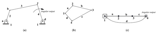
Figure 1.
Representation of a four-bar mechanism. (a) Kinematic structure of a four-bar mechanism; (b) graph representation of a four-bar mechanism; (c) modified graph representation of a four-bar mechanism.
In a four-bar linkage, one angular output is obtained by link-4 as shown in Figure 1a. A modified graph theory is developed to represent a four-bar mechanism according to the following steps:
- Ground link (1) is denoted as a square.
- The output link (4) is denoted as a hollow circle.
- Other links (2, 3) are denoted as vertices.
- The connection between the ground link and output link is denoted by a curved edge (d).
- Other joints are denoted as solid edges (a, b, c) as shown in Figure 1c.
4. Type Synthesis
A four-bar mechanism is initially generated by adding a RRR dyad to the ground link to achieve one angular motion. Then, possibilities for a second output can be detected based on the four-bar linkage. A third output motion, in turn, can be generated from synthesized linkages for two outputs and so on. Therefore, each additional angular output motion involves adding a new RRR dyad to the present mechanism. For computer-aided type synthesis, generation of newer angular outputs can be realized using the modified graph theory. In this paper, two available methods are introduced to connect a new RRR dyad to the existing linkage, namely, parallel connection and series connection methods.
4.1. Parallel Connection Method
In this method, each additional RRR dyad starts from the latest angular output. In other words, the new RRR dyad is connected to the latest angular output and any other link of the original linkage system. That can be achieved by applying the following steps:
- All angular output links should be represented usually at the right of the graph.
- Adding the RRR dyad starts from the last presented angular output link (including two links and three revolute joints).
- The first additional link is located directly above the current output link to represent the ‘newer angular output’. This link is represented as a hollow circle. Therefore, all angular outputs are located in parallel arrangement as shown in Figure 2.
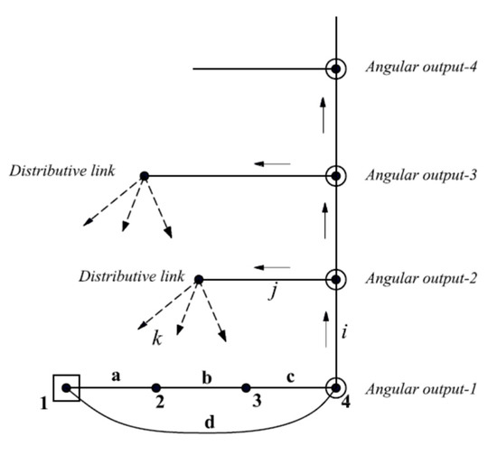 Figure 2. Generation of newer angular outputs using parallel connection.
 - The second additional link is located at the left of the new angular output link. This link is denoted by ‘distributive link’.
- Joints between the previous output, newer output, and distributive links are represented by solid edges (i, j). In other words, angular outputs are presented vertically above each other.
- The last revolute joint (k) has some alternatives to connect the distributive link with other links, excluding the connections that produce rigid sub-chains. These alternatives generate the available topological graphs that can achieve the required number of angular output motions.
4.2. Series Connection Method
In this method, the additional RRR dyad does not start from the latest angular output. It should be connected to all available links of the original linkage system to provide more complicated movements that are required for rehabilitation robots. More angular outputs can be generated from a graph that initially has any number of angular outputs according to the following steps:
- One of the linkage configurations, with a specific number of angular outputs, is selected as illustrated in Figure 3a. The selected configuration has a latest RRR dyad that contains angular output ‘Ni’, link ‘Ci’, which is denoted as ‘cut link’, and revolute joints namely: e, f, and h.
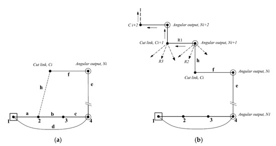 Figure 3. Generation of angular outputs using series connection method. (a) Initial topology with Ni outputs; (b) adding newer angular outputs and cut links.
 - Starting from the cut link, ‘Ci’, joint ‘h’ is deleted and reconnected directly with the newer angular output ‘Ni+1’ which is located directly above the present cut link ‘Ci’ as shown in Figure 3b.
- The second additional link,’Ci+1’, is located at the left of new angular output ‘Ni+1’.
- The joint between the newer output ‘Ni+1’ and its adjacent cut link ‘Ci+1’ is represented by a solid edge ‘R1’. In other words, angular outputs are presented diagonally.
- The remaining two revolute joints (R2, R3) have some alternatives to connect newer output and its adjacent cut link with original links in the linkage graph. That produces some available topological graphs that can achieve the required number of angular output motions, noting that some connections that produce rigid sub-chains should be excluded.
- Additional angular output can be obtained by repeating steps 2–5 so that all angular outputs are located in stepped series arrangement as shown in Figure 3.
4.3. Generation of Two Angular Outputs Using Parallel Connection
Based on the parallel connection method, a mechanism that has two angular output motions can be generated from an initial four-bar mechanism that has one angular output according to the following steps:
- First angular output link is represented at the right of the graph (link-4).
- Adding RRR dyad starts from link-4 (including two additional links: 5, 6).
- Link-5 is located directly above link-4 to represent the second angular output link as shown in Figure 4b.
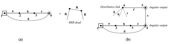
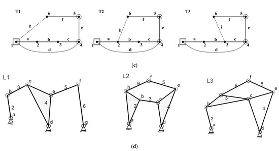 Figure 4. Generation of two angular output motions. (a) Initial linkage having one output; (b) new output ‘link-5’ is added; (c) available topologies having two outputs; (d) corresponding linkage diagrams.
 - The distributive link-6 is located at the left of link-5 as shown in Figure 4b.
- Joints between links (4, 5 and 6) are represented by solid edges (e, f) as shown in Figure 4b.
- The last revolute joint has three alternatives to connect distributive link-6 with other links (joints g, h, i) excluding the connections that produce rigid sub-chains. These alternatives generate three available topological graphs that can achieve two angular output motions as shown in Figure 4c.
- Linkage diagrams, shown in Figure 4d, can be obtained from their corresponding topological graphs as illustrated in Section 4.4.
Therefore, a four-bar linkage that has one angular output can generate three available six-bar linkages with two angular outputs.
4.4. Sketching of Linkage Diagrams
Linkage diagrams can be sketched for all generated topologies. For example, linkage diagram ‘L1’, shown in Figure 4d, can be sketched from its corresponding topology ‘T1’, shown in Figure 4c, according to the following algorithm:
- The original four-bar linkage is sketched containing two fixed pivots, binary links (2, 3, 4), and four revolute joints (a, b, c, d).
- According to topology ‘T1’, link-1 is connected with three links (2, 4, 6). Therefore, a third pivot is added which is connected with a binary link-6 by a revolute joint ‘g’.
- According to topology ‘T1’, link-4 is connected with three links (1, 3, 5). Therefore, link-4 is converted into a ternary link which is connected with a binary link-5 by a revolute joint ‘e’.
- Two binary links (5 and 6) are connected by a revolute joint ‘f’.
Using the same algorithm, all generated topologies can be converted into their corresponding linkage diagrams.
5. Generation of Multiple Angular Outputs
In this section, the proposed methodology is applied to obtain all candidates of mechanical systems that have more than one angular output using both parallel and series connection methods based on a four-bar linkage.
5.1. Generation of Three Angular Outputs Using Parallel Connection
A mechanism that has three angular output motions can be generated from an initial six-bar mechanism that has two angular outputs as illustrated below.
- The existing angular output links are represented at the right of the graph (links 4 and 5) as shown in Figure 5a.
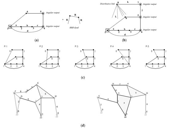 Figure 5. Generation of three angular outputs using parallel connection. (a) Initial linkage having two outputs; (b) new output ‘link 7’ is added; (c) available topologies of three outputs with parallel connection; (d) corresponding linkage diagrams for topologies P2 and P4.
 - Adding the RRR dyad starts from link-5 (including two additional links: 7, 8).
- Link-7 is located directly above link-5 as a third angular output link as shown in Figure 5b.
- The distributive link-8 is located at the left of link-7.
- Joints between links (5, 7 and 8) are represented by solid edges (j, k) as shown in Figure 5b.
- The last revolute joint, l, has five alternatives to connect distributive link-8 with other links in the original linkage graph, excluding the connections that produce rigid sub-chains. These alternatives generate five available eight-bar topological graphs that can achieve three angular output motions as shown in Figure 5c.
- Linkage diagrams can be constructed from their corresponding topological graphs as illustrated in Section 4.4. Some of these linkage diagrams are shown in Figure 5d.
Therefore, each of the six-bar linkages having two angular outputs, shown in Figure 3, can generate five available eight-bar linkages with three angular outputs. Therefore, there are a total of 15 available eight-bar linkages.
5.2. Generation of Three Angular Outputs Using Series Connection
Three angular outputs can be generated from six-bar linkages that have two angular outputs as represented in Figure 6a. The existing RRR dyad contains: angular output ‘5’, cut link ‘6’ and three revolute joints namely: i, j and k. A new angular output can be achieved by adding another RRR dyad using series connection as illustrated in the following steps:
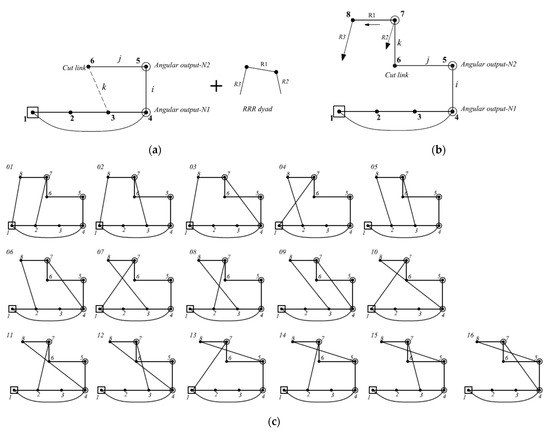
Figure 6.
Generation of three angular outputs using series connection. (a) Initial graphical topology having two outputs; links: 4, 5; (b) new output ‘link-7’ is added; (c) all available topologies of three outputs with series connection.
- Link ‘7’ is added directly above the current cut link ‘6’ to present the newer angular output as a hollow circle as illustrated in Figure 6b.
- Joint ‘k’ is deleted and reconnected directly with the newer angular output ‘7’.
- Link-8 is added at the left of the new angular output as shown in Figure 6b.
- The joint between the newer output ‘7’ and its adjacent cut link ‘8’ is represented by solid edge ‘R1’.
- The remaining two revolute joints (R2, R3) have some alternatives to connect newer output and its adjacent cut link with other links, excluding the connections that produce rigid sub-chains. These alternatives generate the available topological graphs that can achieve the required number of angular output motions as shown in Figure 6c.
- Linkage diagrams can be established from their corresponding topological graphs as illustrated in Section 4.4.
Generally, six-bar linkages having two angular outputs can generate 16 available eight-bar linkages with three angular outputs.
6. Results
The proposed methodology has been used to construct a complete database for planar topologies of mechanisms. These topologies are classified according to the number of available angular outputs. A computer-based type synthesis has been developed using Visual C++. The proposed graphical methodology can easily be extended to obtain planar linkages with any number of angular outputs. All results can be summarized in Table 1.

Table 1.
Generated linkages with up to five angular outputs.
The detailed results are listed below:
- ▪
- A total of three six-bar linkages with up to two angular outputs, illustrated in Figure 3.
- ▪
- A total of 15 eight-bar linkages with up to three angular outputs using parallel connection, illustrated in Figure A1 (given in Appendix A).
- ▪
- A total of 16 ten-bar linkages with up to three angular outputs using series connection, illustrated in Figure 6c.
- ▪
- A total of 105 ten-bar linkages with up to four angular outputs using parallel connection, illustrated in Figure A2 (given in Appendix A).
- ▪
- A total of 18 (out of 576) ten-bar linkages with up to four angular outputs using series connection, illustrated in Figure A3 (given in Appendix A).
- ▪
- A total of 21 (out of 945) twelve-bar linkages with up to five angular outputs using parallel connection, illustrated in Figure A4 (given in Appendix A).
Exoskeleton design procedures depend on some important factors discussed in Section 2. Generally, the exoskeleton designer should preform deep investigation for all of these factors for each case in a detailed study. The presence of a database of exoskeleton linkages, introduced in this work, reduces design procedure time and facilitates the selection process. Moreover, the resulted topologies are classified according to the number of outputs. Therefore, the exoskeleton designer can select a suitable mechanism directly. Then, all mechanism specifications can be detected, such as number of links, joints, number of actuators and their positions, mechanism weight, and fixation technique. Finally, dimension synthesis, simulation, or experimental work should be developed for each individual case to ensure that the selected mechanism can achieve the predetermined trajectory.
Some previous research proposed mechanical linkage systems for some rehabilitation movement. These linkage systems are included in the proposed results. Two examples are listed below to ensure the validity of the proposed database.
6.1. Example-1
For finger rehabilitation motion presented in [21], the desired output of the required mechanism is two end-effectors; one controlling the position and orientation of the first joint and a second controlling the position of the middle joint of the finger as shown in Figure 7d [21]. Therefore, an exoskeleton linkage having two angular outputs are required. These outputs can be obtained by six-, eight-, ten- and twelve-bar mechanisms. The goal is to achieve a natural motion of the finger using a single actuator and a planar mechanism. Although planar six-bar mechanism has a minimum weight, it has a limited trajectory. A planar single DOF eight-bar linkage is proposed to achieve two angular outputs with a more complicated trajectory. Thus, Figure A1 (given in Appendix A), is used to select a proper eight-bar topology such as the topology labeled by ‘15’ shown in Figure 7a. According to Section 4.4, the corresponding linkage diagram can be sketched as illustrated in Figure 7b. This linkage is equivalent to the proposed linkage by [21] as shown in Figure 7c.
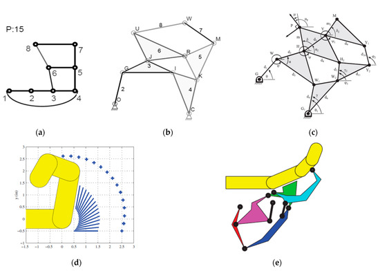
Figure 7.
Using eight-bar linkage as exoskeleton for finger rehabilitation. (a) Selected graph from presented database; (b) corresponding linkage diagram; (c) equivalent exoskeleton linkage introduced by [21]; (d) desired motion for finger introduced by [21]; (e) resulting eight-bar linkage introduced by [21].
6.2. Example-2
For leg rehabilitation motion presented in [20], the angles at the hip and knee joints are illustrated in Figure 8d [20]. As walking is a cyclic motion, a crank-rocker mechanism is preferred for the hip output. A similar angular output is required for the knee joint. Therefore, an exoskeleton linkage having two angular outputs are required for hip and knee joints. These angular outputs can be obtained by six-, eight-, ten- and twelve-bar mechanisms. A planar single DOF eight-bar linkage is proposed to realize the required movement. Thus, Figure 6, generated by series connection, can be used to select a proper eight-bar topology such as the topology labeled by ‘01’ shown in Figure 8a. According to Section 4.4, the corresponding linkage diagram can be sketched as illustrated in Figure 8b. This linkage is equivalent to the proposed linkage by [20] as shown in Figure 8c.
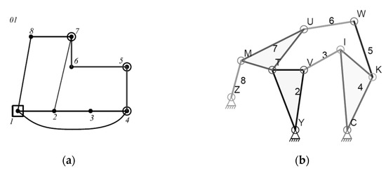
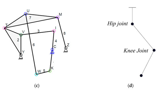
Figure 8.
Using eight-bar linkage as exoskeleton for leg rehabilitation. (a) Selected graph from presented database; (b) corresponding linkage diagram; (c) equivalent exoskeleton linkage; (d) Lower limb joints.
Therefore, the proposed database, illustrated in Table 1, is a reliable tool that can be used to select a suitable exoskeleton linkage or other robotics applications with up to five angular outputs as a type synthesis. Then, a further dimensional synthesis is needed for each design case to detect links and joints orientation as shown in Figure 7e [21] and Figure 8e [20].
However, exoskeleton design procedures can be summarized in the flow chart shown in Figure 9. The main concern of the present study is the type synthesis procedure. The flow chart illustrates how the proposed results can be used during the design process.
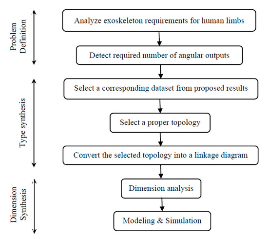
Figure 9.
Exoskeleton design procedures.
7. Conclusions
A new computer-aided graphical methodology has been developed to construct a complete set of exoskeleton mechanical systems used for rehabilitation purposes. The constructed database contains one DOF planar linkages with up to five angular outputs. A modified graphical representation of a four-bar linkage has been presented as an initial system with one angular output. An automatic procedure has been developed to generate multiple angular outputs by adding one or more RRR dyads using Visual C++ with all available connection methods. The proposed methodology produces 3, 15, 105, and 945 mechanical linkages that have two, three, four and five angular outputs, respectively, using a parallel connection method. Additionally, 16 and 576 mechanical linkages that have three and four angular outputs, respectively, have been generated using a series connection method. The presented methodology can be extended to obtain complete sets of planar linkages that have any number of outputs for other robotic applications.
Author Contributions
Conceptualization, M.H., J.W.H., A.H.A. and H.E.; methodology, M.H., J.W.H., A.H.A. and H.E.; software, M.H. and H.E.; validation, M.H., J.W.H. and H.E.; formal analysis, M.H. and H.E.; investigation, M.H., A.H.A., J.W.H. and H.E.; resources, M.H. and H.E.; data curation, M.H. and H.E.; writing—original draft preparation, M.H. and H.E.; writing—review and editing, M.H., A.H.A., J.W.H. and H.E.; visualization, M.H., J.W.H. and H.E.; supervision, M.H. and H.E.; project administration, M.H., J.W.H., A.H.A. and H.E.; funding acquisition, M.H., J.W.H. and H.E. All authors have read and agreed to the published version of the manuscript.
Funding
This work was supported by the Basic Science Research Program through the National Research Foundation of Korea (NRF) grant funded by the Korea Government (MSIT) (No. NRF-2021R1A2B5B02002599).
Institutional Review Board Statement
Not applicable.
Informed Consent Statement
Not applicable.
Data Availability Statement
Not applicable.
Acknowledgments
The authors are grateful to Taif University (Taif, KSA), Mansoura University (Mansoura, Egypt) and Future University in Egypt (Cairo, Egypt) for providing all the required facilities to carry out the present research.
Conflicts of Interest
The authors declared no conflicts of interest.
Appendix A
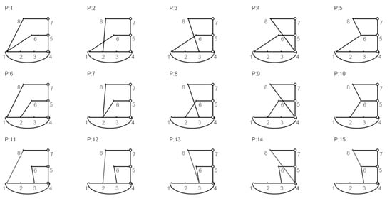
Figure A1.
A complete set of eight-bar linkage topologies with three angular outputs using parallel connection.
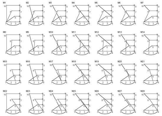
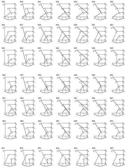
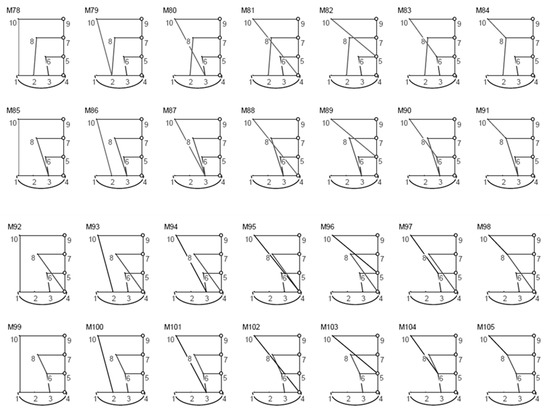
Figure A2.
A complete set of ten-bar linkage topologies with four angular outputs using parallel connection.
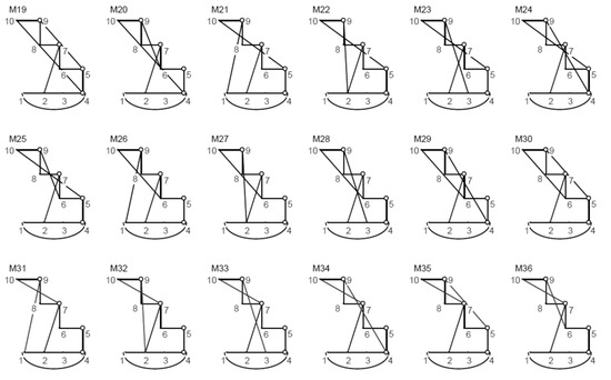
Figure A3.
Some of ten-bar linkage topologies with four angular outputs using series connection.
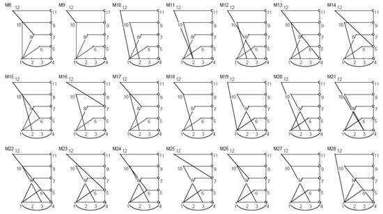
Figure A4.
Some of the twelve-bar linkage topologies with five angular outputs using parallel connection.
References
- Buchsbaum, F.; Freudenstein, F. Synthesis of Kinematic Structure of Geared Kinematic Chains and Other Mechanisms. Mech. Mach. Theory 1970, 5, 357–392. [Google Scholar] [CrossRef]
- Kim, Y.Y.; Jang, G.-W.; Park, J.H.; Hyun, J.S.; Nam, S.J. Automatic Synthesis of a Planar Linkage Mechanism with Revolute Joints by Using Spring-Connected Rigid Block Models. ASME J. Mech. Des. 2007, 129, 930. [Google Scholar] [CrossRef]
- Ding, H.; Yang, W.; Huang, P.; Kecskeméthy, A. Automatic Structural Synthesis of Planar Multiple Joint Kinematic Chains. J. Mech. Des. 2013, 135, 091007. [Google Scholar] [CrossRef]
- Ding, H.; Huang, P.; Yang, W.; Kecskeméthy, A. Automatic generation of the complete set of planar kinematic chains with up to six independent loops and up to 19 links. Mech. Mach. Theory 2016, 96, 75–93. [Google Scholar] [CrossRef]
- Yang, W.; Ding, H.; Lai, X.; Wu, M. Automatic synthesis of planar simple joint mechanisms with up to 19 links. Mech. Mach. Theory 2017, 113, 193–207. [Google Scholar] [CrossRef]
- Olson, D.G.; Erdman, A.G.; Riley, D.R. A Systematic Procedure for Type Synthesis of Mechanisms with Literature Review Literaturbe- Sprechung. Mech. Mach. Theory 1985, 20, 285–295. [Google Scholar] [CrossRef]
- Ding, H.; Hou, F.; Kecskeméthy, A.; Huang, Z. Synthesis of the whole family of planar 1-DOF kinematic chains and creation of their atlas database. Mech. Mach. Theory 2012, 47, 1–15. [Google Scholar] [CrossRef]
- Freudenstein, F.; Dobjansky, L. Some Applications of Graph Theory to the Structural Analysis of Mechanisms. ASME J. Eng. Ind. 1967, 89, 153–158. [Google Scholar] [CrossRef]
- Manolescu, N. A Method Based on Baranov Trusses, and Using Graph Theory to Find the Set of Planar Jointed Kinematic Chains and Mechanisms. Mech. Mach. Theory 1973, 8, 3–22. [Google Scholar] [CrossRef]
- Huang, P.; Ding, H. Structural synthesis of Baranov trusses with up to 13 links. ASME J. Mech. Des. 2019, 141, 072301. [Google Scholar] [CrossRef]
- Han, J.; Shi, S. A novel methodology for determining the singularities of planar linkages based on Assur groups. Mech. Mach. Theory 2020, 147, 103751. [Google Scholar] [CrossRef]
- Huang, P.; Ding, H. Structural synthesis of Assur groups with up to 12 links and creation of their classified databases. Mech. Mach. Theory 2020, 145, 103668. [Google Scholar] [CrossRef]
- Sun, J.; Liu, W.; Chu, J. Dimensional Synthesis of Open Path Generator of Four-Bar Mechanisms Using the Haar Wavelet. ASME J. Mech. Des. 2015, 137, 082303. [Google Scholar] [CrossRef]
- Lin, W.-Y. Optimum Synthesis of Planar Mechanisms for Path Generation Based on a Combined Discrete Fourier Descriptor. ASME J. Mech. Robot. 2015, 7, 041023. [Google Scholar] [CrossRef]
- Kawamura, S.; Ito, K. A New Type of Master Robot for Teleoperation Using a Radial Wire Drive System. In Proceedings of the IEEE/RSJ International Conference on Intelligent Robots and Systems’ 93 (IROS’93), Yokohama, Japan, 26–30 July 1993; pp. 55–60. [Google Scholar]
- Mao, Y.; Agrawal, S.K. Design of a Cable-Driven Arm Exoskeleton (CAREX) for Neural Rehabilitation. IEEE Trans. Robot. 2012, 28, 922–931. [Google Scholar] [CrossRef]
- Zi, B.; Wang, B.; Wang, D. Design and analysis of a novel cable-actuated palletizing robot. Int. J. Adv. Robot. Syst. 2017, 14. [Google Scholar] [CrossRef]
- Robson, N.; Soh, G.S. Geometric design of eight-bar wearable devices based on limb physiological contact task. Mech. Mach. Theory 2016, 100, 358–367. [Google Scholar] [CrossRef] [Green Version]
- Akgun, G.; Kaplanoglu, E.; Cetin, A.E.; Ulkir, O. Mechanical Design of Exoskeleton for Hand Therapeutic Rehabilitation. Quest J. J. Res. Mech. Eng. 2018, 4, 9–17. [Google Scholar]
- Shen, Z.; Allison, G.; Cui, L. An Integrated Type and Dimensional Synthesis Method to Design One Degree-of-Freedom Planar Linkages with Only Revolute Joints for Exoskeletons. ASME J. Mech. Des. 2018, 140, 092302. [Google Scholar] [CrossRef]
- Wolbrecht, E.T.; Reinkensmeyer, D.J.; Perez-Gracia, A. Single degree-of-freedom exoskeleton mechanism design for finger rehabilitation. In Proceedings of the 2011 IEEE International Conference on Rehabilitation Robotics, Zurich, Switzerland, 29 June–1 July 2011. [Google Scholar] [CrossRef] [Green Version]
- Bataller, A.; Cabrera, J.; Clavijo, M.; Castillo, J. Evolutionary Synthesis of Mechanisms Applied to the Design of an Exoskeleton for Finger Rehabilitation. Mech. Mach. Theory 2016, 105, 31–43. [Google Scholar] [CrossRef]
- Foumashi, M.M.; Troncossi, M.; Castelli, V.P. Design of a New Hand Exoskeleton for Rehabilitation of Post-Stroke Patients. CISM Int. Cent. Mech. Sci. 2013, 544, 159–166. [Google Scholar] [CrossRef]
- Cabrera, J.; Nadal, F.; Munoz, J.; Simon, A. Multiobjective Constrained Optimal Synthesis of Planar Mechanisms Using a New Evolutionary Algorithm. Mech. Mach. Theory 2007, 42, 791–806. [Google Scholar] [CrossRef]
- Fontana, M.; Dettori, A.; Salsedo, F.; Bergamasco, M. Mechanical design of a novel Hand Exoskeleton for accurate force displaying. In Proceedings of the 2009 IEEE International Conference on Robotics and Automation, Kobe, Japan, 12–17 May 2009. [Google Scholar] [CrossRef]
- Yihun, Y.; Miklos, R.; Perez-Gracia, A.; Reinkensmeyer, D.J.; Denney, K.; Wolbrecht, E.T. Single Degree-of-Freedom Exoskeleton Mechanism Design for Thumb Rehabilitation. In Proceedings of the 2012 Annual International Conference of the IEEE Engineering in Medicine and Biology Society, San Diego, CA, USA, 28 August–1 September 2012. [Google Scholar] [CrossRef] [Green Version]
- Beigzadeh, B.; Ilami, M.; Najafian, S. Design and development of one degree of freedom upper limb exoskeleton. In Proceedings of the 2015 3rd RSI International Conference on Robotics and Mechatronics (ICROM), Tehran, Iran, 7–9 October 2015. [Google Scholar] [CrossRef]
- Aguirre-Ollinger, G.; Colgate, J.E.; Peshkin, M.A.; Goswami, A. A one-degree-of-freedom assistive exoskeleton with inertia compensation: The effects on the agility of leg swing motion. Proc. Inst. Mech. Eng. Part H J. Eng. Med. 2010, 225, 228–245. [Google Scholar] [CrossRef]
- Baluch, T.H.; Masood, A.; Iqbal, J.; Izhar, U.; Khan, U.S. Kinematic and Dynamic Analysis of a Lower Limb Exoskeleton. World Acad. Sci. Eng. Technol. Int. J. Mech. Mechatron. Eng. 2012, 6, 1945–1949. [Google Scholar]
- Copilusi, C.; Ceccarelli, M.; Dumitru, N.; Carbone, G. Design and Simulation of a Leg Exoskeleton Linkage for a Human Rehabilitation System. In 11th IFToMM International Symposium on Science of Mechanisms and Machines (SYROM’13); Springer: Cham, Switzerland, 2014; pp. 117–125. [Google Scholar] [CrossRef]
- Zhang, C.; Norton, P.R.; Hammonds, T. Optimization of Parameters for Specified Path Generation Using an Atlas of Coupler Curves of Geared Five-Bar Linkages. Mech. Mach. Theory 1984, 19, 459–466. [Google Scholar] [CrossRef]
- Shiakolas, P.; Koladiya, D.; Kebrle, J. On the Optimum Synthesis of Four-Bar Linkages Using Differential Evolution and the Geometric Centroid of Precision Positions. Inverse Probl. Eng. 2002, 10, 485–502. [Google Scholar] [CrossRef]
- Acharyya, S.; Mandal, M. Performance of EAs for Four-Bar Linkage Synthesis. Mech. Mach. Theory 2009, 44, 1784–1794. [Google Scholar] [CrossRef]
- Bulatovic´, R.R.; Dordevic´, S.R. On the Optimum Synthesis of a Four-Bar Linkage Using Differential Evolution and Method of Variable Controlled Deviations. Mech. Mach. Theory 2009, 44, 235–246. [Google Scholar] [CrossRef]
- Kim, J.-W.; Seo, T.; Kim, J. A New Design Methodology for Four- Bar Linkage Mechanisms Based on Derivations of Coupler Curve. Mech. Mach. Theory 2016, 100, 138–154. [Google Scholar] [CrossRef]
- Popescu, I.; Marghitu, D.B. Structural Design of Planar Mechanisms with Dyads. Multibody Syst. Dyn. 2008, 19, 407–425. [Google Scholar] [CrossRef]
- Li, S.; Wang, H.; Dai, J.S. Assur-Group Inferred Structural Synthesis for Planar Mechanisms. ASME J. Mech. Robot. 2015, 7, 041001. [Google Scholar] [CrossRef] [Green Version]
- Tsai, L.W. Mechanism Design: Enumeration of Kinematic Structures According to Function; CRC Press: Boca Raton, FL, USA, 2000. [Google Scholar]
Publisher’s Note: MDPI stays neutral with regard to jurisdictional claims in published maps and institutional affiliations. |
© 2022 by the authors. Licensee MDPI, Basel, Switzerland. This article is an open access article distributed under the terms and conditions of the Creative Commons Attribution (CC BY) license (https://creativecommons.org/licenses/by/4.0/).