Article

Analysis and Optimal Design of a WPT Coupler for Underwater Vehicles Using Non-Dominated Sorting Genetic Algorithm

1
School of Marine Science and Technology, Northwestern Polytechnical University, Xi’an 710072, China
2
Key Laboratory for Unmanned Underwater Vehicle, Northwestern Polytechnical University, Xi’an 710072, China
*
Author to whom correspondence should be addressed.
Appl. Sci. 2022, 12(4), 2015; https://doi.org/10.3390/app12042015
Submission received: 14 January 2022 / Revised: 11 February 2022 / Accepted: 14 February 2022 / Published: 15 February 2022
(This article belongs to the Special Issue Magnetically Coupled Wireless Power Transfer System)

Abstract

:
When the wireless power transfer (WPT) system is installed on the autonomous underwater vehicle (AUV), there is a non-negligible eddy current loss around the coupler. The existence of the ferrite core causes the nonlinear distortion of the magnetic field, which makes the design of the WPT coupler more complicated and difficult. In this paper, the key parameters that affect the performance of the coupler were obtained through calculation and finite element analysis (FEA). Then, the coupler was parametrically modeled in Maxwell, and the Non-dominated Sorting Genetic Algorithm (NSGA-II) was used to optimize its design, considering two objective functions: mutual inductance and equivalent coupler loss impedance (ECLI). Finally, twenty groups of Pareto optimal points were evaluated using the Technique for Ordering Preferences by Similarity to Ideal Solution (TOPSIS) method. Five groups of design points with different weights were screened out. The effectiveness of the optimization process was verified by comparing the optimization results with the initial results.

1. Introduction

As a tool for mankind to explore and develop the ocean, the status of underwater vehicles is becoming more and more prominent. When the battery of the autonomous underwater vehicle (AUV) is about to run out, it needs to be salvaged ashore for charging, which is often troublesome. Wireless power transfer (WPT) technology can solve the energy supply problem of autonomous underwater vehicles [1,2,3,4,5]. When the underwater vehicle needs to be charged, it can go to the pre-arranged underwater wireless charging base station for energy supply without manual operation.
The coupler is a crucial part of the wireless power transfer system, which determines the ability of the WPT system to transmit power [6,7,8]. Seawater contains a lot of sodium ion (Na+) and chloride ion (Cl), while air has few free charges. Therefore, the seawater environment is conducive, and the air environment is non-conducive. The alternating electromagnetic field around the coupler will generate additional eddy current loss, which will reduce the transmission power and efficiency of the system [9,10,11,12]. Therefore, designing a coupler suitable for the underwater environment is particularly important.
The WPT coupler consists of two parts: coils and ferrite cores. Researchers have proposed a variety of excellent coupler structures and practical design methods. In [13], a coil structure suitable for an underwater vehicle with a rotating body structure is proposed, which can achieve stable output power and efficiency when charging autonomous underwater vehicles. In the worst case, 92.1% dc-dc efficiency can be achieved. In [14], a coil size optimization process is proposed for the configuration of DD coils and unipolar coils. The relationship between the size of the secondary coil and the maximum achievable efficiency under two coil topologies is studied. In [15], the design principles of loss optimization and lightweight WPT coils are proposed, using finite element simulation and statistical methods. In [16], an improved alternating current (AC) resistance evaluation method is proposed, the conductive resistance is calculated by frequency-dependent formulas, and the proximity effect resistance is calculated by an improved analytical method. In contrast with the coil part, however, the shape design of the ferrite core has not been extensively studied due to its nonlinear characteristics. In [17], the thickness and shape of the core are optimized to reduce weight, increase coupling factor and reduce loss. In [18,19], the layout of the ferrite cores is studied for optimizing the coupler coefficient between the transmitting and receiving coils. The existence of magnetic cores makes the magnetic field distribution nonlinear and cannot be analyzed by electromagnetic theory. Therefore, many studies on coils and ferrite cores in the past are independent. For the design of the coupler, we took into account both the coils and the magnetic cores. In addition, the coupler is expected to have a large mutual inductance and a small equivalent coupler loss impedance (ECLI). Therefore, the design of the coupler is a multi-objective optimization design problem.
The problem of multi-objective optimization often contains a large number of variables and objective functions. The multi-objective optimization algorithm based on Pareto optimal solution, such as the Non-dominated Sorting Genetic Algorithm (NSGA-II), has been widely applied for its excellent performance [20].
Our work is aimed at the coupler design of an underwater vehicle and comprehensively considers the effects of coil structure and core structure on the coupler performance. The multi-objective optimization design of the coupler is carried out by combining finite element analysis and Non-dominated Sorting Genetic Algorithm II. This paper considers a two-objective optimization strategy of maximizing mutual inductance and minimizing the ECLI of a WPT coupler. Section 2 describes the mechanical structure and circuit structure of the wireless power transfer system. Section 3 analyzes the key parameters that affect the performance of the WPT coupler. Section 4 introduces the optimization process using NSGA-II. Section 5 analyzes the optimization results in detail, and Section 6 summarizes.

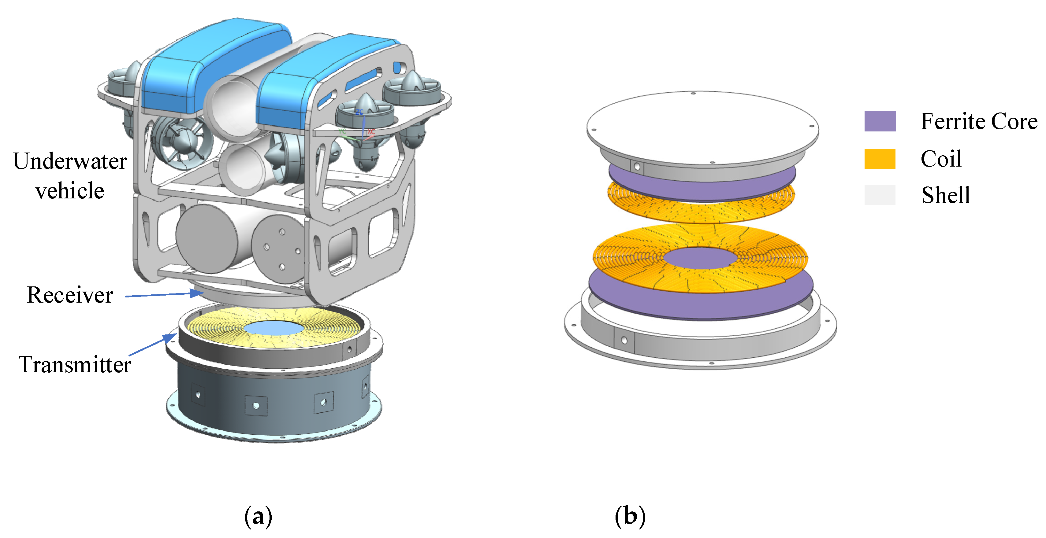
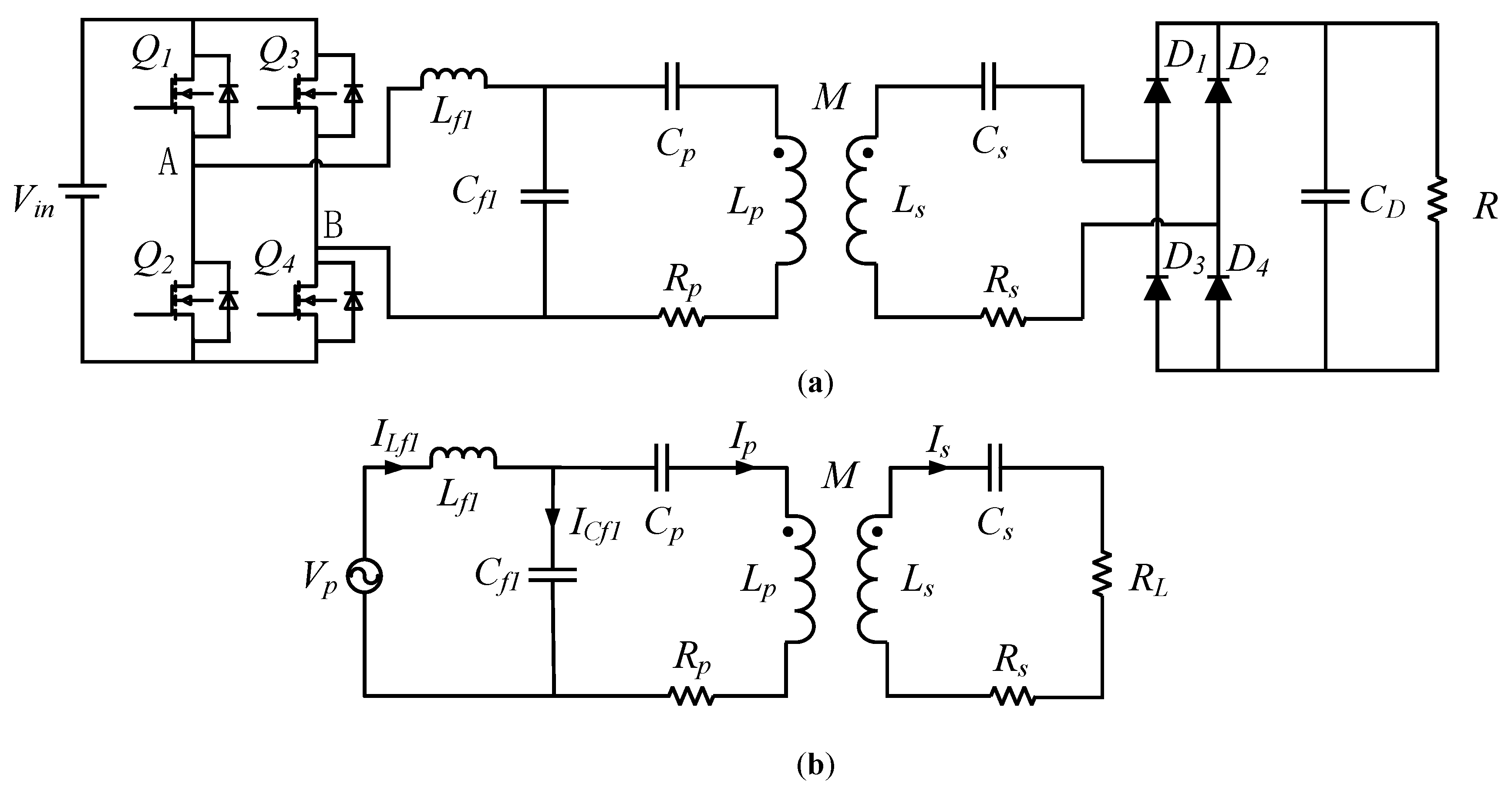
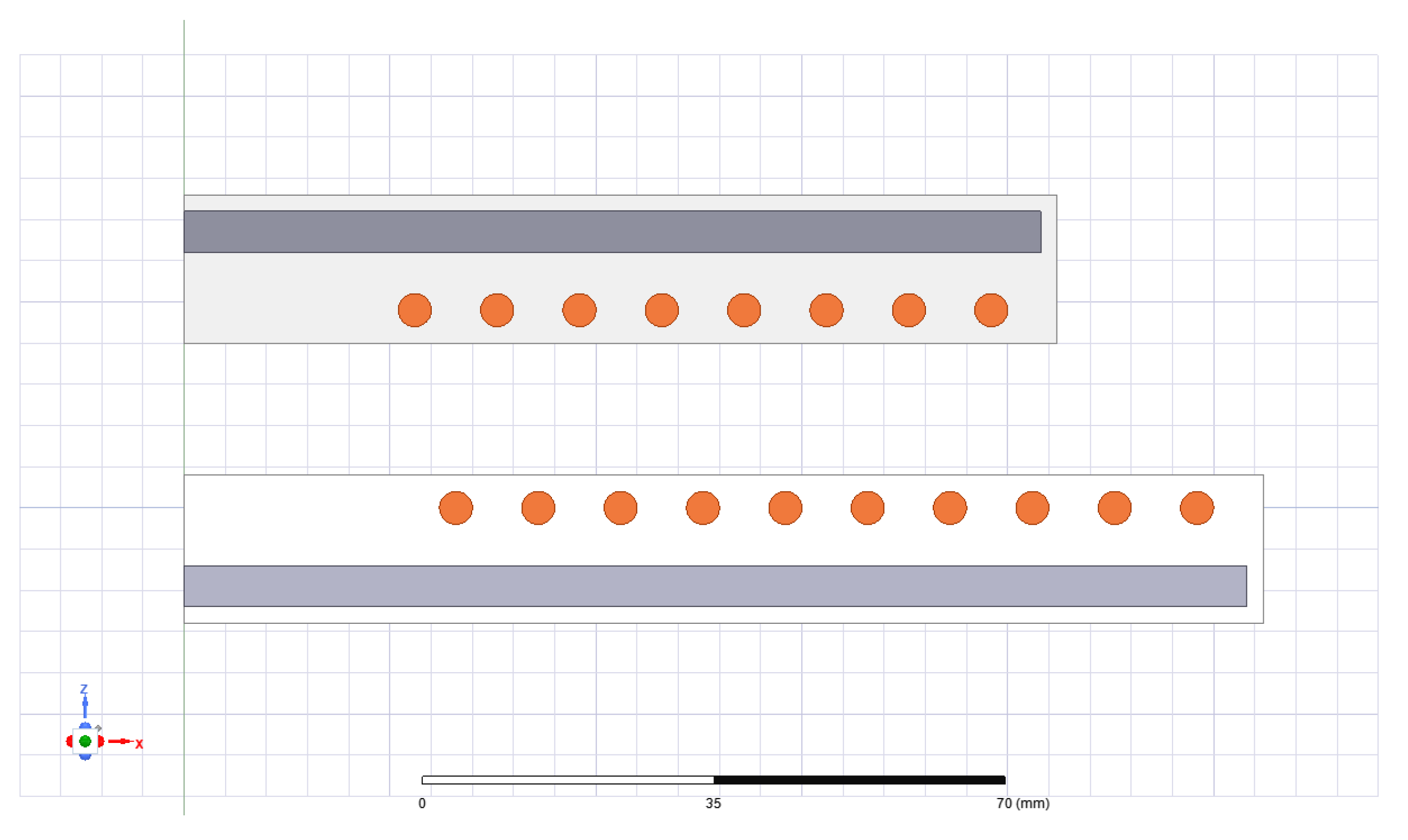
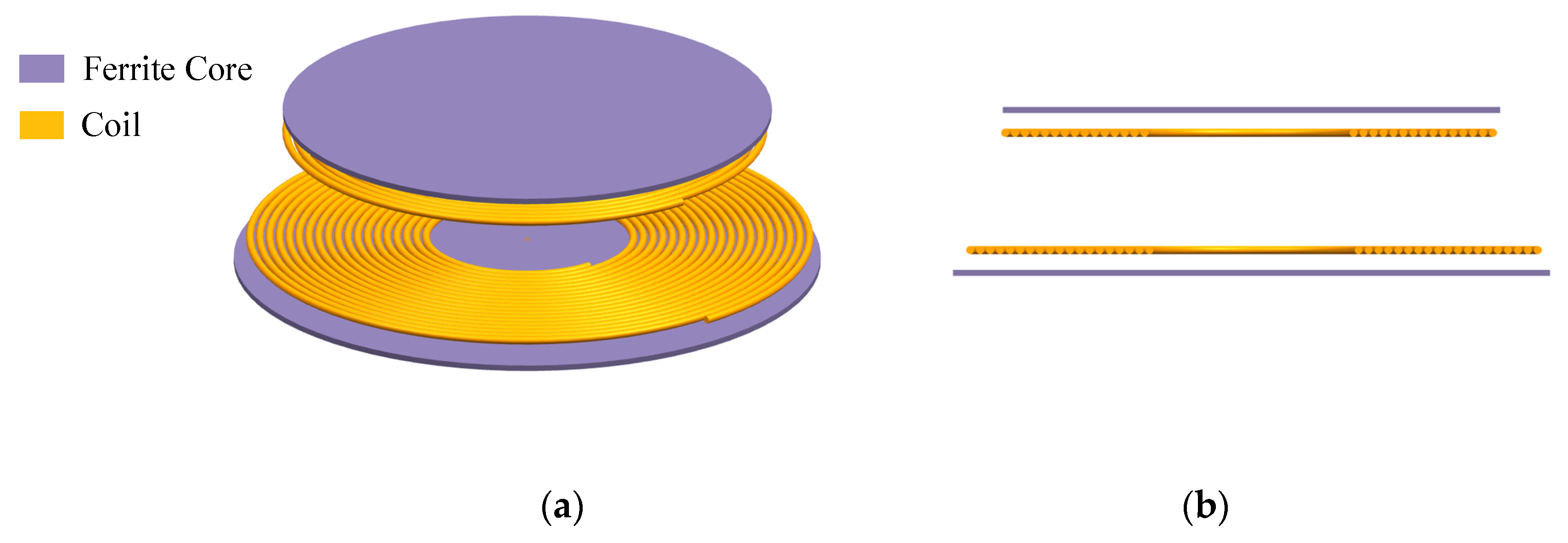
2. Coupler Structure and Circuit Topology

For the frame-type underwater vehicle, Figure 1a shows the overall structure of the WPT system. The transmitter is fixed on the underwater base station, while the receiver is carried by an AUV. Figure 1b shows the WPT coupler structure suitable for framed underwater vehicles, the ferrite core is located at the bottom of the coil, and the coupler shell is made of non-metallic material. The epoxy resin potted inside is used to fix the coil and the iron core and to ensure that the coupler does not leak water.
For wireless power transfer systems, different circuit topologies have different output characteristics. For example, series and series (S-S) compensation topology has constant current output characteristic, inductor–capacitor–capacitor and series (LCC-S) compensation topology has constant voltage output characteristic. Most secondary batteries (Li-ion, LiPo) need a constant-current, constant-voltage charging scheme. In practical applications, the battery can be charged directly using the constant-voltage mode [21]. Considering the limitation of the internal space of AUV, this paper is based on the LCC-S compensation topology. The topology and the equivalent circuit of a wireless transfer system with LCC-S compensation are shown in Figure 2.
In Figure 2, Vin and Vp are DC input and AC output voltages of the inverter, respectively. Q1~Q4 are four power MOSFETs of the inverter. Lf1, Cf1 and Cp are the primary-side compensation inductor and capacitors, respectively. Cs is the secondary-side compensation capacitor. Lp, Ls and M denote the self-inductances and mutual inductance of the coils. D1~D4 are four diodes of the full-bridge rectifier, and CD is the filter capacitor. Rp and Rs are the AC resistance of the coils. R and RL denote the load resistance and the equivalent load resistance after the secondary side compensation, respectively.
According to the circuit equivalent relationship, in Figure 2b, Vp and RL can be expressed as follows:
V p = 2 2 π V i n
R L = 8 π 2 R
According to KVL and KCL equations, the constraint equation of the equivalent circuit in Figure 2b can be established by
{ j ω L f 1 I L f 1 + I C f 1 j ω C f 1 = V p I C f 1 + I p = I L f 1 I C f 1 j ω C f 1 = ( 1 j ω C p + j ω L p + R p ) I p + j ω M I s ( R s + 1 j ω C s + j ω L s + R L ) I s + j ω M I p = 0
where ω is the operating angular frequency. We defined ω0 as the resonant angular frequency when the WPT system works at the resonant frequency, the output power and transmission efficiency can be calculated as
P o u t = I s 2 R L = ω 0 4 M 2 C f 1 2 V p 2 R L ( R s + R L ) 2
η = I s 2 R L V p I L f 1 = ω 0 2 M 2 R L ( R s + R L ) 2 ( R p + R r e f )
where Rref denotes the reflection impedance from the secondary side to the primary side, it can be expressed by the following:
R r e f = ω 0 2 M 2 R s + R L
It can be seen that the output power and efficiency are proportional to the square of the mutual inductance. The loss caused by the resistance of the coupler will reduce the output power and efficiency. Therefore, the mutual inductance and loss of the coupler jointly determine the performance of the coupler.

3. Wireless Power Transfer System in Seawater

The wireless power transfer system has additional eddy current loss in the underwater environment. In addition, the presence of a ferrite core will cause core loss. In this section, the mutual inductance and losses of the coupler are analyzed to obtain the parameters that affect the performance of the coupler, and the equivalent impedance of total loss will be introduced for the subsequent coupler design.

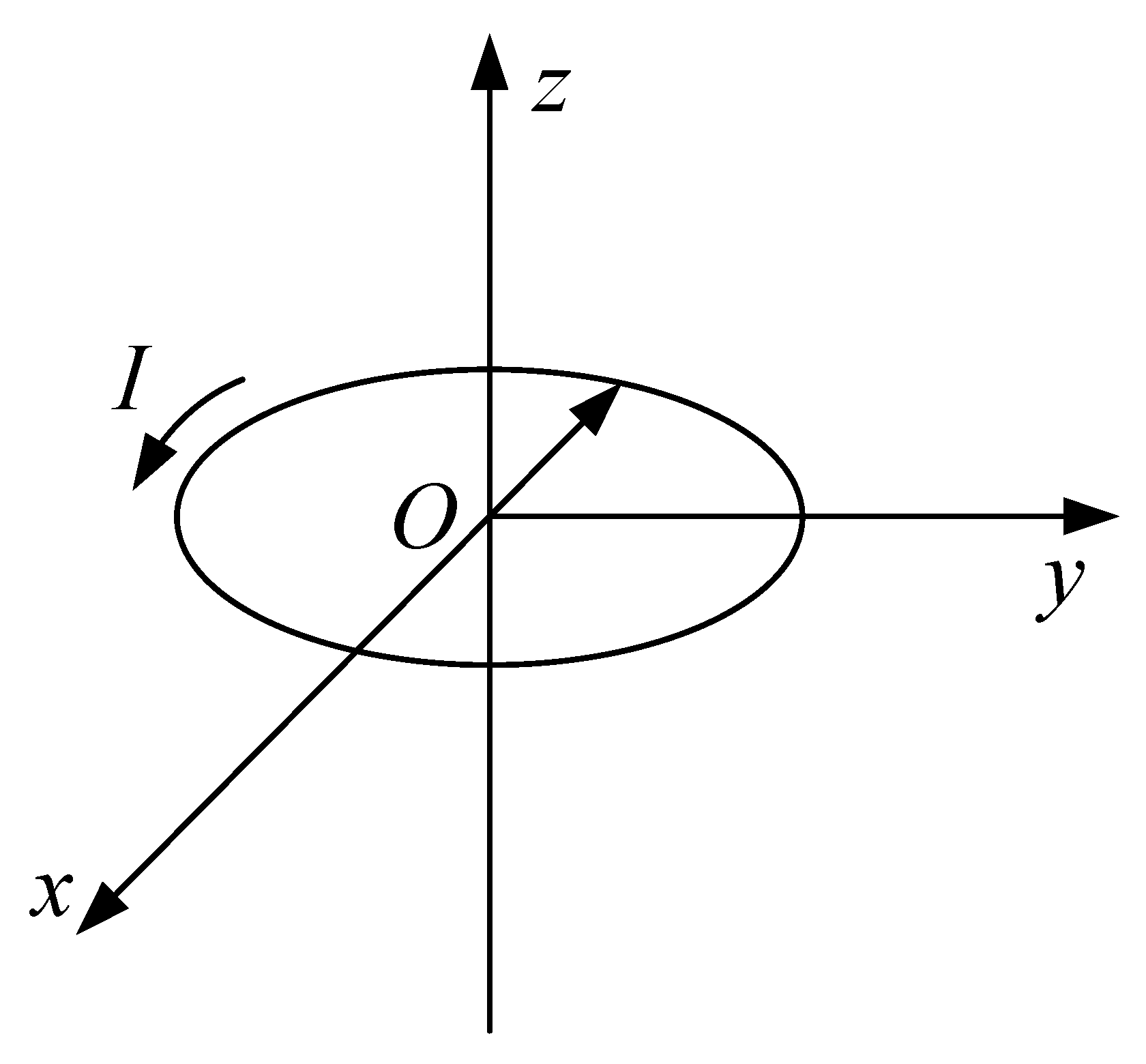
3.1. Electric Field Intensity

For a current-carrying ring in a linear, homogeneous and isotropic medium, the center of the current-carrying ring is at the origin of the coordinate system, and the structure is shown in Figure 3. The electric field around the ring can be obtained by the following [9]:
E ( ρ , z ) = j ω μ ρ 0 I 2 0 λ μ J 1 ( λ ρ 0 ) J 1 ( λ ρ ) e u | z | d λ e ϕ
where μ is the permeability of the medium, ρ0 is the radius of the coil, I is the current value in the coil, λ is a constant, J1 is the Bessel functions of the first kind, eϕ is the circumferential unit vector.
In practical applications, when the wire radius is much smaller than the coil radius, the volume of the wire can be ignored when analyzing the electric field generated by the wire. In general, in a magnetically coupled WPT system, since the distance between each turn of the coil is always smaller than the radius of the coil, we can treat the coil as a set of concentric circles. As shown in Figure 4, the spiral coil is marked with a black dashed line while a string of concentric circles is marked with a solid blue line. When calculating coil parameters, such as the inductance and the electromagnetic field excited by the coil, we use the result calculated by the solid blue lines to approximately replace the calculated result with the black dashed line for simplifying the calculation.
Assume that the turn number of the transmitting coil and the receiving coil is represented by Np and Ns, respectively. We used the principle of vector superposition to calculate the electric field intensity excited by the coils, and they can be expressed as
{ E p = i = 1 i = N p E p i E s = i = 1 i = N s E s i
The electric field intensity generated by the WPT system can be obtained by the superposition of the electric field intensity excited by two coils separately
E T = E p + E s

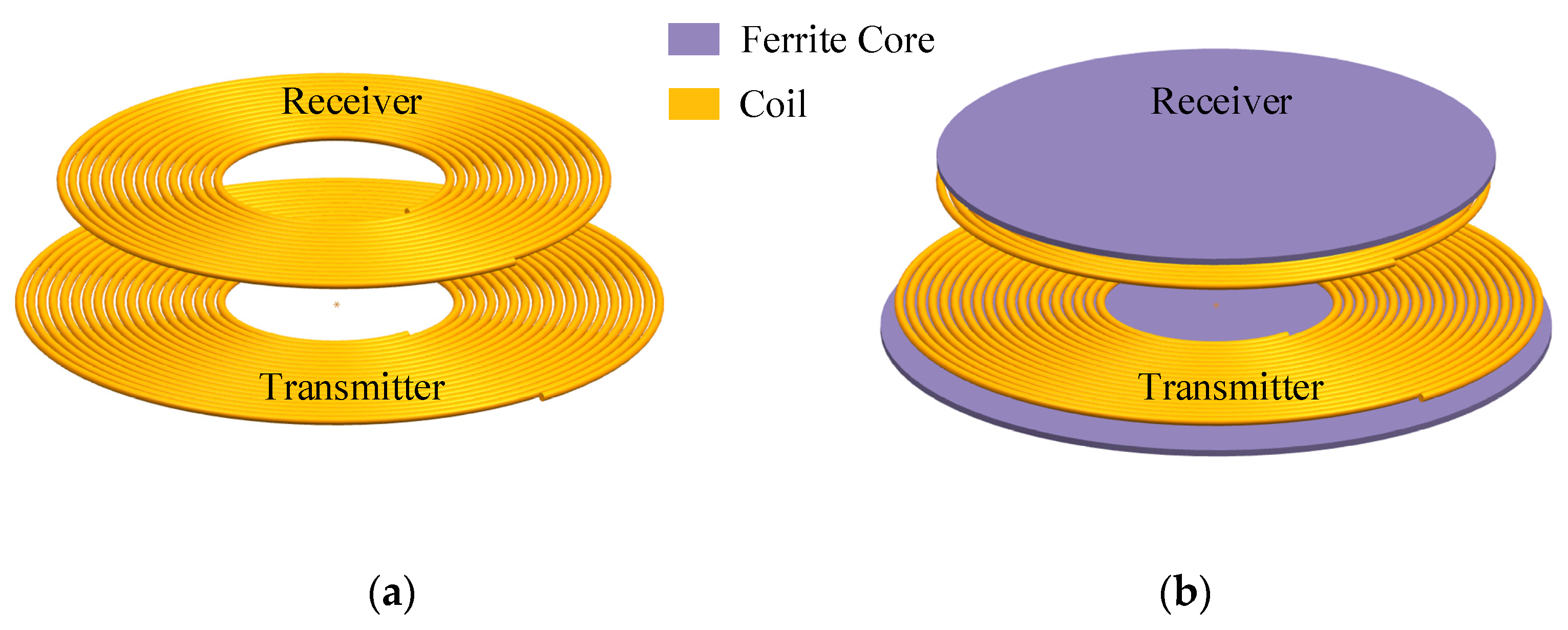
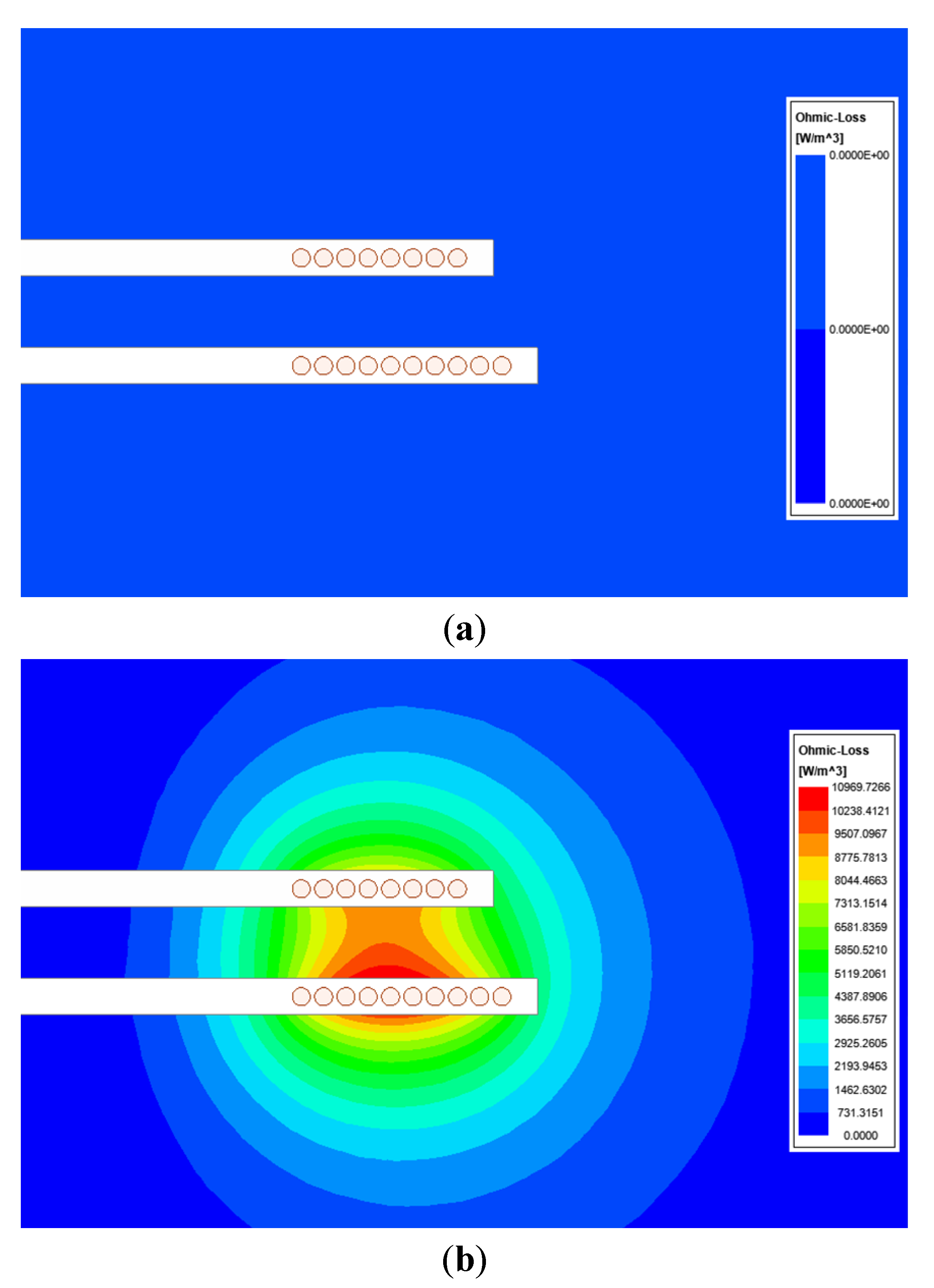
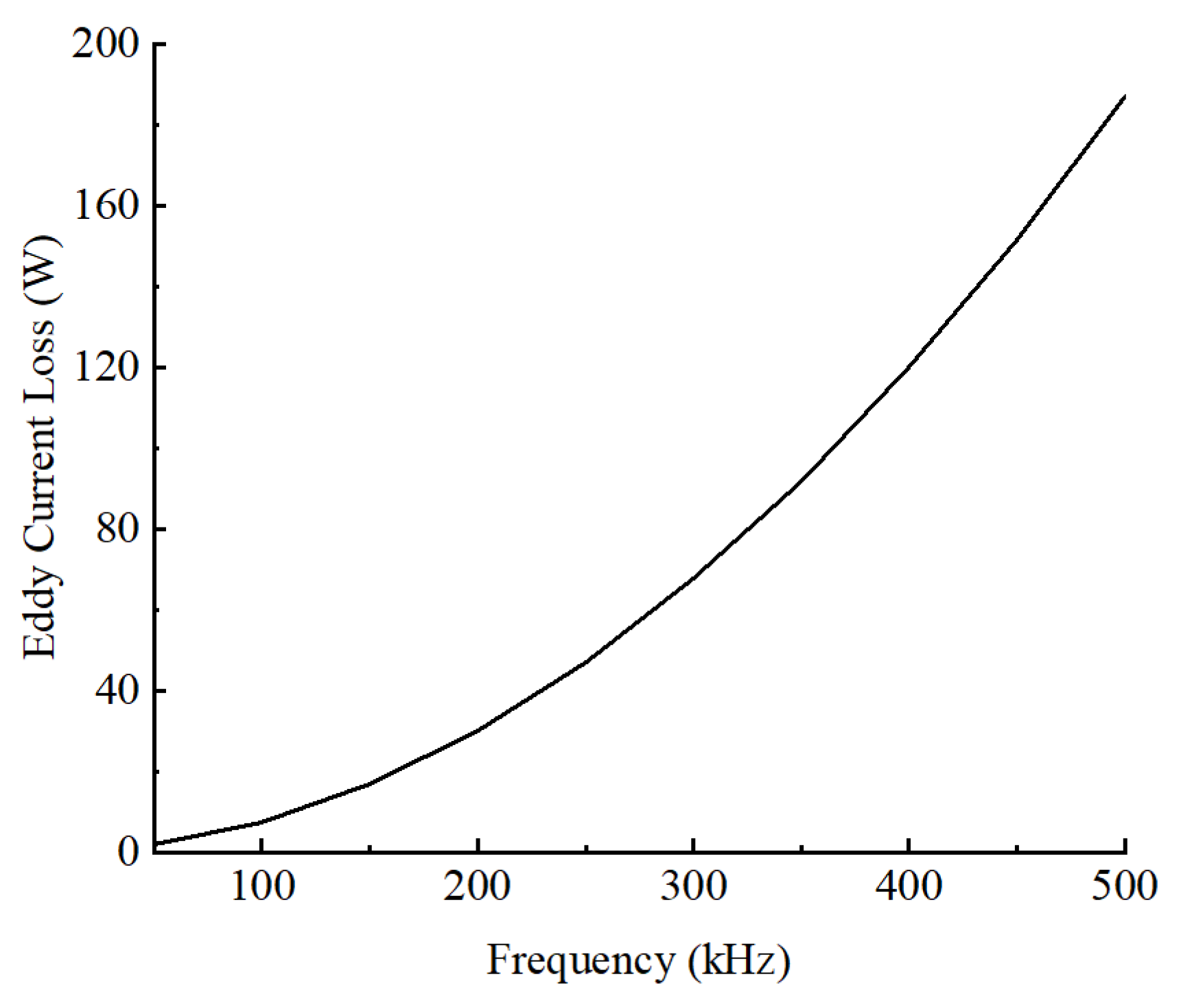
3.2. Power Loss of Coreless Coupler

Figure 5a is a three-dimensional model of a coreless coupler; the transmitter and receiver are only composed of coils. For the wireless power transfer system in the air, the loss of the coreless coupler is mainly caused by the AC resistance of the coils, which is defined as a copper loss. However, when it comes to the application in the seawater environment, due to the conductivity of seawater, the alternating electric field generated by the coils will cause additional power consumption in the seawater, which is eddy current loss. The eddy current loss in the seawater will reduce the ability of the WPT system to transmit power, resulting in a decrease in transmission efficiency.
According to Joule’s law, the eddy current loss can be expressed by
P e d d y = V E T J d V = V σ E T 2 d V
where V is the area where eddy current loss occurs.
From (10), we can see that the eddy current loss is directly related to electrical conductivity. The conductivity of seawater is 3~5 S/m while the air is non-conductive. Therefore, the seawater environment has a non-negligible eddy current loss compared with the air environment. Figure 6 shows the eddy current loss distribution of the external environment of the coupler in air and seawater; there is a noticeable loss in the seawater environment but no loss in an air environment. In Figure 6a, there is no eddy current loss around the coupler since the air does not conduct electricity. In Figure 6b, the alternating magnetic field around the coupler causes eddy current loss in the seawater due to the conductivity of seawater. The red area indicates where the loss is greatest, and the blue area indicates no loss. Therefore, we must consider the eddy current loss when designing the underwater wireless power transfer system.
From (10), we can also see that the eddy current loss is proportional to the square of the modulus of the electric field intensity, while the electric field intensity is greatly affected by the operating frequency, the permeability of the medium the electrical conductivity and the coil structure. We obtained the relationship between the eddy current loss in the seawater environment and the frequency through simulation, as shown in Figure 7. The parameters of the coupler model used in the simulation are: the outer diameter of the transmitter and receiver is 250 mm and 200 mm, respectively. The number of turns of the transmitter and receiver is 10 and 8, the distance between the turns is 2mm, the gap between the transmitter and receiver is 20mm, the coils are wound with litz wire with a diameter of 4mm and the excitation current of the transmitter and receiver is 10 A and 8 A. Figure 7 indicates that the eddy current loss rises as the resonant frequency increases. Therefore, the operating frequency of the magnetically coupled wireless power transfer system used in the seawater environment should not be too large to avoid large eddy current loss.
The change in the coil structure will cause the change in the magnetic field distribution, which will affect the integration result of the eddy current loss. Therefore, the influence of the coil structure should be considered when designing the coupler for wireless charging in the underwater environment, and a structure that can achieve high-efficiency transmission should be selected. We can calculate the electric field intensity in the space by changing the distance between each turn of the coils, then obtain the eddy current loss of the WPT system. However, adjusting the distance between each turn of the coils not only affects the distribution of the magnetic field in the space but also affects the self-inductance and mutual inductance of the coils. In addition, due to the skin effect and proximity effect, the change in the distance between the turns will also cause the change in the coils’ AC impedance. Therefore, on the basis of the previous simulation model, we have studied the influence of distance change in power loss and mutual inductance at 200 kHz operating frequency. Figure 8 shows the simulation results. From Figure 8a, we can see that as the distance increases, the copper loss of the coils and the eddy current loss in the seawater gradually decrease. What we expect is that the copper loss and eddy current loss are as small as possible. From Figure 8b, we can obtain the changing trend of the mutual inductance between the transmitter and receiver; the mutual inductance decreases with the increase in the distance. In wireless power transfer, we hoped that the mutual inductance between the transmitter and receiver was as large as possible so that greater transmission power could be achieved, as expressed in Equation (4). However, the requirements of power loss and mutual inductance on the changing trend of the distance between the turns are opposite. In order to reduce the loss, the distance needs to be increased, but this will cause the mutual inductance between the transmitter and receiver to decrease. Therefore, when designing the coils, how to reduce the power loss as much as possible while satisfying the mutual inductance is a problem worthy of being considered.

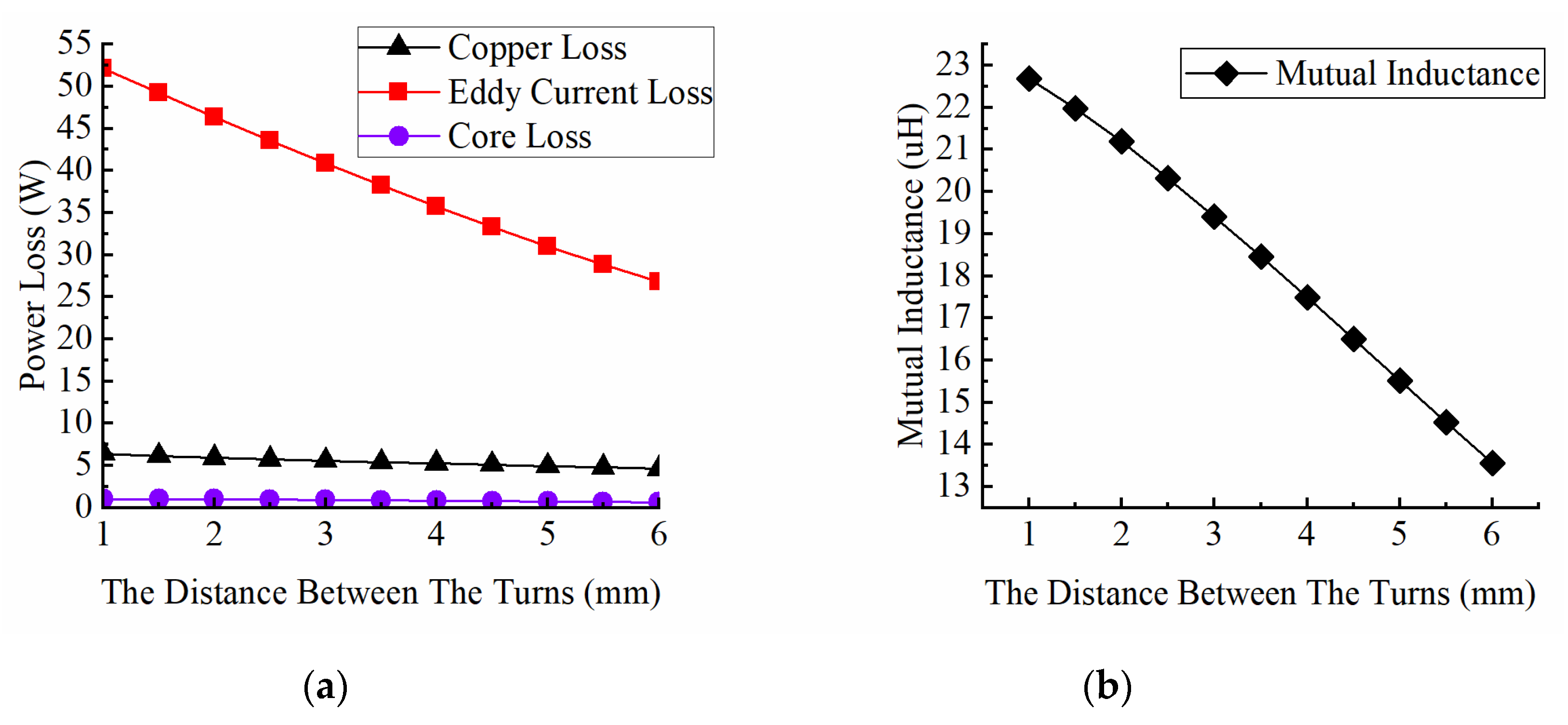
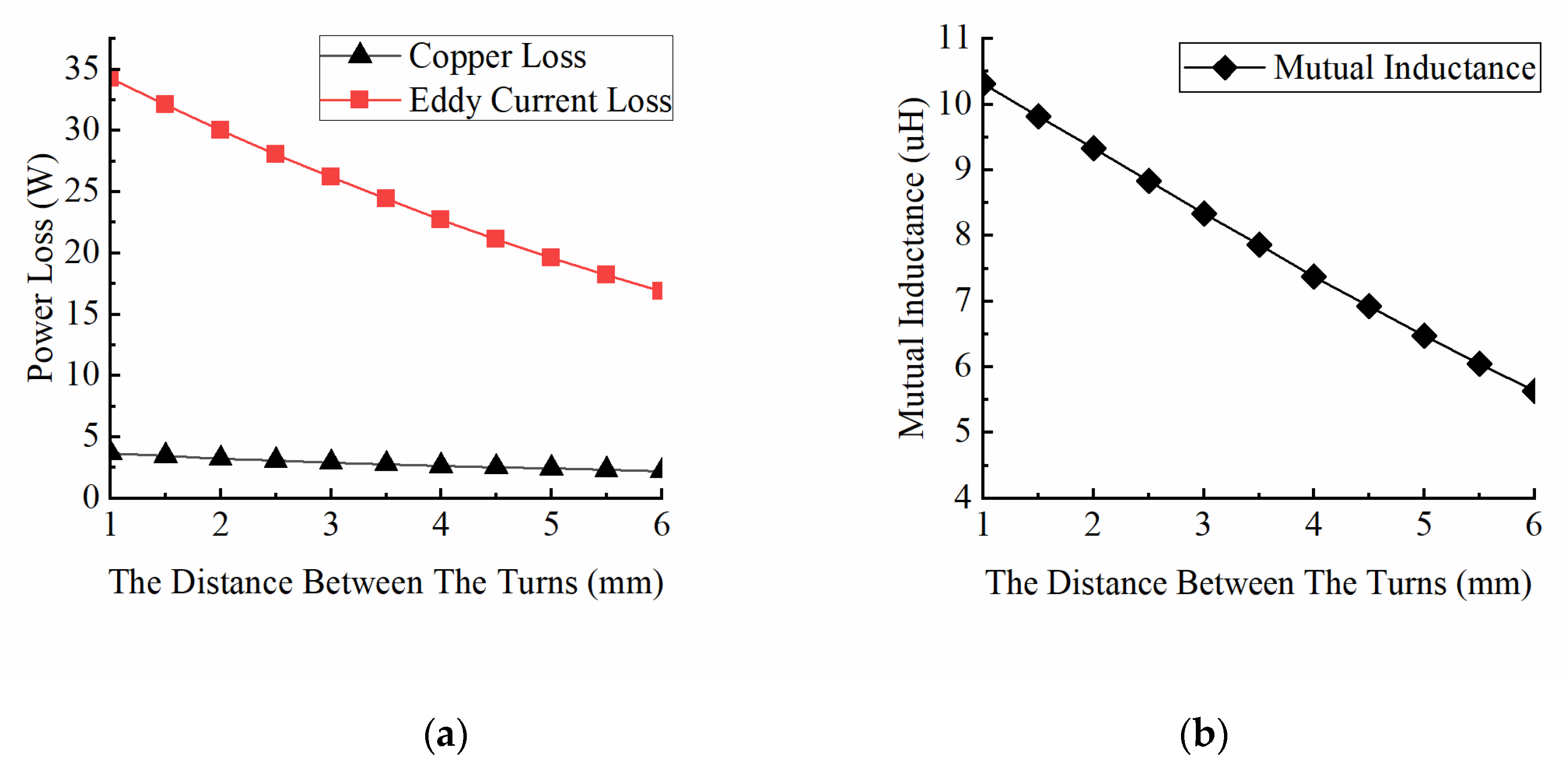
3.3. Power Loss of Coupler with Ferrite Core

In order to increase the mutual inductance between the transmitter and receiver and shield the stray electromagnetic fields, we usually add ferrite cores with high permeability to the bottom of the coils, as is shown in Figure 5b. However, the presence of ferrite will cause the magnetic field to have a nonlinear distribution, so traditional electromagnetic theory cannot be used for analysis. Most previous studies are based on numerical simulations or empirical equations. In addition, the presence of ferrite cores brings additional power loss, which is defined as core loss and causes the AC impedance of the coil, the eddy current loss of the seawater and the weight of the coupler to increase.
Based on the simulation model in the previous section, we added a circular ferrite core with a thickness of 5 mm and the same diameter as the outer diameter of the coils. The material of the ferrite core is set to high-performance PC95. Figure 9 shows the simulation results of the influence of distance change in power loss and mutual inductance. The simulation results in Figure 8 and Figure 9 have the same changing trend. The slope of the curves in Figure 9 is greater than the curves marked with the same symbol in Figure 8 because of the existence of the ferrite core.
In addition, the size of the ferrite core and the distance between the core and the coil will also affect the transmission performance of the coupler. These parameters will be considered in the subsequent design.

3.4. Equivalent Coupler Loss Impedance (ECLI)

From the above analysis, we know that the total loss of the WPT coupler in the seawater environment is composed of three parts: the copper loss in the coils, the eddy current loss in the seawater and the core loss in the ferrite cores; it can be expressed as
P c o u p l e r = P c o p p e r + P e d d y + P c o r e
where Pcopper is the copper loss of two coils, Peddy is the eddy current loss in the seawater, Pcore is the core loss of ferrite cores.
When the current modulus ratio of the transmitter and receiver is fixed, and the current is not large (in this case, the ferrite core works in the linear region), the total loss produced by the coupler is proportional to the square of the current. In order to express the loss level of the coupler more intuitively, we introduce the concept of the equivalent coupler loss impedance (ECLI):
R c o u p l e r = P c o u p l e r I 2
where I is the equivalent value of Ip and Is, especially when Ip/Is = 1, I = Ip = Is. It can be seen that Pcoupler is proportional to I2, so we can use ECLI to study the loss level of the coupler.

4. Optimization Process Using NSGA-II

Through the previous research, we have obtained the key parameters that affect the performance of the coupler in the wireless power transfer system. In this section, we will model the coupler based on these key parameters and propose a method to optimize the design of the coupler using a Non-dominated Sorting Genetic Algorithm.

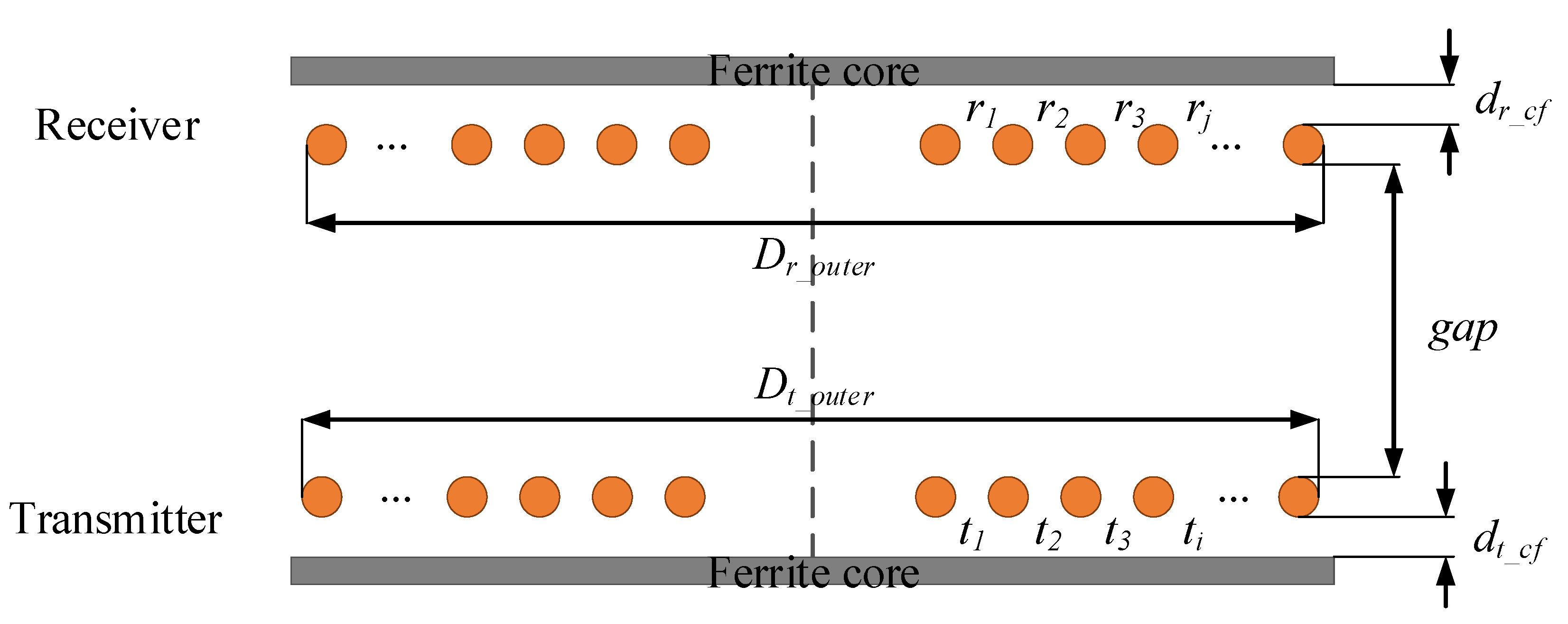
4.1. Parametric Model

The shell of the coupler and the filler material between the coil and the magnetic core in this article are non-metallic, they have no effect on the performance of the coupler, so the shell modeling is not considered. The WPT coupler is composed of two different elements: (1) Transmitter and receiver wound from litz wire and (2) ferrite cores at the bottom of the transmitter and receiver. The WPT coupler is shown in Figure 10.
Since the coupler needs to be installed on the underwater vehicle, the radial size of the coupler is limited by the size of the vehicle, so in this article, we set the outer diameter of the coils and the outer diameter of the magnetic cores in advance, and only consider the distance between the coils and some changes in axial dimensions.
Figure 11 shows the definition of the WPT coupler’s parameters. Dt-outer and Dr-outer are the outer diameters of the transmitter and receiver; t1, t2, t3, ti, r1, r2, r3 and rj are the distance between the turns; dt-cf and dr-cf are the distance between the core and the coil; dt-f and dr-f are the thickness of the ferrite cores; Dt-f and Dr-f are the diameters of the ferrite cores; gap is the distance between the coils. In this paper, the number of turns of the transmitter and receiver is 10 and 8, respectively; a total of 20 design variables are used.

4.2. Numerical Analysis

In this paper, the commercial software ANSYS Maxwell 2021R1 (ANSYS, Pittsburgh, PA, USA) is used to perform parametric modeling and finite element analysis of the WPT coupler. With the ANSYS scripting function provided by Maxwell, one can run the program fully automatically by using MATLAB R2016b (MathWorks, Natick, MA, USA).
In order to reduce the simulation time, we select a 2D EddyCurrent solver in Maxwell and establish a two-dimensional axisymmetric model, as is shown in Figure 12. The coil is made of litz wire model, and the material is copper. The core material is PC95. The gap conductivity inside the coupler is set to 0. The outer area of the coupler is set as seawater, with a conductivity of 4.5 S/m and a relative permittivity of 81. The excitation current of the transmitter and receiver is 10 A and 10 A. The operating frequency is set at 200 kHz.
In this study, the FEA process costs about 9 s with a computer of Intel(R) Core(TM) i7-9700 CPU @ 3.00 GHz for each case which corresponds to one experimental design point.

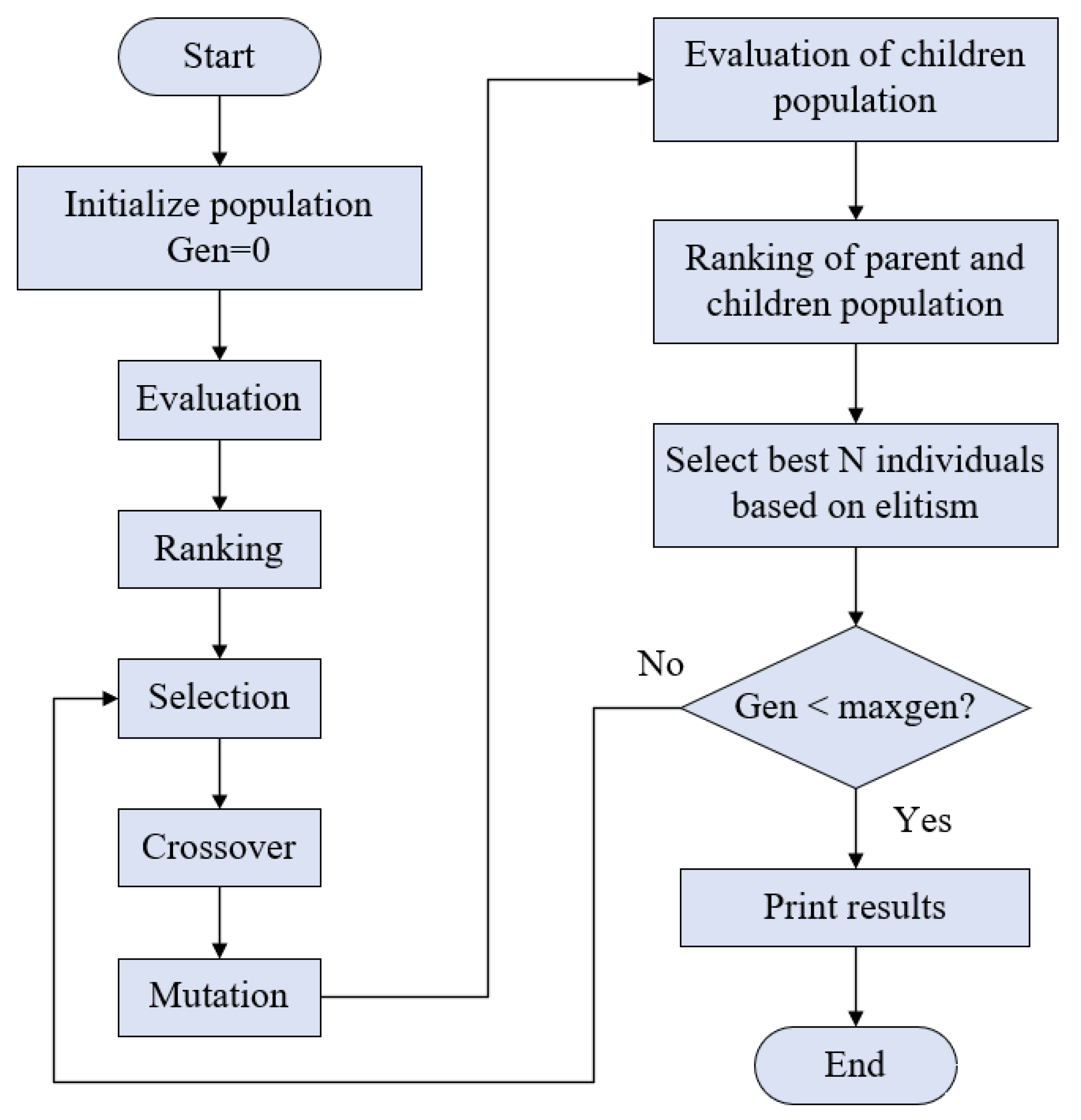
4.3. NSGA-II Optimization Method

The Non-dominated Sorting Genetic Algorithm II (NSGA-II) is a multi-objective optimization algorithm based on Pareto optimal solution [20]. The flowchart of NSGA-II is shown in Figure 13. The steps of NSGA-II are given as follows:
Step 1: Randomly generate the initial population; the size of the population is N;
Step 2: The initial population is sorted by the non-dominated method, followed by selection, crossover and mutation to obtain the first generation offspring population;
Step 3: Merge the new population with the parent population, and perform fast non-dominated sorting on the merged population. Then calculate the crowding degree of the individual, select the appropriate individual according to the non-dominant relationship and the crowding degree of the individual, and form a new parent population;
Step 4: A new population is obtained through the above steps, and the above steps are repeated until the termination condition of the algorithm is satisfied.

4.4. TOPSIS Method

The Technique for Order Preference by Similarity to an Ideal Solution (TOPSIS) method is a commonly used evaluation method in multi-objective decision-making. This method can make full use of the information in the original data and accurately reflect the closeness of each group of results to the ideal result [22]. The method includes the following steps:
Step 1: In order to calculate the normalized decision matrix, we need to assign weights to each objective function; Wj is the weight of the j-th objective function. All weights satisfy the following equation:
j = 1 m W j = 1
Step 2: Normalize objective functions Fij; Fij represents the i-th optimal point of the j-th objective function.
p i j = F i j i = 1 τ F i j 2   f o r   i = 1 , 2 , , τ ; j = 1 , 2 , , m
Step 3: Perform weighted normalization on the normalized function matrix:
q i j = W j × p i j
Step 4: Compute worst and best vectors:
F = ( min ( q 11 , q 21 , , q τ 1 ) , min ( q 12 , q 22 , , q τ 2 ) , , min ( q 1 m , q 2 m , , q τ m ) )
F + = ( max ( q 11 , q 21 , , q τ 1 ) , max ( q 12 , q 22 , , q τ 2 ) , , max ( q 1 m , q 2 m , , q τ m ) )
Step 5: Calculate the Euclidean distance between each evaluation object and the worst vector and the optimal vector:
D i = j = 1 m ( q i j F j ) 2   f o r   i = 1 , 2 , , τ ; j = 1 , 2 , , m
D i + = j = 1 m ( q i j F j + ) 2   f o r   i = 1 , 2 , , τ ; j = 1 , 2 , , m
Step 6: Calculate the relative closeness of each target:
D i = D i D i + + D i , 0 D i 1
Step 7: Sort Di to select the optimal objective function; the maximum value of Di will be chosen.

5. Optimization of WPT Coupler

5.1. Multi-Objective Problem

Regarding the optimization design problem of the WPT coupler in this paper, increasing the distance between the turns reduces the ECLI, but this leads to a reduction in mutual inductance. Therefore, reducing ECLI and increasing mutual inductance have contradictory requirements for the coil distance; they cannot obtain high performance simultaneously. In addition, the thickness of the magnetic core and the distance between the ferrite core and the coil also affect the performance of the coupler.
The outer diameter of the transmitter and receiver depends on the size of the coupler, which is 250 mm and 200 mm, respectively. In order to simplify the problem, the number of turns on the primary side and secondary side is limited to 10 and 8, respectively. The distance between each turn of the coil is not equal; it depends on the choice of algorithm. The multi-objective optimization problem can be expressed as:
{ min   F ( X ) = [ M , E C L I ] s . t .   1 t i 6 ,   i = 1 , 2 , 3 9 1 r j 6 ,   j = 1 , 2 , 3 7 1 d t _ c f 5 1 d r _ c f 5 1 d t _ f 5 1 d r _ f 5
where M is the mutual inductance between the transmitter and receiver.

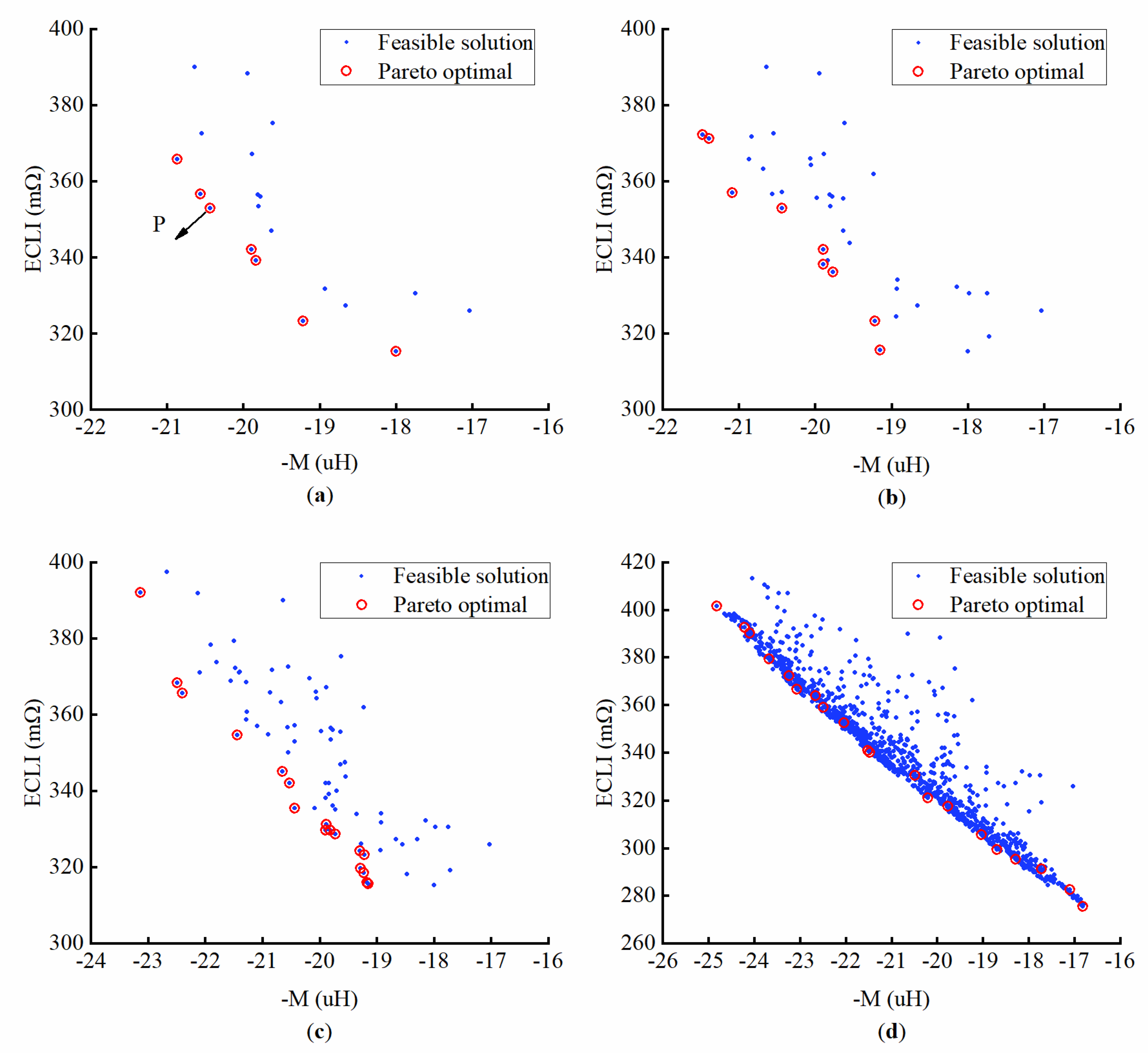
5.2. Results and Discussion

In the multi-objective optimization process using NSGA-II, the population size is 20 and the number of generations is 60. Through the multi-objective optimization process, 20 Pareto optimal design points are obtained. The corresponding objective functions value are shown in Table 1.
Figure 14 shows the convergence process of the Pareto front. Since the algorithm optimizes in the direction of the minimum by default, a negative sign is added in front of the mutual inductance. As the number of iterations increases, the Pareto front gradually converges. After 60 iterations, the Pareto front hardly changes, and the iteration stops.
Table 2 lists the design points with different weights selected from the Pareto optimal points using the TOPSIS method, where W1 is the weight of mutual inductance, W2 is the weight of ECLI. The optimal design point A stands for the maximum mutual inductance ratio, while the optimal design point E stands for the minimal ECLI, respectively. The results of design point A and design point E can also be obtained by the single-objective optimization method. The reason that design points A and B are the same is the limited number of Pareto optimal solutions and the randomness of NSGA-II. There are two ways to obtain different design points; the first is to increase the number of Pareto optimal solutions, which can make the design points more evenly distributed. Another method is to redo the optimization process. Due to the randomness of the genetic algorithm, it may obtain different results if it is re-iterated.
The mutual inductance and ECLI gradually decrease from design points A to E because the weight of mutual inductance is decreasing, and the weight of ECLI is increasing. In practical applications, it may not be necessary to maximize the mutual inductance or minimize the ECLI, and we can adjust the weights W1 and W2 according to our actual needs.
Compared with the initial point P, the mutual inductance value of design point B has increased by 21.45%, while the ECLI has increased by less than 50 mΩ, which has little effect on power loss. From (4) and (5), we can see that the mutual inductance directly affects output power and efficiency, so the performance of the coupler at design point B is significantly better than that at design point P. Therefore, the process of multi-objective optimization is effective.

6. Conclusions

In this paper, the key parameters that affect the performance of the WPT coupler are obtained through calculation and simulation, and an effective coupler optimization design method is proposed. This method integrated parametric modeling finite element analysis through Maxwell, NSGA-II through MATLAB. Multi-objective optimization consists of two objectives and twenty variables. After sixty iterations, twenty groups of Pareto optimal points are obtained, and five groups of design points with different weights are screened out using the TOPSIS method. The results show that the optimization method is effective and suitable for WPT coupler design.

Author Contributions

Conceptualization, B.L. and Z.M.; methodology, B.L., Z.M., K.Z. and P.L.; software, B.L.; validation, B.L., Z.M., K.Z. and P.L.; formal analysis, B.L.; investigation, B.L.; resources, B.L.; data curation, B.L.; writing—original draft preparation, B.L.; writing—review and editing, B.L., Z.M., K.Z. and P.L.; visualization, B.L. and P.L.; supervision, Z.M., K.Z. and P.L.; project administration Z.M., K.Z. and P.L.; funding acquisition, Z.M. All authors have read and agreed to the published version of the manuscript.

Funding

This research was funded by the National Natural Science Foundation of China, grant number 52171338.

Institutional Review Board Statement

Not applicable.

Informed Consent Statement

Not applicable.

Data Availability Statement

Not applicable.

Conflicts of Interest

The authors declare no conflict of interest.

References

  1. Feezor, M.D.; Sorrell, F.Y.; Blankinship, P.R. An interface system for autonomous undersea vehicles. IEEE J. Ocean. Eng. 2001, 26, 522–525. [Google Scholar] [CrossRef]
  2. McGinnis, T.; Henze, C.P.; Conroy, K. Inductive Power System for Autonomous Underwater Vehicles. OCEANS 2007, 2007, 1–5. [Google Scholar]
  3. Song, B.; Wang, Y.; Zhang, K.; Mao, Z. Research on wireless power transfer system for Torpedo autonomous underwater vehicles. Adv. Mech. Eng. 2018, 10, 1–8. [Google Scholar] [CrossRef]
  4. Anyapo, C.; Intani, P. Wireless Power Transfer for Autonomous Underwater Vehicle. In Proceedings of the 2020 IEEE PELS Workshop on Emerging Technologies: Wireless Power Transfer (WoW), Seoul, Korea, 15–19 November 2020; pp. 246–249. [Google Scholar]
  5. Teeneti, C.R.; Truscott, T.T.; Beal, D.N.; Pantic, Z. Review of Wireless Charging Systems for Autonomous Underwater Vehicles. IEEE J. Ocean. Eng. 2021, 46, 68–87. [Google Scholar] [CrossRef]
  6. Li, S.; Mi, C.C. Wireless Power Transfer for Electric Vehicle Applications. IEEE J. Emerg. Sel. Top. Power Electron. 2015, 3, 4–17. [Google Scholar]
  7. Deng, J.; Li, W.; Nguyen, T.D.; Li, S.; Mi, C.C. Compact and Efficient Bipolar Coupler for Wireless Power Chargers: Design and Analysis. IEEE Trans. Power Electr. 2015, 30, 6130–6140. [Google Scholar] [CrossRef]
  8. Miller, J.M.; Daga, A. Elements of Wireless Power Transfer Essential to High Power Charging of Heavy Duty Vehicles. IEEE Trans. Transp. Electrif. 2015, 1, 26–39. [Google Scholar] [CrossRef]
  9. Zhang, K.; Ma, Y.; Yan, Z.; Di, Z.; Song, B.; Hu, A.P. Eddy Current Loss and Detuning Effect of Seawater on Wireless Power Transfer. IEEE J. Emerg. Sel. Top. Power Electron. 2020, 8, 909–917. [Google Scholar] [CrossRef]
  10. Cheng, Z.; Lei, Y.; Song, K.; Zhu, C. Design and Loss Analysis of Loosely Coupled Transformer for an Underwater High-Power Inductive Power Transfer System. IEEE Trans. Magn. 2015, 51, 1–10. [Google Scholar]
  11. Zhang, K.; Zhu, Z.; Song, B.; Xu, D. A power distribution model of magnetic resonance WPT system in seawater. In Proceedings of the 2016 IEEE 2nd Annual Southern Power Electronics Conference (SPEC), Auckland, New Zealand, 5–8 December 2016; pp. 1–4. [Google Scholar]
  12. Yan, Z.; Zhang, Y.; Kan, T.; Lu, F.; Zhang, K.; Song, B.; Mi, C.C. Frequency Optimization of a Loosely Coupled Underwater Wireless Power Transfer System Considering Eddy Current Loss. IEEE Trans. Ind. Electron. 2019, 66, 3468–3476. [Google Scholar] [CrossRef]
  13. Yan, Z.; Song, B.; Zhang, Y.; Zhang, K.; Mao, Z.; Hu, Y. A Rotation-Free Wireless Power Transfer System With Stable Output Power and Efficiency for Autonomous Underwater Vehicles. IEEE Trans. Power Electr. 2019, 34, 4005–4008. [Google Scholar] [CrossRef]
  14. Zhang, W.; White, J.C.; Abraham, A.M.; Mi, C.C. Loosely Coupled Transformer Structure and Interoperability Study for EV Wireless Charging Systems. IEEE Trans. Power Electr. 2015, 30, 6356–6367. [Google Scholar] [CrossRef]
  15. Prengel, S.; Helwig, M.; Modler, N. Lightweight coil for efficient wireless power transfer: Optimization of weight and efficiency for WPT coils. In Proceedings of the 2014 IEEE Wireless Power Transfer Conference, Jeju, Korea, 8–9 May 2014; pp. 96–99. [Google Scholar]
  16. Wei, G.; Jin, X.; Wang, C.; Feng, J.; Zhu, C.; Matveevich, M.I. An Automatic Coil Design Method With Modified AC Resistance Evaluation for Achieving Maximum Coil–Coil Efficiency in WPT Systems. IEEE Trans. Power Electr. 2020, 35, 6114–6126. [Google Scholar] [CrossRef]
  17. Shijo, T.; Ogawa, K.; Obayashi, S. Optimization of thickness and shape of core block in resonator for 7 kW-class wireless power transfer system for PHEV/EV charging. In Proceedings of the 2015 IEEE Energy Conversion Congress and Exposition (ECCE), Montreal, QC, Canada, 20–24 September 2015; pp. 3099–3102. [Google Scholar]
  18. Budhia, M.; Covic, G.A.; Boys, J.T. Design and Optimization of Circular Magnetic Structures for Lumped Inductive Power Transfer Systems. IEEE Trans. Power Electr. 2011, 26, 3096–3108. [Google Scholar] [CrossRef]
  19. Rituraj, G.; Kumar, P. A New Magnetic Structure of Unipolar Rectangular Coils in WPT Systems to Minimize the Ferrite Volume While Maintaining Maximum Coupling. IEEE Trans. Circuits Syst. II-Express Briefs 2021, 68, 2072–2076. [Google Scholar] [CrossRef]
  20. Deb, K.; Pratap, A.; Agarwal, S.; Meyarivan, T. A fast and elitist multiobjective genetic algorithm: NSGA-II. IEEE Trans. Evolut. Comput. 2002, 6, 182–197. [Google Scholar] [CrossRef] [Green Version]
  21. Ramezani, A.; Farhangi, S.; Iman-Eini, H.; Farhangi, B.; Rahimi, R.; Moradi, G.R. Optimized LCC-Series Compensated Resonant Network for Stationary Wireless EV Chargers. IEEE Trans. Ind. Electron. 2019, 66, 2756–2765. [Google Scholar] [CrossRef]
  22. Opricovic, S.; Tzeng, G. Compromise solution by MCDM methods: A comparative analysis of VIKOR and TOPSIS. Eur. J. Oper. Res. 2004, 156, 445–455. [Google Scholar] [CrossRef]
Figure 1. Underwater vehicle with wireless charging system. (a) Overall structure. (b) WPT coupler structure.
Applsci 12 02015 g001
Figure 2. The LCC-S-compensated WPT system. (a) Topology. (b) Equivalent circuit.
Applsci 12 02015 g002
Figure 3. The current-carrying ring is in the same homogeneous medium.
Applsci 12 02015 g003
Figure 4. Approximately treat the plane spiral as concentric circles.
Applsci 12 02015 g004
Figure 5. Three-dimensional model of coupler. (a) Coreless coupler. (b) Coupler with ferrite core.
Applsci 12 02015 g005
Figure 6. Eddy current loss distribution. (a) Air environment. (b) Seawater environment.
Applsci 12 02015 g006
Figure 7. Simulation results of power loss vary with frequency.
Applsci 12 02015 g007
Figure 8. Simulation results of power loss and mutual inductance of the coreless structure vary with the distance between the turns. (a) Power loss. (b) Mutual inductance.
Applsci 12 02015 g008
Figure 9. Simulation results of power loss and mutual inductance of the ferrite core structure vary with the distance between the turns. (a) Power loss. (b) Mutual inductance.
Applsci 12 02015 g009
Figure 10. Coupler with ferrite core. (a) Three-dimensional view. (b) Cross-section.
Applsci 12 02015 g010
Figure 11. Definition of WPT coupler.
Applsci 12 02015 g011
Figure 12. Two-dimensional axisymmetric model in Maxwell.
Applsci 12 02015 g012
Figure 13. Flowchart of NSGA-II.
Applsci 12 02015 g013
Figure 14. Pareto front: (a) The 1st iteration. (b) The 2nd iteration. (c) The 4th iteration. (d) The 60th iteration.
Applsci 12 02015 g014
Table 1. Pareto optimal design points.
M/uHECLI/mΩ
124.10749390.15168
222.49816359.09016
323.2414372.4909
420.48618330.66909
520.21399321.03443
622.04907352.67751
723.67923379.34
819.04261305.60054
917.10243282.64609
1016.82043275.73258
1118.28402295.34013
1221.47508340.11445
1321.52286340.87653
1417.7255291.37137
1524.82117401.69557
1624.21178392.58677
1719.76503317.67936
1822.67059364.00505
1918.69793299.45943
2023.07243366.70417
Table 2. Sets of optimization results.
W1W2M/uHECLI/mΩ
A1024.82117401.69557
B0.750.2524.82117401.69557
C0.50.516.82043275.73258
D0.250.7516.82043275.73258
E0116.82043275.73258
Initial point P20.43746353.01086
Publisher’s Note: MDPI stays neutral with regard to jurisdictional claims in published maps and institutional affiliations.

