Article

Verification and Comparison of Direct Calculation Method for the Analysis of Support–Ground Interaction of a Circular Tunnel Excavation

1
Department of Civil Engineering, Chung Hua University, No. 707, Sec. 2, Wufu Rd., Hsinchu 30012, Taiwan
2
Department of Civil and Disaster Prevention Engineering, National United University, No. 2 Lienda Rd., Miaoli 36003, Taiwan
*
Author to whom correspondence should be addressed.
Appl. Sci. 2022, 12(4), 1929; https://doi.org/10.3390/app12041929
Submission received: 15 January 2022 / Revised: 9 February 2022 / Accepted: 11 February 2022 / Published: 12 February 2022
(This article belongs to the Special Issue Advanced Underground Space Technology)

Abstract

:
A direct algorithmic process can deal with the solution of the support–ground interaction in a circular tunnel excavation through the convergence-confinement method (CCM) with the concept of increment. This process is the so-called direct calculation method (DCM) that can find solutions, the mobilized support pressure and the convergence, in the analysis of CCM. To achieve the solution, using two linear equations in the elastic region and Newton’s recursive method to find the roots in the plastic region are proposed and realized by a calculated spreadsheet. The validity of the algorithmic process for the analytical solutions was investigated and verified by the finite element computation, and compared with the published results, Rocksupport (2004), Oreste (2009), and Gschwandtner-Galler (2012). The results obtained between DCM and related studies show no significant differences.

1. Introduction

The convergence-confinement method (CCM) adopts the assumption of the plane strain and is used to simulate the interaction between support and ground of a circular tunnel, and can analyze the displacements/stresses generated around the tunnel. This method is an effective calculation method for designing underground excavation support and consists of a combination of three different curves [1,2,3]. As shown in Figure 1, there is the longitudinal displacement profile (LDP) or a so-called confinement loss curve (CLC), the support confining curve (SCC), and the ground reaction curve (GRC). Numerous publications discuss the CCM and its use in predicting and applying underground excavation, and behavioral analysis of supporting structures [4,5,6,7,8,9]. For design considerations and applications, the method becomes an initiation tool for the supports design of tunnel excavation [10,11,12,13]. As shown in Figure 1, the curve ABCEG represents the GRC, as the tunnel continues to excavate, the surrounding rock stress decreases, and the radial displacement increases gradually. Therefore, this curve determines when the support is installed and the stiffness of the support plays an important role [14,15,16,17]. Numerous studies have been investigating this approach, using empirical and mathematical expressions to develop GRCs under different behavioral assumptions and generally applicable to tunnels excavated in isotropic stress state [18,19,20,21]. The curve DEI denotes the SCC that characterizes the deformation imposed on the support and its ability to withstand the radially converging pressure (point D) that has occurred since the support was installed. There are many studies on SCC that focus on the transient conditions of supports, progressive hardening, time-dependent properties, and non-linearities [5,6,15,19,22,23,24]. Numerous studies have explored the analytical solutions of SCC and GRC at equilibrium (point E) under different hypotheses [25,26,27,28].
As shown in the upper part of Figure 1, the third curve of this method is called the longitudinal displacement profile (LDP) [11] or the confinement loss curve (CLC) [2,3,4]. Recent studies have shown some divergent views on the assumptions and definitions of confinement loss in the CCM analysis [29,30,31,32,33]. This principle suggests that the confinement loss increases while the radial stress decreases during the advancing excavation of the tunnel face and uses the concept of increment to simulate this effect, and its value is between 0 and 1 [3,34,35].
The direct algorithmic procedure proposed in this paper, called the direct calculation method (DCM), is used to solve the displacement/stress at the equilibrium (point E). From a theoretical point of view, this method is proposed to investigate the interaction behavior of the support and ground due to the excavation of a circular tunnel in the isotropic stress field was rigorously derived. The feasibility of a direct algorithmic process for the analytical solution is examined by numerical analysis steps, in particular the finite element method (FEM). Various study cases, including Oreste [6], Gschwandtner-Galler [23], and Rocksupport [36], are selected to compare with DCM, respectively. Therefore, the purpose of this paper is to provide computational concepts for tunnel analysis and to comprehensively discuss solutions for the support–ground interaction behavior in tunneling, and to provide the complete equations for support design and details of their derivation.

2. Equations Derivation of the Direct Calculation Method (DCM)

To distinguish whether the stress at the points C and E are in the elastic or the plastic regions, this study presents two analysis situations that include that stress state of points C and E are both (1) in the elastic region (Case I, λd < λs < λe), and (2) in the plastic region (Case II, λe < λd < λs). In addition, λe, λd, and λs are the confinement loss in the elastic limit state, at the moment of installing support (points C), and at the equilibrium state (points E), respectively. Therefore, λe and λd can be given as the following [37,38,39]:
λ e = ( K p 1 ) + 2 N K p + 1
λ d = 1 ( m m +   ( d / R ) ) 4
where R is the radius of tunnel excavation, d is the unsupported span, Kp is the coefficient of passive lateral pressure, N is the stability number, and the parameter of the function m can be found by the regression analysis with the tunnel convergence data. Note that this confinement loss is not only a function of the property geo-material but also of the unsupported span.

2.1. Solution for the Support-Ground Interaction under the Elastic Condition

When the stresses of the surrounding rock at the intrados of the tunnel are in the elastic region (Case I), the analytical solution of the displacement/stress at the equilibrium point (point E) can be obtained according to the proposed process of DCM in the elastic medium [40]. Then, the radial displacement ( u R s ) and the mobilized support pressure ( p s ) can be obtained as:
p s = k s 2 G + k s ( 1 λ d ) σ v
2 G σ v u R s R = 2 G + λ d k s 2 G + k s = λ s
where G, ks, σv and are the shear modulus of the ground, the stiffness of the support, and the vertical stress of the ground, respectively.

2.2. Solution for the Support–Ground Interaction under the Plastic Condition

When the stresses of the surrounding rock at the intrados of the tunnel are in the plastic region (Case II) [40]. Therefore, at the equilibrium state (point E), the mobilized support pressure ( p s ) and the radial displacement ( u R s ) can be obtained as:
P s = k s ( u R s R u R d R ) = σ R s = 2 ( K p 1 ) [ λ e ( R R R s ) K p 1 N ] σ v
2 G σ o u R s R = λ e [ C 1 + C 2 ( R R p s ) K p 1 + C 3 ( R p s R ) K ψ + 1 ]
where Kψ is the coefficient of the plastic flow, and C1, C2, and C3 are the coefficients of ground. In addition, the plastic zone radius at the moment of installing support ( R p d ) can be represented as:
R p d R = [ 2 λ e ( K p + 1 ) λ e ( K p 1 ) λ ] 1 K p 1
The mobilized pressure of the support system blocks the continuous expansion of the plastic zone radius and maintains a fixed value ( R p s ) at the equilibrium state (point E). For the expansion of the plastic zone, the calculation of the plastic zone radius due to the advancing excavation of the tunnel at different stress state (between point C and E) plays an important role in the analysis of DCM.
As the stresses are in the plastic state, through the function of the DCM algorithmic process, a numerical method called Newton’s recursive method is proposed, which can find the solution of the intersection between the two curves (SCC and GGC) in the equilibrium state (point E). Therefore, this function can be represented as:
f ( R p s R ) = [ C 2 4 G k s ( K p 1 ) ] ( R p s R ) 1 K p + C 3 ( R p s R ) K ψ + 1 [ C 2 ( R R p d ) K p 1 + C 3 ( R p d R ) K ψ + 1 ] 4 G N λ e k s ( K p 1 )
f ( R p s R ) = [ C 2 4 G k s ( K p 1 ) ] ( 1 K p ) ( R p s R ) K p + C 3 ( K ψ + 1 ) ( R p s R ) K ψ
where the derivative of the function ƒ( R p s /R) is represented by ƒ′( R p s /R). Therefore, the plastic zone radius ( R p s ), can be given as:
( R p s R ) n + 1 = ( R p s R ) n f ( ( R p s R ) n ) f ( ( R p s R ) n )
where the incremental step in the recursion is represented by n. For substituting Equation (10) into Equations (5) and (6), the radial displacement and the mobilized support pressure at the equilibrium state can finally be obtained.

3. Procedure of Numerical Analysis for the Direct Calculation Method (DCM) and Finite Element Method (FEM)

3.1. Procedure of Numerical Analysis for the DCM

The algorithmic process used in the analysis of DCM is to solve the displacement/stress at the equilibrium state (point E). The computation flowchart of DCM is represented in Figure 2. The process and steps of the calculation performed by DCM include (1) input of calculation data (including tunnel geometry, in situ stress, surrounding rock material, support member material, unsupported span, and other related parameters), (2) according to the unsupported span calculate the value of λd, λe, and λs, (3) determine whether the stress change of surrounding rock (i.e., the corresponding λ value) caused by the continuous excavation of the tunnel is in the elastic zone or in the plastic zone, (4) according to Equations (3)–(6), calculate the solution at the equilibrium point, and (5) record the displacement/stress corresponding to all incremental values and plot the graphs or tables.
In the analysis of DCM, the unknown parameters obtained by the calculation with the known parameters shown in Table 1 are the radial stress (σR), the radial displacement (uR), and the tangential stress (σθ). Corresponding to a specified value of the confinement loss, these unknown parameters are the behavior at the intrados of the tunnel in different steps of excavation. In this study, the Mohr–Coulomb failure criterion is used to determine whether the stress reaches the plastic region, and the plastic strain adopts the plastic associated flow rule.

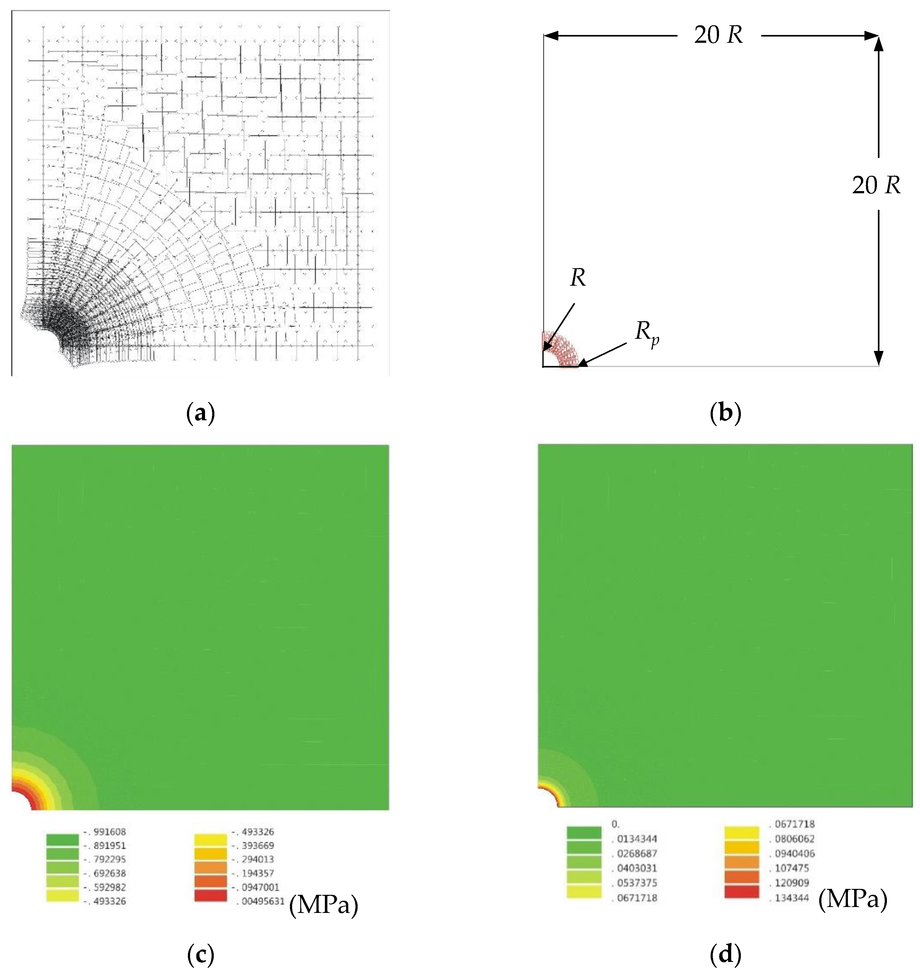
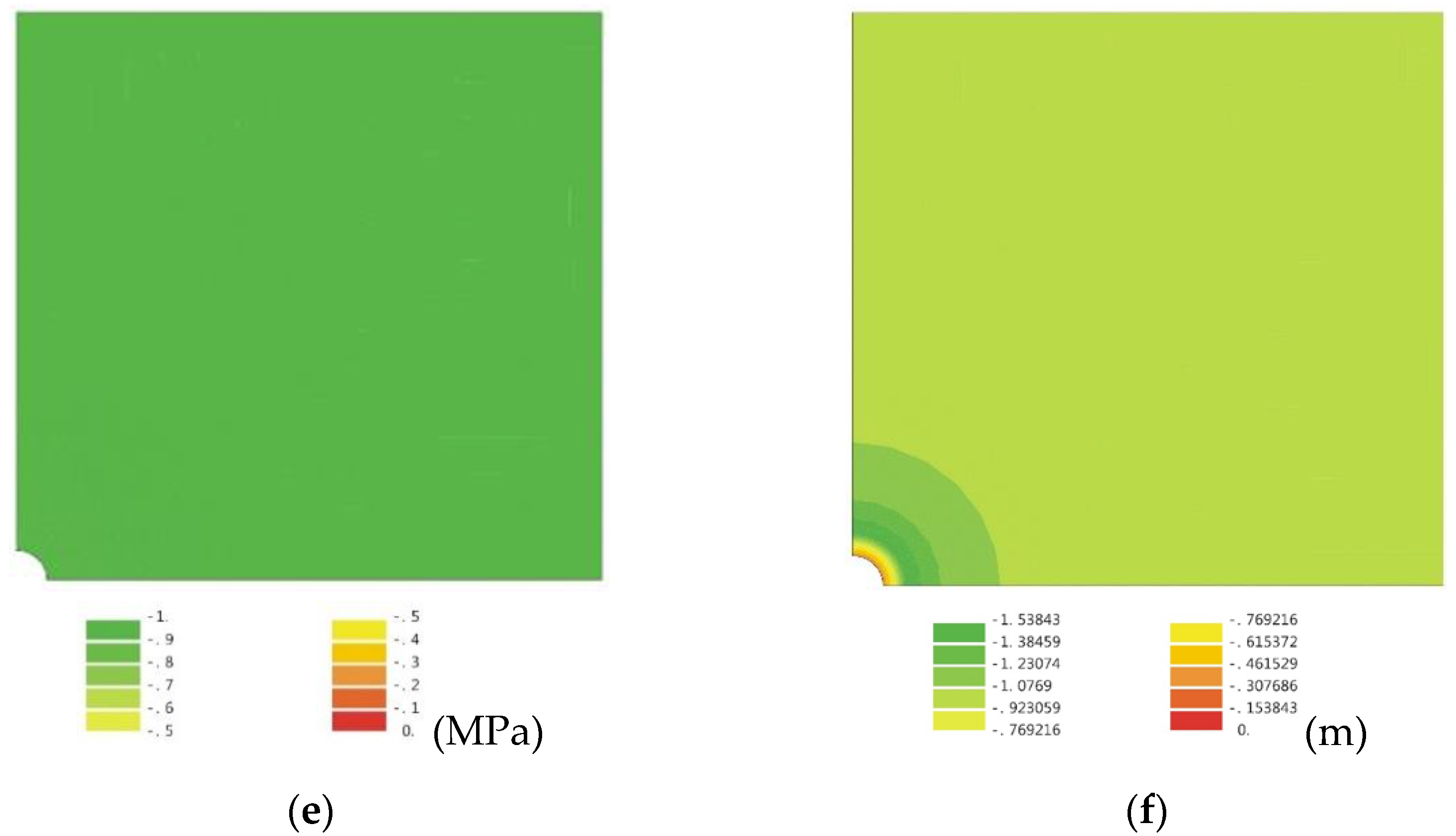
3.2. Procedure of Numerical Analysis for the FEM

To examine the results obtained by DCM, a numerical analysis that provides rigorous results for comparison, such as the finite element method (FEM), is investigated in this study. The finite element computing processor developed in the laboratory includes (1) the pre-processor (matrix optimization, boundary condition needed, mesh modeling, applied force, input data of material used, and geometry), (2) the main program (mechanic models, tolerance used, and the core of calculation including the increment steps), and (3) the post-processor (iso-value illustrations, drawing the contour line of displacement/stress, and output data).
The mesh made by finite element analysis includes 1971 total nodes and 658 elements (118 T6 elements and 540 Q8 elements), using three components of calculation (ground, excavation, and lining), and the analysis boundary of the roller support is 20 times the tunnel excavation radius. The simulation results obtained by the FEM comprise the displacements/stresses of the ground around the periphery of the tunnel. In addition, Figure 3 shows a plot of simulation results for tunnel excavation under initial isotropic stress condition and includes the plastic zone, the stress field, the total displacement, the minor principal stress, the major principal stress, and the iso-value illustrations of the initial stress. The input data used for the calculation are shown in Table 1.

4. Verification and Comparison of Results between This Study and Other Research

4.1. Verification and Comparison of Results between FEM and DCM

The feasibility of the developed direct algorithmic process (DCM) is verified by numerical analysis with finite element analysis (FEM). The comparison of analytical and numerical results, including the displacement/stress change of GRC and SCC in each excavation stage, and especially the influence of radial displacement and mobilized support pressure at the equilibrium point is investigated.
Considering the influence of tunnel-advancing excavation, the unsupported span d (or unsupported distance) is usually used to consider the influence of the stress state. If the tunnel is excavated without considering the support system, it is clear that the in situ stress will drop rapidly to a plastic state. Therefore, under the isotropic stress condition, two unsupported spans were selected including (1) short unsupported span (λd = 0.4, d = 0.53 m) so that the surrounding rock stress falls in the elastic zone, and (2) long unsupported span (λd = 0.7, d = 1.37 m) so that the stress falls in the plastic zone.
According to the results obtained by FEM and DCM for the support–ground interaction, the displacement/stress at the equilibrium state is different in the elastic region (Figure 4a) and the plastic region (Figure 4b). From the comparison results, it can be found that the mobilized support pressure in the elastic zone shows a relatively high value, while the radial displacement indicates a lower value, but the situation in the plastic zone shows the opposite. Furthermore, it must be noted that the trajectory of the support–ground interaction follows the ground reaction curve so, in this case, the interaction curve (IC) and the ground reaction curve (GRC) coincide with each other, i.e., the isotropic stress field.
The mechanical behavior is demonstrated in this study for the displacement/stress continuity at the elastoplastic interface as shown in Figure 5, that is, the continuous connection between the interface (between the elastic and plastic regions). For the comparison of the distribution of displacement/stress around circular tunnel proximity, the radial displacement and the plastic zone radius of the ground under no support condition are larger than the support condition. In other words, the support installation in tunneling blocks the development of the plastic zone (Figure 5a). On the comparison between FEM and DCM in numerical analysis, the results obtained at the intrados of the tunnel are approximatively the same as shown in Table 2, and that around the tunnel proximity illustrates a consistent trend as shown in Figure 5.

4.2. Comparison of Results between DCM and Other Studies

The case study compared with DCM includes research such as Rocksupport (2004) [36], Oreste (2009) [6], and Gschwandtner-Galler (2012) [23]. First of all, for analyzing the ground reaction caused by the tunnel excavation under the no support condition, the input data of the numerical calculation can be found in the aforementioned articles. According to the analysis results between DCM and the listed articles, the percentage error of the plastic zone radius is from 0.79% to 1.31%, and the percentage error of the radial displacement is from 0.24% to 1.70%. In particular, compared with the results of Rocksupport (2004), this study presents values with little error, as shown in Figure 6 and Table 3.
Regarding the comparison of DCM calculation results with published research articles, firstly, the input data of the calculation proposed by the tutorial manual of Rocksupport (2004) [36] includes two support systems that are only rock bolts and rock bolt plus shotcrete lining. The results calculated by DCM are as shown in Table 4, and one can observe that the range of percentage error of the plastic zone radius is 2.6–2.7%, and the range of the percentage error is 2.2–5.2% for the radial displacement, and 8.7~10.0% for the mobilized support pressure.
Secondly, the comparison with the study of Oreste (2009), the results as shown in Table 5 that displays a short unsupported span, deep tunnel location, good quality of rock mass, and general support system. The percentage error of the mobilized support pressure, the radial displacement, and the plastic zone radius are 7%, 0.7%, and 1.7%, respectively.
Thirdly, for a comparison with the study of Gschwandtner-Galler (2012), the results are shown in Table 6. The percentage error of the mobilized support pressure, the radial displacement, and the plastic zone radius are 7.6%, 1.9%, and 4.0%, respectively. Finally, for the comparison of results shown in Figure 7, the more obvious difference is the mobilized support pressure calculated by DCM, and the range of percentage error is between 7% and 10%.

5. Conclusions

Through a series of formula derivation, algorithm implementation, numerical verification, and comparison with three published research results, this study can draw the following conclusions:
(1)
The direct calculation method (DCM) is used to study the theoretical explanation and numerical analysis of the support–ground interaction caused by a circular tunnel excavation in the isotropic stress field.
(2)
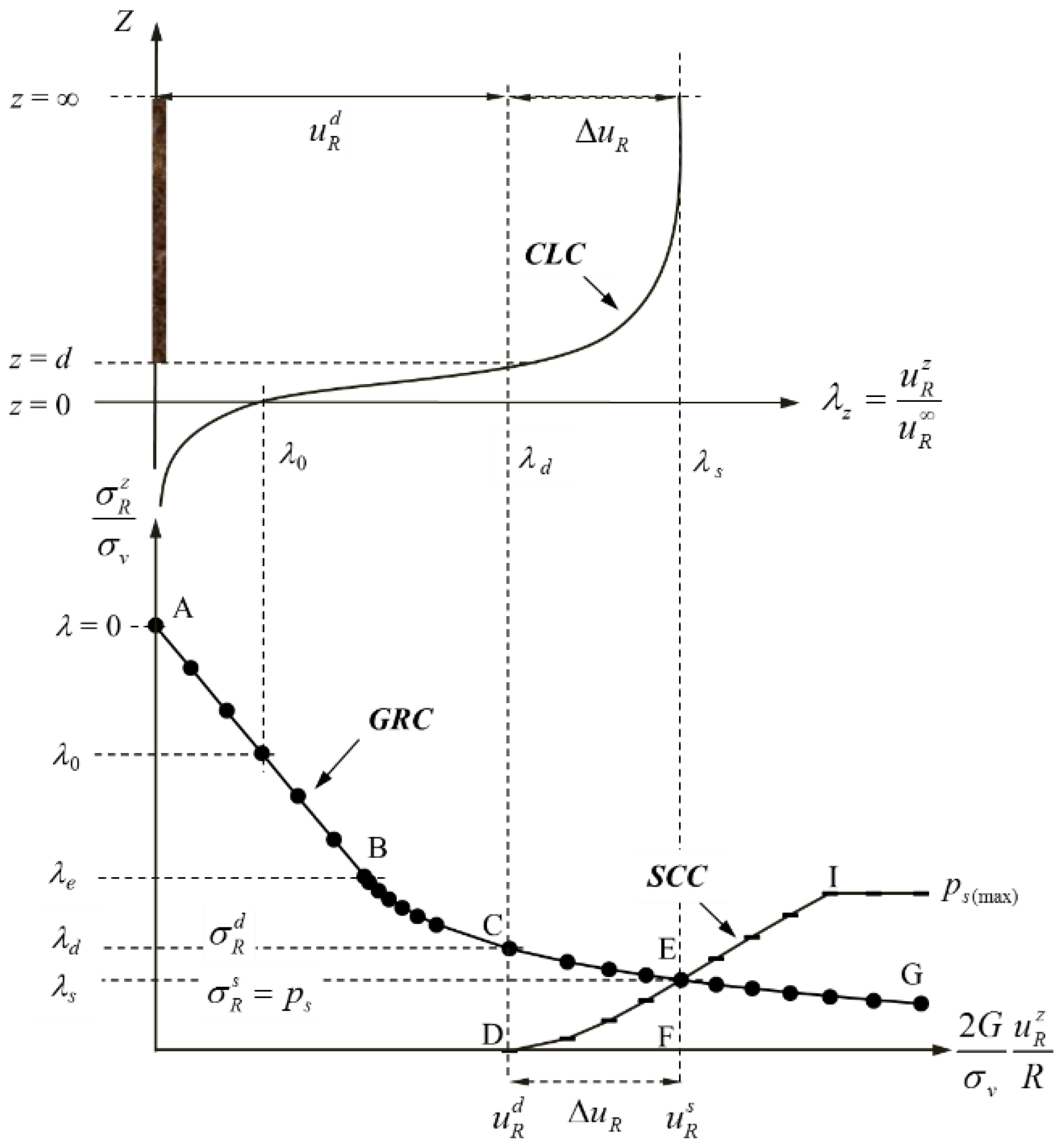
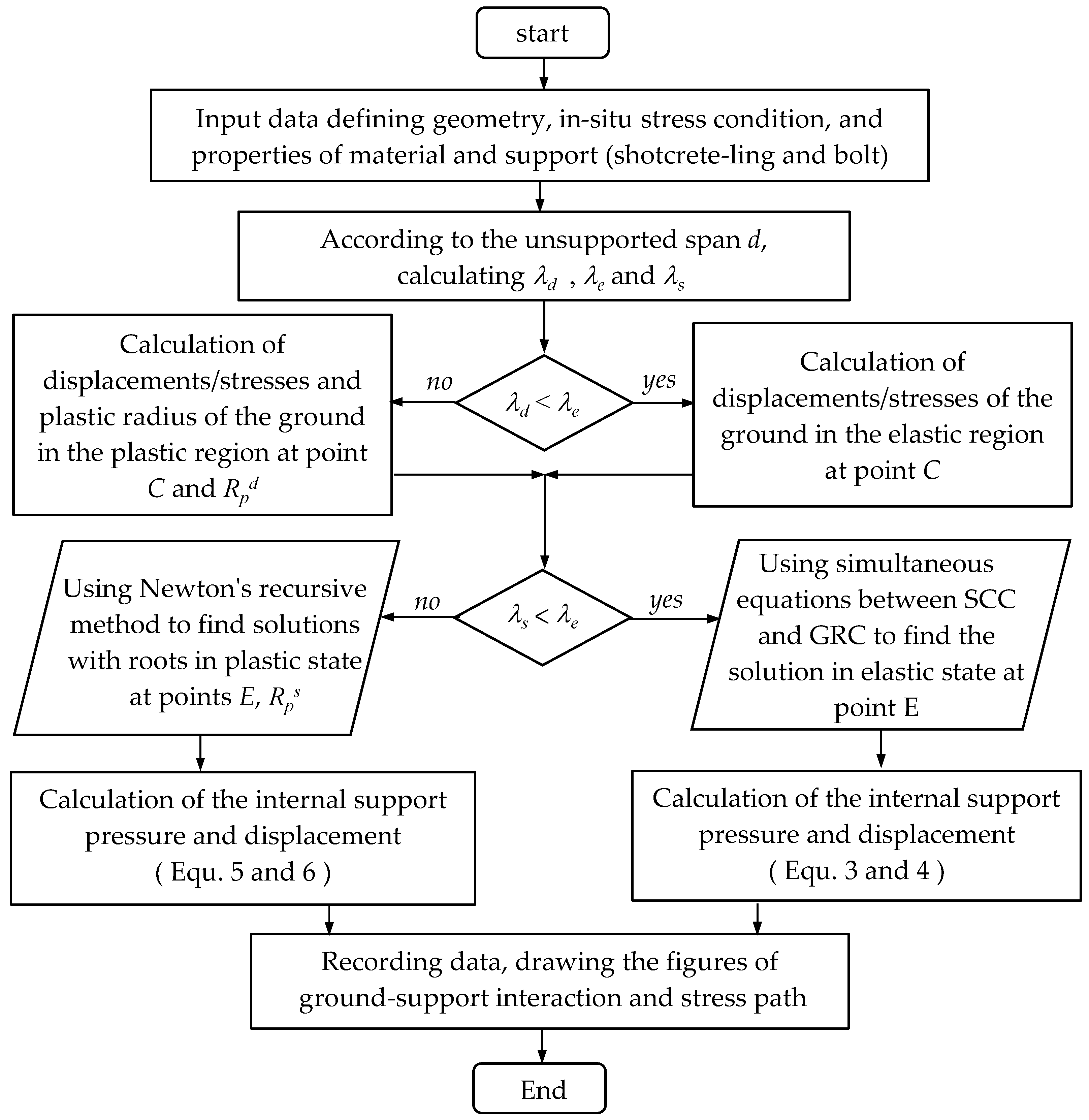
The DCM is proposed to provide a special algorithmic process to solve the support-ground interaction solution at the equilibrium state. The roots are obtained by applying the method of simultaneous equations in the elastic region and Newton’s recurrence method in the plastic region. DCM investigated the solution for the interaction between GRC and SCC, namely the mobilized support pressure and the radial displacement.
(3)
To resolve the theoretical analysis into an executable numerical program, a simple spreadsheet of calculations is used to realize the application of DCM.
(4)
The confinement loss as the incremental factor defining the situation of tunnel advancing excavation is classified by two cases (Case I and II) and proposed to distinguish whether the stress state is in the plastic or the elastic regions.
(5)
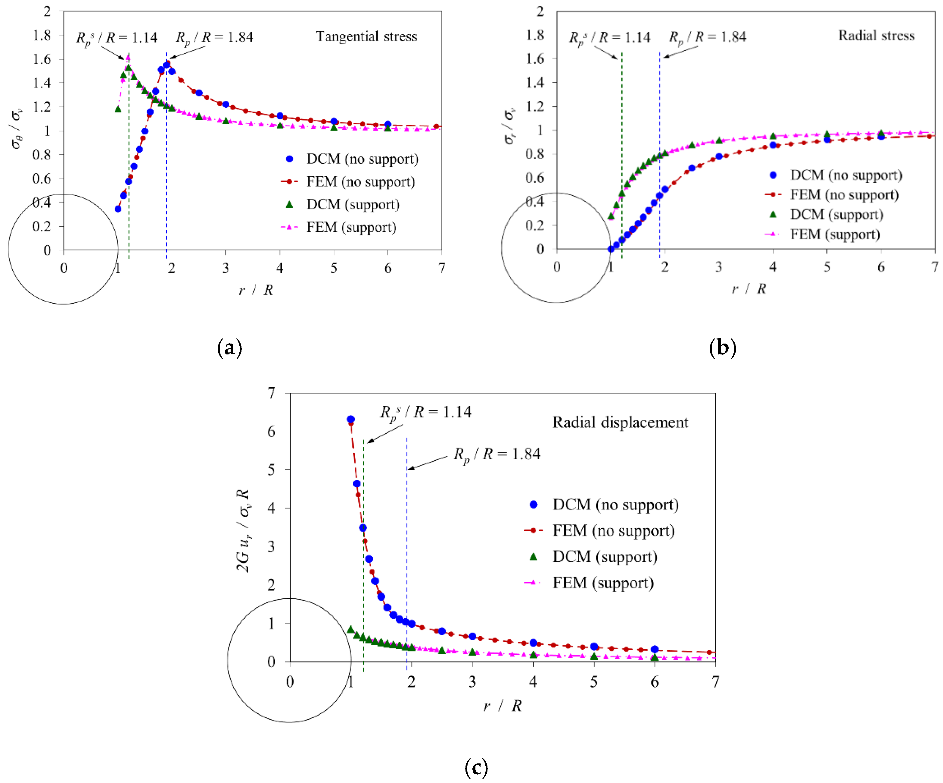
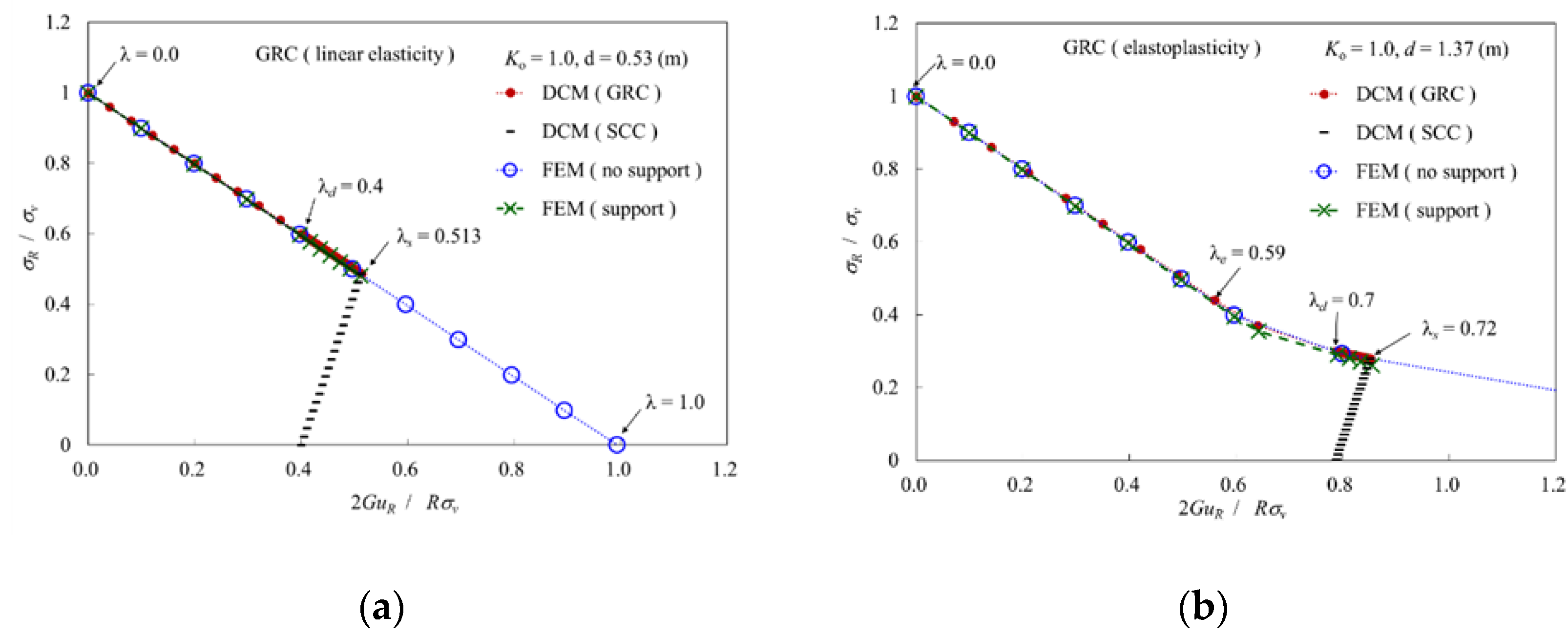
Good validation results are obtained between FEM and DCM for tunnel excavation simulations under support or no support conditions.
(6)
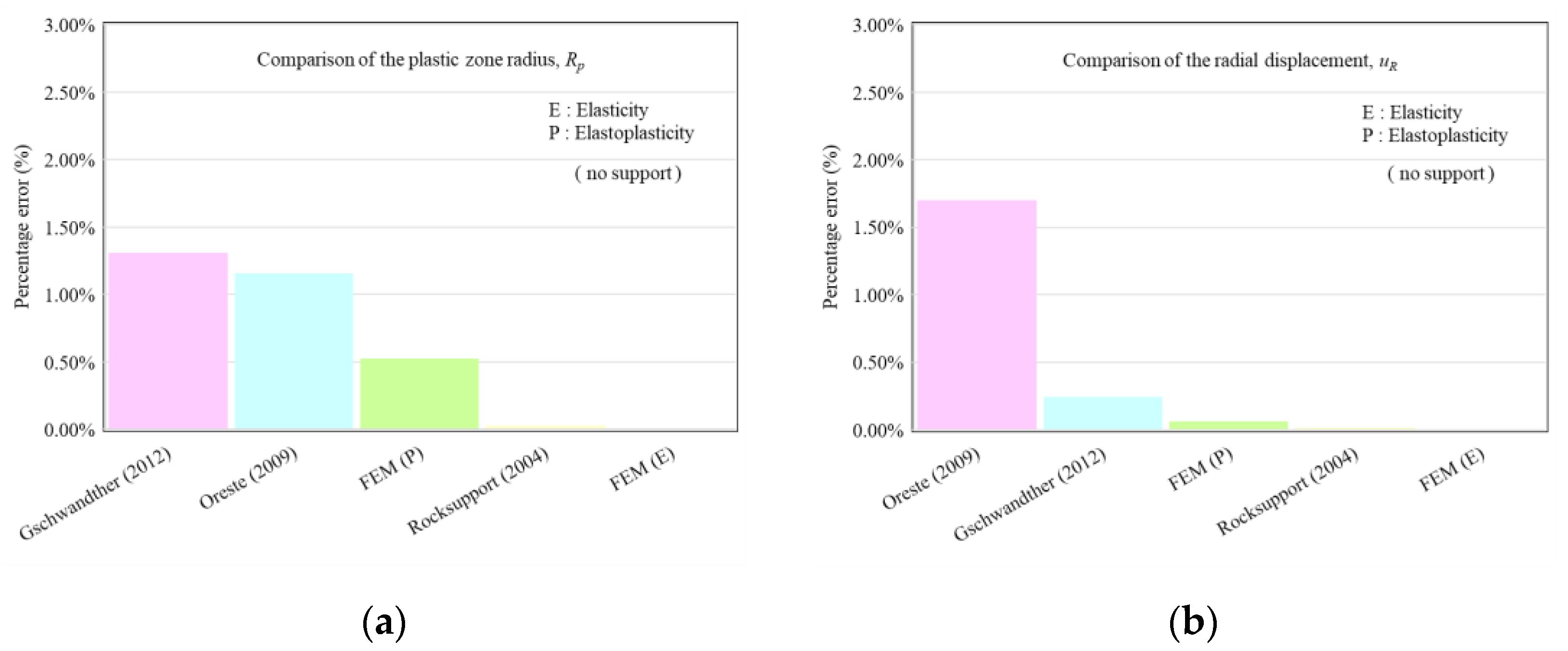
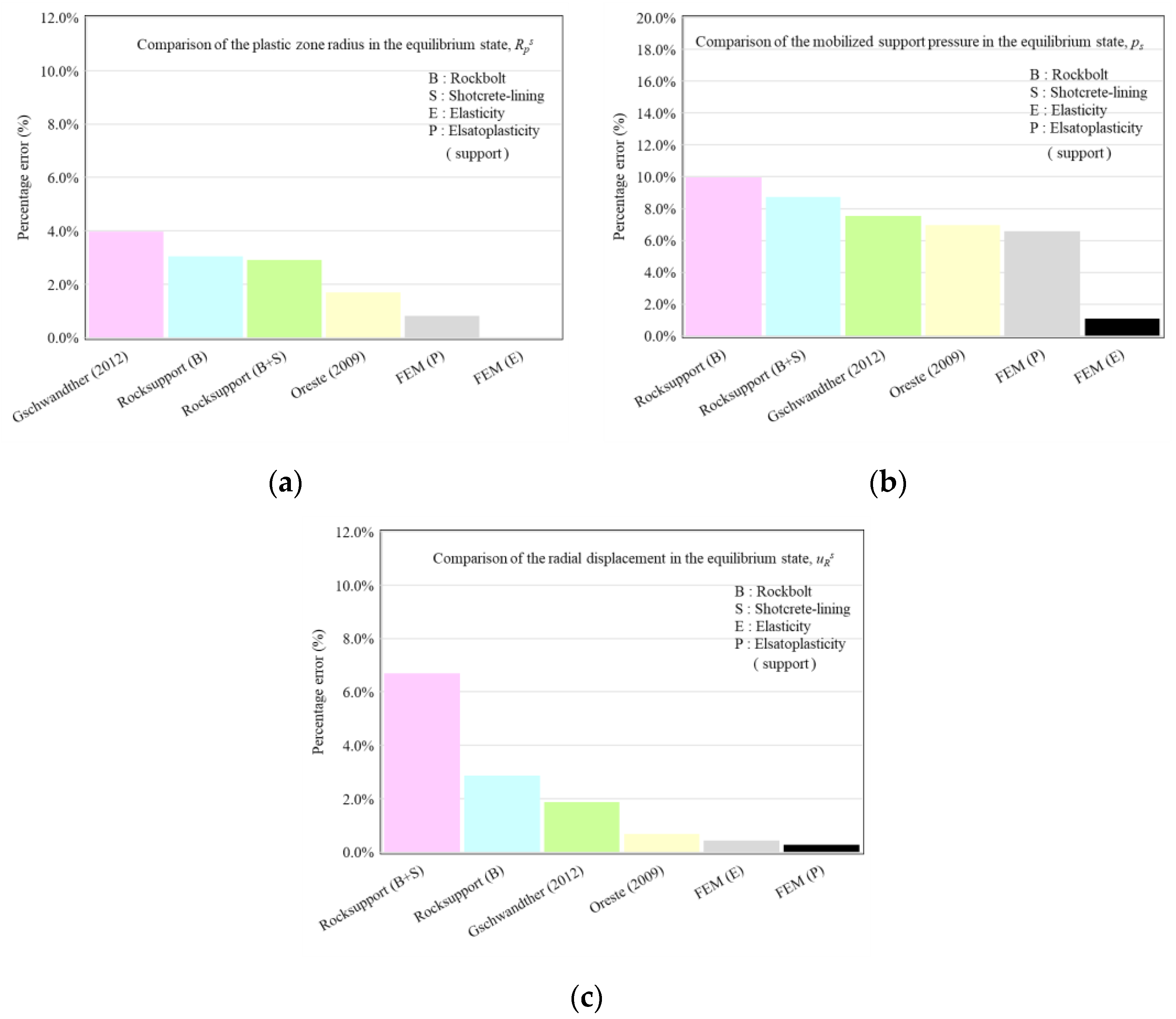
Three research results, Rocksupport (2004) [36], Oreste (2009) [6], and Gschwandtner-Galler (2012) [23], are used to compare with that obtained by DCM. In the no support condition, the consistency of the results is also very good. In the support condition, the maximum percentage error is 10%, 6%, and 4% for the mobilized support pressure, the radial displacement, and the plastic zone radius, respectively.

Author Contributions

Y.-L.L.: analysis, validation, and main editing and reviewing; W.-K.H. and P.-Y.C.: formula derivation and verification; P.-W.H., C.-H.M. and W.-C.K.: software programming and computation. All authors have read and agreed to the published version of the manuscript.

Funding

This research received no external funding.

Institutional Review Board Statement

Not applicable.

Informed Consent Statement

Not applicable.

Data Availability Statement

Not applicable.

Conflicts of Interest

The authors declare no conflict of interest. The sponsors had no role in the design, execution, interpretation, or writing of the study.

References

  1. Hoek, E.; Brown, E.T. Underground Excavations in Rock; The Institution of Mining and Metallurgy: London, UK, 1980. [Google Scholar]
  2. AFTES (Association Française des Tunnels et de l’Espace Souterrain). Recommandations pour l’emploi de la méthode convergence-confinement. Tunn. Ouvrages Souterr. 1983, 59, 119–138. [Google Scholar]
  3. Panet, M. Le Calcul des Tunnels par la Méthode de Convergence-Confinement; Presses de l’Ecole Nationale des Ponts et Chaussées: Paris, France, 1995. [Google Scholar]
  4. Panet, M. Recommendations on the Convergence-Confinement Method; Association Française des Tunnels et de l’Espace Souterrain (AFTES): Paris, France, 2001; pp. 1–11. [Google Scholar]
  5. Oreste, P. Analysis of structural interaction in tunnels using the convergence-confinement approach. Tunnell. Undergr. Space Technol. 2003, 18, 347–363. [Google Scholar] [CrossRef]
  6. Oreste, P. The convergence–confinement method: Roles and limits in modern geomechanical tunnel design. Am. J. Appl. Sci. 2009, 6, 757–771. [Google Scholar] [CrossRef] [Green Version]
  7. Sandrone, F.; Labiouse, V. Analysis of the evolution of road tunnels equilibrium conditions with a convergence-confinement approach. Rock Mech. Rock Eng. 2010, 43, 201–218. [Google Scholar] [CrossRef]
  8. Brown, E.T.; Bray, J.W.; Ladanyi, B.; Hoek, E. Ground response curves for rock tunnels. J. Geotech. Eng. ASCE 1983, 109, 15–39. [Google Scholar] [CrossRef]
  9. Brady, B.H.G.; Brown, E.T. Rock Mechanics for Underground Mining; Chapman & Hall: London, UK, 1993. [Google Scholar]
  10. Wang, Y. Ground response of a circular tunnel in poorly consolidated rock. J. Geotech. Eng. ASCE 1996, 122, 703–708. [Google Scholar] [CrossRef]
  11. Carranza-Torres, C.; Fairhurst, C. Application of the convergence-confinement method of tunnel design to rock masses that satisfy the Hoek–Brown failure criterion. Tunnell. Undergr. Space Technol. 2000, 15, 187–213. [Google Scholar] [CrossRef]
  12. Carranza-Torres, C. Elasto-plastic solution of tunnel problems using the generalized form of the Hoek-Brown failure criterion. Int. J. Rock Mech. Min. Sci. 2004, 41, 629–639. [Google Scholar] [CrossRef]
  13. Sharan, S.K. Exact and approximate solutions for displacements around circular openings in elastic-brittle plastic Hoek-Brown rock. Int. J. Rock Mech. Min. Sci. 2005, 42, 542–549. [Google Scholar] [CrossRef]
  14. Park, K.H.; Kim, Y.J. Analytical solution for a circular opening in an elastic–brittle–plastic rock. Int. J. Rock Mech. Min. Sci. 2006, 43, 616–622. [Google Scholar] [CrossRef]
  15. Guan, Z.; Jiang, Y.; Tanabasi, Y. Ground reaction analyses in conventional tunnelling excavation. Tunnell. Undergr. Space Technol. 2007, 22, 230–237. [Google Scholar] [CrossRef]
  16. Alejano, L.R.; Rodriguez-Dono, A.; Alonso, E.; Fdez-Manín, G. Ground reaction curves for tunnels excavated in different quality rock masses showing several types of post-failure behaviour. Tunnell. Undergr. Space Technol. 2009, 24, 689–705. [Google Scholar] [CrossRef]
  17. Serrano, A.; Olalla, C.; Reig, I. Convergence of circular tunnels in elastoplastic rock masses with non-linear failure criteria and non-associated flow laws. Int. J. Rock Mech. Min. Sci. 2011, 48, 878–887. [Google Scholar] [CrossRef]
  18. Zhang, Q.; Jiang, B.S.; Wang, S.L.; Ge, X.R.; Zhang, H.Q. Elasto-plastic analysis of a circular opening in strain-softening rock mass. Int. J. Rock Mech. Min. Sci. 2012, 50, 38–46. [Google Scholar] [CrossRef]
  19. Oreste, P.; Spagnoli, G. A combined analytical and numerical approach for the evaluation of radial loads on the lining of vertical shaft. Geotech. Geol. Eng. 2016, 34, 1057–1065. [Google Scholar] [CrossRef]
  20. Lee, Y.L. Explicit procedure and analytical solution for the ground reaction due to advance excavation of a circular tunnel in an anisotropic stress field. Geotech. Geol. Eng. 2018, 36, 3281–3309. [Google Scholar] [CrossRef]
  21. Lee, Y.L. Incremental procedure method for the analysis of ground reaction due to excavation of a circular tunnel by considering the effect of overburden depth. Tunnell. Undergr. Space Technol. 2019, 93, 1–16. [Google Scholar] [CrossRef]
  22. Oreste, P.; Peila, D. Modelling progressive hardening of shotcrete in convergence-confinement approach to tunnel design. Tunnell. Undergr. Space Technol. 1997, 12, 425–431. [Google Scholar] [CrossRef]
  23. Gschwandtner, G.G.; Galler, R. Input to the application of the convergence confinement method with time-dependent material behavior of the support. Tunnell. Undergr. Space Technol. 2012, 27, 13–22. [Google Scholar] [CrossRef]
  24. Rodríguez, R.; Díaz-Aguado, M.B. Deduction and use of an analytical expression for the characteristic curve of a support based on yielding steel ribs. Tunnell. Undergr. Space Technol. 2013, 33, 159–170. [Google Scholar] [CrossRef]
  25. Cui, L.; Zheng, J.; Zhang, R.; Lai, H. A numerical procedure for the fictitious support pressure in the application of the convergence-confinement method for circular tunnel design. Int. J. Rock Mech. Min. Sci. 2015, 78, 336–349. [Google Scholar] [CrossRef]
  26. Carranza-Torres, C.; Engen, M. The support characteristic curve for blocked steel sets in the convergence-confinement method of tunnel support design. Tunnell. Undergr. Space Technol. 2017, 69, 233–244. [Google Scholar] [CrossRef]
  27. Oke, J.; Vlachopoulos, N.; Diederichs, M. Improvement to the convergence-confinement method: Inclusion of support installation proximity and stiffness. Rock Mech. Rock Eng. 2018, 51, 1495–1519. [Google Scholar] [CrossRef]
  28. De La Fuente, M.; Taherzadeh, R.; Sulem, J.; Nguyen, X.S.; Subrin, D. Applicability of the convergence-confinement method to full-face excavation of circular tunnels with stiff support system. Rock Mech. Rock Eng. 2019, 52, 2361–2376. [Google Scholar] [CrossRef]
  29. Bernaud, D.; Rousset, G. The new implicit method for tunnel analysis. Int. J. Numer. Anal. Methods Geomech. 1996, 20, 673–690. [Google Scholar] [CrossRef]
  30. González-Nicieza, C.; Álvarez-Vigil, A.E.; Menéndez-Díaz, A.; González-Palacio, C. Influence of the depth and shape of a tunnel in the application of the convergence-confinement method. Tunnell. Undergr. Space Technol. 2008, 23, 25–37. [Google Scholar] [CrossRef]
  31. Mousivand, M.; Maleki, M.; Nekooei, M.; Msnsoori, M.R. Application of Convergence-Confinement method in analysis of shallow non-circular tunnels. Geotech. Geol. Eng. 2017, 35, 1185–1198. [Google Scholar] [CrossRef]
  32. Mousivand, M.; Maleki, M. Constitutive models and determining methods effects on application of Convergence-Confinement method in underground excavation. Geotech. Geol. Eng. 2018, 36, 1707–1722. [Google Scholar] [CrossRef]
  33. Vlachopoulos, N.; Diederichs, M. Improved longitudinal displacement profiles for convergence confinement analysis of deep tunnels. Rock Mech. Rock Eng. 2009, 42, 131–146. [Google Scholar] [CrossRef]
  34. Panet, M.; Guenot, A. Analysis of convergence behind the face of a tunnel. In Proceedings of the 3rd International Symposium, Brighton, UK, 7–11 June 1982; pp. 197–204. [Google Scholar]
  35. Humbert, P.; Dubouchet, A.; Fezans, G.; Remaud, D. CESAR-LCPC, un progiciel de calcul dédié au génie civil. Bull. Des Lab. Ponts Chaussées 2005, 256, 7–37. [Google Scholar]
  36. Rocksupport. Rock Support Interaction and Deformation Analysis for Tunnels in Weak Rock; Tutorial Manual of Rocscience Inc.; Rocscience Inc.: Toronto, ON, Canada, 2004; pp. 1–76. [Google Scholar]
  37. Lee, Y.L.; Lin, M.Y.; Hsu, W.K. Study on relationship between the confinement loss and the longitudinal deformation curve by using three-dimensional finite element analysis. Chin. J. Rock Mech. Eng. 2008, 27, 258–265. [Google Scholar]
  38. Lee, Y.L.; Hsu, W.K.; Lin, M.Y. Analysis of the advancing effect and the confinement loss by using deformation measurement in tunneling. Chin. J. Rock Mech. Eng. 2009, 28, 39–46. [Google Scholar] [CrossRef] [Green Version]
  39. Lee, Y.L. Prise en Compte des Non-Linéarité de Comportement des Sols et des Roches dans la Modélisation du Creusement d’un Tunnel. Ph.D. Thesis, École Nationale des Ponts et Chaussées, Paris, France, 1994. Available online: https://pastel.archives-ouvertes.fr/pastel-00569423 (accessed on 28 September 2021).
  40. Lee, Y.L. Explicit analysis for the ground-support interaction of circular tunnel excavation in anisotropic stress fields. J. Chin. Inst. Eng. 2020, 43, 13–26. [Google Scholar] [CrossRef]
Figure 1. Graphical concept of the support-ground interaction in the analysis of convergence-confinement method (CCM).
Applsci 12 01929 g001
Figure 2. Computation flowchart of the algorithmic process of direct calculation method (DCM).
Applsci 12 01929 g002
Figure 3. Simulation results of a circular tunnel excavation calculated by finite element analysis. (a) the stress field, (b) the plastic zone, (c) the major principal stress, (d) the minor principal stress, (e) the initial stress, and (f) the total displacement.
Applsci 12 01929 g003aApplsci 12 01929 g003b
Figure 4. Comparison of the interaction behavior of support-ground between FEM and DCM. (a) short unsupported span (d = 0.53 m), and (b) long unsupported span (d = 1.37 m).
Applsci 12 01929 g004
Figure 5. Distribution of the displacement/stress around a circular tunnel proximity under the support and no support condition by the comparison results obtained between FEM and DCM. (a) the tangential stress (σθ), (b) the radial stress (σr), and (c) the radial displacement (ur).
Applsci 12 01929 g005
Figure 6. Percentage error of results between DCM and other studies under no support condition. (a) the plastic zone radius (Rp), and (b) the radial displacement (uR).
Applsci 12 01929 g006
Figure 7. Percentage error of results at the equilibrium state between DCM and other studies under the support condition. (a) the plastic zone radius ( R p s ), (b) the mobilized support pressure ( p s ), and (c) the radial displacement ( u R s ).
Applsci 12 01929 g007
Table 1. Input data of the numerical computation of DCM and finite element method (FEM).
GroundSupport (Shotcrete-Lining)
ParameterValueParameterValue
Vertical stress, σv (MPa)1.0Poisson’s ratio, νshot 0.2
In-situ stress ratio, Ko1.0Elastic modulus, Eshot (GPa)25.0
Cohesion, c (MPa)0.1Unit weight, γshot (MPa/m)0.025
Friction angle, φ (°)30.0Uniaxial compression strength, σc(shot) (MPa)20.0
Dilation angle, ψ (°)30.0Thickness, tshot (m)0.2
Poisson’s ratio, ν0.25Unsupported span, d (m)0.53, 1.37
Elastic modulus, E (MPa)300.0Coefficients, m0.75
Confinement loss, λ0.0–1.0Tunnel radius, R (m)5.2
Table 2. Comparison of results between FEM and DCM.
FEMDCM
Support condition Mobilized   support   pressure ,   p s (MPa) Radial   displacement ,   u R s (mm) Plastic   zone   radius ,   R p s (m) Mobilized   support   pressure ,   p s (MPa)
(error %) *
Radial   displacement ,   u R s (mm)
(error %) *
Plastic   zone   radius ,   R p s (m) (error %) *
No support (Elasticity)n/a21.665n/an/a21.667
(0.01%)
n/a
No support (Elastoplasticity)n/a136.739.62n/a136.83
(0.07%)
9.57
(0.53%)
Support
λd = 0.53 a
0.48111.074n/a0.487
(1.1%)
11.124
(0.5%)
n/a
Support
λd = 1.37 b
0.26218.5345.9720.279
(6.6%)
18.482
(0.3%)
5.923
(0.8%)
a short unsupported span, b long unsupported span; * error (%) = 100%(|FEM-DCM|/FEM).
Table 3. Comparison of results between DCM and other studies (no support condition).
Other Research Results
(No Support Condition)
Radial Displacement, uR (mm)Plastic Zone Radius, Rp (m)DCM
Radial Displacement, uR (mm) (Error %)
DCM
Plastic Zone Radius, R p s (m) (Error %)
Rocksupport (2004)121.5613.77119.75
(1.49%)
13.66
(0.79%)
Oreste (2009)6.24.656.306
(1.70%)
4.704
(1.16%)
Gschwandtner-Galler (2012)160.013.0160.39
(0.24%)
12.83
(1.31%)
Table 4. Comparison of results between DCM and Rocksupport (2004) [36] (support condition).
Rocksupport (2004)DCM
Support condition Mobilized   support   pressure ,   p s (MPa) Radial   displacement ,   u R s (mm) Plastic   zone   radius ,   R p s (m) Mobilized   support   pressure ,   p s (MPa) (error %) Radial   displacement ,   u R s (mm) (error %) Plastic   zone   radius ,   R p s (m) (error %)
Rock bolts0.1960.010.00.171
(10.0%)
61.29
(2.15%)
10.27
(2.70%)
Rock bolt and shotcrete-lining0.2155.569.740.191
(8.7%)
58.42
(5.15%)
9.99
(2.57%)
Table 5. Comparison of results between DCM and Oreste (2009) [6] (support condition).
Oreste (2009)DCM
Mobilized   support   pressure ,   p s (MPa) Radial   displacement ,   u R s (mm) Plastic   zone   radius ,   R p s (m) Mobilized   support   pressure ,   p s (MPa)
(error %)
Radial   displacement ,   u R s (mm)
(error %)
Plastic   zone   radius ,   R p s (m)
(error %)
0.164.684.650.144
(7.0%)
4.65
(0.7%)
4.57
(1.7%)
Table 6. Comparison of results between DCM and Gschwandtner-Galler (2012) [23] (support condition).
Gschwandtner-Galler (2012)DCM
Mobilized   support   pressure ,   p s (MPa) Radial   displacement ,   u R s (mm) Plastic   zone   radius ,   R p s (m) Mobilized   support   pressure ,   p s (MPa)
(error %)
Radial   displacement ,   u R s (mm)
(error %)
Plastic   zone   radius ,   R p s (m)
(error %)
0.8475.27.690.904
(7.56%)
73.72
(1.97%)
8.00
(4.03%)
Publisher’s Note: MDPI stays neutral with regard to jurisdictional claims in published maps and institutional affiliations.

