
Impact Properties of Novel Natural Fibre Metal Laminated Composite Materials

 , , ,
, , ,  ,
,
Abstract
:1. Introduction
2. Materials and Methods
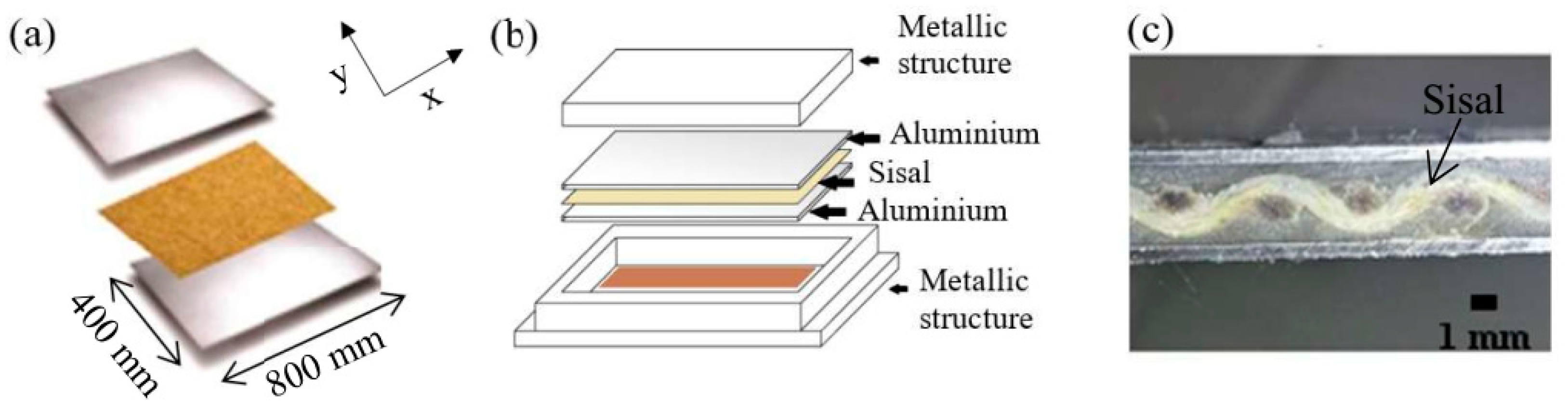
2.1. Materials
2.2. Preparation and Testing
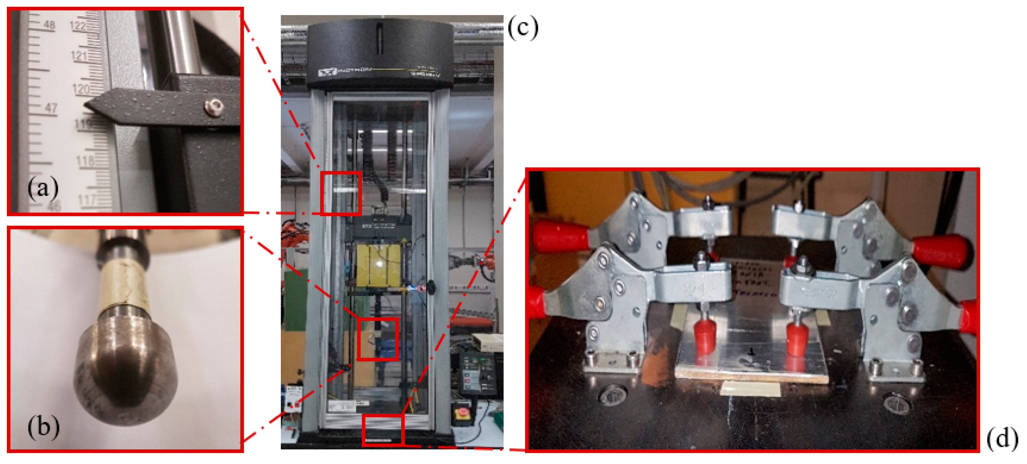
2.2.1. Drop Tower Impact Tests
2.2.2. Apparent Density
3. Results and Discussions
3.1. Impact Properties
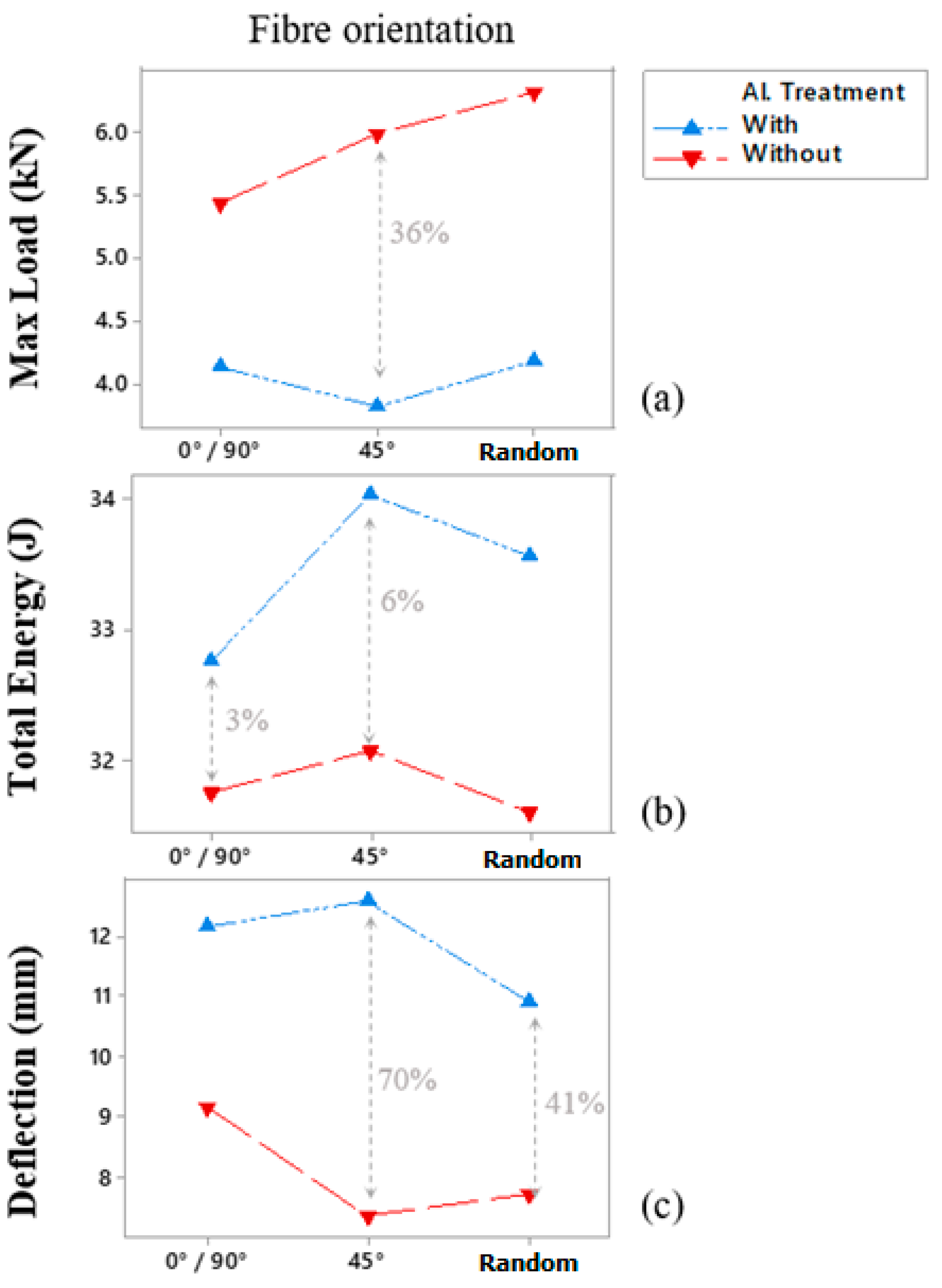
3.1.1. Maximum Load
3.1.2. Total Energy
3.1.3. Maximum Deflection
4. Conclusions
Author Contributions
Funding
Data Availability Statement
Acknowledgments
Conflicts of Interest
References
- Cortés, P.; Cantwell, W.J. The Impact Properties of High-temperature Fiber-Metal Laminates. J. Compos. Mater. 2006, 41, 613–632. [Google Scholar] [CrossRef]
- Vogelesang, L.; Vlot, A. Development of fibre metal laminates for advanced aerospace structures. J. Mater. Process. Technol. 2000, 103, 1–5. [Google Scholar] [CrossRef]
- Sinmazçelik, T.; Avcu, E.; Bora, M.Ö.; Çoban, O. A review: Fibre metal laminates, background, bonding types and applied test methods. Mater. Des. 2011, 32, 3671–3685. [Google Scholar] [CrossRef]
- McCombe, G.; Etches, J.; Mellor, P.; Bond, I. Development of a ferromagnetic fibre metal laminate. Compos. Part A Appl. Sci. Manuf. 2011, 42, 1380–1389. [Google Scholar] [CrossRef]
- Carrillo, J.; Cantwell, W. Mechanical properties of a novel fiber–metal laminate based on a polypropylene composite. Mech. Mater. 2009, 41, 828–838. [Google Scholar] [CrossRef]
- Rao, K.M.M.; Prasad, A.R. Fabrication and testing of natural fibre composites: Vakka, sisal, bamboo and banana. Mater. Des. 2010, 31, 508–513. [Google Scholar] [CrossRef]
- Yusoff, R.B.; Takagi, H.; Nakagaito, A.N. Tensile and flexural properties of polylactic acid-based hybrid green composites reinforced by kenaf, bamboo and coir fibers. Ind. Crop. Prod. 2016, 94, 562–573. [Google Scholar] [CrossRef]
- Vieira, L.M.G.; dos Santos, J.C.; Panzera, T.H.; Christoforo, A.L.; Mano, V.; Rubio, J.C.C.; Scarpa, F. Hybrid composites based on sisal fibers and silica nanoparticles. Polym. Compos. 2018, 39, 146–156. [Google Scholar] [CrossRef]
- Vasumathi, M.; Murali, V. Effect of Alternate Metals for use in Natural Fibre Reinforced Fibre Metal Laminates under Bending, Impact and Axial Loadings. Procedia Eng. 2013, 64, 562–570. [Google Scholar] [CrossRef] [Green Version]
- Zhang, J. Static indentation and impact behaviour of reformed bamboo/aluminium laminated composites. Compos. Struct. 2000, 50, 207–216. [Google Scholar] [CrossRef]
- Vieira, L.M.G.; dos Santos, J.C.; Panzera, T.H.; Rubio, J.C.C.; Scarpa, F. Novel fibre metal laminate sandwich composite structure with sisal woven core. Ind. Crop. Prod. 2017, 99, 189–195. [Google Scholar] [CrossRef] [Green Version]
- Malingam, S.D.; Feng, N.L.; Khoon, L.C.; Fadzullah, S.S.M.; Mustafa, Z.; Subramonian, S. The Influences of Fibre Parameters on the Tensile and Flexural Response of Lightweight Thermoplastic Kenaf Fibre Reinforced Metal Composites. J. Nat. Fibers 2018, 17, 966–978. [Google Scholar] [CrossRef]
- Hussain, M.; Imad, A.; Saouab, A.; Kanit, T.; Nawab, Y.; Herbelot, C.; Kashif, M. Properties and characterization of novel 3D jute reinforced natural fibre aluminium laminates. J. Compos. Mater. 2021, 55, 1879–1891. [Google Scholar] [CrossRef]
- Sevkat, E.; Liaw, B.; Delale, F. Drop-weight impact response of hybrid composites impacted by impactor of various geometries. Mater. Des. 2013, 52, 67–77. [Google Scholar] [CrossRef]
- Deng, Y.; Zhang, W.; Cao, Z. Experimental investigation on the ballistic resistance of monolithic and multi-layered plates against hemispherical-nosed projectiles impact. Mater. Des. 2012, 41, 266–281. [Google Scholar] [CrossRef]
- Laliberté, J.; Poon, C.; Straznicky, P.; Fahr, A. Post-impact fatigue damage growth in fiber–metal laminates. Int. J. Fatigue 2002, 24, 249–256. [Google Scholar] [CrossRef]
- Li, X.; Yahya, M.Y.; Nia, A.B.; Wang, Z.; Lu, G. Dynamic failure of fibre-metal laminates under impact loading—Experimental observations. J. Reinf. Plast. Compos. 2016, 35, 305–319. [Google Scholar] [CrossRef]
- Lee, D.-W.; Park, B.-J.; Park, S.-Y.; Choi, C.-H.; Song, J.-I. Fabrication of high-stiffness fiber-metal laminates and study of their behavior under low-velocity impact loadings. Compos. Struct. 2018, 189, 61–69. [Google Scholar] [CrossRef]
- Dhaliwal, G.S.; Newaz, G.M. Effect of Layer Structure on Dynamic Response and Failure Characteristics of Carbon Fiber Reinforced Aluminum Laminates (CARALL). J. Dyn. Behav. Mater. 2016, 2, 399–409. [Google Scholar] [CrossRef] [Green Version]
- Saniei, S.M.; Mashroteh, H.; Hadizadeh, M. An investigation into low-velocity impact resistance and tensile strength of aluminium-glass fabric hybrid composite. IOP Conf. Ser. Mater. Sci. Eng. 2017, 254, 42026. [Google Scholar] [CrossRef]
- Abdullah, M.; Cantwell, W. The impact resistance of polypropylene-based fibre–metal laminates. Compos. Sci. Technol. 2006, 66, 1682–1693. [Google Scholar] [CrossRef]
- ASTM Standard D7136/D7136M-15; Standard Test Method for Measuring the Damage Resistance of a Fi-ber-Reinforced Polymer Matrix Composite to a Drop-Weight Impact Event. ASTM International: West Conshohocken, PA, USA, 2015.
- Feraboli, P. Some Recommendations for Characterisation of Composite Panels by Means of Drop Tower Impact Testing. J. Aircr. 2006, 43, 1710–1718. [Google Scholar] [CrossRef]
- ASTM Standard D792/D792; Standard Test Methods for Density and Specific Gravity (Relative Density) of Plastics by Displacement. ASTM International: West Conshohocken, PA, USA, 2013.
- da Silva, L.J.; Panzera, T.H.; Velloso, V.R.; Christoforo, A.L.; Scarpa, F. Hybrid polymeric composites reinforced with sisal fibres and silica microparticles. Compos. Part B Eng. 2012, 43, 3436–3444. [Google Scholar] [CrossRef]
- de Oliveira, L.Á.; Tonatto, M.L.P.; Coura, G.L.C.; Freire, R.T.S.; Panzera, T.H.; Scarpa, F. Experimental and numerical assessment of sustainable bamboo core sandwich panels under low-velocity impact. Constr. Build. Mater. 2021, 292, 123437. [Google Scholar] [CrossRef]
- Oliveira, P.; Kilchert, S.; May, M.; Panzera, T.; Scarpa, F.; Hiermaier, S. Numerical and experimental investigations on sandwich panels made with eco-friendly components under low-velocity impact. J. Sandw. Struct. Mater. 2021, 24, 419–447. [Google Scholar] [CrossRef]
- Filho, S.L.M.R.; Oliveira, P.R.; Panzera, T.H.; Scarpa, F. Impact of hybrid composites based on rubber tyres particles and sugarcane bagasse fibres. Compos. Part B Eng. 2019, 159, 157–164. [Google Scholar] [CrossRef] [Green Version]
- Xu, Y.; Li, H.; Shen, Y.; Liu, S.; Wang, W.; Tao, J. Improvement of adhesion performance between aluminum alloy sheet and epoxy based on anodizing technique. Int. J. Adhes. Adhes. 2016, 70, 74–80. [Google Scholar] [CrossRef] [Green Version]
- Feraboli, P.; Kedward, K.T. Enhanced Evaluation of the Low-Velocity Impact Response of Composite Plates. AIAA J. 2004, 42, 2143–2152. [Google Scholar] [CrossRef]


| SiRAL Condition | Total Energy [J] | Max Load [Kn] | Total Deflection [mm] | Time to Max Load [ms] |
|---|---|---|---|---|
| 0°/90° | 31.77 ± 0.72 | 5.44 ± 0.25 | 9.16 ± 1.21 | 4.53 ± 0.50 |
| 0°/90° Al-Treated | 32.76 ± 0.89 | 4.13 ± 0.33 | 12.18 ± 1.38 | 6.36 ± 0.48 |
| +45°/−45° | 32.09 ± 0.86 | 5.99 ± 0.46 | 7.34 ± 1.14 | 3.65 ± 0.67 |
| +45°/−45° Al-Treated | 34.05 ± 0.62 | 3.81 ± 0.20 | 12.63 ± 1.29 | 4.47 ± 1.52 |
| Random | 31.61 ± 0.69 | 6.33 ± 0.27 | 7.73 ± 0.49 | 3.98 ± 0.46 |
| Random Al-Treated | 33.56 ± 0.76 | 4.17 ± 0.22 | 10.91 ± 0.82 | 5.67 ± 0.61 |
| Experimental Factors | Total Energy | Total Deflection | Max Load | |||
|---|---|---|---|---|---|---|
| p-Values (≤0.05) | F-Value | p-Values (≤0.05) | F-Value | p-Values (≤0.05) | F-Value | |
| Fibre orientation (FO) | 0.005 | 14.25 | 0.009 | 11.43 | 0.002 | 20.57 |
| Al Treatment (Al T) | 0.000 | 174.46 | 0.000 | 276.29 | 0.000 | 940.27 |
| FO × Al T | 0.030 | 6.69 | 0.013 | 9.92 | 0.002 | 21.65 |
| R² (adj) | 95.05% | 96.62% | 98.93% | |||
| Ryan-Joiner | 0.057 | >0.100 | >0.100 | |||
| Type | Front | Rear | Side | Core |
|---|---|---|---|---|
| 0/90 | 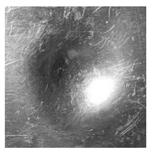 | 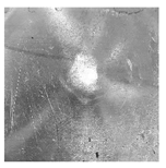 | 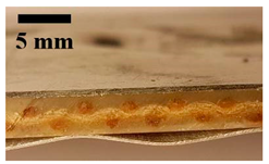 | 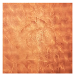 |
| 0/90 Pre-Al-treated | 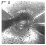 | 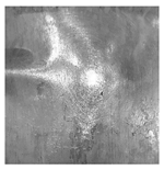 | 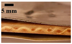 |  |
| +45°/−45° |  |  | 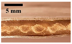 | 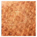 |
| +45°/−45° Pre-Al-treated | 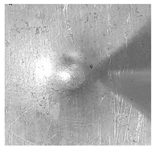 | 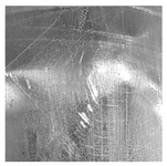 | 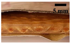 | 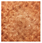 |
| Random | 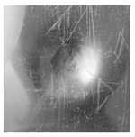 |  |  | 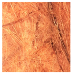 |
| Random Pre-Al-treated |  |  |  |  |
Publisher’s Note: MDPI stays neutral with regard to jurisdictional claims in published maps and institutional affiliations. |
© 2022 by the authors. Licensee MDPI, Basel, Switzerland. This article is an open access article distributed under the terms and conditions of the Creative Commons Attribution (CC BY) license (https://creativecommons.org/licenses/by/4.0/).
Share and Cite
Vieira, L.M.G.; Dobah, Y.; dos Santos, J.C.; Panzera, T.H.; Campos Rubio, J.C.; Scarpa, F. Impact Properties of Novel Natural Fibre Metal Laminated Composite Materials. Appl. Sci. 2022, 12, 1869. https://doi.org/10.3390/app12041869
Vieira LMG, Dobah Y, dos Santos JC, Panzera TH, Campos Rubio JC, Scarpa F. Impact Properties of Novel Natural Fibre Metal Laminated Composite Materials. Applied Sciences. 2022; 12(4):1869. https://doi.org/10.3390/app12041869
Chicago/Turabian StyleVieira, Luciano Machado Gomes, Yousef Dobah, Júlio César dos Santos, Túlio Hallak Panzera, Juan Carlos Campos Rubio, and Fabrizio Scarpa. 2022. "Impact Properties of Novel Natural Fibre Metal Laminated Composite Materials" Applied Sciences 12, no. 4: 1869. https://doi.org/10.3390/app12041869
APA StyleVieira, L. M. G., Dobah, Y., dos Santos, J. C., Panzera, T. H., Campos Rubio, J. C., & Scarpa, F. (2022). Impact Properties of Novel Natural Fibre Metal Laminated Composite Materials. Applied Sciences, 12(4), 1869. https://doi.org/10.3390/app12041869