Enlarged Head Pressure-Dispersed Anchor Cable for Foundation Pit Engineering Purposes
Abstract
1. Introduction
2. Analysis of the Force Mechanism
2.1. Composition of the Support System
2.2. Internal Force Analysis of the Anchor Cable
- (1)
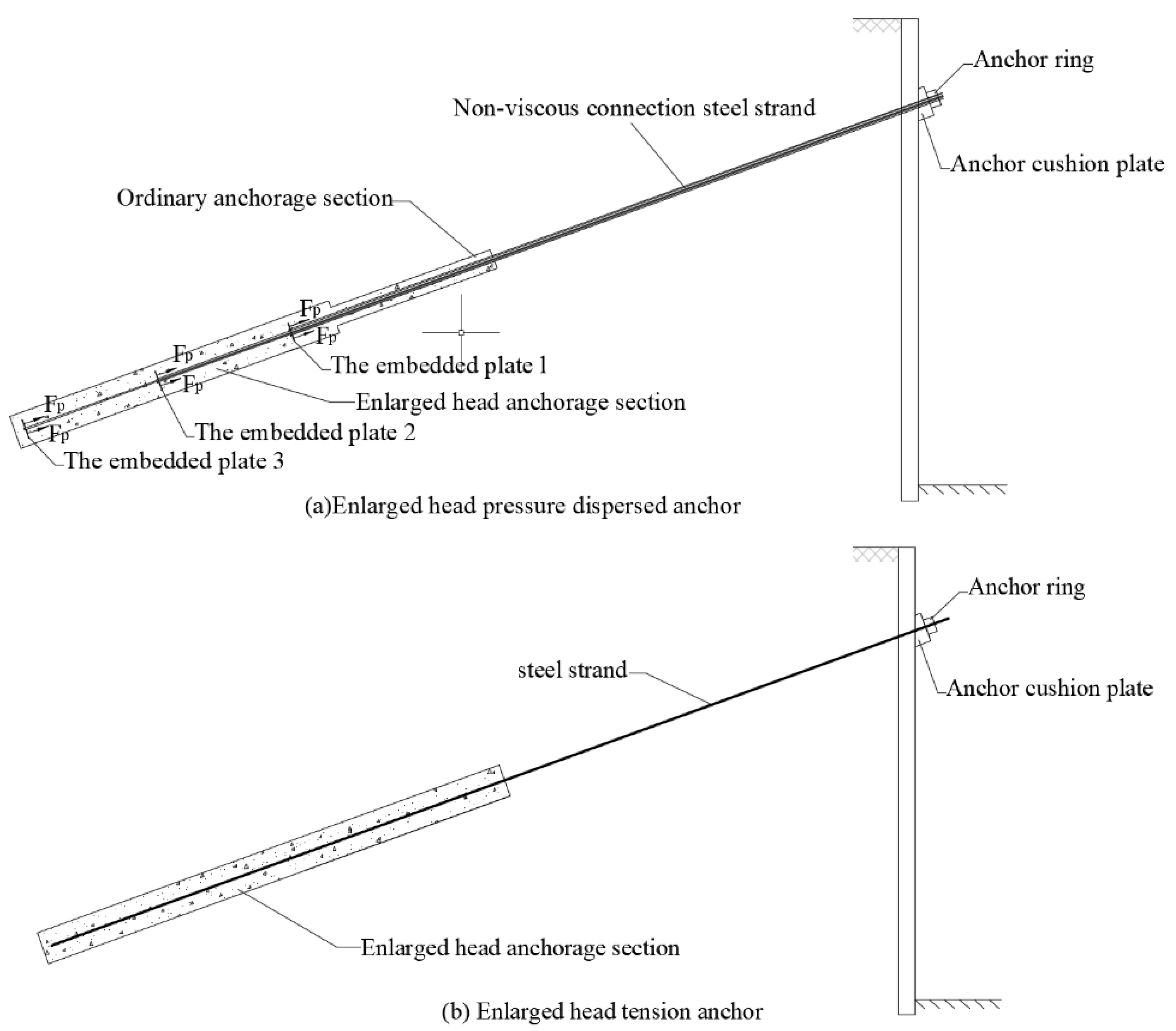
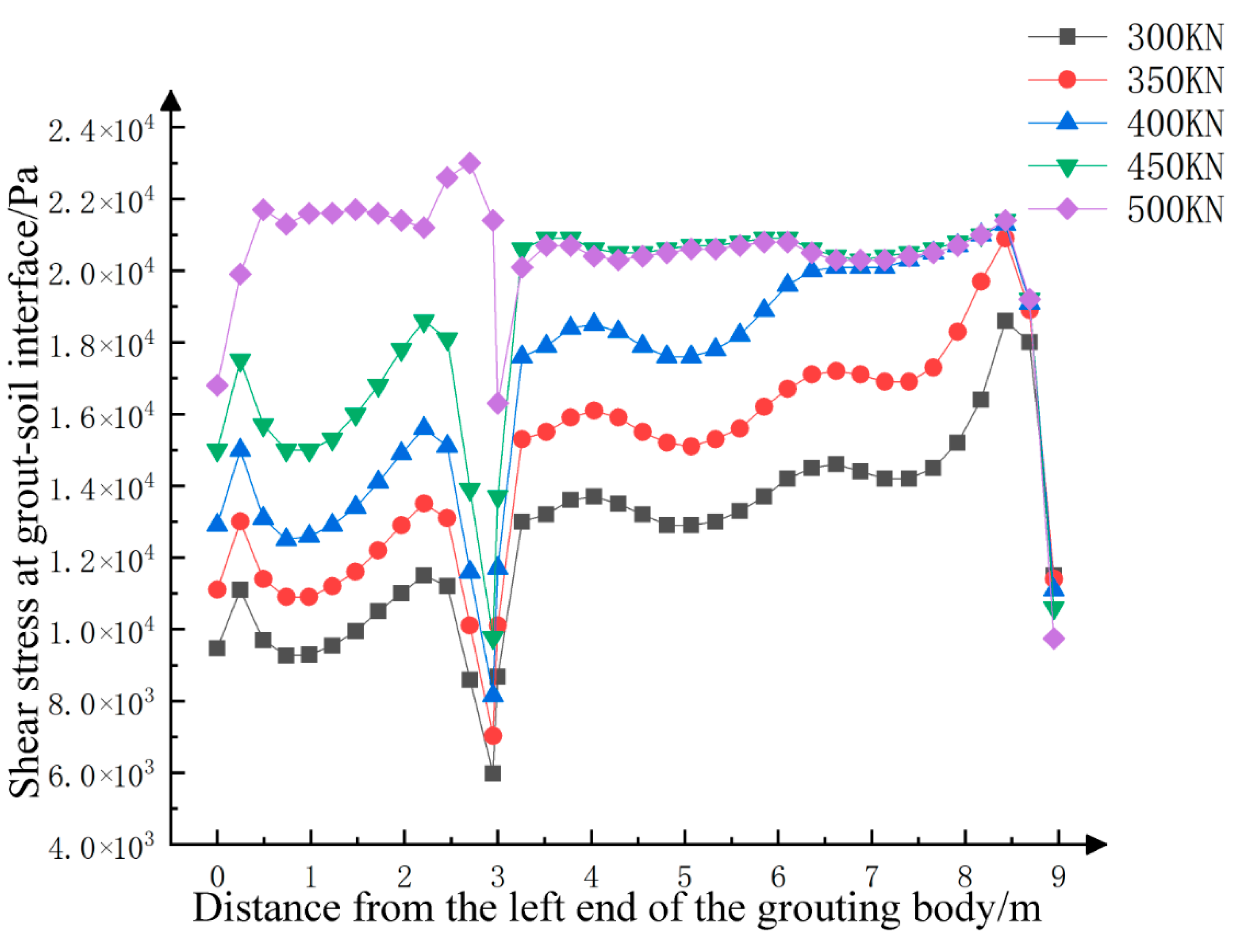
- Static earth pressure stage: In the initial stage of axial force growth at the anchor head and the anchor cable, there is only a relative displacement trend between the anchor solid and the soil, i.e., only the static friction force around anchor solid. It is pointed out in the relevant literature [24,25] that the generation of passive earth pressure requires a certain amount of displacement, while the displacement of the anchor solids at this stage is very small. Therefore, the extrusion of enlarged head anchor solids by the soil in front of the end is the static earth pressure. Due to the small displacement of the anchor cable in this stage, the pull-out bearing capacity is mainly provided by the side friction of the ordinary anchorage section and the enlarged head anchorage section.
- (2)
- Transition stage: As the load continues to increase, the interface will plastically yield when the stress state at the interface between the anchor solid and the soil interface reaches the shear strength. We continue to increase the tension of the anchor cable. Due to the insufficient shear strength of the soil mass, the soil mass around the anchor solid is damaged and connected. The enlarged head anchorage section and ordinary anchorage section have obvious displacement. The pressure of the soil mass on the end face of the enlarged head gradually increases, and the soil mass in front of the enlarged head end forms a plastic zone in the local set. A further increase in the axial tension of the anchor cable leads to the compaction in the soil at the front of the variable section, gradually forming a plastic sphere space. At this moment, the end pressure resistance becomes an important part of the bearing capacity, and the displacement growth rate in this stage is larger than that in the previous stage. Since the compression of the soil mass at the front of the enlarged head anchor cable is a progressive developmental process, the increase in the pull-out force at this stage is nonlinear. The displacement of the variable sections results in the extrusion of the front-end soil mass, which directly increases the end resistance. The soil mass at the front of the variable section is compressed all around, resulting in the compression of the soil mass at the front of a variable section and confined by the further soil mass and anchor solid.
- (3)
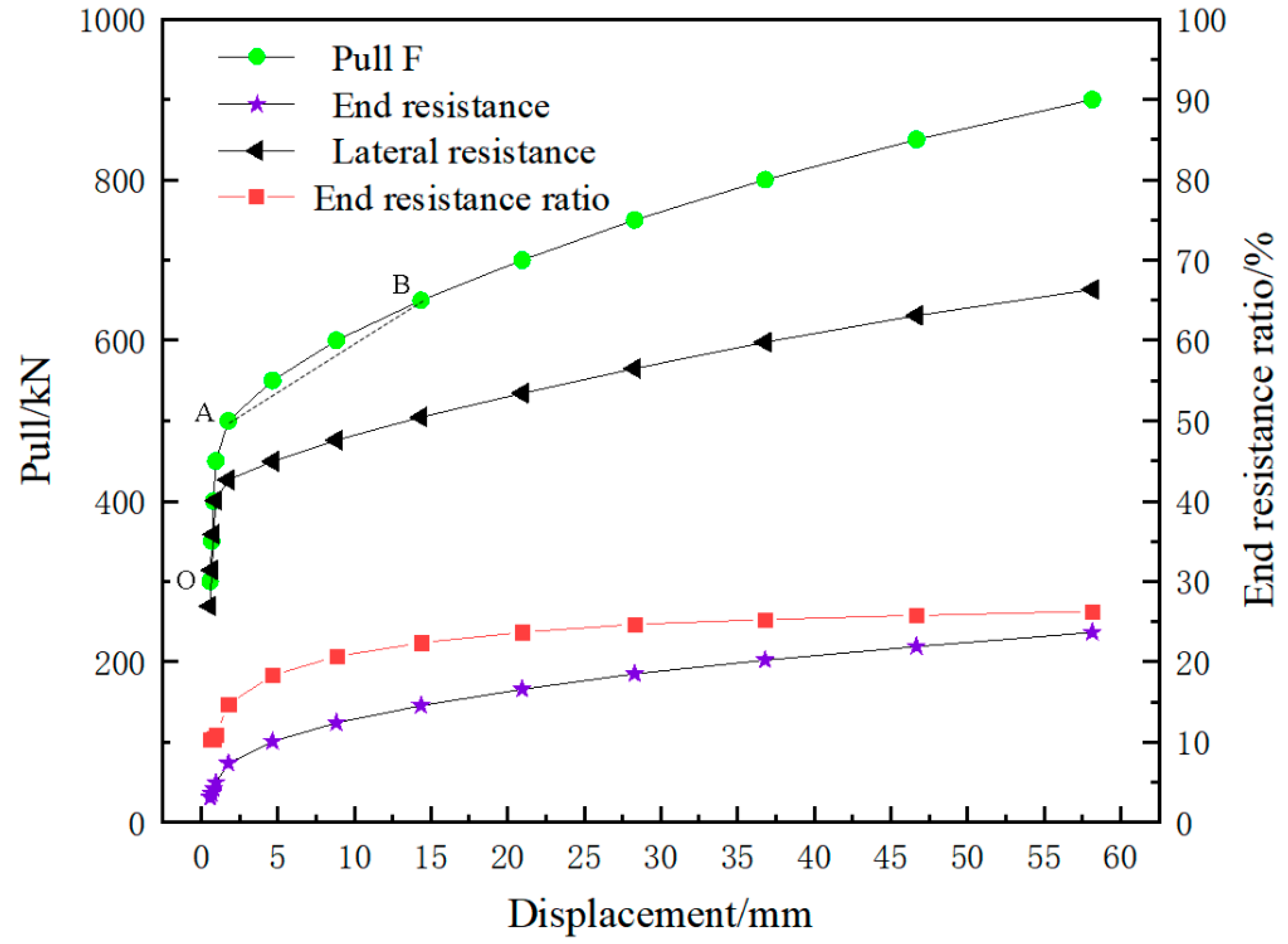
- Plastic development stage of soils in front of the end: With an increase in the tension, an obvious “end-pressing inflection point” appears on the tension F (the sum of axial force on the anchor head and anchor cable)-displacement S (the front end of the anchor solid) curve. Subsequently, the soil mass in the plastic zone becomes further compressed by the enlarged head and the surrounding soil mass, as shown in Figure 3. When the anchor cable is subject to tension F and produces displacement or deformation, the variable section of the enlarged head anchor cable will produce end resistance σ1, and shear stress τf will be generated between the soil and the anchor cable. The soil mass in the plastic zone is further squeezed by the enlarged head and the surrounding soil mass and further enhances the pressure σ2 of the soil mass on the enlarged head. The sliding surface of the soil mass in the front of the enlarged head no longer occurs along the grout–soil interface but moves outwards. Soil in the plastic zone undergoes a plastic expansion and internal force rebalancing at the same time. This process is similar to the plastic zone expansion before the shear failure of a foundation under vertical pressure. Soil in the plastic zone becomes compact under the confining pressure, which is essentially a process of increasing the “stiffness” of the plastic zone. As the surface area of the plastic zone increases, the soil provides a wider range of resistance. In order to achieve the mechanical balance of the anchor cable, the internal force of the soil is transferred directly to the front of the enlarged head through the plastic zone with increased rigidity. In addition, the compression modulus of the soil and the position of the interlayer in the soil also directly affect the expansion of the plastic zone and the magnitude of the end pressure.
2.3. End Resistance of the Enlarged Head Pressure-Dispersed Anchor Cable
3. Case Study of the Enlarged Head Tension Anchor Cable Support
3.1. Engineering Overview
3.2. Monitoring of Foundation Pit Engineering
4. Numerical Simulation Analysis of the Anchor–Cable Support System
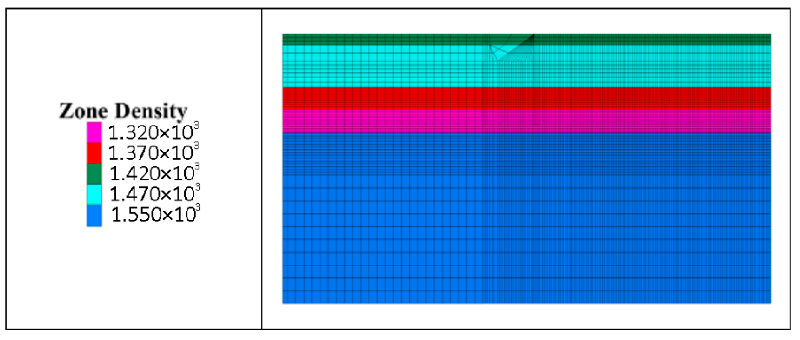
4.1. Selection of Soil Constitutive Model and Calculation Parameters
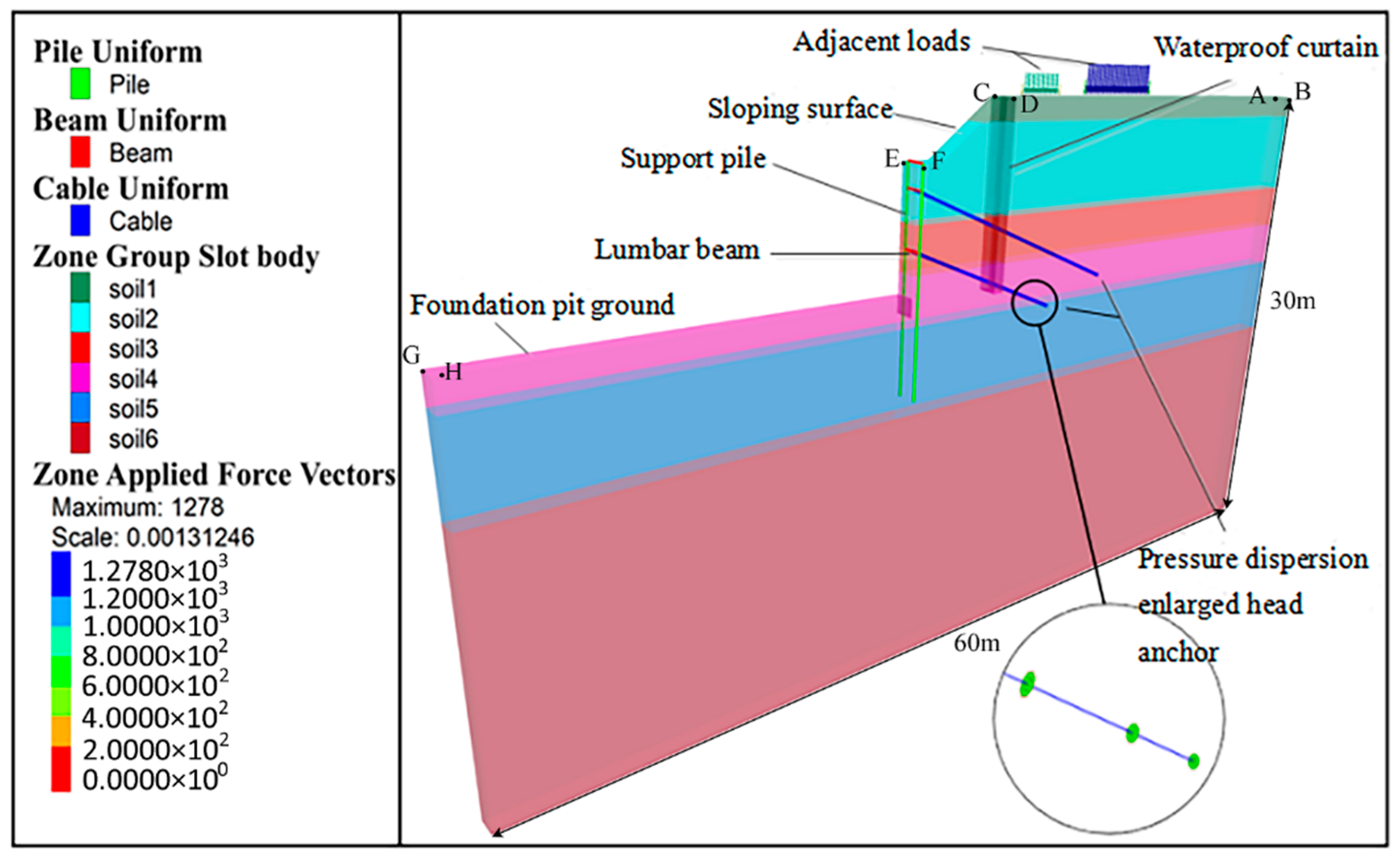
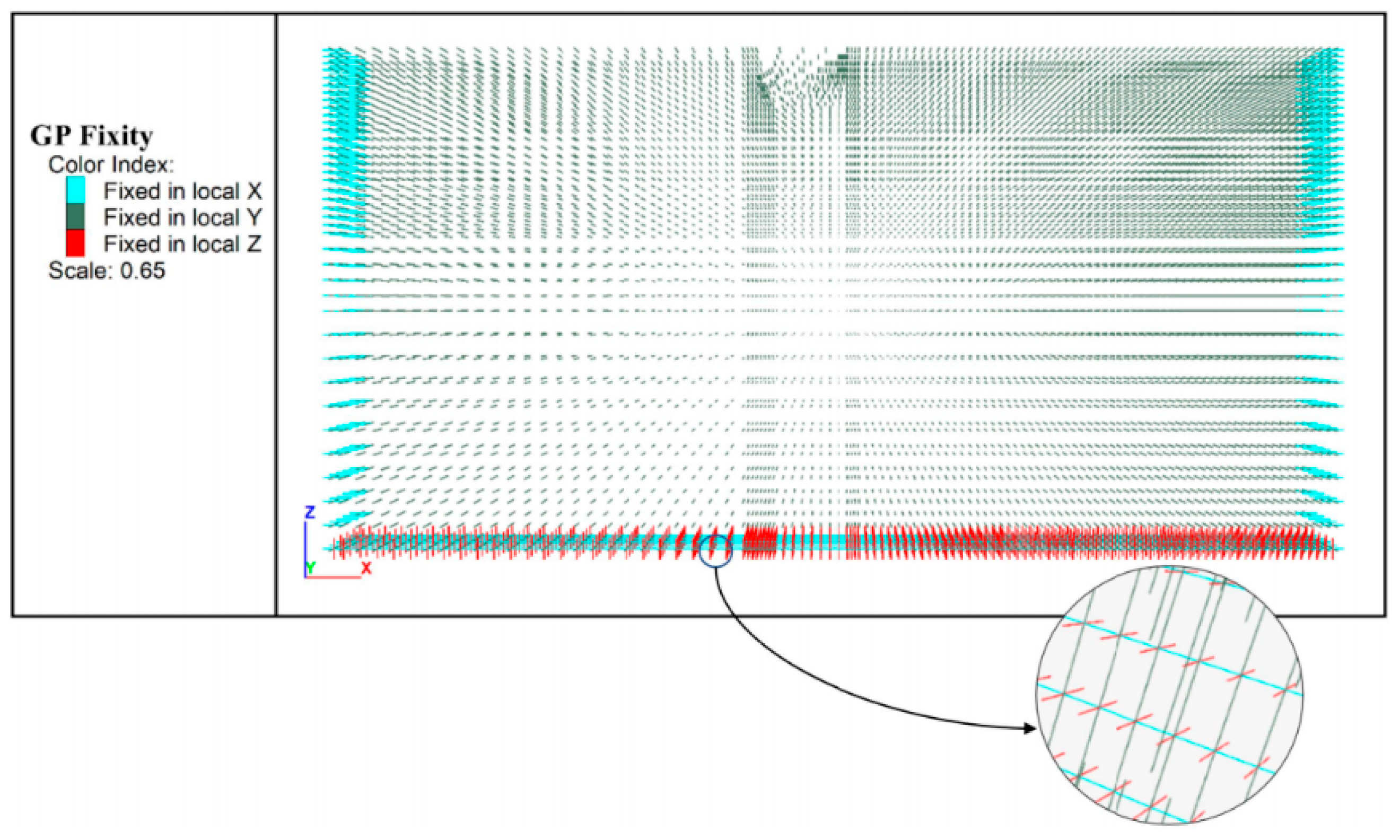
4.1.1. Calculation of Model Size and Determination of Boundary Conditions
4.1.2. Simulating Process of Foundation Pit Excavation
4.2. Results and Analysis of the Numerical Simulation
4.2.1. Support Effect of the Enlarged Head Pressure-Dispersed Anchor Cable on Foundation Pit
4.2.2. Comparison of Support Effects of Enlarged Head Pressure-Dispersed Anchor Cables and Enlarged Head Tension Anchor Cables
5. Conclusions
- (1)
- When the plastic zone at the grout–soil interface of anchor cable was penetrated, the end resistance at the variable section enhanced the side resistance. An “End-pressing inflection point” was caused by the different increasing speeds of the end resistance and side resistance, and with the increase in the tension, the maximum end resistance can reach 30% of the total tension, and an obvious plastic sphere space appeared at the front of the anchor.
- (2)
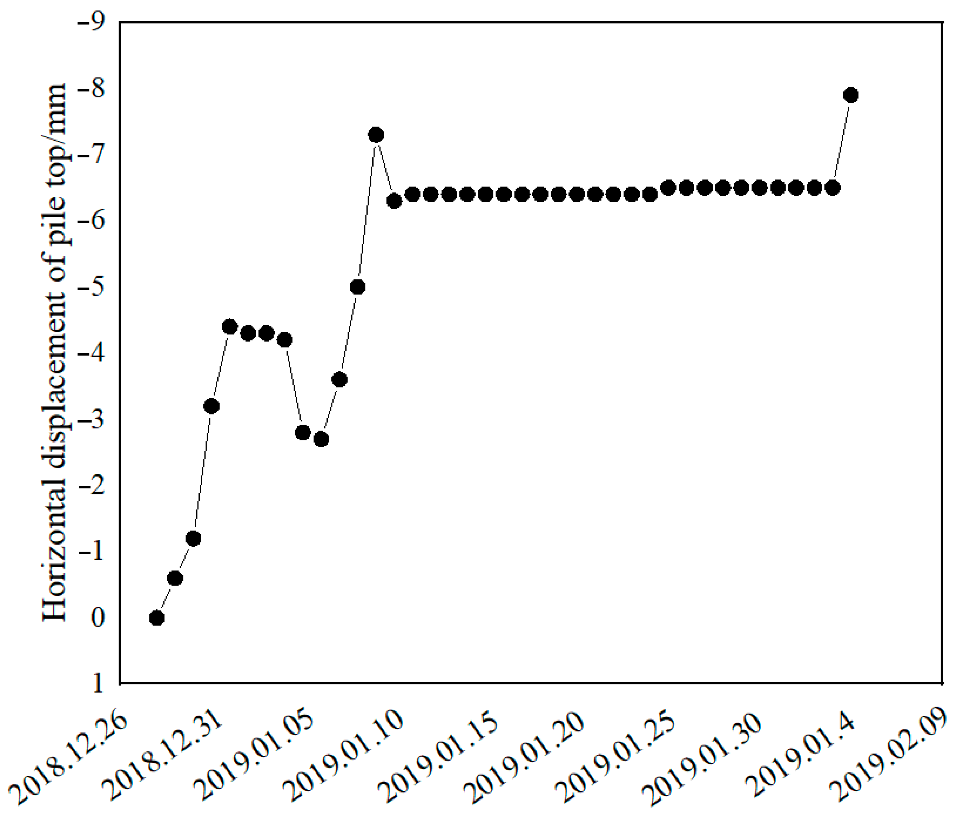
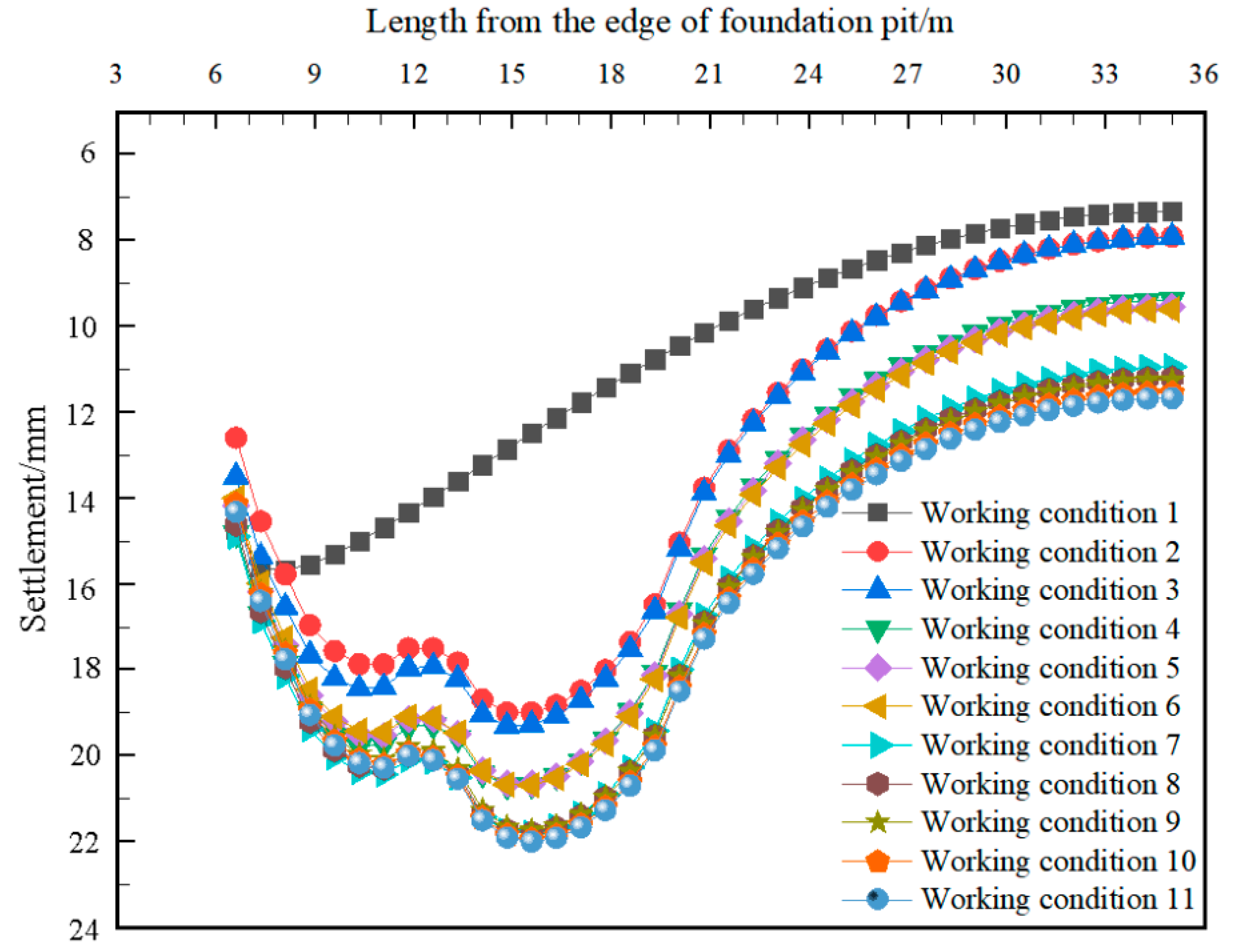
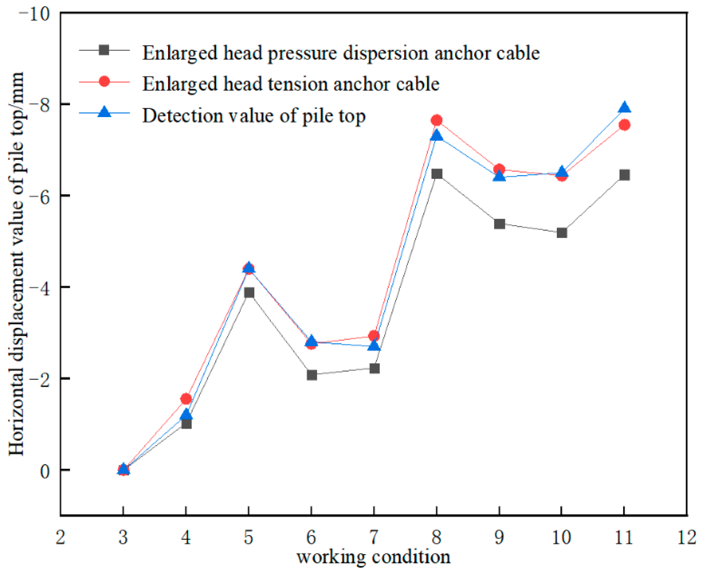
- In the numerical simulation, the conditions, such as saturated seepage, inclination of anchor cable, excavation of multi-layer soil body and loading at the side of a pit, were considered. By analyzing various conditions of the foundation pit excavation, it was found that the drainage process of the foundation pit increased the horizontal displacement of the support pile and the surface settlement around the foundation pit to a certain extent. The simulation results showed that the displacement results of both the types of anchor cables in this study were within the error range, and the maximum error between the simulation results of the tension-type anchor cables and the engineering monitoring values was only 0.4 mm, which verified the accuracy of the simulation.
- (3)
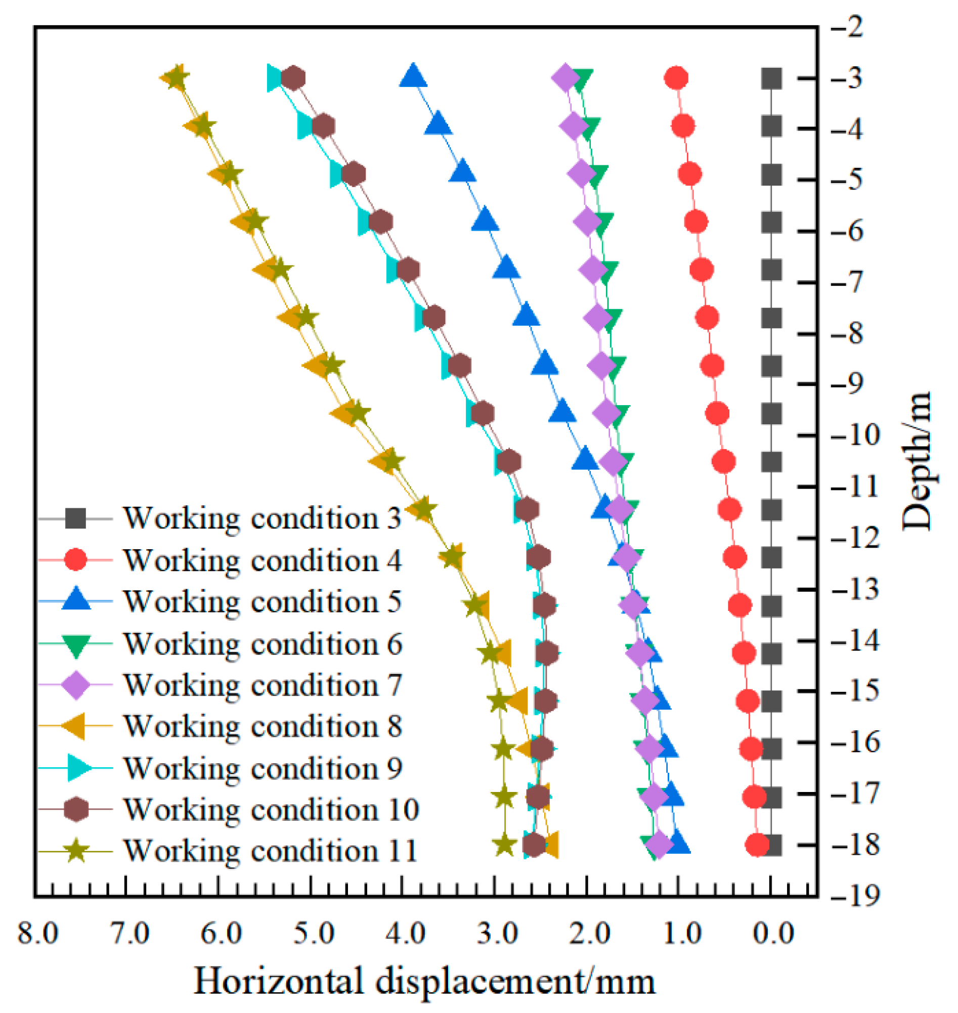
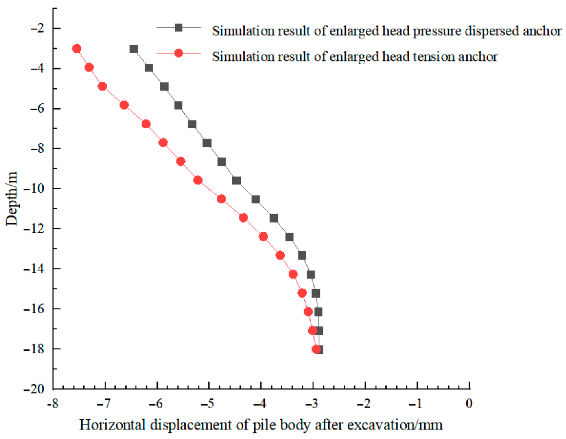
- After excavation, the horizontal displacement of pile body of the enlarged head pressure-dispersed anchor cable was significantly smaller than that of the enlarged head tension-type anchor cable compared with the simulation results of ordinary tension anchor cable. It shows that the displacement of enlarged head pressure-dispersed anchor cable decreases by 24.4%, which indicates that the support effect of the enlarged head pressure-dispersed anchor cable was superior to that of the enlarged head tension-type anchor cable. In general, the axial force of the enlarged head pressure anchor cables was less than that of the enlarged head tension cables, which was possibly due to the excavation depth and properties of surrounding soil and seepage. Therefore, in regard to the foundation pit support, the support effect of the enlarged head pressure-dispersed anchor cable was better than that of the enlarged head tension anchor cable.
Author Contributions
Funding
Conflicts of Interest
References
- Zeng, Q.; Yang, X.; Yang, C. Mechanical mechanism and calculation method of bit expanded anchor rods. Rock Soil Mech. 2010, 31, 1359–1367. [Google Scholar] [CrossRef]
- Chen, C.; Nemick, J.; Ting, R.; Aziz, N. A study of rock bolting failure modes. Int. J. Min. Sci. Technol. 2013, 23, 79–88. [Google Scholar] [CrossRef]
- Ling, Y.; Feng, Y. Development and Application of Anchor-Soil Interface Models. Soils Found. 2002, 41, 59–77. [Google Scholar] [CrossRef]
- Tao, Z.; Zhu, Z.; Han, W.; Zhu, C.; Liu, W. Static tension and finite element analysis of constant resistance and large deformation anchor cable. Adv. Mech. Eng. 2018, 10, 1–13. [Google Scholar] [CrossRef]
- Liu, G.; Wen, K.; Li, Z.; Hu, R. Field Test on Pressure-type Anchor with Enlarged-end. China Earthq. Eng. J. 2011, 33, 303–307. [Google Scholar]
- Su, T.; Zhou, Y.; Wang, Z.; Ye, S. Large Scale Model Test Study of Foundation Pit Supported by Pile Anchors. Appl. Sci. 2022, 12, 9792. [Google Scholar] [CrossRef]
- Dong, Y.; Cui, L.; Zhang, X. Multiple-GPU parallelization of three-dimensional material point method based on single-root complex. Int. J. Numer. Methods Eng. 2021, 123, 1481–1504. [Google Scholar] [CrossRef]
- Ren, D.; Chang, S.; Wang, G. Optimization Study on Structural Parameters of the Bit Expanded Anchor. J. Shenyang Jianzhu Univ. 2016, 32, 466–475. [Google Scholar] [CrossRef]
- Zhang, D.; Wang, R.; Jiang, Y.; Li, D.; Lin, G. Experimental Study on Anchoring Mechanism of Pre-Stressed Anchor Cable by FLAC3D. In Proceedings of the 2010 International Conference on Computational Intelligence and Software Engineering, Wuhan, China, 10–12 December 2010; pp. 1–4. [Google Scholar]
- Shan, R.; Huang, P.; Yuan, H.; Meng, C.; Zhang, S. Research on the full-section anchor cable and C-shaped tube support system of mining roadway in island coal faces. J. Asian Archit. Build. Eng. 2021, 31, 298–310. [Google Scholar] [CrossRef]
- Li, X.; Yang, G.; Nemick, J.; Aziz, N. Numerical investigation of the shear behaviour of a cable bolt in single shear test. Tunn. Under. Space Technol. 2019, 84, 227–236. [Google Scholar] [CrossRef]
- Yu, Y.; Liu, X. Flac3d Numerical Simulation of Tension-dispersive Anchor Cable. Electron. J. Geotech. Eng. 2014, 19, 6009–6019. [Google Scholar]
- Kim, N.; Park, J.; Kim, S. Numerical simulation of ground anchors. Comput. Geotech. 2006, 34, 498–507. [Google Scholar] [CrossRef]
- Dong, B.; Zhang, P.; Zhang, M.; Qu, Z.; Huang, W. Research on Deformation of Deep Foundation Pit Dewatering Excavation Based on Fluid-solid Coupling Effect. Highway 2021, 66, 349–356. [Google Scholar]
- Liu, H.; Feng, J. Study on Anchorage Mechanism of Pressure Dispersed Anchor by Numerical Analysis. Chin. J. Undergr. Space Eng. 2015, 11, 446–455. [Google Scholar]
- Wang, Z.; Wang, Q.; Ma, S.; Xue, Y.; Xu, S. A method for calculating ultimate pullout force of recoverable under-reamed prestressed anchor cable. Rock Soil Mech. 2018, 38, 202–208. [Google Scholar]
- Fan, N.; Jiang, J.; Dong, Y.; Guo, L.; Song, L. Approach for evaluating instantaneous impact forces during submarine slide- pipeline interaction considering the interaction considering the inertial action. Ocean Eng. 2022, 245, 110466. [Google Scholar] [CrossRef]
- Li, Q.; Zhang, L.; Liu, H.; Qin, J.; Wu, S. Research on the Strain Energy and the Stiffness Matching of Pressure-dispersive Anchor Cable. Chin. J. Undergr. Space Eng. 2019, 15, 1033–1037. [Google Scholar]
- Zhang, Y.; Zhao, H.; Zhang, X. Test Study of Mechanical Performances of Anchorage Zone of Pressure Dispersion Anchor Cable Style. Chin. J. Rock Mech. Eng. 2010, 29, 3052–3056. [Google Scholar]
- Yao, H.; Gan, K.; Wu, D.; Ren, Y.; Lv, W.; Duan, W. Research on anti-vibration ability of pressure dispersed anchor cable and tension concentrated anchor cable. Rock Soil Mech. 2012, 33, 3598–3603. [Google Scholar]
- Liang, Y.; Liu, G.; Li, Z.; Yang, J. Field Test on Sub-Enlarged Pressure-Dispersive Ground Anchor. Appl. Mech. Mater. 2012, 1800, 683–686. [Google Scholar] [CrossRef]
- Zhang, Z.; Liu, J.; Ye, G.; Liang, Z.; He, Z. Performance Tests on Pressure-Dispersed Compression Anchors in Cohesive Soils. Int. J. Geomech. 2021, 21, 04021012. [Google Scholar] [CrossRef]
- Li, J.; Li, L. Numerical analysis on a new pressure-type anchor cable with precast anchor head based on FLAC3d. In Proceedings of the 2016 2nd International Conference on Electronics, Network and Computer Engineering (ICENCE 2016), Yinchuan, China, 13 August 2016; pp. 252–256. [Google Scholar] [CrossRef][Green Version]
- Wilson, P.; Elgamal, A. Large-Scale Passive Earth Pressure Load-Displacement Tests and Numerical Simulation. J. Geotech. Geoenviron. Eng. 2010, 136, 1634–1643. [Google Scholar] [CrossRef]
- Yang, T.; He, H.; Gong, X. Analysis Again for Earth Pressure Calculation Theory Considering Displacement Effects. Adv. Mater. Res. 2012, 368–373, 2755–2759. [Google Scholar] [CrossRef]
- Liu, B.; Liu, H.; Cheng, Y. Numerical analysis of pile-anchor supporting structure in deep excavation. J. Liaoning Tech. Univ. (Nat. Sci.) 2017, 36, 825–829. [Google Scholar]
- Song, W.; Liu, Y.; Zheng, Q. Influence of anchor cable failure on a supporting system of pile anchor foundation pit. In Proceedings of the 2nd International Conference on Civil Engineering Environment Resources and Energy Materials, Changsha, China, 18–20 September 2020. [Google Scholar]






| Category | Volume Modulus/kPa | Shear Modulus/kPa | Density/kg/m3 | Friction Angle/° | Cohesion/kPa |
|---|---|---|---|---|---|
| Soil mass | 3.5 × 10⁴ | 1.62 × 10⁴ | 1.85 × 10³ | 20 | 25 |
| M15 Mortar | 1.41 × 10⁷ | 8.87 × 10⁶ | 2.00 × 10³ | 38 | 3.0 × 10³ |
| Parameter | Soil 1 | Soil 2 | Soil 3 | Soil 4 | Soil 5 | Soil 6 |
|---|---|---|---|---|---|---|
| Thickness/m | 1.2 | 4.7 | 2.5 | 2.6 | 4.7 | 14.3 |
| Dry density/Kg/m3 | 1.47 × 10³ | 1.47 × 10³ | 1.37 × 10³ | 1.32 × 10³ | 1.55 × 10³ | 1.55 × 10³ |
| Volume modulus/kPa | 2.92 × 10⁴ | 3.33 × 10⁴ | 1.87 × 10⁴ | 3.50 × 10⁴ | 7.25 × 10⁴ | 7.67 × 10⁴ |
| Tangential modulus/kPa | 1.35 × 10⁴ | 1.54 × 10⁴ | 8.62 × 10³ | 1.62 × 10⁴ | 3.94 × 10⁴ | 4.60 × 10⁴ |
| Cohesion/kPa | 12.0 | 2.00 | 8.70 | 24.0 | 0.50 | 0.50 |
| Friction angle/° | 15 | 30 | 7.1 | 12.3 | 35 | 35 |
| Dilation angle/° | 3 | 5 | 1 | 1 | 5 | 5 |
| Permeability coefficient/m2/kPa·s | 6.12 × 10⁻⁸ | 6.12 × 10⁻⁶ | 6.12 × 10⁻⁸ | 6.12 × 10⁻⁸ | 2.45 × 10⁻⁵ | 6.12 × 10⁻⁵ |
| Void ratio | 0.7 | 0.6 | 0.907 | 0.846 | 0.65 | 0.7 |
| Porosity | 0.41 | 0.38 | 0.48 | 0.46 | 0.39 | 0.41 |
| Water content | 25% | 25% | 35% | 40% | 25% | 25% |
| Parameter | Density/kg/m3 | Young’s Modulus/kPa | Compressive Strength/kPa | Tensile Strength/kPa | Section Area/m2 |
|---|---|---|---|---|---|
| anchor rope | 7864 | 1.95 × 10⁸ | 3.90 × 10⁵ | 1.32 × 10⁶ | 5.60 × 10⁻⁴ |
| Parameter | Shear Modulus/kPa | Cohesion/N | Friction Angle/° | Rigidity/kPa | Perimeter/m |
| anchor rope | 8.87 × 10⁵ | 4 × 10⁶/7 × 106 | 35 | 3 × 10⁶/2.51 × 106 | 1.1/1.885 |
| Parameter | Normal Phase Coupling Stiffness/kPa/m | Tangential Coupling Stiffness/kPa/m | Friction Angle/° | Cohesion/N | Tensile Strength/kPa |
|---|---|---|---|---|---|
| Interface | 8 × 10⁸ | 8 × 10⁸ | 35 | 6 × 10⁶ | 5 × 10³ |
| Working Condition | Calculation Method | Condition Description |
|---|---|---|
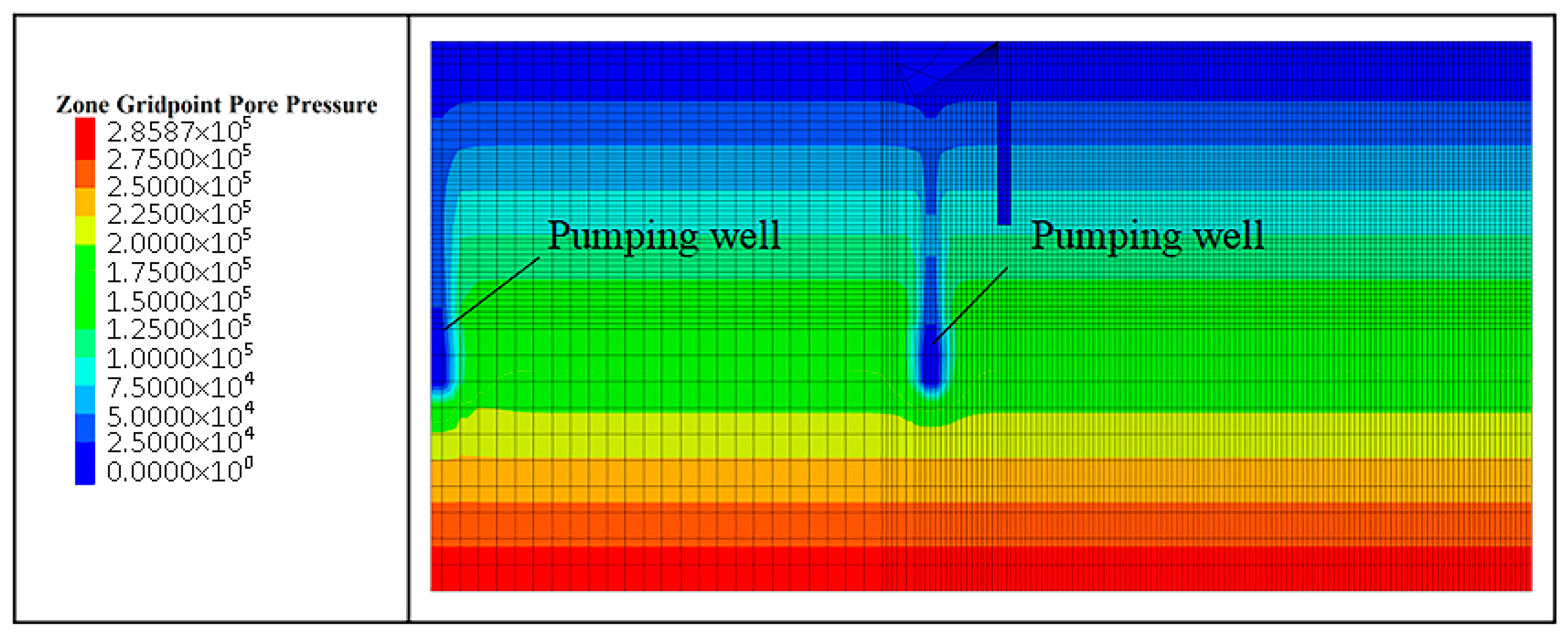
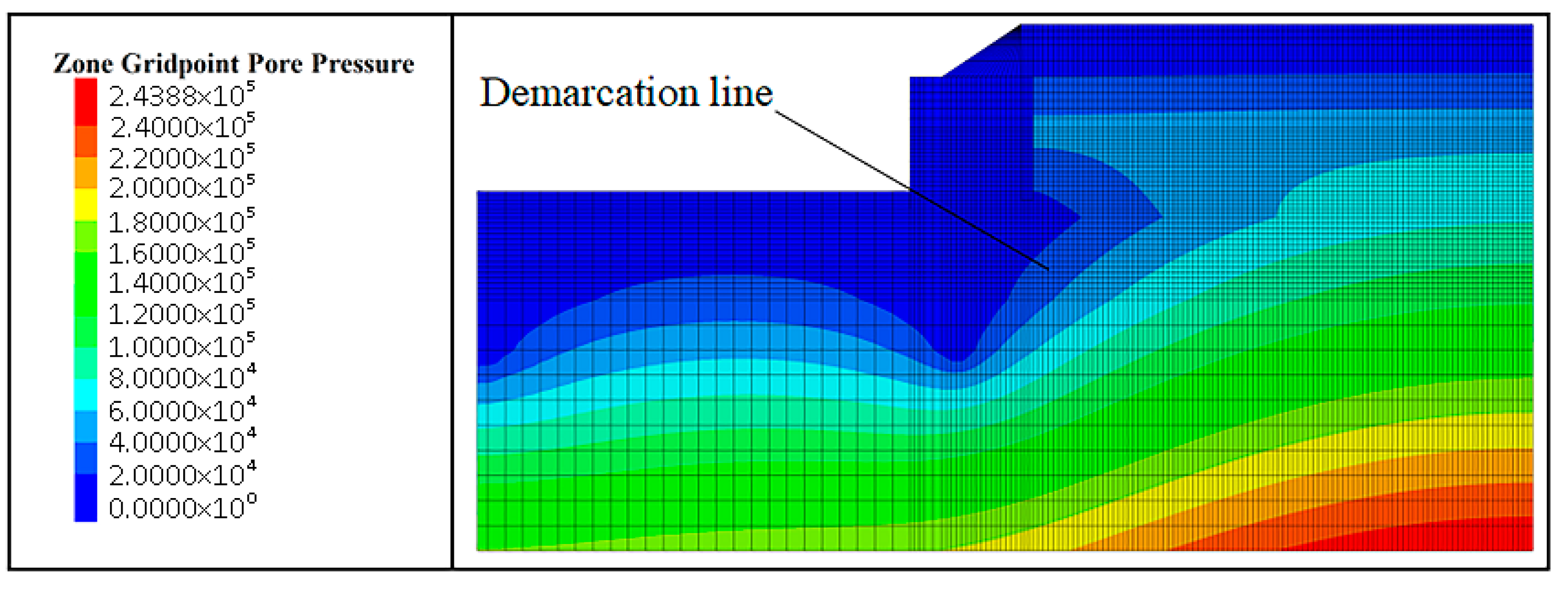
| 1 | Fluid–structure coupling | Pumping wells and drainage wells with depths of 18 m were set at x = 2 m and x = −25 m, respectively. In the range of 3–4 m depth, some soils were in the waterproof layer. Un-drained water was simulated by zone GRIDPOINT fix pore pressure 0 command. |
| 2 | Mechanical calculation | Slope was down while excavating to 3 m below the ground level. |
| 3 | Mechanical calculation | Construction of support pile, water-stop curtain, and top beam. |
| 4 | Fluid–structure coupling | Pumping wells continue to pump water, and open drainage treatment was carried out within the depth of 4.8–5.8 m. |
| 5 | Mechanical calculation | Excavation to 4.8 m below ground level. |
| 6 | Mechanical calculation | At a depth of 4.3 m, the lumbar girder and anchor cable were constructed and prestressed. |
| 7 | Fluid–structure coupling | Pumping wells continued to pump water, and the depth was within the range of 7.8–8.8 m. Open drainage treatment was carried out. |
| 8 | Mechanical calculation | Excavation to 7.8 m below ground level. |
| 9 | Mechanical calculation | At a depth of 7.3 m, the lumbar girder and anchor cable were constructed and prestressed. |
| 10 | Fluid–structure coupling | Pumping wells continued to pump water, and the depth was within the range of 9.52–10.52 m. Open drainage treatment was carried out. |
| 11 | Mechanical calculation | Excavation to 9.52 m below ground level. |
Publisher’s Note: MDPI stays neutral with regard to jurisdictional claims in published maps and institutional affiliations. |
© 2022 by the authors. Licensee MDPI, Basel, Switzerland. This article is an open access article distributed under the terms and conditions of the Creative Commons Attribution (CC BY) license (https://creativecommons.org/licenses/by/4.0/).
Share and Cite
Wu, C.; Kong, L.; Guo, Q.; Cao, H. Enlarged Head Pressure-Dispersed Anchor Cable for Foundation Pit Engineering Purposes. Appl. Sci. 2022, 12, 12400. https://doi.org/10.3390/app122312400
Wu C, Kong L, Guo Q, Cao H. Enlarged Head Pressure-Dispersed Anchor Cable for Foundation Pit Engineering Purposes. Applied Sciences. 2022; 12(23):12400. https://doi.org/10.3390/app122312400
Chicago/Turabian StyleWu, Chongfu, Linghe Kong, Quanwei Guo, and Haiying Cao. 2022. "Enlarged Head Pressure-Dispersed Anchor Cable for Foundation Pit Engineering Purposes" Applied Sciences 12, no. 23: 12400. https://doi.org/10.3390/app122312400
APA StyleWu, C., Kong, L., Guo, Q., & Cao, H. (2022). Enlarged Head Pressure-Dispersed Anchor Cable for Foundation Pit Engineering Purposes. Applied Sciences, 12(23), 12400. https://doi.org/10.3390/app122312400


