Abstract
During the rock-breaking process, severe vibration frequently leads to cutter system failures. The traditional cutter system is complicated in structure, and the cutter-changing operation is highly dependent on the manual operation, resulting in a low construction efficiency and a high risk. Thus, this paper designed an integrated cutter system with a simple structure, which lays a theoretical foundation for popularizing the cutter-changing robot. In the statics performance experiment, we built an integrated cutter system finite element model, calculated the stress value under a nominal load; manufactured the scaled cutter system based on the similarity principle, obtained the measured stress value through the load experiment; and verified the accuracy of this cutter system’s finite element model. In the dynamics experiment, we calculated the cutter system and each components dynamic response based on the concentrated mass method and the Newmark method, obtained the measured vertical vibration displacement through a scaled loading experiment and verified the correctness of the vertical dynamics model, and set the real disc cutter linear cutting load as the external excitation to verify the feasibility of the new cutter system design scheme.
1. Introduction
The disc cutter bears a great alternating load in the tunnel boring machine (TBM) rock-breaking process. The violent vibration causes the failure of the cutter system fastener and high consumption of the cutter, which requires monitoring and replacement frequently. It is challenging to improve the tunneling efficiency [1,2]. At the same time, the cutter replacement process is highly dependent on the manual operation; various safety hazards often threaten the life and safety of operators [3]. Therefore, it is imperative to use the robot to replace the manual cutter detection and replacement operation.
Factors such as the complex structure and multiple disassembly and assembly operation steps of the traditional cutter system restrict the cutter-changing actions, which makes the cutter-changing robot difficult to popularize and use. Some universities and companies first optimized the structure based on traditional industrial robots to achieve an automatic cutter replacement [4,5]. However, this scheme is difficult to apply due to the limitation of operational space and the load ratio of industrial robots in TBMs. Therefore, researchers try to design a new structure of cutter changing robots. Based on the KUKA’s 6-DOF industrial manipulator, the Bouygues Group [6] developed a cutter changing robot for the shield machine, designed a new cutter holder, and developed the corresponding end-effector. Huo [7,8] et al. of Dalian University of Technology proposed a 6-DOF cutter-changing robot and carried out a cutter-changing range analysis, joint trajectory planning, and motion control simulation. In addition, a hybrid curve trajectory planning method based on the trapezoidal velocity curve and quintic polynomial curve was proposed, and a variable structure PID controller based on dynamic model compensation was designed.
Universities and companies also try to improve the cutter system design scheme. In 2015, French companies BOUYGUES [9] combined with companies NFM proposed a connecting rod cutter system, which has simple disassembly actions, but it is easy to be stuck in the movement process and has a low reliability. In 2018, the Robot Innovation Center of the German Artificial Intelligence Research and Development Center [10] developed a slider cutter system, which has a simple structure and less disassembly actions, but it is hard to manufacture. Two French researchers, Derycke Jean-Noel and Rubrecht Sebastien [11], invented an integrated rotating-panel TBM cutter system, which has a simple structure and few disassembly actions, but has disadvantages such as excessive stress on the rotating panel and easy sticking of the rotating panel.
The study of the cutting cutter system in China started late. In 2018, Hongrun Construction Co., Ltd. [4] cooperated with universities to develop an integrated cutter system that uses an eccentric circular mechanism to lock the cutter. The cutter can be locked and unlocked by grasping the cutter counterclockwise, but it is difficult for the cutter-changing robot to grasp accurately. Meng [12] et al. of Dalian University of Technology proposed an integrated cutter system based on the topological structure theory of the planar mechanism, and the solution space is obtained for the six-bar single-DoF, which further improves the anti-loosening effect.
In summary, the research on the integrated cutter system has achieved certain results. However, there are still shortcomings, mainly reflected in the number of disassembly steps, locking capacity, and cutter system reliability. Based on the above research results, aiming at simplifying the cutter system structure and reducing the disassembly and assembly steps, this paper innovatively proposes an integrated new TBM cutter system design scheme.
2. Mechanical Performance Experiment of New TBM Integrated Cutter System
2.1. Structure Design of New TBM Cutter System
Traditional TBM cutter system mainly has three types: double wedge blocks cutter system, upper and lower wedge blocks cutter system, and rear-installed cutter system. The main structure defect of the above traditional cutter system is a complex structure and has numerous parts. The disc cutter disassembly steps are complicated, which will significantly reduce the disc cutter replacement efficiency.
This paper obtains inspiration from the automatic firearm’s mechanism and optimizes the traditional cutter system’s structure. We obtain a sliding block swing mechanism and evolve it into a fastening mechanism. Supplementing the cutter holder, high-strength bolts, disc cutter, wedge, shift fork, cutter side panels, and other components can get the complete design scheme of the wedge swing type new cutter system, as shown in Figure 1.
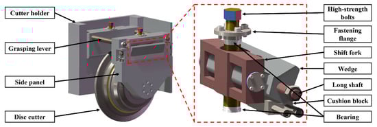
Figure 1.
Schematic diagram of wedge swing type cutter system.
The cutter system can be divided into the fastening module and supporting module according to the function. The main function of the fastening module is to fix the disc cutter tightly in the cutter system to ensure that it can reliably carry out a rock-breaking operation, and the main components are high-strength bolts, long shaft, shift fork, wedge, cushion block, fastening flange, etc. The main function of the support module is to limit the relative position between the cutter system’s two sides and provide a gripper for the operator or the cutter-changing robot when replacing the disc cutter. The main components are the grasping lever, side panels, cutter holder, cutter fixing bolts, etc.
The cutter system installation process begins when the operator or the cutter-changing robot places the entire cutter system into the cutter holder by holding the grasping lever. Just rotate the high-strength bolt and drive the shift fork to move up. At this time, the wedge will swing in the direction of the cutter holder side panel around the long axis, and the wedge top will extend into the groove inside the cutter holder to limit the displacement.
Conversely, when the cutter system needs to be removed, just rotate the high-strength bolt in the opposite direction and drive the shift fork to move down. At this time, the wedge will swing in the direction of the disc cutter around the long axis and the wedge top will leave the groove inside the cutter holder. So that the operator or the cutter-changing robot can lift the entire cutter system from the cutter holder through the grasping lever.
The core advantage of the new TBM integrated cutter system is that it simplifies and integrates the structure of the cutter system, greatly reduces the operation steps, improves the disc cutter replacement efficiency, and provides the possibility for the cutter-changing robot popularization. The disassembly performance comparison between the new and the traditional cutter system is shown in Table 1.

Table 1.
Disassembly performance comparison of various cutter systems.
At the same time, the overall weight of the new TBM integrated cutter system is significantly reduced compared with the traditional cutter system because of the emphasis on the lightweight design at the beginning of the design process (the total weight of the new cutter system is only 354.4 kg, which is significantly less than that of the traditional cutter system). The smaller weight is helpful for the operation of the operator or the cutter-change robot, which can improve the construction efficiency.
2.2. Finite Element Stress Calculation of New TBM Integrated Cutter System
The stress distribution rule of the cutter system under a nominal load can be obtained by using the finite element simulation calculation before the statics loading experiment. For the stress concentration part, the actual stress value can be measured by the statics loading experiment to verify the finite element calculation results.
In the finite element simulation process, a proper mesh size can form a balance between the computing efficiency, storage space, and calculation accuracy. Therefore, the finite element mesh convergence analysis of the cutter system should be carried out firstly to obtain the optimal mesh size.
After calculating and comparing the cutter system stress values under 5 groups of different mesh sizes (20 mm, 10 mm, 7 mm, 5 mm, and 3 mm), it is found that the stress values can obtain the highest stability and maintain a high precision under a 5 mm mesh size. Therefore, the finite element mesh size of the entire cutter system was set as 5 mm.
Take the real TBM working condition as an example, the disc cutter’s nominal load is a 315 KN vertical load, a 31.5 KN rolling load, and a 47.25 KN lateral load. However, the vertical load is obviously greater than the load in the other two directions (more than one order of magnitude). In the real rock-breaking process, the vertical load is the most important load which the disc cutter borne. Therefore, in order to simplify the calculation process, this paper ignored the rolling load and lateral load and instead just applied the vertical load (315 kN) to the model for the calculation of the finite element.
According to the assembly relationship between the TBM cutter head and cutter system, the holder is set as completely fixed in the finite element model, and the disc cutter and fastening devices are fixed as a whole part. Contact is set between the disc cutter shaft and the side panel circular groove surface, and the friction coefficient of this surface is set as 0.1.
Apply the nominal load to the disc cutter blade and start the finite element simulation. On this basis, we set other groups of different value loads and applied them to the finite element model in turn. The finite element model rationality can be verified by comparing the maximum stress position under different load values.
We calculate the cutter system’s stress by using finite element software. According to the results, the cutter system’s calculated maximum stress 131.92 MPa occurs at the apex of the shift fork, at point Max, shown in Figure 2.
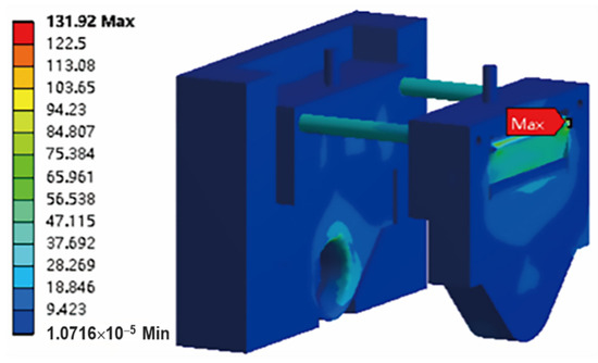
Figure 2.
The maximum stress value of cutter system.
2.3. Similarity Theory and Scaled Cutter System
In equipment development and testing, prototypes are often scaled down to obtain similar models for various performance tests. The similarity model has the advantages of a low cost, short test cycle, and an ease to control, which helps form the empirical formula quickly [13,14]. We carried out statics and dynamic experiments on the new TBM cutter system based on the similarity theory in this paper.
The establishment of similar structural parameters and quality attributes between the scaled cutter system and the prototype cutter system is a prerequisite for accurately simulating the real working conditions and loading of the TBM cutter system [15]. Therefore, select the similar parameters of the TBM prototype cutter system as follows:
- (a)
- Structural parameters: the side length l of a single cutter holder.
- (b)
- Physical properties: material density ρ, Poisson’s ratio μ, and elastic modulus E.
Based on the dimensional analysis method, and comprehensively considering the performance requirements and manufacturing costs of the scaled cutter system, as well as the structure and working range of the test bench, the similarity ratio of the cutter system’s structural parameters is formulated as 1:4. Since the materials used in the machining the scaled tool system are the same as those of a real TBM cutter system, the elastic modulus E similarity ratio in the material characteristic quantity is CE = 1, Poisson’s ratio similarity ratio is Cμ = 1, and the density similarity ratio is Cρ = 1.
Combining the Buckingham theorem, the similar constants of the related physical quantities of the scaled cutter system are shown in Table 2.
Table 2.
Similarity constant of physical quantity of scale cutter system.
Table 2 shows a square relationship between the loading force F and the side length l of the cutter system. Therefore, the loading force F should be scaled according to the square of the scale ratio, that is, 1:16. Since the nominal load of the real size disc cutter is 315 KN, the equivalent load applied to the scaled cutter system in the loading test is 19.69 KN.
2.4. The Scheme Design of Scaled Loading Experiment
In this scaled loading experiment, arrange the strain sensors on the cutter system’s key positions and apply the equivalent load to the scaled cutter system, which can obtain the measured stress values of the cutter system. The accuracy of the finite element model can be verified by the error between the calculated and measured stress values.
According to the finite element stress calculation results, the stress will concentrate in two points when the nominal load is applied to the cutter system: one point is the wedge top that contacts the cutter holder inside the groove, another is the circular groove top on the side panel that contacts the cutter shaft. Therefore, this paper takes these two points as the key positions for the stress measurement.
To reduce the error and avoid the negative impact of the accuracy which is caused by the strain sensor quality, this experiment arranges the strain sensors symmetrically on the left and right sides of the cutter system. Strain sensors #1, #2, and #5 are used to measure the stress at two key positions on the cutter system’s left side, and strain sensors #3, #4, and #6 are on the right side. Finally, the stress data of the left and right sides are compared with each other to verify the accuracy.
Considering the arrangement operability, strain sensors #1 and #2 are arranged in the plane area around the wedge top of the cutter system’s left side to simultaneously measure the stress value and are used as the comparison verification to reduce the error. Strain sensors #3 and #4 are arranged in the same way. At the same time, strain sensors #5 and #6 are arranged, respectively, at circular grooves at the top of the left and right side of the cutter system’s panels to simultaneously measure the stress value. A detailed sensor arrange schematic diagram is shown as Figure 3a.
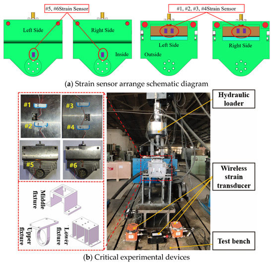
Figure 3.
Schematic diagram of scaled loading experiment.
The critical experimental devices in this statics performance experiment mainly include a test bench, wireless strain sensors, fixtures, and a hydraulic loader, shown in Figure 3b. The fixtures are used to limit the cutter system’s displacement, which divides into upper, middle, and lower parts. Wireless strain sensors are used to collect the strain data. To maximize the accuracy, arrange the strain gauges on six key points, and set 4 sets of load values, specifically 5 kN, 10 kN, 15 kN, and 20 kN.
The critical experimental devices used in this experiment are as follows:
(1) A hydraulic servo actuator; (2) a control system; (3) two computers; (4) a wireless gateway; (5) four strain test nodes; (6) and testing software. Part of the experimental test instruments is shown in Figure 4.
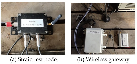
Figure 4.
Part of the critical experimental devices.
2.5. Processing and Analysis of Experimental Data
The statics performance experiment has obtained the strain value ε on the measured key points of the cutter system, and the elastic modulus E of the cutter holder material is known, so that stress value σ can be converted by Equation (1).
Strain data are collected 12 times, respectively. The average strain value ε is obtained after processing, and then we plugged it into Equation (1) to obtain the average stress value σ of the two parts, which can be compared with the finite element calculation results.
We applied the load to the scaled cutter system separately according to 4 sets of the load values, collected the strain values of the six strain sensors 10 times, and the average values at each sensor in each loading. The maximum error between the measured and calculated stress is 8.35% through comparison and calculation. Thus, the accuracy of the finite element model and the static properties of the new cutter system is proved.
3. Multi-DoF Coupled Dynamic Model of New TBM Integrated Cutter System
Due to a complex structure and connection relations, and the difficulty in predicting the vibration characteristics of the cutter system, it often leads to abnormal damage, deformation, and other faults to disc cutters and their holders [16,17]. The load will cause significant damage to the cutter body and holder’s fastening bolts, even the whole cutter system [18].
To build an accurate multi-DoF coupled dynamic model of the TBM new cutter system, establish an equivalent dynamic model based on the concentrated mass method, obtain the dynamic equation, and calculate the effective stiffness and damping of each node through the formula method and finite element method.
3.1. Equivalent Dynamic Model of New Integrated TBM Cutter System
Since the reaction force loss on the cutter ring in the transmission process of the cutter ring-cutter body-bearing-shaft is negligible, this section studies the disc cutter and holder’s vibration characteristics based on the concentrated mass method. The cutter ring, bearing, cutter body and cutter shaft are equivalented to one mass point, the two cutter side panels are equivalented to two mass points, the two ears are equivalented to two mass points, and the two shift forks are equivalented to two mass points, and the cutter holder wall panel is equivalented to two mass points. Considering the stiffness and damping of the parts simultaneously, establish a multi-DoF coupled cutter system vibration model, and its dynamic equivalent model is shown in Figure 5.
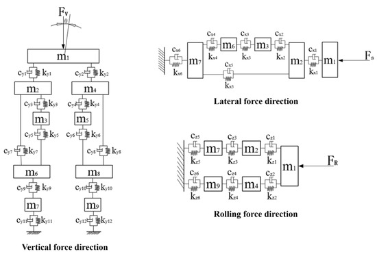
Figure 5.
Equivalent dynamic model of new integrated cutter system.
3.2. Dynamic Differential Equations of Vibration System
In this section, the dynamic differential equation of the cutter system will be established based on the equivalent dynamic model. The dynamic differential equation of each component of the cutter system can be expressed by Equation (2):
where [M], [C], and [K] are the mass, damping, and stiffness matrices, which can be obtained by the concentrated mass method, empirical formula, and finite element calculation, respectively.
This cutter system has 20-DoF. Establish a dynamic equation by means of the concentrated mass method and Newton’s second law in this section. According to the balanced relationship between the inertia force, elastic deformation force, damping force, and external excitation, establish the dynamic differential equations of each part in a vertical, lateral, rolling, and swing direction successively, and obtain the dynamic differential equations of this cutter system after a simultaneous establishment.
- 1.
- Vertical direction
- 2.
- Lateral direction
- 3.
- Rolling direction
- 4.
- Swing direction
In the above four equations, mi is the equivalent mass of each mass block, where m1 is the equivalent mass of the disk cutter; m2 and m4 are the equivalent mass of the left and right side panel, respectively; m6 and m8 are the equivalent mass of the left and right side of the wedge, respectively; m3 and m5 are the equivalent mass of the left and right shift forks and high strength bolts (bolts and shift forks can be regarded as a whole particle through thread connection), respectively; and m7 and m9 are the equivalent mass of the left and right inside of cutter holder, respectively.
yi (i = 1, 2, 3, 4, 5, 6, 7, 8, 9) is the displacement of the mass block in a vertical direction;
xi (i = 1, 2, 3, 6, 7) is the displacement of the mass block in a lateral direction;
zi (i = 1, 2, 4, 7, 9) is the displacement of the mass block in a rolling direction;
kyi (i = 1, 2, 3, 4, 5, 6, 7, 8, 9, 10, 11, 12) is equivalent stiffness of the mass block in a vertical direction;
kxi (i = 1, 2, 3, 4, 5, 6) is the equivalent stiffness of the mass block in a lateral direction;
kzi (i = 1, 2, 3, 4, 5, 6) is the equivalent stiffness of the mass block in a rolling direction;
cyi (i = 1, 2, 3, 4, 5, 6, 7, 8, 9, 10, 11, 12) is the equivalent damping of the mass block in a vertical direction;
cxi (i = 1, 2, 3, 4, 5, 6) is the equivalent damping of the mass block in a lateral direction;
czi (i = 1, 2, 3, 4, 5, 6) is the equivalent damping of the mass block in a rolling direction;
θ1 is the swing angle of the cutter ring;
J is the rotational inertia in the rolling direction of the disc cutter.
3.3. Structural Dynamic Parameters of the Vibration Model
The 19-inch disc cutter, the most widely used in engineering, is used for the modeling. The cutter’s bearing greatly influences the overall stiffness, so it cannot be solved simply as a single node. Therefore, the cutter is divided into three nodes: the cutter body Z1, the bearing Z2, and the cutter shaft Z3, and then calculate the stiffness, respectively. Then, the overall stiffness of the cutter is equivalent by series.
3.3.1. Equivalent Mass of the Cutter System Components
This section obtained the equivalent mass of each node by using SolidWorks software based on the above dynamic differential equations, as shown in Table 3.
Table 3.
Nodes equivalent mass of cutter system components.
3.3.2. Equivalent Stiffness of the Cutter System Components
This section mainly studies the vibration characteristics of the TBM new cutter system, and the components which have the greatest influence on the cutter system will be regarded as a whole, such as a cutter ring, bearing, and cutter shaft. The other components’ influence is too small to be ignored. The stiffness of the W1 cutter body can obtain the stiffness of the whole cutter, the W2 bearing (including the bearing outer ring and bearing half roller), and the W3 cutter shaft (including the cutter shaft and bearing the inner ring) in series.
The stiffness k of the whole disc cutter can be expressed in Equation (7):
This section uses equations to calculate the stiffness of W2, and uses the FEA method to calculate the stiffness of W1 and W3, considering the low accuracy in using equations to calculate the nonstandard parts.
- (1)
- Equivalent stiffness of node W1
Fix the cutter body’s internal surface, apply a vertical load and lateral load, respectively, on the cutter ring in finite element software, and calculate the cutter body’s deformation results as shown in Figure 6. From the definition of the stiffness and FEA method, the equivalent radial stiffness kyW1 and axial stiffness kxW1 of node W1 can be obtained as Equations (8) and (9):
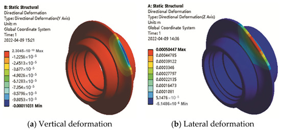
Figure 6.
Calculated deformation results of the cutter ring.
- (2)
- Equivalent stiffness of node W2
The bearing is a standard part, and the equivalent radial stiffness kyW2 and axial stiffness kxW2 of node W2 can be obtained by Equations (10) and (11):
- (3)
- Equivalent stiffness of node W3
Fix both ends of the cutter shaft and apply a vertical load during the vertical deformation analysis. Since the lateral load will transfer to the cutter shaft through the end cover, fix the cutter shaft through the side with no end cover and apply the lateral load to the side near the end cover; the calculated deformation results of the cutter body are shown in Figure 7. From the definition of the stiffness and FEA method, the equivalent radial stiffness kyW3 and axial stiffness kxW3 of node W3 can be obtained as Equations (12) and (13):
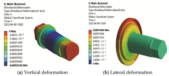
Figure 7.
Calculated deformation results of the cutter shaft.
The vertical and lateral equivalent stiffness of the cutter at node m1 can be obtained as Equations (14) and (15):
The rolling direction equivalent stiffness of the cutter at node m1 can be obtained as Equation (16):
The equivalent stiffness of other nodes can be calculated by using the above method, as shown in Table 4, Table 5 and Table 6.
Table 4.
Vertical direction equivalent stiffness of each node.
Table 5.
Lateral direction equivalent stiffness of each node.
Table 6.
Rolling direction equivalent stiffness of each node.
3.3.3. Equivalent Damping of the Cutter System Components
This section uses equations to calculate the damping of W2, and uses the empirical formula in the mechanical design manual to calculate the stiffness of W1 and W3, which is shown as Equation (17):
In Equation (17), c is the damping of the structural parts and ξ is the damping ratio. In the elastic stage of the steel structure, ξ is generally 0.02~0.05, so we set it to 0.02 in this paper. me and ke are the equivalent mass and equivalent stiffness of each component, respectively.
- (1)
- Equivalent damping of node W1
The equivalent radial damping cyW1 and axial damping cxW1 of node W1 can be obtained as Equations (18) and (19):
- (2)
- Equivalent damping of node W2
The equivalent radial damping kyW2 and axial damping cxW2 of node W2 can be obtained as Equations (20) and (21):
- (3)
- Equivalent damping of node W3
The equivalent radial damping cyW3 and axial damping cxW3 of node W3 can be obtained as Equations (22) and (23):
The vertical and lateral equivalent damping of the cutter at node m1 can be obtained as Equations (24) and (25):
The rolling direction equivalent damping of the cutter at node m1 can be obtained as Equation (26):
Table 7.
Vertical direction equivalent damping of each node.
Table 8.
Lateral direction equivalent damping of each node.
Table 9.
Rolling direction equivalent damping of each node.
During the rock-breaking process, the cutter will be subjected to the lateral force due to the rotation of the cutterhead and the squeezing of the blade on the rock, resulting in a torsional pendulum vibration along the Y-axis. The calculation equation for the overturning damping is shown as Equation (27):
where cbr is the radial damping of the bearing, l1 and l2 are the distances from the left and right bearing outer ring to the center of the cutter shaft, respectively, and their lengths are both 0.0375 m. Finally, the cθ value is 246.53 Nm2/s.
4. Dynamic Characteristics Analysis of New TBM Integrated Cutter System
This chapter will study the dynamic characteristics and load transfer rule of each component of the new TBM cutter system, based on the regular sinusoidal load as the external excitation. To analyze the vibration response rule, use the Newmark method as the main calculation method, meanwhile combine the equivalent stiffness and damping of each component. Calculate the theoretical vertical vibration displacement of the scaled cutter system based on similarity theory, measure the actual vertical vibration displacement through the load experiment, set the actual cutter load obtained from the linear cutting experiment as the external excitation, and study the more realistic vibration response of each component of the cutter system, which ensures that the cutter system can work well under real rock-breaking conditions.
4.1. Vibration Response Solution of Cutter System
4.1.1. Numerical Solution of Differential Equations
There are two main methods for solving dynamic differential equations: the analytical method and numerical method. The analytical method gives the exact solution of the equation. However, the existence of the initial value makes the solution process harder and more complicated when solving the cutter system’s dynamic response. The numerical method obtains the approximate solution of the equation. It is easier to program and solve, even though it is less accurate than the analytical method. Currently, the numerical methods for solving dynamic differential equations mainly include Euler, Newmark, Runge-kutta, Gill, etc. [19,20]. The Newmark method is a direct integration method mainly used to solve the structural dynamic response. It has the characteristics of a fast solving speed and a high accuracy [21]. This section uses the Newmark method to solve the cutter system’s dynamic equation and obtain each component’s time-domain dynamic response.
When α and β, which are the control parameters in the Newmark numerical method, are equal to 0.5 and 0.25, the solution is unconditionally stable and is not affected by the time step Δt. Combined with the dynamic differential equation of the cutter system, the solution process based on the Newmark method is shown in Figure 8.
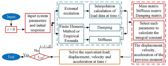
Figure 8.
Dynamic response solving process based on Newmark method.
4.1.2. Vibration Response of Each Component
Set the cutters’ nominal load as the mean value of external sinusoidal excitation, set the excitation’s vibration frequency as 5 Hz, and set the vibration amplitude as 25% of the mean value, based on the actual cutters’ impact load. Solve the cutter system’s each component vibration displacement response through the Newmark method, as shown in Figure 9.
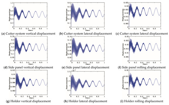
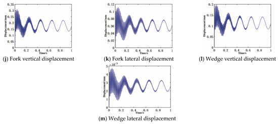
Figure 9.
Vibration displacement response curve of each structural components.
The vibration displacement response curve of the disc cutter and holder’s each mass block shows that:
- (1)
- The new cutter system’s each component response will oscillate in the initial loading stage. In this stage, each component acceleration changes dramatically under the load action, which leads to the reduction in the system’s stability. Under the common influence of internal and external excitation, each component vibration displacement response is the same as that of external load excitation, and the vibration displacement response changes sinusoidal after the stability.
- (2)
- Order the mean value and amplitude of each component vibration displacement. In the vertical direction: cutter system > disc cutter side panel > shift fork > wedge > cutter holder; in the lateral direction: cutter system > disc cutter side panel > shift fork > wedge > cutter holder; and in the rolling direction: cutter system > cutter side panel > cutter holder. The above shows that each component vibration amplitude decreases gradually along the force transmission direction. Therefore, in the design process, those parts that are prone to failure due to the vibration influence should be placed as far back as possible.
- (3)
- Order the mean value and amplitude of most of the components’ vibration displacement in different directions: vertical direction > lateral direction > rolling direction, which is caused by the order: vertical load > lateral load > rolling load. The rock-breaking process is mainly carried out by a vertical load, which is one order of magnitude higher than the lateral and rolling load. Therefore, the vertical direction should have a high stiffness during the cutter system design, to ensure the system’s reliability in the rock-breaking process.
4.2. Scaled Vibration Experiment of Cutter System
To measure the vibration displacement of the cutter structure’s key components under the vertical low-frequency load, carry out a vibration characteristic experiment through a dynamic hydraulic loading device in this section to verify the dynamic model’s accuracy.
To avoid the influence of different sample machining errors on the measured data, the vibration loading experiment and the statics experiment use the same scaled cutter system and fixture.
4.2.1. Vibration Loading Experiment Scheme Design
- (1)
- Critical experimental devices
Figure 10a shows the critical devices of the vibration loading experiment. Number one is the Keyence high-precision displacement sensor (LK-G405), it can measure the displacement of the key points; number two is a laptop computer for the data collection; number three is the processing display for converting the laser pulse signal into the displacement data and displaying it in real-time; number four is a tripod, used to adjust the position and angle of the sensor; and number five is the gantry hydraulic actuator test bench for providing the vibration loads. The overall measurement scheme is shown in Figure 10b.
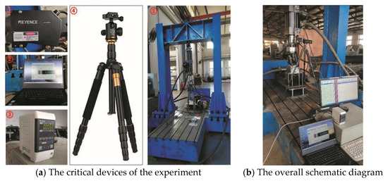
Figure 10.
Critical experimental devices of vibration loading experiment.
- (2)
- Experimental scheme
Fix the scaled cutter system on the test bench, clamp the laser displacement sensor, and adjust the distance between the sensor and measured points to 400 mm.
To improve the vibration displacement measurement accuracy, the measured points should be selected reasonably. Set the point C on the upper fixture’s upper surface, as the cutter is directly connected to the upper fixture through bolts; set the point D on the lower surface in the rectangular groove on the middle of the cutter system’s side panel; and set the point E on the upper surface of the test bench, to eliminate the interference of the test bench vibration to the cutter and holder, which is shown in Figure 11.
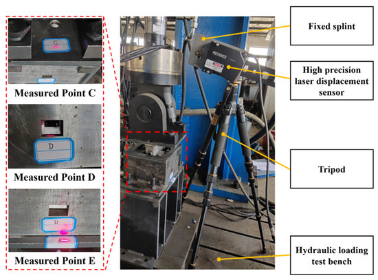
Figure 11.
Scheme diagram of vibration loading experiment.
According to the schematic design, the experimental steps are as follows: start the laser displacement sensor and irradiate the laser spot on the measured points; start the hydraulic loader and apply the load (average load is 19.6 kN, vibration amplitude is ±20%, frequency is 5 Hz). Use the computer and processing monitor to record the displacement and vibration load data.
4.2.2. Experimental Results and Comparative Analysis
It is necessary to collect the vibration average value and vibration amplitude data of the 10 cycles, to reduce the measurement error. Use dC, dD, and dE to represent the vertical vibration displacements on point C, point D, and point E. The test bench can also vibrate under external excitation and the vertical displacement of point E can be subtracted from point C and point D to eliminate the influence of test bench vibration. Use d(C–E) and d(D–E) to represent the vertical vibration displacement relative to the earth. Detailed displacement data are shown in Figure 12 and Table 10. It can be concluded that the relative errors between the measured and theory average vertical displacement values are 9.99% on point C and 5.18% on point D, which can verify the vertical dynamic model’s accuracy.
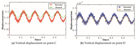
Figure 12.
Measured and theoretical vertical displacement on point C and D.
Table 10.
Vibration displacement data of measured points.
4.3. Dynamic Response of Cutter System Based on Measured Load
Use the actual cutter load obtained from the previous linear cutting experiment as the external excitation to obtain a more real cutter system dynamic response rule of each internal component during the rock-breaking process. The critical experimental devices are shown in Figure 13. The vertical hydraulic cylinder presses the cutter against the rock with great pressure. Meanwhile, the test bench moves horizontally under the horizontal hydraulic cylinder action. Collect the load data in real-time during the rock-breaking process with a triaxial force transducer, which is shown in Figure 14.
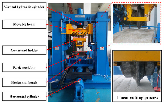
Figure 13.
Critical devices of cutter linear cutting experiment.
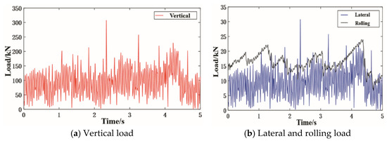
Figure 14.
Measured triaxial load data of cutter linear cutting experiment.
Use the Newmark method to solve each component’s vertical, lateral, and rolling vibration displacement responses under the above external excitation, shown in Figure 15 and Table 11. The root mean square (RMS) value and amplitude of the components’ vibration displacement decrease along the force transmission path, the maximum value is less than 1 mm, and both appear in the vertical direction. This proves that the disc cutter mainly relies on the vertical impact load to break the rock, and it is necessary to increase the cutter ring’s surface hardness through the heat treatment operation.
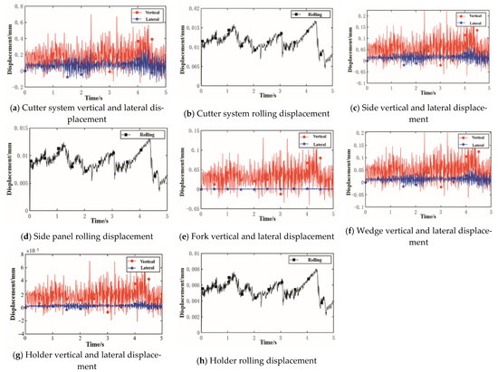
Figure 15.
Calculated vibration displacement responses of each component.
Table 11.
Displacement response of each component of the system under measured load.
5. Conclusions
In this paper, a new TBM integrated cutter system with a simple structure and few disassembly steps is designed, which lays a theoretical foundation for the TBM cutter-changing robot popularization.
- (1)
- In this paper, the statics performance experiment is carried out first. The finite element method is used to calculate the new cutter system stress distribution under the nominal load, and different values of the load are applied to calculate the position of the maximum stress point, so as to verify the accuracy of the finite element model. A new scaled cutter system is manufactured based on the similarity theory, and the statics performance experiment is carried out. It is found that the relative error between the calculated stress values and the measured stress values is less than 10%, which further verified the accuracy of the finite element model.
- (2)
- Then, the dynamic characteristics is analyzed. The multi-DoF equivalent mechanical model of the new cutter system and the dynamic differential equations in each direction are established by the concentrated mass method. The vibration response of each cutter system component is solved by the Newmark method. The vibration test of the scale sample is carried out based on the hydraulic loading test bench. It is found that the relative error between the theoretical mean value of the vertical vibration displacement and what is measured is less than 10%, which verifies the correctness of the vertical dynamics model which is established. The real load in the disc cutter linear cutting experiment is used as the external excitation to analyze the dynamic response of each component. The maximum vibration RMS and amplitude of the system are 0.2300 mm and 0.7003 mm, respectively. Additionally, the feasibility of the new cutter system’s design scheme during the real rock breaking process is verified finally.
Author Contributions
Funding acquisition, J.H.; project administration, J.H.; validation, F.Y.; writing—original draft, F.Y. and T.L.; methodology, T.L.; writing—review and editing, Y.S.; investigation, H.C. All authors have read and agreed to the published version of the manuscript.
Funding
This work was supported by the National Natural Science Foundation of China (Grant No. 51875076) and the National key R & D plan of China (Grant No. 2018YFB1306701).
Institutional Review Board Statement
Not applicable.
Informed Consent Statement
Not applicable.
Data Availability Statement
The data presented in this study are available on request from the authors.
Conflicts of Interest
The authors declare no conflict of interest.
References
- Huo, J.; Sun, W.; Chen, J. Optimal disc cutters plane layout design of the full-face rock tunnel boring machine (tbm) based on a multi-objective genetic algorithm. J. Mech. Sci. Technol. 2010, 24, 521–528. [Google Scholar] [CrossRef]
- Espallargas, N.; Jakobsen, P.; Langmaack, L. Influence of Corrosion on the Abrasion of Cutter Steels Used in TBM Tunnelling. Rock. Mech. Rock. Eng. 2015, 48, 261–275. [Google Scholar] [CrossRef]
- Copur, H.; Cinar, M.; Okten, G. A case study on the methane explosion in the excavation chamber of an EPB-TBM and lessons learnt including some recent accidents. Tunn. Undergr. Space Technol. 2012, 27, 159–167. [Google Scholar] [CrossRef]
- Yuan, J.; Guan, R.; Du, J. Design and Implementation of Disc Cutter Changing Robot for Tunnel Boring Machine (TBM). In Proceedings of the 2019 IEEE International Conference on Robotics and Biomimetics (ROBIO), Dali, China, 6–8 December 2019; pp. 2402–2407. [Google Scholar]
- Huo, J.; Wang, W.; Sun, W. The multi-stage rock fragmentation load prediction model of tunnel boring machine cutter group based on dense core theory. Int. J. Adv. Manuf. Technol. 2016, 90, 277–289. [Google Scholar] [CrossRef]
- Mansard, N.; Khatib, O.; Kheddar, A. A Unified Approach to Integrate Unilateral Constraints in the Stack of Tasks. IEEE T Robot. 2009, 25, 670–685. [Google Scholar] [CrossRef]
- Zhang, H.; Huang, L.; Huo, J. Design and Motion Control of Disc Cutter Changing Robot for TBM. J. Basic Sci. Eng. 2021, 29, 1234–1244. [Google Scholar]
- Zhang, H.; Meng, Z.; Guo, Z. Motion Control of Disc Cutter Changing Robot Body for Tunnel Boring Machine. In Proceedings of the 2021 IEEE Asia-Pacific Conference on Image Processing, Electronics and Computers (IPEC), Dalian, China, 14–16 April 2021. [Google Scholar]
- Schwob, A.; Guedon, F.; Combe, B. Tuen Mun–Chek Lap Kok Link in Hong Kong–Innovative solutions for construction of an outstanding Subsea Tunnel. In Engineering and Innovation meet Archaeology Architecture and Art; CRC Press: Boca Raton, FL, USA, 2021. [Google Scholar]
- Simi, A.; Manacorda, G. The NeTTUN Project: Design of a GPR Antenna for a TBM. In Proceedings of the 2016 16th International Conference on Ground Penetrating Radar (Gpr), Hong Kong, China, 13–16 June 2016; pp. 1–6. [Google Scholar]
- Derycke, J.; Rubrecht, S. Method for Replacing a Tunnel Boring Machine Disk Cutter, Handling Device and Disk Cutter Suited to Such a Method. US20130045055 A1, 30 August 2016. [Google Scholar]
- Meng, Z.; Yang, D.; Huo, J. Development and Performance Evaluation of an Integrated Disc Cutter System for TBMs. Appl. Sci. 2021, 11, 644. [Google Scholar] [CrossRef]
- Huo, J.; Li, G.; Wu, H. Design of a TBM cutterhead reduced-scale test bench and its static/dynamic characteristics analysis. J. Harbin Eng. Univ. 2016, 37, 713. [Google Scholar]
- Chen, Z.; Chen, G. Research of Dynamics Response Based on Similarity Theory and Model Test. J. Vib. Meas. Diagn. 2014, 34, 995–1000. [Google Scholar]
- Luo, Z. Review and Prospect for Dynamic Similitude Theory and its Applications in the Structure Vibration. J. Mech. Eng. 2016, 52, 114. [Google Scholar] [CrossRef]
- Pezeshky, P.; Sahraei, A.; Rong, F. Generalization of the Vlasov theory for lateral torsional buckling analysis of built-up monosymmetric assemblies. Eng. Struct. 2020, 221, 111055. [Google Scholar] [CrossRef]
- Sahraei, A.; Pezeshky, P.; Mohareb, M. Simplified expressions for elastic lateral torsional buckling of wooden beams. Eng. Struct. 2018, 174, 229–241. [Google Scholar] [CrossRef]
- Lin, Y.; Nie, Z.; Ma, H. Mechanism of Principal Component Analysis in Structural Dynamics under Ambient Excitation. Int. J. Struct. Stab. Dy. 2020, 20, 2050136. [Google Scholar] [CrossRef]
- Mitchell, L.; David, J. Proposed Solution Methodology for the Dynamically Coupled, Nonlinear Geared Rotor Mechanics Equations. ASME J. Vib. Acoust. 1985, 107, 112–116. [Google Scholar] [CrossRef]
- Yang, D.; Sun, Z. A Rotary Model for Spur Gear Dynamics. J. Mech. Transm T Asme. 1985, 107, 529–535. [Google Scholar] [CrossRef]
- Kortis, J.; Daniel, L. Application of the Newmark numerical method with contact algorithm to the solution of the vehicle-bridge interaction. Procedia Eng. 2016, 153, 298–303. [Google Scholar] [CrossRef]
Publisher’s Note: MDPI stays neutral with regard to jurisdictional claims in published maps and institutional affiliations. |
© 2022 by the authors. Licensee MDPI, Basel, Switzerland. This article is an open access article distributed under the terms and conditions of the Creative Commons Attribution (CC BY) license (https://creativecommons.org/licenses/by/4.0/).