1. Introduction
Many conventional techniques applied in nondestructive testing are based on an active mode, in which testing loadings are applied during testing to deliver signals or energy from the outside to the test body. In contrast, the acoustic emission (AE) technique is a passive method that does not require the application of external energy to the test structure, as AE is generated by a material as a result of a sudden release of energy (other than heat) from localized sources within the solid, in turn due to a failure of lattice vibrations in materials. AE sources are usually classified as primary or secondary. Primary AE sources include material degradations related to deformation and fracture development, whereas leak, flow, and the fabrication process are secondary AE sources. Due to this unique characteristic, AE techniques are uniquely applicable to structure health monitoring (SHM) [
1,
2,
3,
4].
Among the primary AE sources, crack formation and growth are the most important practical nondestructive testing (NDT) because the detecting and monitoring of these failures can prevent or slow further damage. Thus, in SHM, the point source (PS) is adapted as an AE excitation source; for example in seismic displacements, crack fracture and cleavage, and concentrated vertical step forces [
5,
6,
7,
8,
9,
10]. The displacements generated by a PS were first introduced by Stokes [
11]. Later, Achenbach presented mathematical formulas for displacements in spherical geometry by defining it as a concentrated force (CF) loaded at a point [
12]. In mathematical formulas, Helmholtz potentials for the displacements were derived in terms of scalar potentials generated by PS excitation in an infinite domain [
12,
13,
14]. Although the AE generated by the PS is important for characterizing real signals observed in practical SHM, theoretical modeling was limited to spherical geometries in an infinite domain. To our knowledge, no theoretical work on AE excited by an internal PS in cylindrical geometries was reported in the literature. Most theoretical works on elastic wave properties in cylindrical geometries focused only on wave propagation and scattering situations with or without external perturbations [
15,
16,
17,
18,
19,
20,
21,
22,
23].
In linear elastodynamics, the Navier–Lamé (NL) equation is the most popular and effective method for solving the displacement fields in elastic media. In cylindrical coordinates, the NL equation was solved by combining three potentials responsible for one compression (P) wave and two shear waves (horizontally and vertically polarized; SH and SV, respectively), using the models proposed by Morse and Feshbach [
24] and Buchwald [
25], respectively. The basic difference between the two models is that the compression and shear parts are separated in one of them, but not the other. The two models were examined comprehensively for the case with no body forces by Honarvar et al. [
15,
18] and Sakhr et al. [
20,
21]. Additionally, Shatalov et al. developed a method to find exact solutions for axisymmetric wave propagation in functional cylinders by matching continuity and boundary conditions at layer junctions [
26,
27].
Previously, we constructed the NL equation specifically for displacements generated by PS excitation in a transversely isotropic cylinder (TIC) [
28] and a two-dimensional plate [
29]. As an internal defect, the CF acting in a preferent direction had both spatial and temporal properties, represented by the delta function and time-dependent CF vector. As the first task, Green’s function for the delta function was determined in a given geometry. Green’s function contributes the CF distribution in a given domain. For TIC, the CF vector contributes to the temporal Helmholtz potentials for P, SV, and SH waves based on the Morse and Feshbach model. Contrary to ordinary potentials, these potentials are characterized by the nature of the material defect. For discriminating from ordinary ones, these potentials are referred to as CF-incorporated potentials (CFIPs), which reduce the original scalar components of the NL equation into three independent partial differential equations (PDEs) for P, SV, and SH waves. The exact solution was solved and applied to the P, SV, and SH displacement simulations.
The main purpose of this work is to present a completeness theorem applicable to AE due to CF excitation in circular cylindrical geometries, including shell and rod configurations. In Ref. [
28], we confined the displacement solutions with a 2π-periodic (azimuthally free) angular part in the tangential component. We reconstructed the displacement solutions by applying a fundamental set of free-surface conditions on outer and/or inner circumferences and 2π-aperiodicity with azimuthal functions. Absolute values of the displacement fields were calculated at a given point on the outer surface, in which two modes of the CF along the radial and axial directions were considered. To our knowledge, the proposed method is the only one in the literature that is fully applicable to cylindrical geometries. The analytical modeling presented in this paper provides insight into the overall AE signal process from generation and propagation to reception. We offer a systematic and unifying solution method that can be used to evaluate the AE signal generated from an internal crack in a cylindrical structure.
2. Green’s Function
In Ref. [
28], the CF as the internal PS located at
is formulated in terms of an oscillating impulse with natural frequencies of the material in a given geometry, as follows:
where
P is the force vector and
ω is the predominant angular frequency
of AE. Dirac’s delta function
provides a method for solving spatial problems dealing with a PS. Green’s function
, defined as
Is the solution for the delta function in elastodynamics, and provides the spatial distribution of the CF at a given time. In cylindrical coordinates, Equation (2) is expressed as
where
is the Laplacian in cylindrical coordinates, and the CF is located at
, and
. At any point in the cylindrical domain except the CF locating point, Equation (3) becomes zero,
In cylindrical
coordinates, Equation (4) can be rewritten as
Substituting the following relations
Into the above PDE results, we obtain
Note that we selected exponential, rather than oscillating, solutions in the z-direction. This implies that the radial solutions are appropriate for the particular set of boundary conditions under consideration. In ref. [
28], we obtained the axial, tangential, and radial components of Green’s function under certain conditions, such as the continuity and discontinuity principles, angular symmetry for the cylindrical domain with length
l and a radius of
a. The inner radius
b is introduced to the shell structure as an additional radial boundary condition.
In Equation (7),
is a Bessel function of the first kind of
v-th order. The Bessel function of the second kind is excluded because there is no singularity in the cylindrical domain. The value of
can be obtained by applying the boundary conditions at the outer or inner surfaces of the cylindrical shell to Equation (7):
As an alternative, the boundary condition
was applied [
30]. However, this condition resulted in a discontinuous and asymmetric Green’s function. Selecting the first root (
) of the Bessel function,
or
. These relations give
For the outer surface,
. Introducing a parameter,
Aν1, we obtain Green’s function:
In ref. [
28], the parameter
was determined by integrating the delta function in the cylindrical domain. The integrations of
for the cylindrical shell are the same as those for the cylinder, because these two delta functions are independent of
r. The remaining problem is to integrate
,
Multiplying both sides of Equation (10) by
and integrating over
gives the following:
The integrations on the left side of the above equation can be divided into two parts:
Applying the normalization and orthogonality principles of Bessel functions,
And the following concepts of the delta function,
To Equation (11), we obtain the constant
For the cylindrical problem, the corrected value of
is given in (A1). Introducing Equation (12) to Equation (9) gives the Green’s function for the Kronecker delta function:
where
Since the CF direction is determined by the
P vector, Green’s function is assumed to be azimuthally independent (
v = 0). In addition, it is very convenient to take the location of the PS as the new origin and introduce relative coordinates to the location of the PS, defined as
,
, and
, where
,
, and
(hereafter, referred to as the PS-oriented
coordinate system), Equations (13) and (14) can be rewritten as
In Equation (15), the value of
at a given point is the shortest distance from the PS. In cylindrical geometry,
For the shell geometry, the calculation of
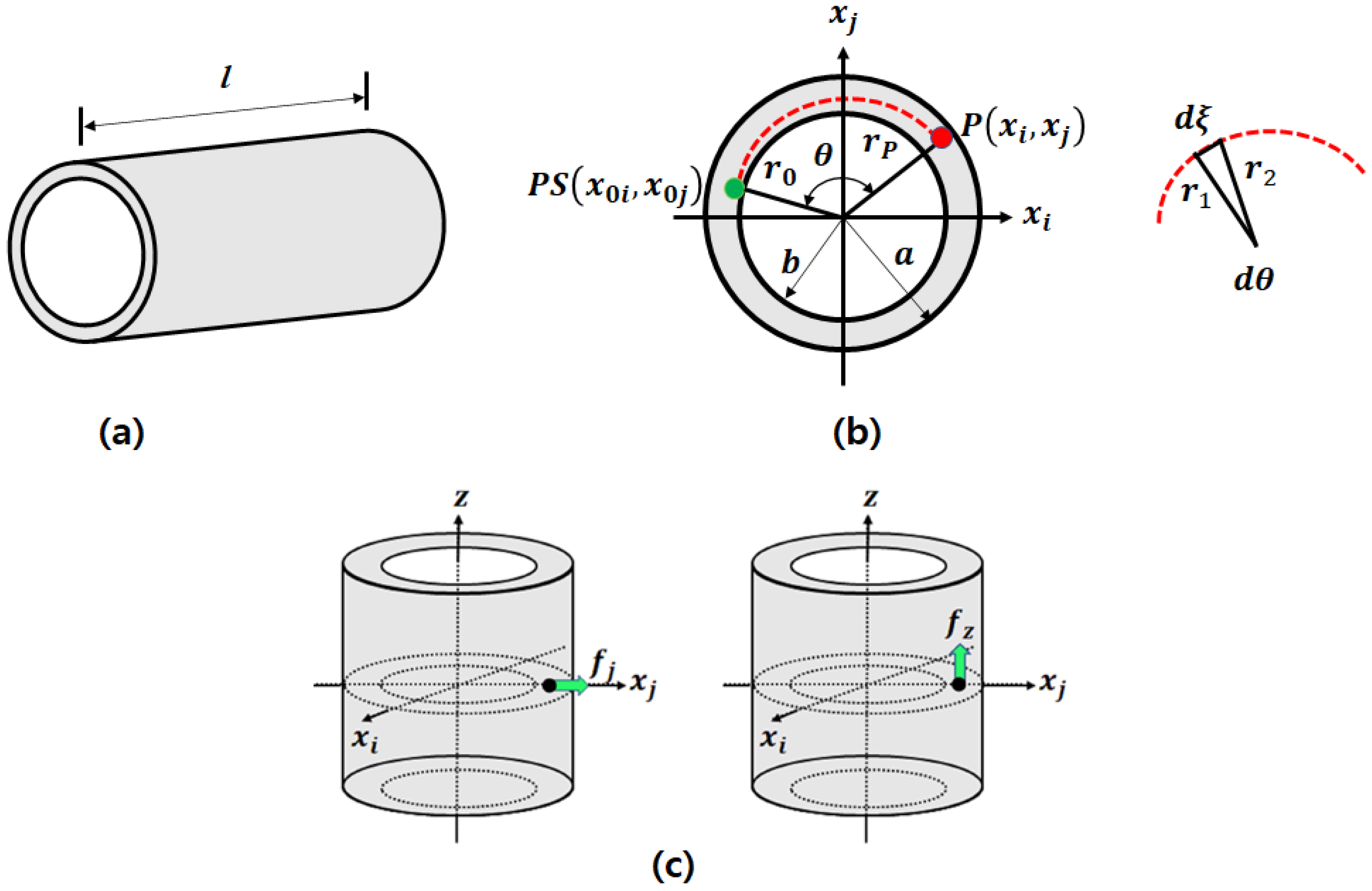
is somewhat complicated due to its hollow interior. No linear distance exists between the two points across the hollow interior. In
Figure 1b, an arc connecting the PS and a given point is introduced. This connection should not intersect with the hollow circle. The arc rises at a constant rate between
and (
<
), given as
, where
θ is the angle between the PS and a point P. If the angle,
, between
and
is infinitesimal, the arc length,
, connecting the two points, becomes a line. Applying the cosine rule to the triangle,
Assuming that
and
, the above equation becomes
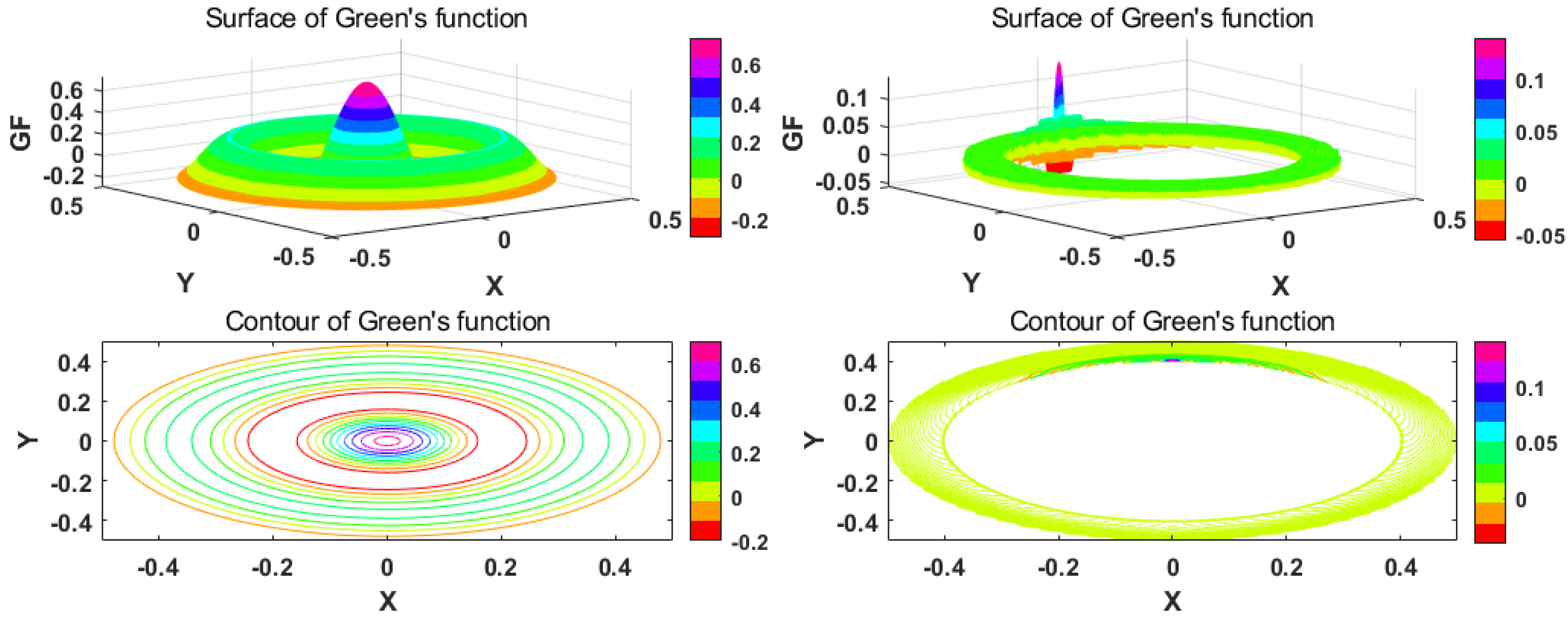
Figure 2 shows the Green’s function calculated for the cylinder (
a = 0.5 m,
b = 0) and shell (
a = 0.5 m,
b = 0.4 m). It can be shown that the calculated functions are continuous and symmetric with respect to the PS location.
3. Displacement Fields Generated by a Point Source
The NL equation for the displacement field
u in an elastic and homogeneous medium subject to a local body force
f is given by [
31]
where λ and μ are the Lamé constants, and
is the density of the media. The displacement field
u in cylindrical coordinates proposed by Morse and Freshbach involves three potential functions
for the P wave,
for the SH wave, and
for the SV wave. The representation of
u for cylindrical geometries is given by
where
a is the radius of the cylinder. For the displacement field generated by the force vector
P due to an intrinsic point defect, the three potential functions
,
, and
are correlated with the force vector
P (referred to as CFIPs). CFIPs in the PS-oriented
Cartesian coordinates are defined as
where
,
, and
are scalar functions for P, SH, and SV waves, respectively. These scalar functions are expressed by
Combining Equations (19)–(23) with Equations (1) and (2), and replacing the Lamé constants and
by the longitudinal wave speed
and transverse wave speed
leads to
where
and
, corresponding to the angular wavenumbers of the P and the S waves, respectively. The solutions of these PDEs in the PS-oriented
cylindrical coordinates are as follows:
where
and
. The corrections for the particular solutions in Ref. [
28] are given in
Appendix A.
In the same manner as in ref. [
28], the force vectors
Ps acting in the radial
and the axial
directions are introduced to solve for
, and
. By substituting Equation (27) into Equation (21) with coordination conversion, we obtain the CFIP for the P wave
In Equation (31),
where
is the angle between an observation point and the
axis. Similarly, we obtain the CFIP for the SH wave
where
The CFIP for the SV wave is given by
All three CFIPs for the P, SH, and SV waves were completely determined in the given CF direction. In ref. [
28], detailed derivation of the displacement components for the cylindrical geometry are described in terms of
,
, and
. For the cylindrical geometries, applying gradient, divergence, and curl operators, Equation (20) results in the displacement components in the
coordinates as
where
and
are the radial, tangential, and axial displacements, respectively. In the
coordinates, these displacement components are as follows:
Substituting Equations (30), (33), and (36) into Equations (38)–(40) gives the displacement
d component due to
Pj as
Notably, the component
(
f =
j or
z) is obtained from the particular solutions for P and SH potentials associated with Green’s function. In this paper, the components
in ref. [
28] is corrected.
For the radial component
,
For the tangential component
For the axial component
,
Similarly, the displacement
d due to
is expressed by
For the radial component
,
For the tangential component
,
For the axial component
,
As expressed by Equations (41) and (54), the displacement components involve the coupling constants
Am,
Bm, and
Cm. These constants can be determined directly by applying a fundamental set of linear elastic boundary problems. The outer and inner surfaces of the cylindrical shell studied in the present paper are stress-free. Thus, the following stress components are zero at
and
, satisfying
for the outer circumference and
for the inner circumference in Equation (17) for the shell
In ref. [
28], by using the stress displacement relations, we obtained a system of linear algebraic equations for the TIC, given by
where
f =
j for
Pj and
f =
z for
Pz.
For
, all elements in Equation (64) are nonzero, as given by
For
, by substituting Equations (77)–(85) into Equation (64), we derive
Equation (86) allows us to obtain the value of at a given point on the circumference.
The only remaining task to complete the displacement fields is to introduce retardation times into the CF
P in Equation (1). The CF is an impulsive force acting at the PS-oriented origin
, and
at
t = 0. The arrival time τ of the signal at position
must be considered. The arrival times of the P and S waves propagating with velocities
and
are given as
respectively, where
is given by Equation (18). Introducing
and
b parameters, determining the amplitude and duration of the wave, respectively, yields the CF acting in the
f direction as
In the simulation, 1.0 × 10¹⁰ N s−1 and b = 1.0 × 10⁻⁵ s−1.
Finally, the displacements generated by
Pf can be obtained as
For practical purposes, the P, SH, and SV waves are introduced as
4. Simulations
In ref. [
28], simulations of the displacement fields in TIC were confined to the case for the azimuthal independence (
) of wave propagation. In this paper, we extended the simulation to the case of azimuthally dependent tangential displacements, i.e., 2π-aperiodic solutions. Stainless steel cylindrical structures (
a = 0.50 m,
l = 2.0 m,
ρ = 7.80 × 10
3 kg/m
3,
km/s,
km/s, and ν = 155.4 kHz) were used as the test specimens. First, we determined
from Equation (86), resulting in two solutions of
.
On the outer circumference,
the first root of the function
Was solved at a given PS location as a function of
η (
) and the shortest distance
from the PS to a given point (0.5 m, 45°,
η) on the outer circumference of the cylindrical structures.
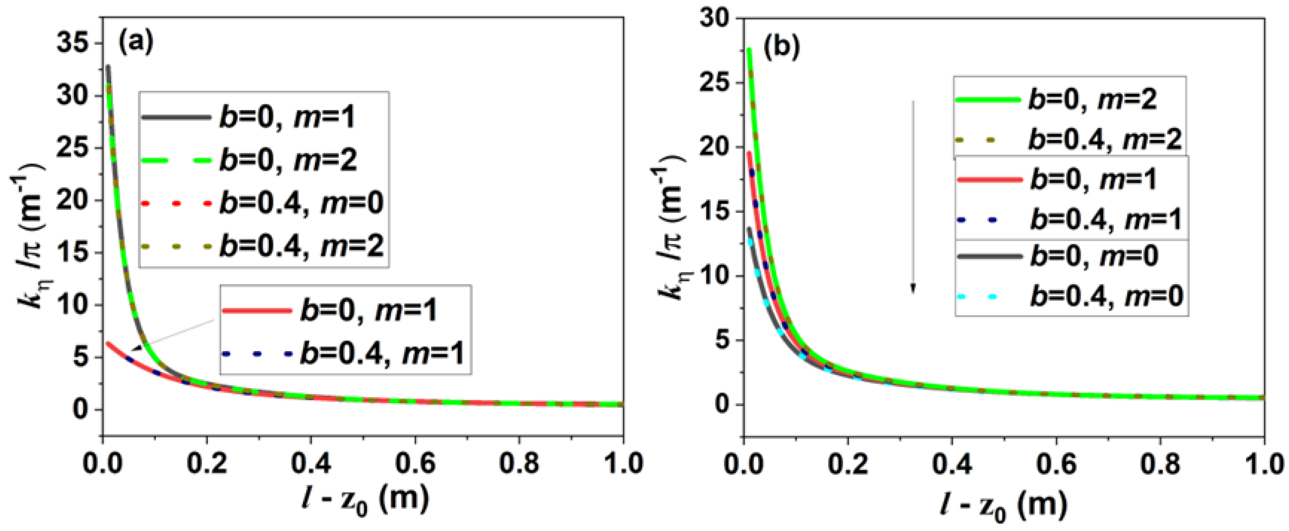
Figure 3 shows the dependence of
on
η for the cylinder (
b = 0) and shell (
b = 0.4 m). As shown in the figure, the
values are independent of the inner diameter
b. When PS is located on a radial axis, the dependence of the
η-dependency of
values is very simple: all values are divided into two groups with even
m and odd
m. It should be noted that the
values are almost independent of
.
Using these
results, we simulated the displacement fields at the outer surfaces of the cylinder (
b = 0 m) and cylindrical shell (
b = 0.4 m).
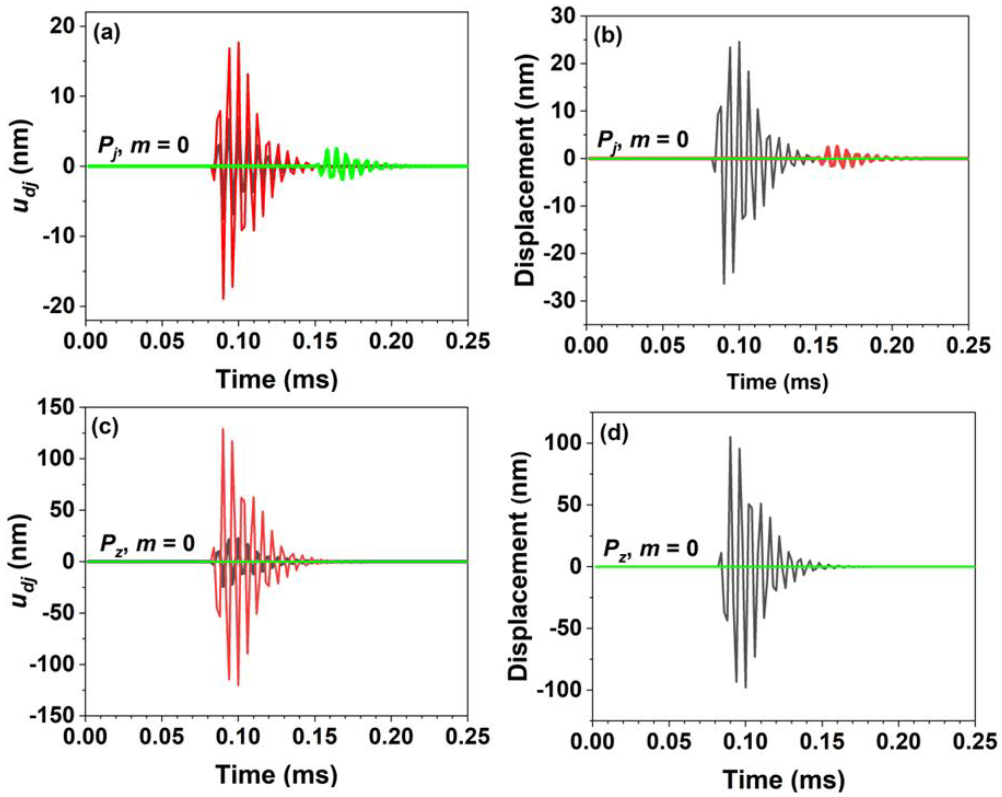
Figure 4 shows the 2π-periodic (
m = 0) displacements and their wave properties at the (0.5 m, 45°, 1 m) position, generated by the
PS located at the center of the cylinder
. The
Pj and
Pz excitations produce an axial displacement stronger than the radial and tangential displacements. For the
Pj excitation, the displacement results in the P wave are the main wave, with a minor SH wave and very weak SV wave. In
Figure 4, the displacement amplitudes generated by
Pz excitation differ significantly from those generated by the
Pj excitation, in which the
Pz excitation produces only the P wave. For the
Pj excitation, the maximum values of
and
at the (0.5 m, 45°, 1 m) position were 6.7 and 17.4 nm, respectively, while for the
Pz excitation they were 22.1 and 127.0 nm, respectively. The amplitudes of the displacements due to
Pz excitation are much stronger than those due to the
Pj excitation.
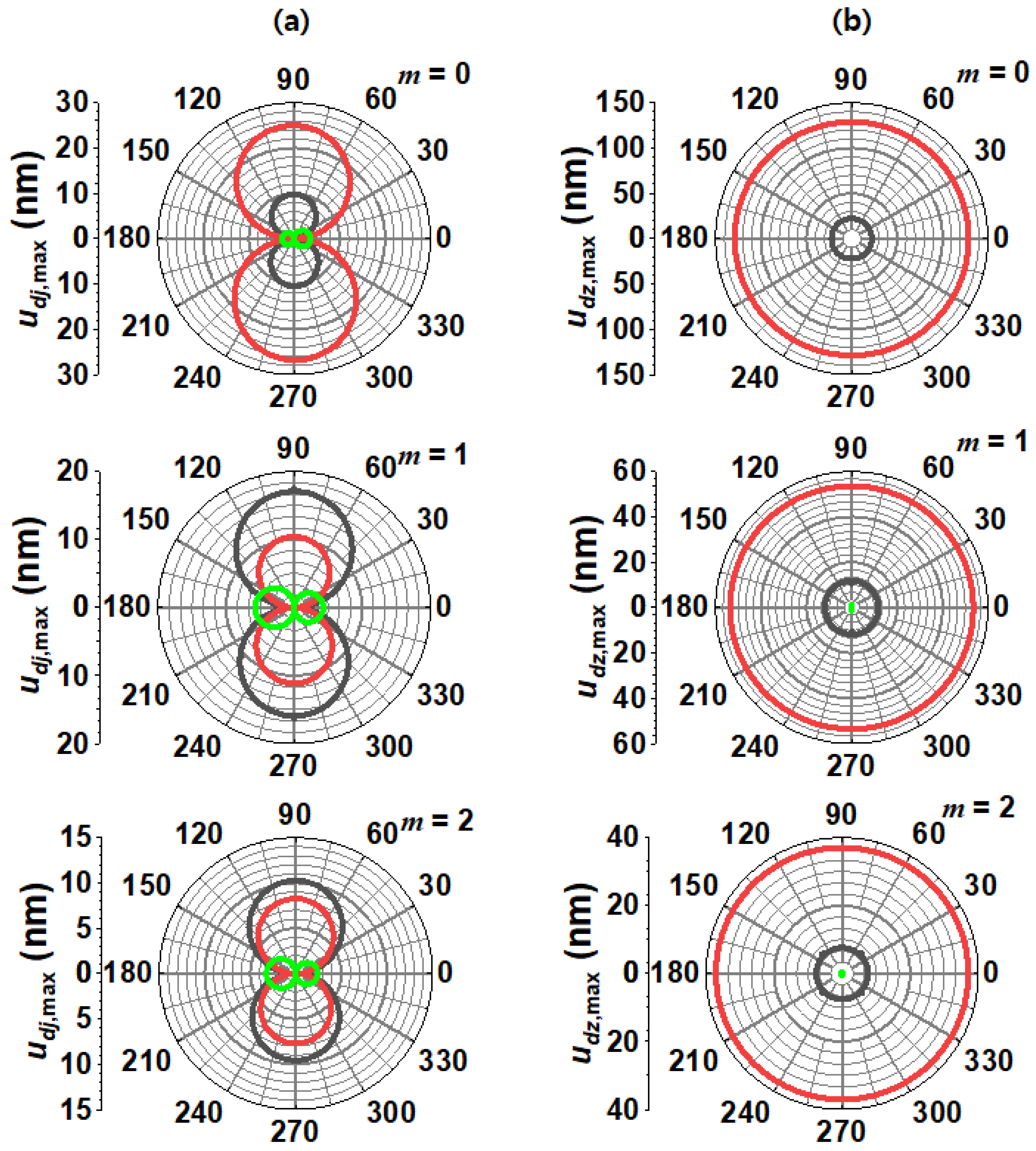
The angular dependence of the displacement was also calculated as a function of
m (
m = 0, 1, and 2), as shown in
Figure 5. For
m = 0, when the PS is located at the center of the circular plane, the angular dependences of
,
, and
arise only from Ξ and Σ, defined in Equations (32) and (35), respectively. For
Pz excitation, the displacements of
and
are free from these factors. When the distances from the PS to the circumference are not equivalent, the angular dependences of the radial and axial displacements are highly significant. These effects are due not only to Ξ and Σ, but also to the superposition of the Bessel functions involved in the displacement Equations. When
m is nonzero, additional azimuthal factors,
m,
, and
, result in complex angular dependency. It should be noted that at a certain angle, some
values of
, and
in Equation (64) become too small to cause the sudden increase in displacement, hereafter referred to as “computational divergency”.
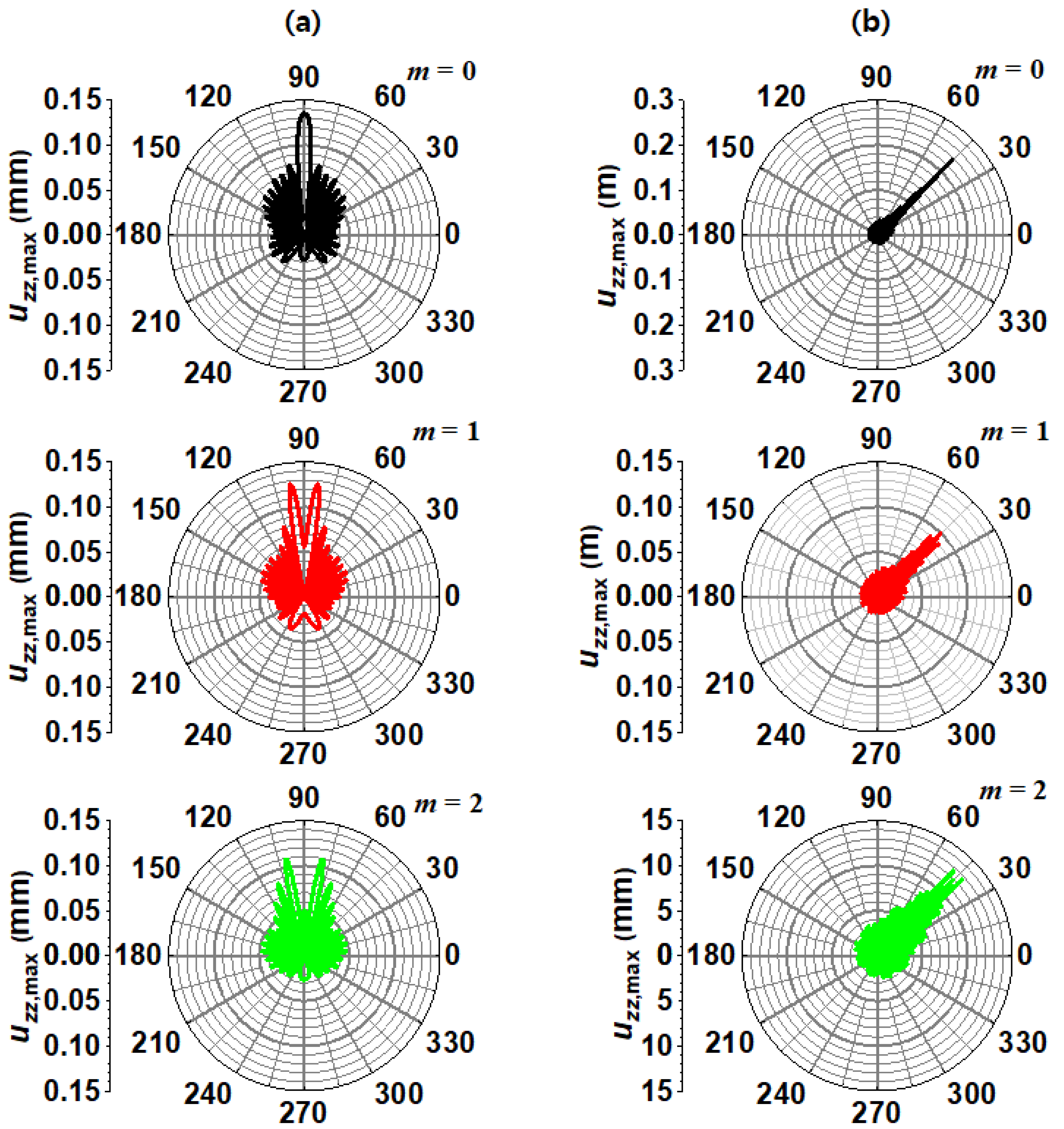
Figure 6 shows the angular dependence of a relatively strong
generated by two PSs located at
and
m, and
and
m. For the first PS, the distance from the PS to the point at
,
, and
on the outer surface is the shortest with
.
For this case,
. For the second PS, the distance along
is the shortest from PS
. Spectra of the angular dependences of the displacement fields are symmetric with respect to
. As shown in
Figure 6, the
displacements at a point very close to the PS
are extremely large. Remarkably,
Pz excitation of 1 N produces a P wave with a maximum amplitude of tens of centimeters.
Similarly, the displacement fields and their wave properties excited by the PS were also calculated as a function of
m (
m = 0, 1, and 2) for the shell (
a = 0.5 m,
b = 0.4 m).
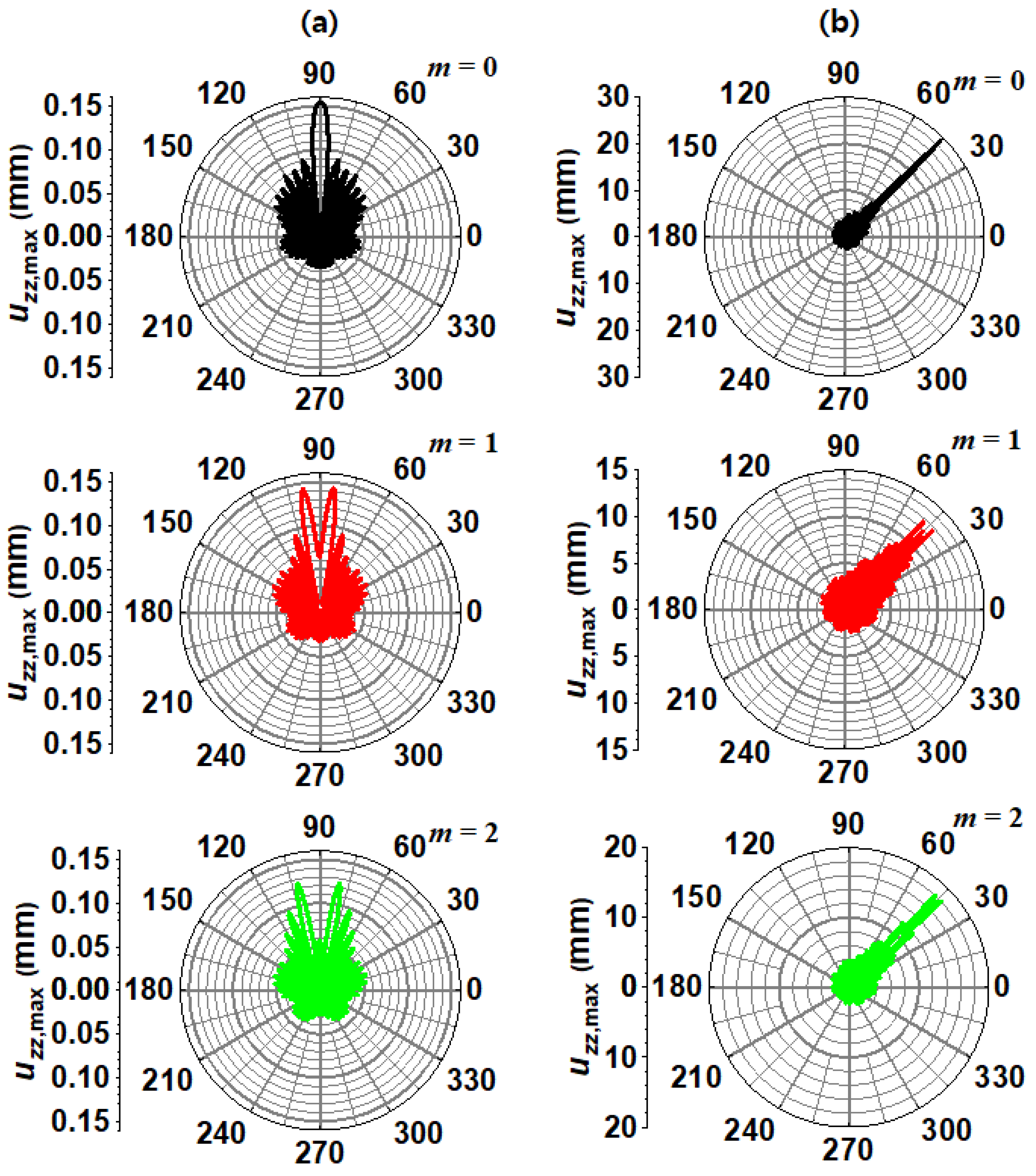
Figure 7 shows the angular dependences of the axial component
uzz generated by two PSs located at
and
m, and
and
m. There is no difference in the spectral features of the corresponding angular dependences between the cylinder and shell geometries. However, the maximum amplitudes of the shell are much smaller than those of the cylinder.
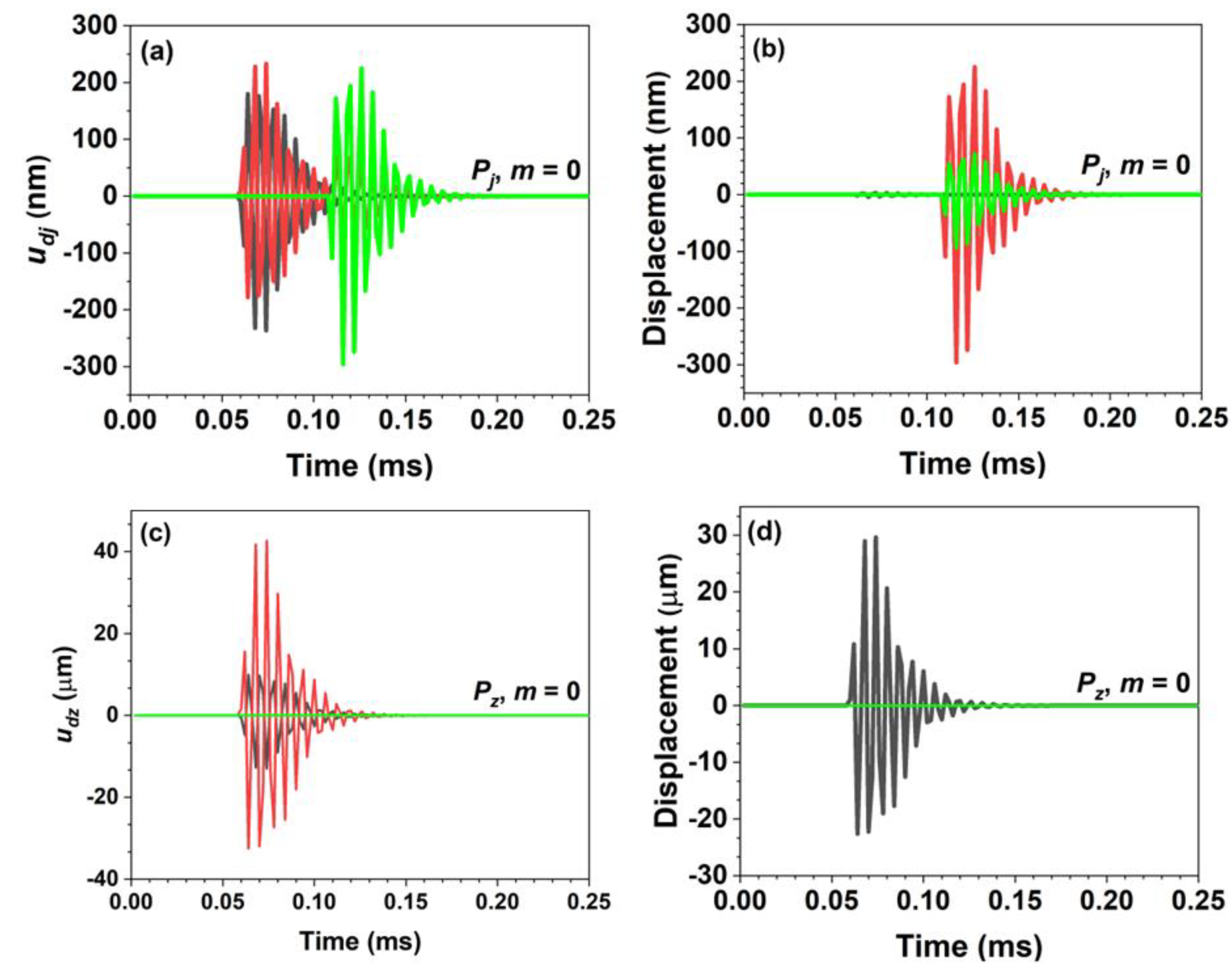
Figure 8 shows 2π-periodic (
m = 0) displacements at the (0.5 m, 45°, 1 m) position. For the shell, the most striking feature of the displacement fields is the tangential displacement
due to
Pj excitation, the amplitude of which is comparable to that of the axial displacement
, as shown in
Figure 8a.
