Article

Damage Detection in a Rotor Dynamic System by Monitoring Nonlinear Vibrations and Antiresonances of Higher Orders

by
Jean-Jacques Sinou
Laboratoire de Tribologie et Dynamique des Systèmes UMR CNRS 5513, École Centrale de Lyon, 36 Avenue Guy de Collongue, 69134 Écully, France
Appl. Sci. 2022, 12(23), 11904; https://doi.org/10.3390/app122311904
Submission received: 26 October 2022 / Revised: 7 November 2022 / Accepted: 18 November 2022 / Published: 22 November 2022
(This article belongs to the Section Acoustics and Vibrations)

Abstract

:
Since rotor systems are very sensitive and vulnerable to transverse crack, early detection of damage is of paramount importance and essential for rotating machinery. Therefore, one of the main issues is to identify robust characteristics of the rotor vibration response that can be directly attributed to the presence of a transverse crack in a rotating shaft, preferably when the crack is small enough, in order to avoid catastrophic failures of rotating machines. This study investigates the potential links between the nonlinear vibrations and the locations of higher-order antiresonances and structural modifications due to the presence of a breathing crack in rotor systems. Using the proposed numerical results on the evolution of the nonlinear responses of a cracked rotor system, it was observed that a robust diagnostic of the presence of slight damage can be conducted by tracking nonlinear vibrational measurements, with particular attention to the antiresonance behavior of higher orders. These observations can easily serve as target observations for the monitoring system and for identifying the positions of damage at an early stage.

1. Introduction

One of the most challenging problems in the vibration monitoring of rotating machines is to promote effective tools and robust indicators to detect damage at an early stage. Nowadays, rotating machines are designed to operate at increasingly higher efficiencies and under increasingly challenging operating conditions for structural system integrity. As a result, many rotating systems contain rotor shafts that are potentially highly susceptible to transverse fatigue cracks. Certain catastrophic failures of rotating machines are due to the presence of growing cracks in the rotor shaft. This primary accidental risk, which can lead to rotor system downtime and prohibitive economic costs, can be avoided by deploying the early detection of propagating cracks. Many efforts have been made in this field of structural health monitoring to better understand the impact of the presence of a transverse crack on the dynamic behavior of rotating systems, leading to the development of advanced detection of defects to ensure the safety of rotating machines during continuous operation and under potentially fluctuating loading conditions.
Generally, three different approaches are attempted to detect the presence of a crack in a rotating structure and possibly identify the position and size of the crack. The first approach is based on monitoring the natural frequencies of the rotor system because the presence of a crack in the rotating shaft reduces the rigidity of the rotor shaft, and therefore, causes a decrease in the natural frequencies of the original uncracked rotor system [1,2,3]. This approach has the advantage of being very easy to apply. It is often effective for detecting large faults but has the disadvantage of being incapable of detecting small ones. Consequently, this approach is very limited for the predictive maintenance of rotating systems in a real environment. The second approach focuses on changes in the linear measurements of the frequency response functions (FRF) and certain associated indicators, such as the motion of antiresonances [4,5,6,7] and coupling the vibration measurements of a rotating cracked shaft [8,9,10,11]. It can be noted, however, that some difficulties may arise when seeking a robust identification of damage based on the use of linear analysis: indeed, the crack might open and close alternately during experimental tests [12] due to the real and complex environments of rotating machines during operational conditions. If the presence of an open crack leads only to a loss of physical stiffness, which allows studying linear systems, the development of breathing cracks not only reduces the stiffness of the structure, but tends to make an otherwise linear structure non-linear, because of the evolution of the structure’s stiffness characteristics associated with open and closed states. Therefore, considering the fact that the presence of damage can induce more complicated behavior, an alternative approach is to take into account the influence of an active transverse crack in the response of a rotor model by investigating the nonlinear structural vibration responses. As mentioned previously, the concept of an active crack is represented by the opening and closing of the crack (also called the crack breathing phenomenon [13,14,15,16,17]). Thus, many works based on the tracking of nonlinear dynamic characteristics, such as the presence of n × harmonic components or changes in the rotor orbit shape with the occurrence of multi-loops, have been developed and tested by many researchers [18,19,20,21,22,23,24,25,26]. It is now generally recognized that the use of nonlinear analysis allows the efficient and robust detection of medium to large defects due to the fact that nonlinear dynamic characteristics are significantly influenced by the presence of a transverse breathing crack in the rotating shaft. Since it is not possible to give an exhaustive list of all the work of interest carried out on structural health monitoring and damage detection, the reader can refer to the various state-of-the-art papers that have been proposed in the past for crack detection based on the measurement of linear and nonlinear vibrations [27,28,29,30,31,32,33,34].
More recently, some studies have shown that the presence of uncertainties might cause classical linear and nonlinear approaches to be less robust for detecting small cracks [35,36,37,38,39,40,41]. In order to overcome this difficulty, recent works have suggested looking at the zeros of the higher-order frequency response function (HOFRF), i.e., the antiresonance frequencies of HOFRF, for the detection and location of small cracks in beam systems [42,43]. It can be noted that the use of antiresonances from linear measurements has rarely been considered in structural health monitoring [4,5,6,7], whereas the antiresonance frequencies of measured FRFs provide useful information on the dynamic properties of a mechanical structure [44] and can be used for robust model updating [45,46]. For linear systems, it is well known that the magnitude of the FRF is characterized by the resonance–antiresonance pattern in the frequency domain and the antiresonance behavior due to the relationship between the driving and measurement points of the mechanical system. Indeed, the resonance frequencies can be defined as global quantities whose values do not depend on the given driving point and chosen measurement point. On the contrary, the antiresonance frequencies are typical of each FRF and depend on the location of both the driving force and the measurement point. One of the most well-known results regarding resonance–antiresonance behavior is that the resonances and antiresonances alternate continuously only for FRFs where the excitation points and the measurement points coincide. In this context, this study proposes a preliminary analysis of the supplementary information that can be obtained from the antiresonances of the higher-order responses for structures with local nonlinearities. More specifically, it considers the potential of using the locations of these antiresonances for the detection and identification of damage in rotating machines. Indeed, when considering the nonlinear response of a rotor system with a breathing crack, antiresonances of higher orders could become an attractive alternative in structural damage assessments. Due to the fact that antiresonances are very sensitive to small structural changes, the use of antiresonances of nth orders (with n > 1 ) seems to potentially meet several requirements for early damage detection in rotating machines. In this paper, the aim is to achieve this objective by proposing a complete numerical study to examine the nonlinear responses and the tracking of the antiresonance frequencies of nth orders for different configurations of cracked rotors. This work continues from two previous works [42,43] that addressed the problem of crack detection in a pipeline beam by using the non-linear vibrations and the antiresonances of HOFRF. Here, we propose an extension of this approach to the problem of structural health monitoring for rotating machines.
This paper is organized as follows: A brief reminder of the general description and characteristics of the cracked rotor system under study is first presented. The second section presents the general formulation of predicting the dynamic responses of the cracked rotor system. Then, the most relevant results on the crack’s effect on the vibrational response of the rotor system are discussed. More specifically, the impact of the presence of a breathing crack on the vibrational response of the cracked rotor is analyzed, focusing more particularly on the appearance of harmonic components. The limitations of such detection by tracking nonlinear responses are also discussed in the context of robust preventive fault detection (i.e., structural health monitoring in the case of a rotor system with a small crack) in order to situate the objective and the originality of the study proposed. Finally, an efficient damage detection methodology based the antiresonance frequencies of higher orders is presented, and its robustness for crack localization, even when small levels of damage are encountered, is demonstrated by numerical examples.

2. Description of the Cracked Rotor System

This section briefly presents the modeling of the cracked element based on the notion of stiffness reduction and the breathing mechanism. The rotor system under study is also described. For the interested reader, the complete modeling of the rotor system was explained previously in [40], and the cracking model used in this study was proposed and discussed previously in [16].
The mechanical system under study consists of a two-bearing flexible cracked rotor, as shown in Figure 1. The system is composed of a shaft with a circular cross-section, 0.5 m in length and 0.01 m in diameter, with two rigid circular discs located at the middle of the shaft and at a quarter of the left side, respectively. The rotor is supported by two flexible supports, one on each extremity. It is excited by an out-of-balance force on both discs. The rotor shaft is discretized with 20 Euler beam elements, where each node has four degrees of freedom (dof). The values of the rotor parameters are given in Table 1.
Considering that the presence of one transverse crack induces local flexibility due to strain energy concentration in the vicinity of the tip of the crack under load [13,14], it can be assumed that the reduction in the second moment of area Δ I at the location of the crack is given by
Δ I = I 0 R l 1 ν 2 F μ 1 + R l 1 ν 2 F μ
where I 0 is the second moment of the area of the cross-section of the healthy rotor. R, l, and ν are the beam radius, element length of the section, and Poisson ratio, respectively. F μ defines a nonlinear compliance function which can be obtained from a series of experiments with chordal cracks [13,14]. μ = h R is the non-dimensional crack depth and h defines the depth of the crack, as illustrated in Figure 1. It then follows that the local flexibility due to the presence of one crack leads to an additional amount of stiffness denoted by K c r a c k at the crack. The complete expressions of the stiffness matrix K c r a c k are given in [16].
In addition, due to the rotation of the rotor system, it can be assumed that the crack will open and close once per revolution. The function describing this periodic opening and closing of the crack, called “breathing”, can be approximated by a cosine function g ( t ) [16], by assuming that the gravity force is much greater than the imbalance force (i.e., the cracked rotor rotates under the load of its own weight). This results in the expression of a simple crack breathing mechanism
g t = 1 cos ω t 2
where ω defines the rotational speed of the rotor. For g ( t ) = 1 , the crack is fully open, and for g ( t ) = 0 , there is no effect due to the crack on the dynamic behavior of the rotor system (i.e., the crack is totally closed, and the global cracked rotor stiffness is equal to the stiffness of the healthy rotor).
Finally, the equations of the rotor with a breathing crack can be written as:
M x ¨ + D x ˙ + K g t K c x = f + q
where x , x ˙ , and x ¨ are the displacement, velocity, and acceleration vectors. K and M are the stiffness and mass matrices of the complete uncracked rotor. f and q are the gravitational force and the imbalance, respectively. The matrix D combines the effects of the shaft’s internal damping and gyroscopic moments. We have D = C + ω G , for which the damping matrix is C taken as a classical Rayleigh damping for the shaft (i.e., C = α M s + β K s , where M s and K s are the mass and stiffness matrices for the rotor shaft, and α , β constants of proportionality). For the rest of the study, the values of these two proportional damping coefficients α , β are estimated by considering that the two reference vibration modes with a damping ratio of 0.5 % (for the healthy rotor at rest) are associated with the first and second forward modes. It should be noted that the global stiffness matrix K c of the rotor system due to the presence of the crack, situated at the ith beam location on the rotor shaft, is given by
diag K c = ( 0 0 K c r a c k 0 0 ) i th element
where K c r a c k defines the stiffness matrix of the crack element and 0 defines the 8 × 8 null matrix.

3. Dynamic Responses of the Cracked Rotor System

Equation (3) has a time-dependent contribution (i.e., the term g t K c x ) due to the fact that the crack breathes when the system rotates. Also the steady-state periodic responses of the cracked rotor system can be approximated by a truncated Fourier series of order m with a fundamental frequency f = ω 2 π
x t = A 0 + k = 1 m A k cos k ω t + B k sin k ω t
where ω corresponds to the rotational speed of the system. A 0 , A k , and B k (with k = 1 , , m ) define the unknown coefficients of the finite Fourier series that allow approximating the nonlinear response of the cracked rotor. The resolution of such a dynamic system can be achieved via the well-known harmonic balance method (HBM) [40]. It should be recalled that the gravitational and unbalance forces are exactly defined by finite Fourier series with only constant components and first-order periodic components in the frequency domain, respectively (i.e., f = C 0 f and q = C 1 q cos ω t + S 1 q sin ω t , where C 0 f is the vector of the constant Fourier components of the gravitational force and C 1 q , S 1 q are first-order periodic components of the unbalance force). By replacing Equation (5) in Equation (3), the unknown coefficients Θ = A 0 A 1 B 1 A k B k A m B m T for the periodic solution x t can be determined by solving a set of ( 2 m + 1 ) × n linear equations (where n is the number of dof) in the frequency domain such that
Θ = Λ Λ c 1 Γ
with
Γ = C 0 f C 1 q S 1 q 0 0 T
Λ = diag K Λ 1 Λ k Λ m and Λ k = K k 2 ω 2 M k ω D k ω D K k 2 ω 2 M
Λ c = 1 4 2 K c K c 2 K c 2 K c 0 K c 0 0 0 2 K c 0 K c K c 0 2 K c 0 K c 0 0 K c 0 2 K c 0 K c K c 0 2 K c 0 0 K c 0 2 K c
It can be noted that Γ defines the contribution of both the gravitational force and the imbalance. The matrix Λ c corresponds to the parametric terms due to the presence of the breathing crack.

4. Analysis of the Crack Effect on the Vibrational Response of the Rotor System

The main objective of this section is to analysis the impact of the presence of a breathing crack on the vibrational response of the cracked rotor, focusing more particularly on the appearance of n × harmonic components (with n > 1 ) and also the evolution of the antiresonances of higher orders for crack position detection. These analyses were validated by performing a numerical study on the effects of the two parameters of the crack (i.e., the crack depth μ and the crack location L c r a c k ) on the higher-order vibrational responses.
First of all, a brief discussion and summary are given of the classical well-known results on the appearance of harmonic components due to the presence of a breathing crack. Secondly, a discussion is present on the possibility of identifying the position of a crack, even of small size, by considering the antiresonance behavior of higher orders for the vibration responses of the cracked rotor.

4.1. Nonlinear Vibration and Appearance of Harmonic Components

Considering the previous equations provided in Section 3, it is obvious that the vibrational response of the rotor system will be composed by only the constant and first harmonic components (i.e., A 0 , A 1 , and B 1 ) in the absence of a breathing crack. Indeed, if the rotor is healthy, we have Λ c = 0 , and thus the excitation comes from the gravitational and unbalance forces (see Equation (7)). Conversely, due to the presence of a breathing crack (i.e., Λ c 0 ), the vibrational response of the cracked rotor will be composed by not only the constant term and the first harmonic components, but also by the components of higher orders (i.e., A k and B k with k > 1 ). Moreover, by considering the expression of Λ c , it appears that the presence of a breathing crack leads to a direct mutual dependence between the static deflection A 0 and contributions of the first order (i.e., A 1 ), leading indirectly to a contribution of the static term on the higher orders due to the expression of Λ c (i.e., see the direct interactions between the coefficients A k 1 , B k 1 , A k , B k , and A k + 1 , B k + 1 for k > 1 in Equation (9)). In practice, this results in the fact that the presence of a breathing crack is characterized by the appearance of super harmonics of the jth order (with j > 1 ), leading to amplitude peaks during rotation speeds equal to approximately 1 j n (with n = 0 , , j 1 ) of the critical speeds of the dynamic response of the cracked rotor [16,22].
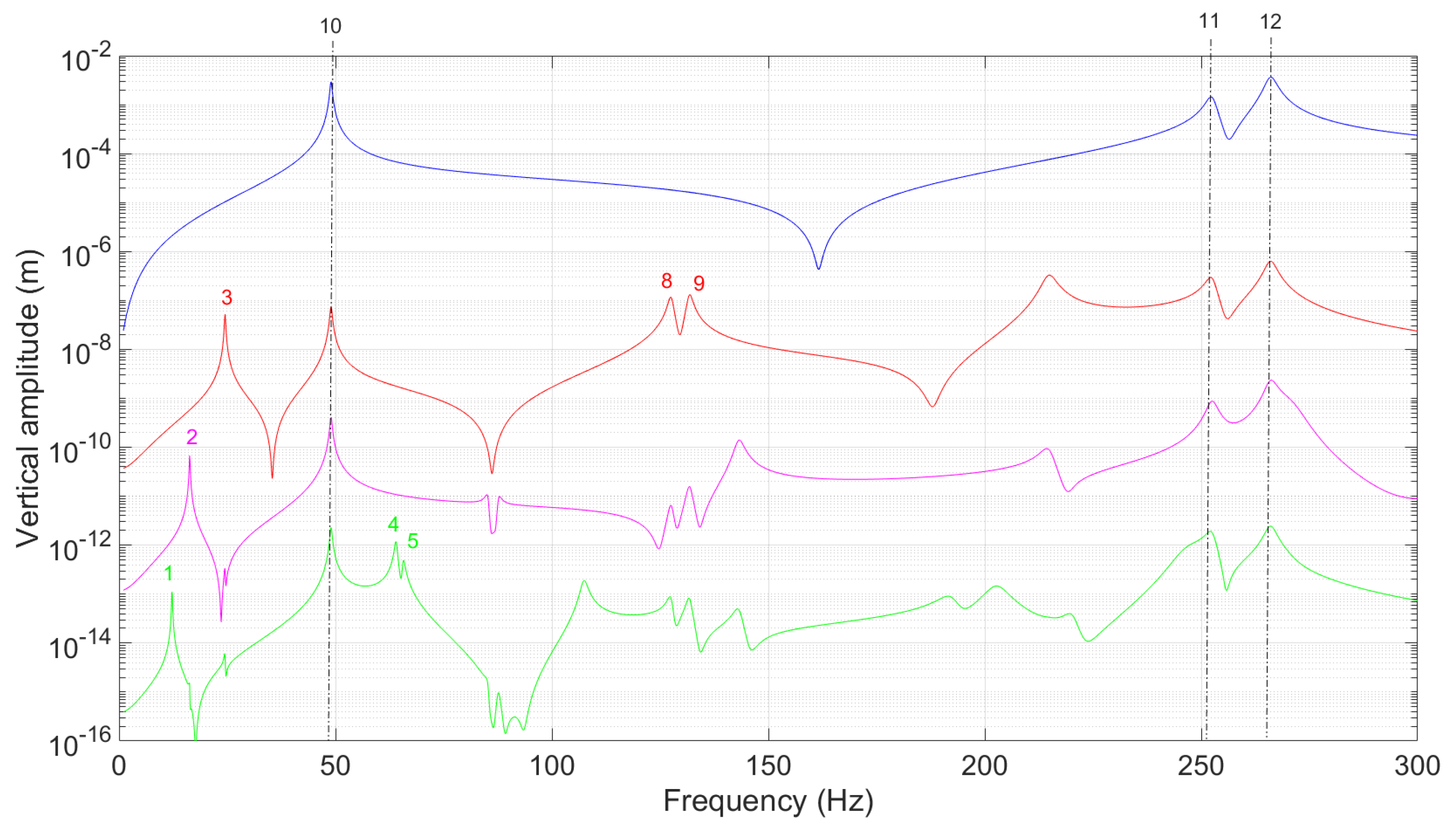
To briefly illustrate these well-known analyses of fault detection by examining the non-linear vibration signature, three case studies are proposed with the crack parameters specified in Table 2. These studies correspond to a case with a deep crack (i.e., case 1), and the other two cases consider a small crack located at different positions on the rotor shaft (i.e., cases 2 and 3). Figure 2, Figure 3 and Figure 4 show the non-linear response (i.e., the global response and the harmonic components 1 × , 2 × , 3 × , and 4 × ) for the cracked rotor in each case. It is clear that the presence of a breathing crack on the rotor results in the appearance of harmonics of the jth order with amplitude peaks when passing 1 j critical speeds (see more specifically the marks ( 1 , 4 , 5 ) , ( 2 , 6 , 7 ) , and ( 3 , 8 , 9 ) for 4 × , 3 × , and 2 × harmonic components, respectively). To better understand the proposed results and discussion, Table 3 gives the critical speeds of the cracked rotor system in the frequency range [ 0 ; 300 ] Hz. Moreover, the marks ( 10 , 11 , 12 ) also suggest the presence of resonance peaks for each j × harmonic component at the main critical speeds. By comparing the results obtained for the three case studies, it can also be concluded that:
  • If the size of the crack is large, the j × harmonic responses contribute significantly to the overall dynamic response of the rotor system, resulting in the presence of peaks when passing through 1 j critical speeds with amplitudes greater than the first-order response (see, for example, the marks ( 2 , 3 , 8 ) in Figure 2). However, in the practical context of a rotor system with a small crack, the presence of the crack is not apparent when inspecting the overall non-linear response alone, and it is necessary to specifically examine the responses of the j × harmonic contributions (see Figure 3 and Figure 4). Thus, the evolution of the j × harmonic components offers a positive and useful way to diagnose the presence and potential propagation of cracks in a practical way in both preventive and predictive maintenance.
  • Although—due to the presence of one crack—variations in the frequencies and critical speeds of a rotor system exist from a theoretical point of view, these changes are often too small to be considered as reliable indicators for the early detection of defects. This is highlighted in Table 3 and Table 4, which give the evolution of the critical speeds and the natural frequencies at rest in the case of a healthy rotor and the three cracked rotor configurations proposed in the present study. It should be noted that the calculations of the natural frequencies at rest are given for an open transverse crack, as illustrated in Figure 1. It has also been shown in previous studies [3,40,47] that the detection and identification of small defects in the presence of uncertainties (uncertainties in the vibration measurements or uncertainties in the physical model used) are often not possible if the analysis criteria are based exclusively on these evolutions of natural frequencies or critical speeds.
  • By comparing the vibration responses of several case studies for rotor systems with small cracks positioned at different locations (i.e., cases 2 and 3 for the present study), it appears that the evolutions of the first-order response (for a chosen vertical or horizontal location on the rotor) over the frequency range are very close. More precisely, the positions of the antiresonances are identical, and the evolution of the vibratory amplitudes between the resonance and antiresonance peaks are similar (see, for example, Figure 3 and Figure 4). It was also verified that this statement is valid for all vertical and horizontal amplitudes over the rotor system. Indeed, the only modification between these various cases comes from the position of the crack, which does not greatly modify the 1 × vibrational response of the rotor system because the latter is mainly governed by the imbalance in the case of a rotor system with a small crack. On the contrary, the evolutions of the higher-order responses and the value of the antiresonance frequencies are dependent on the position of the crack (see Figure 3 and Figure 4 for the 2 × , 3 × and 4 × harmonic responses). Consequently, a nondestructive detection technique based on the tracking of antiresonances should be a reliable and effective way for monitoring and identifying the locations of cracks in rotor systems when ensuring their structural health.

4.2. Crack Location Based on the Antiresonances of Higher Order Vibrational Responses

Based on the analysis carried out previously, the following section dealt with a robust approach to meet the challenges of predictive maintenance and thus promotes reliable monitoring of the condition of rotating systems by identifying the presence of a small crack. The main objective is to be able to identify one crack in the early state and consequently to prevent equipment failures that lead to costly downtime and repairs. The methodology proposed is based on using the antiresonances of higher-order responses for small crack detection and identifying the positions of cracks in rotor systems.
Firstly, a concise discussion on the linear equations of higher orders in the frequency domain is proposed. Through Equations (4), (6), and (9), it appears that the parametric terms due to the breathing behavior of the crack induce an additional internal force only at the crack location for all the harmonic components of the rotor response. As previously stated, the gravitational force is defined by Fourier series with only constant components, and the imbalance is exactly characterized by Fourier series with periodic components of the first order in the frequency domain. Therefore, it follows that the higher-order Fourier coefficients A k and B k (with k > 1 ) are directly excited only via the parametric terms contained in the matrix Λ c due to the presence of the breathing crack. More precisely, it follows that the linear equations of the unknown coefficients A k and B k (with k > 1 ) can be rewritten in the following form:
K k 2 ω 2 M 1 2 K c k ω D k ω D K k 2 ω 2 M 1 2 K c A k B k = K c 4 A k 1 + A k + 1 B k 1 + B k + 1
with
diag K c = δ i K c r a c k
where δ i = 1 for the dof of the ith element (i.e., at the location of the crack in the shaft rotor) and otherwise null. Thus, the right side of Equation (10) clearly indicates that the excitation contribution for the kth harmonic components is due only to the presence of the breathing crack, and so the excitation forces for the higher orders are located only at the crack location. It is also necessary to note that these excitations depend indirectly on the contributions of the gravitational and unbalance forces through the calculations of lower orders and the interconnections between orders via matrix Λ c (see Equations (6) and (9)). These observations lead us to assume that the antiresonance behavior of higher-order responses could be very effective for detecting and identifying cracks in rotor systems.
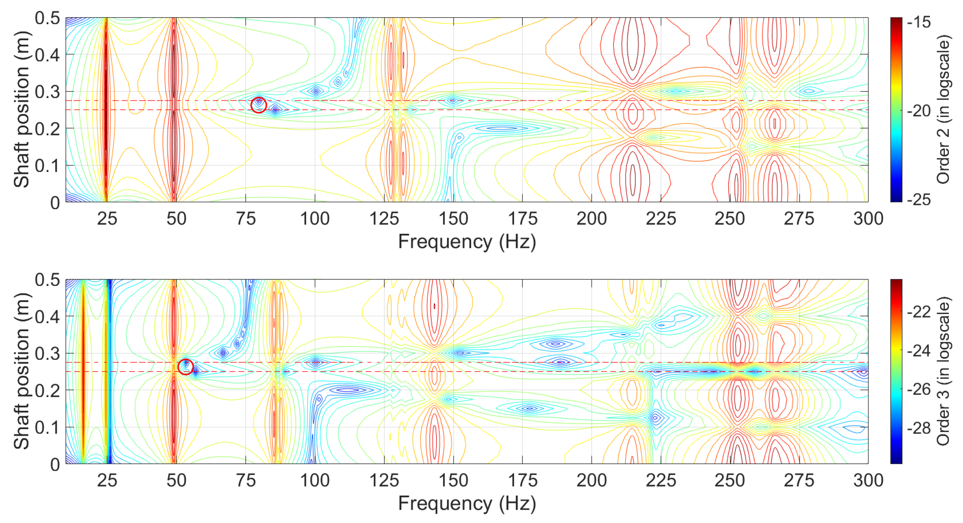
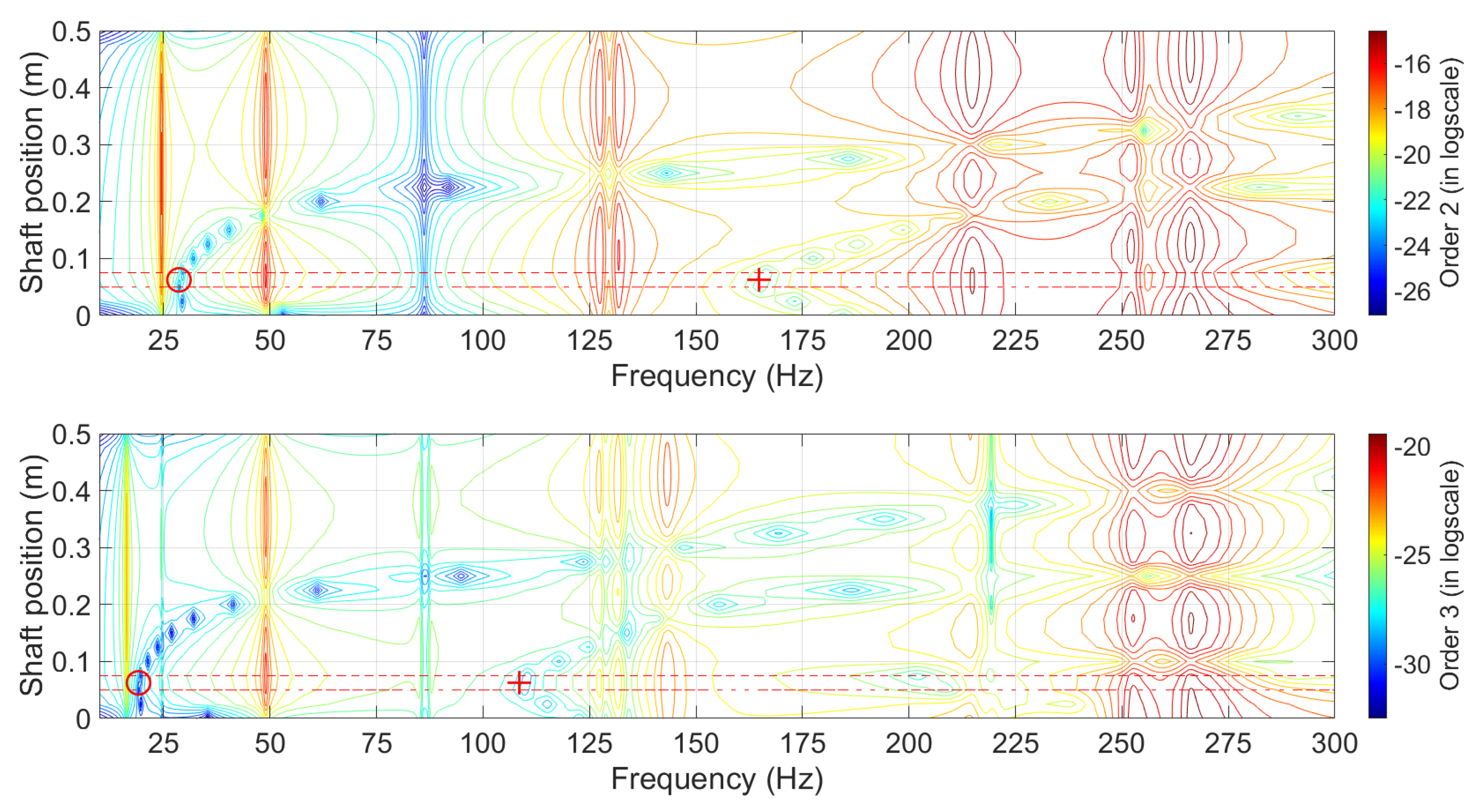
In the following, the numerical results associated with the three cases previously discussed in Section 4.1 are analyzed to consider the possibility of using the placement of antiresonance frequencies of higher orders to identify the crack location. Figure 5, Figure 6 and Figure 7 illustrate the vertical displacements for all the rotor shaft positions for the 2nd and 3rd orders by considering the three cases of cracked rotor discussed previously. The contour lines indicate the isolines of the vertical amplitudes for the 2nd and 3rd orders. To facilitate the reader’s comprehension, twenty contour lines are uniformly distributed between the minimum and maximum values of the amplitudes set in logarithmic scale. This has the advantage of providing a clear visualization of the evolution of the low-level amplitudes as a function of the position of the rotor shaft and the rotational speed, and thus highlights the evolution of the antiresonance frequencies of higher orders along the rotor.
Consequently, the high amplitude peaks that correspond to the fundamental critical speeds and 1 j n (with n = 0 , , j 1 , j > 1 ) of the critical speeds are indicated by the red contour lines, and the antiresonance frequencies are indicated by the blue contour lines. In addition, the two dotted red horizontal lines indicate the rotor element on which the crack is located. The red circle corresponds to the identification carried out for the crack location based on the minimum of the antiresonance frequencies (note that this criterion for detecting the damage location has already been mentioned for the locations of small cracks on beam systems [42,43] and will be explained in the following for application to rotor systems). In addition, the red cross corresponds to the identification of the crack location based on the minimum of the second antiresonance frequencies (if this identification is carried out successfully). In the following discussion, the notion of resonance frequency will generally be preferred to the exact notion of critical speed (i.e., undamped natural frequency of the rotor system due to imbalance), in order not to make the discussion too complex and to facilitate the understanding of the analysis of the results.
Based on the numerical results and additional studies which have been conducted by the author (but for which the results are not shown for the sake of conciseness), several conclusions can be proposed regarding the behavior of the antiresonances and their use for detecting and identifying a breathing crack in rotating machines:
  • The antiresonance frequencies of higher orders can be defined as local characteristics of the system that depend on both the driving point and the measurement point. This observation is of primary importance because the driving point is only non-null at the crack position for higher orders, since the excitation undergone by the rotor for the n × harmonic components (with n > 1 ) is due to the breathing behavior of the crack (for memory, see the expressions of Equations (10) and (11)).
  • On the contrary, not surprisingly, the resonance frequencies and super-harmonic resonances (i.e., the fundamental critical speeds and 1 j n of the critical speeds with n = 0 , , j 1 , and j > 1 ) are global quantities whose values do not depend on the measurement point.
  • The minimum value of the antiresonance frequencies of orders 2 and 3 is located at the crack location on the rotor system. It should be noted that this result is also valid for the nth orders with n > 3 , which are not shown in this study for the sake of conciseness.
  • Focusing on the vicinity of the antiresonance frequencies of orders 2 and 3, and increasing the distance between the crack location (i.e., excitation points for the 2nd and 3rd orders, and the shaft element with reduced stiffness) and the measurement point, will lead to higher antiresonance frequency values.
  • The resonance–antiresonance pattern is quite similar in both the vertical and horizontal directions. This can be explained by the fact that the only difference between the vertical and horizontal responses corresponds to the small dissymmetry in stiffness due to the breathing crack mechanism and the structural properties of the rotor supports of the rotor system under study. It should be noted that this commentary is based on the complete results of the different cases treated, which have been analyzed by the author but are not illustrated by figures in the study for the sake of brevity.
  • The resonance–antiresonance pattern is quite similar for cases where the crack size is different but the crack position is the same. It should be noted that this commentary is based on additional studies conducted by the author but not illustrated in this study. More precisely, the size of the crack only leads to a local stiffness reduction on the cracked element of the rotor system: increasing the crack size decreases the local stiffness, inducing a small decrease in the resonance and antiresonance frequencies of orders 2 and 3 and an overall increase in the amplitudes. In other words, there is a very slight shift on the left for the resonance–antiresonance patterns shown in Figure 6 and Figure 7, when the crack size increases. This result is very interesting because it allows us to conclude that the resonance–antiresonance pattern of higher orders is more sensitive to the crack position than the crack size.
  • Whatever the size of the crack, monitoring the antiresonance frequencies of higher orders appears to be a robust indicator of the damage location.
  • Contrary to the classical analysis on linear systems [44], the resonance–antiresonance behavior for the 2 × and 3 × harmonic responses where the excitation point and the measurement point coincide is not trivial. Indeed, there is no evidence of alternating resonances and antiresonances associated with the fundamental critical speeds or 1 j n (with n = 0 , , j 1 , j > 1 ) of the critical speeds.

5. Conclusions

The present work studied the primary characteristics of the nonlinear responses resulting from the introduction of a transverse breathing crack into a rotor system. Although the 2 × and 3 × harmonic components of the system’s response can serve as target observations for the monitoring system, this study also demonstrated that the antiresonance behavior of higher orders can be considered as one common and robust indicator to detect the presence of damage and the location of a small crack.
This paper highlighted that using and tracking the nonlinear signature has many advantages for structural health monitoring in rotordynamics and detecting and identifying damage at an early stage during operational conditions. In addition, this work points to several interesting perspectives for future research, as described in the following:
  • It was observed through this numerical study that the location of the crack corresponds to the minimum values of the antiresonance frequencies of the nth order (with n > 1 ). However, no formal proof was obtained on the subject in the present paper. To the author’s knowledge, there is no theoretical study in the field of rotordynamics on the sensitivity of antiresonance frequencies of the nth order to structural changes. Additionally, no theoretical study has yet demonstrated that damage location can be effectively found by tracking the antiresonances of the nth order. It would therefore be interesting to conduct theoretical work in this direction in order to generalize the idea. It can also be pointed out that there is very little research aimed at extending the general higher-order nonlinear analysis of FRF to the detection and damage assessment of general structural systems with breathing cracks [48,49]. Solid theoretical works on the influences of breathing cracks on the higher-order responses of nonlinear structural systems are of interest due to the strong potential for applications of HOFRF (higher-order vibrational responses) to damage identification and assessment in real structural systems (rotating machines).
  • It would be interesting to conduct experiments to validate the relevance of the approach proposed to detect crack locations by identifying the positioning of the antiresonance frequencies of higher orders. In a more practical context, where there are only a limited number of sensors and therefore only a limited number of measurement points on the rotor, the question arises as to how to optimally position these sensors to locate the damage. If increasing the distance between the location of the crack and the measurement point leads to an increase in the value of higher orders, then antiresonance frequencies seem to be factors favoring the possibility of robust defect detection in a practical case (by successive adaptation of the placement of the sensors for example). This deserves to be validated by extensive experimental studies.
  • Many faults that reduce the lifetime of rotating machinery exist, and they significantly affect the dynamics of rotor systems. It would be interesting to better understand the possibility of damage detection for rotor systems with features such as misalignment, bows, and asymmetric shafts. These faults can also generate nonlinear responses, so the resonance–antiresonance pattern of higher orders should therefore be used with caution to avoid irrelevant damage detection on complex industrial rotating machinery.
  • Even if multi-crack detection in the case of beam-like structures using the antiresonances locus of HOFRFs has been previously investigated by Chomette [43], this problem remains completely open and deserves further study for robust and reliable detection of multiple small cracks in rotating systems.

Funding

This research received no external funding.

Institutional Review Board Statement

Not applicable.

Informed Consent Statement

Not applicable.

Data Availability Statement

Not applicable.

Conflicts of Interest

The author declares no conflict of interest.

Abbreviations

The following abbreviations are used in this manuscript:
FRFFrequency Response Function
HOFRFHigh-Order Frequency Response Function
dofdegrees of freedom
HBMHarmonic Balance Method

References

  1. Salawu, O. Detection of structural damage through changes in frequency: A review. Eng. Struct. 1997, 19, 718–723. [Google Scholar] [CrossRef]
  2. Sekhar, A.S. Vibration characteristics of a cracked rotor with two open cracks. J. Sound Vib. 1999, 223, 497–512. [Google Scholar] [CrossRef]
  3. Sinou, J.-J. A robust identification of single crack location and size only based on pulsations of the cracked system. Struct. Eng. Mech. 2007, 25, 691–716. [Google Scholar] [CrossRef] [Green Version]
  4. Bamnios, Y.; Douka, E.; Trochidisi, A. Crack identification in beam structures using mechanical impedance. J. Sound Vib. 2002, 256, 287–297. [Google Scholar] [CrossRef]
  5. Dilena, M.; Morassi, A. The use of antiresonances for crack detection in beams. J. Sound Vib. 2004, 276, 195–214. [Google Scholar] [CrossRef]
  6. Dharmaraju, N.; Sinha, J.K. Some comments on use of antiresonance for crack identification in beams. J. Sound Vib. 2005, 286, 669–671. [Google Scholar] [CrossRef]
  7. Dansheng, W.; Hongping, Z.; Chuanyao, C.; Yong, X. An impedance analysis for crack detection in the Timoshenko beam based on the antiresonance technique. Acta Mech. Solida Sin. 2007, 20, 228–235. [Google Scholar]
  8. Papadopoulos, C.; Dimarogonas, A. Coupled longitudinal and bending vibrations f a rotating shaft with an open crack. J. Sound Vib. 1987, 117, 81–93. [Google Scholar] [CrossRef]
  9. Collins, K.; Plaut, R.; Wauer, J. Detection of cracks in rotating Timoshenko shafts using axial impulses. J. Vib. Acoust. 1991, 113, 74–78. [Google Scholar] [CrossRef]
  10. Liu, D.; Gurgenci, H.; Veidt, M. Crack detection in hollow section structures through coupled response measurements. J. Sound Vib. 2003, 261, 17–29. [Google Scholar] [CrossRef]
  11. Ostachowicz, W.; Krawczuk, M. Coupled torsional and bending vibrations of a rotor with an open crack. Arch. Appl. Mech. 1992, 62, 191–201. [Google Scholar] [CrossRef]
  12. Gudmundson, P. The dynamic behaviour of slender structures with cross sectional cracks. J. Mech. Phys. Solids 1983, 31, 329–345. [Google Scholar] [CrossRef]
  13. Davies, W.G.R.; Mayes, I.W. The vibrational behaviour of a multi-shaft multi-bearing system in the presence of a propagating transverse crack. Trans. ASME J. Vib. Acoust. Stress. Reliab. Des. 1984, 106, 146–153. [Google Scholar] [CrossRef]
  14. Davies, W.G.R.; Mayes, I.W. Analysis of the response of a multi-rotor-bearing system containing a transverse crack in a rotor. Trans. ASME J. Vib. Acoust. Stress. Reliab. Des. 1984, 106, 139–145. [Google Scholar]
  15. Pugno, N.; Surace, C.; Ruotolo, R. Evaluation of the non-linear dynamic response to harmonic excitation of a beam with several breathing cracks. J. Sound Vib. 2000, 235, 749–762. [Google Scholar] [CrossRef] [Green Version]
  16. Sinou, J.-J.; Lees, A. Influence of cracks in rotating shafts. J. Sound Vib. 2005, 285, 139–145. [Google Scholar] [CrossRef] [Green Version]
  17. Al-Shudeifat, M.-A.; Butcher, E.-A. New breathing functions for the transverse breathing crack of the cracked rotor system: Approach for critical and subcritical harmonic analysis. J. Sound Vib. 2011, 330, 526–544. [Google Scholar] [CrossRef]
  18. Gasch, R. A survey of the dynamic behaviour of a simple rotating shaft with a transverse crack. J. Sound Vib. 1993, 160, 313–332. [Google Scholar] [CrossRef]
  19. Sekhar, A.; Prabhu, B. Condition monitoring of cracked rotors through transient response. Mech. Mach. Theory 1998, 33, 1167–1175. [Google Scholar] [CrossRef]
  20. Sekhar, A. Crack detection through wavelet transform for a run-up rotor. J. Sound Vib. 2003, 259, 461–472. [Google Scholar] [CrossRef]
  21. Darpe, A.; Gupta, K.; Chawla, A. Transient response and breathing behaviour of a cracked jeffcott rotor. J. Sound Vib. 2004, 272, 207–243. [Google Scholar] [CrossRef]
  22. Sinou, J.-J.; Lees, A. A non-linear study of a cracked rotor. J. Eur. Mech. A/Solids 2007, 26, 152–170. [Google Scholar] [CrossRef]
  23. Sinou, J.-J. Detection of cracks in rotor based on the 2× and 3× super-harmonic frequency components and the crack–unbalance interactions. Commun. Nonlinear Sci. Numer. Simul. 2008, 13, 2024–2040. [Google Scholar] [CrossRef] [Green Version]
  24. Sinou, J.-J. An experimental investigation of condition monitoring for notched rotors through transient signals and wavelet transform. Exp. Mech. 2008, 49, 683–695. [Google Scholar] [CrossRef]
  25. Sinou, J.-J. Experimental response and vibrational characteristics of a slotted rotor. Commun. Nonlinear Sci. Numer. Simul. 2009, 14, 3179–3194. [Google Scholar] [CrossRef] [Green Version]
  26. Kushwaha, N.; Patel, V.N. Nonlinear dynamic analysis of two-disk rotor system containing an unbalance influenced transverse crack. Nonlinear Dyn. 2022, 1–29. [Google Scholar] [CrossRef]
  27. Wauer, J. Dynamics of cracked rotors: Literature survey. Appl. Mech. Rev. 1990, 43, 13–17. [Google Scholar] [CrossRef]
  28. Dimarogonas, A. Vibration of cracked structures: A state of the art review. Eng. Fract. Mech. 1996, 55, 831–857. [Google Scholar] [CrossRef]
  29. Doebling, S.; Farrar, C.; Prime, M. A summary review of vibration-based damage methods. Shock Vib. Dig. 1998, 30, 91–105. [Google Scholar] [CrossRef] [Green Version]
  30. Sinou, J.-J. A review of damage detection and health monitoring of mechanical systems from changes in the measurement of linear and non-linear vibrations. In Mechanical Vibrations: Measurement, Effects and Control; Sapri, R.R., Ed.; Nova Science Publishers: Hauppauge, NY, USA, 2009; pp. 643–702. ISBN 978-1-60692-037-4. [Google Scholar]
  31. Kumar, C.; Rastogi, V. A brief review on dynamics of a cracked rotor. Int. J. Rotating Mach. 2009, 2009, 758108. [Google Scholar] [CrossRef]
  32. Bachschmid, N.; Pennacchi, P.; Tanzi, E. Cracked Rotors: A Survey on Static and Dynamic Behaviour Including Modelling and Diagnosis; Springer Science and Business Media: Berlin, Germany, 2010; pp. 129–148. [Google Scholar]
  33. Fan, W.; Qiao, P. Vibration-based damage identification methods: A review and comparative study. Struct. Health Monit. 2011, 10, 83–111. [Google Scholar] [CrossRef]
  34. Bovsunovsky, A.; Surace, C. Non-linearities in the vibrations of elastic structures with a closing crack: A state of the art review. Mech. Signal Process. 2015, 62–63, 129–148. [Google Scholar] [CrossRef]
  35. Sinou, J.-J.; Faverjon, B. The vibration signature of chordal cracks in a rotor system including uncertainties. J. Sound Vib. 2012, 331, 138–154. [Google Scholar] [CrossRef] [Green Version]
  36. Fu, C.; Ren, X.; Yang, Y.; Lu, K.; Wang, Y. Nonlinear response analysis of a rotor system with a transverse breathing crack under interval uncertainties. Int. J. Non-Linear Mech. 2018, 105, 77–87. [Google Scholar] [CrossRef]
  37. Fu, C.; Ren, X.; Yang, Y.; Lu, K.; Qin, W. Steady-state response analysis of cracked rotors with uncertain-but-bounded parameters using a polynomial surrogate method. Commun. Nonlinear Sci. Numer. Simul. 2019, 68, 240–256. [Google Scholar] [CrossRef]
  38. Yongfeng, Y.; Qinyu, W.; Yanlin, W.; Weiyang, Q.; Kuan, L. Dynamic characteristics of cracked uncertain hollow-shaft. Mech. Syst. Signal Process. 2019, 124, 36–48. [Google Scholar] [CrossRef]
  39. Fu, C.; Xu, Y.; Yang, Y.; Lu, K.; Gu, F.; Ball, A. Dynamics analysis of a hollow-shaft rotor system with an open crack under model uncertainties. Commun. Nonlinear Sci. Numer. Simul. 2020, 83, 105102. [Google Scholar] [CrossRef]
  40. Sinou, J.-J. Denimal, E. Reliable crack detection in a rotor system with uncertainties via advanced simulation models based on kriging and Polynomial Chaos Expansion. Eur. J. Mech. Solids 2022, 92, 104451. [Google Scholar] [CrossRef]
  41. Fu, C.; Sinou, J.-J.; Zhu, W.; Lu, K.; Yang, Y. A state-of-the-art review on uncertainty analysis of rotor system. Mech. Syst. Signal Process. 2023, 183, 109619. [Google Scholar] [CrossRef]
  42. Sinou, J.-J. On the use of non-linear vibrations and the antiresonances of Higher-Order Frequency Response Functions for crack detection in pipeline beam. Mech. Res. Commun. 2012, 43, 87–95. [Google Scholar] [CrossRef] [Green Version]
  43. Chomette, B. Nonlinear multiple breathing cracks detection using direct zeros estimation of higher-order frequency response function. Commun. Nonlinear Sci. Numer. Simul. 2020, 89, 105330. [Google Scholar] [CrossRef]
  44. Wahl, F.; Schmidt, G.; Forrai, L. On the significance of antiresonance frequencies in experimental structural analysis. J. Sound Vib. 1999, 219, 379–394. [Google Scholar] [CrossRef]
  45. D’Ambrogio, W.; Fregolent, A. The use of antiresonances for robust model updating. J. Sound Vib. 2000, 236, 227–243. [Google Scholar] [CrossRef]
  46. Hanson, D.; Waters, T.P.; Thompson, D.J.; Randall, R.B.; Ford, R.A.J. The role of antiresonance frequencies from operational modalanalysis in finite element model updating. J. Sound Vib. 2007, 21, 74–97. [Google Scholar]
  47. Sinou, J.-J. Damage assessment based on the Frequencies’ Ratio Surfaces Intersection method for the identification of the crack depth. Struct. Durab. Health Monit. 2007, 3, 133–164. [Google Scholar]
  48. Lin, R.M.; Ng, T.Y. Applications of higher-order frequency response functions to the detection and damage assessment of general structural systems with breathing cracks. Int. J. Mech. Sci. 2018, 148, 652–666. [Google Scholar] [CrossRef]
  49. Lin, R.M.; Ng, T.Y. Higher-order FRFs and their applications to the identifications of continuous structural systems with discrete localized nonlinearities. Mech. Syst. Signal Process. 2018, 108, 326–346. [Google Scholar] [CrossRef]
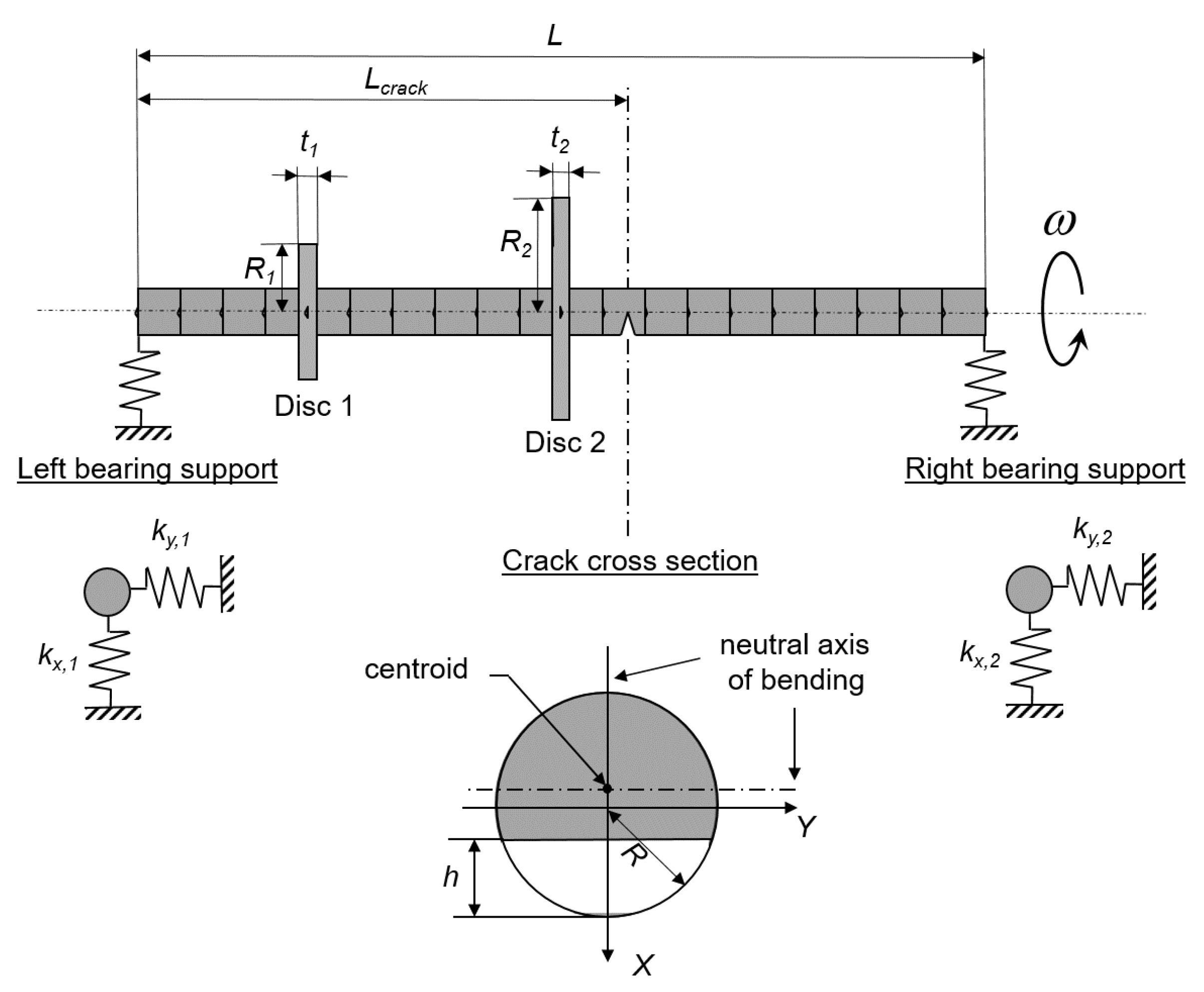
Figure 1. Model of a rotor system with one crack.
Applsci 12 11904 g001
Figure 2. Vertical amplitudes at 0.1 m from the left side of the rotor system with a breathing crack (case 1— μ = 1 and L c r a c k = 0.3625 m from the left side) (blue = nonlinear response, black = order 1, red = order 2, magenta = order 3, green = order 4).
Applsci 12 11904 g002
Figure 3. Vertical amplitudes at 0.1 m from the left side of the rotor system with a breathing crack (case 2— μ = 0.1 and L c r a c k = 0.2625 m from the left side) (blue = nonlinear response, black = order 1, red = order 2, magenta = order 3, green = order 4).
Applsci 12 11904 g003
Figure 4. Vertical amplitudes at 0.1 m from the left side of the rotor system with a breathing crack (case 3— μ = 0.1 and L c r a c k = 0.0625 m from the left side) (blue = nonlinear response, black = order 1, red = order 2, magenta = order 3, green = order 4).
Applsci 12 11904 g004
Figure 5. Case 1—Identification of the crack location based on the antiresonances of orders 2 and 3 (results are drawn for the vertical amplitudes in the log-scale).
Applsci 12 11904 g005
Figure 6. Case 2—Identification of the crack location based on the antiresonances of orders 2 and 3 (results are drawn for the vertical amplitudes in log-scale).
Applsci 12 11904 g006
Figure 7. Case 3—Identification of the crack location based on the antiresonances of orders 2 and 3 (results are drawn for the vertical amplitudes in log-scale).
Applsci 12 11904 g007
Table 1. Mechanical and geometrical properties of the rotor system.
DescriptionNotationValue
Radius of the shaftR0.005 m
Length of the shaftL0.5 m
Outer radius of discs 1 and 2 R 1 and R 2 0.025 m and 0.01 m
Thickness of discs 1 and 2 t 1 and t 2 0.015 m
Mass unbalance m u 0.001 kg
Eccentricity of the mass unbalance e u 0.01 m
Left vertical support stiffness k x , 1 5 × 10 5 N/m
Left horizontal support stiffness k y , 1 7.5 × 10 5 N/m
Right vertical support stiffness k x , 2 5 × 10 5 N/m
Right horizontal support stiffness k y , 2 5 × 10 5 N/m
Density of the shaft rotor ρ 7800 kg/m 3
Young’s modulus of elasticity for the shaft rotorE2 × 10 11 N/m 2
Poisson ratio ν 0.3
Density of discs 1 and 2 ρ 1 and ρ 2 7800 kg/m 3
First Rayleigh damping coefficient α 2.6
Second Rayleigh damping coefficient β 5 × 10 6
Table 2. Sets of parameters for the crack element.
CaseCrack Depth μ Crack Location L crack
110.3625 m
20.10.2625 m
30.10.0625 m
Table 3. Critical speeds of the healthy or cracked rotor system.
f 1 (Hz) f 2 (Hz) f 3 (Hz) f 4 (Hz)
Healthy rotor49.049.2252.3266.1
Case 148.449.1249.4264.6
Case 249.049.2252.3266.1
Case 349.049.2252.2266.1
Table 4. Natural frequencies of the healthy or cracked rotor system at rest.
f 1 (Hz) f 2 (Hz) f 3 (Hz) f 4 (Hz)
Healthy rotor49.049.2256.3262.3
Case 147.749.0248.0260.8
Case 248.949.1256.3262.3
Case 349.049.2256.2262.2
Publisher’s Note: MDPI stays neutral with regard to jurisdictional claims in published maps and institutional affiliations.