Abstract
To get a better electromagnetic performance of an axial flux permanent magnet brushless DC motor (AFPMBLDC), an AFPMBLDC with arc-shaped magnets and its multi-objective optimization design are researched. Firstly, the main design parameters of the AFPMBLDC are proposed, and the initial designs are carried out according to the given requirements. Furthermore, the pole arc coefficient, permanent magnet thickness, permanent magnet arc radius, and air-gap length are selected as optimization factors. Then, an orthogonal experiment table is established, in which the flux density, no-load back EMF, harmonic distortion rate, and output torque ripple are selected as optimization targets. The Taguchi optimization method is adopted to optimize the performance indexes and the optimal parameters are obtained. Finally, the optimized model is constructed, and some simulations are carried out to verify the optimal design. The research results have shown that the air-gap flux density of the optimized AFPMBLDC is reduced to 31.8%, the total harmonic distortion rate of no-load back EMF is less than 7.5%, and the torque ripple is reduced to 4.3%.
1. Introduction
An axial flux permanent magnet brushless DC motor (AFPMBLDC) has the advantages of a short axial length, small size, light weight, and high power density [1,2]. In the past two decades, the AFPMBLDCs have been widely researched throughout the world. In [3,4], we found that the AFPMBLDC can provide a larger output torque compared with the radial flux brushless DC motor. However, the torque ripple cannot be neglected due to the high cogging torque. Thus, some design methods, such as fractional slot winding, stator skewed slot, and best pole slot fit method, are adopted to optimize the output torque [5,6]. However, the above methods are only aimed at a single design method, which only improves the output torque of AFPMBLDC, leaving the problems of low efficiency and large losses [7,8].
In order to improve the comprehensive performance of permanent magnet motors, a variety of optimization design methods have been proposed [9,10]. Generally, optimization design methods are divided into global optimization and local optimization [11,12]. Global optimization algorithms include the particle swarm optimization algorithm, genetic algorithm, ant colony algorithm, and simulated annealing algorithm, etc. The literatures [13,14,15,16,17,18] used particle swarm optimization algorithm to optimize the parameters so that the permanent magnet motor has the characteristics of small coupling and simple control. Li Zhe et al. used the particle swarm reduction algorithm to optimize the parameters, which greatly reduced the torque ripple and made the motor run more smoothly [19]. The authors of [20] optimized the surface-mounted permanent magnet synchronous motor using a genetic algorithm improved by combining pattern search method. Ying Xie and Qin fen Lu improved the accuracy and speed of the genetic ant colony algorithm [21]. Guo Liang and Li Ji xing et al. used the particle swarm optimization algorithm to improve the materials utilization of a permanent magnet motor [22]. In [23,24], a hybrid genetic simulated annealing algorithm and conformal mapping approach were applied for multi-objective analysis to optimize the motor, respectively. In [25], the authors performed a multi-objective optimization of a permanent magnet motor based on a forbidden search algorithm and a finite element method. In [26], the efficiency, size, and quality of a PMG were optimally designed using a non-dominated ranking genetic algorithm technique, which allows an arbitrary selection of the number of optimization objectives. The establishment of the objective function of these global optimization algorithms is complex and the solution cycle is generally long, which makes it difficult to achieve a fast and efficient search for the optimal combination of the parameters of the motor.
The local optimization methods include the magnetic network method, gradient descent method, and finite element method [27]. Wang Xiao yuan et al. used the finite element method to make an analysis of the temperature field of the coreless disk motor to optimize the motor winding [28,29,30]. Yu Shen bo et al. used the equivalent magnetic network method to establish the equivalent network model considering the magnetic leakage coefficient and air-gap magnetic density to solve the time-consuming problem of AFPMBLDC [31]. Sheng Yi fa and Tang Zhao hui et al. used the gradient descent method to correct the motor setting value for the weak magnetic control [32,33]. Although the above local optimization methods are simple to calculate and have good convergence, they can only optimize for a single objective and cannot achieve multi-objective optimizations. Compared with local optimization methods, the Taguchi optimization method has the merits of achieving multiple objectives simultaneously and finding the optimal combinations of multi-objective optimization by fewer experiments [34,35,36]. Lu Yang et al. applied Taguchi method to optimize a new type of permanent magnet synchronous motor with parameters, such as the tooth slot torque and torque ripple coefficient [37,38]. Wen Jia bin et al. also the applied Taguchi method to optimize a permanent magnet synchronous motor with parameters such as efficiency and cogging torque [39].
In summary, an intelligent algorithm can improve the optimized results of AFPMBLDC with arc-shaped magnets to some extent. Therefore, in this paper, the pole arc coefficient, permanent magnet thickness, permanent magnet arc radius, and air-gap length of the AFPMBLDC are reasonably selected as optimization variables based on the Taguchi method. Furthermore, the flux density, no-load back EMF, and output torque are used as optimization targets. Then, an orthogonal experiment matrix is established to obtain the influence weight of each optimization variable on each optimization target. Finally, the optimal combination of the variables is obtained according to the optimization target. The analysis model is constructed, and the performances are simulated and analyzed using the finite element method. The effectiveness of the optimization design method is proved by comparing the results with the performances of the initial AFPMBLDC.
2. Structure and Main Parameters
2.1. Structure
Figure 1 shows the three-dimensional exploded view of the AFPMBLDC. It is characterized by the use of arc-shaped magnets to ameliorate the air-gap magnetic field waveform. The magnet section is shown in Figure 2, which is surrounded by the lower-end face, the upper-end face, the left edge, and the right edge. The left and right edges are vertical to the lower-end face. The lower-end face is connected to the rotor core, and the upper-end face is arc-shaped. F0 is the midpoint of the arc of the upper end face. The initial arc radius of the upper-end face is Rinitial, and the optimized arc radius is Roptimization. The arc radius optimization design method, Roptimization, will be discussed in detail later.
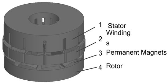
Figure 1.
Structure of the Proposed AFPMBLDC.
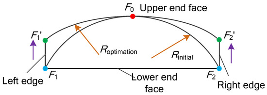
Figure 2.
Permanent magnet section.
2.2. Main Parameters
2.2.1. No-Load Back EMF
Assume that the inner diameter of the magnet is Di and the outer diameter is Do. In this article, the inner and outer diameters of the permanent magnet are consistent with the inner and outer diameters of the motor. The magnet section is shown in Figure 3. Between the inner radius Ri and the outer radius RO of the magnet, by taking any length, and when dC is rotated at an angular velocity Ω with angle dθ, then the average induced electromotive force generated by a single effective conductor at a certain pole angle is
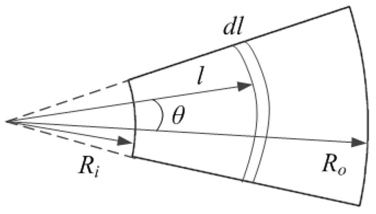
Figure 3.
Magnet section.
If the number of coil turns per phase is Nx, the winding coefficient is Kx, and the number of parallel branches of the winding is a, then the peak induced electric potential per phase winding Ema can be calculated by
where Bδav is the average air-gap magnetic density of the motor at one pole pitch, ; αi is the pole arc coefficient.
2.2.2. Electromagnetic Power
The electrical load at the minimum diameter Amax is as follows:
where Kt is the armature winding energization coefficient; Aav is average electrical load:
The phase current Ima of a AFPMBLDC can be expressed as
Assuming that the motor is in the m-phase and the rated speed of the motor is n, the output electromagnetic power of the AFPMBLDC can be obtained as follows:
where β is the ratio of the motor’s outer diameter to inner diameter, and the value is ; thus, the outer diameter Do of AFPMBLDC can be written by
2.2.3. Electromagnetic Torque
The electromagnetic torque of the motor can be expressed as
The AFPMBLDC parameter preliminary design is completed. The rated speed, rated power, rated voltage, and rated current are 4800 r/min, 300 W, 24 V, and 10 A, respectively. The pole arc coefficient, permanent magnet thickness, permanent magnet arc radius, and air-gap length are preliminarily set as 0.6, 3.0 mm, 1.8 mm, and 0.6 mm. The specific data are shown in Table 1.

Table 1.
Main parameters of AFPMBLDC.
3. Multi-Objective Optimization
3.1. Taguchi’s Method
Taguchi algorithm is a local optimization algorithm. It can quickly explore the optimal combination of parameters for multi-objective optimization using the minimum number of experiments and the minimum experimental data, and has the advantages of high efficiency, fast convergence, global selection, and robustness [40]. It has been studied and applied in the field of motor optimization in recent years.
The step flow of Taguchi method is shown in the Figure 4.
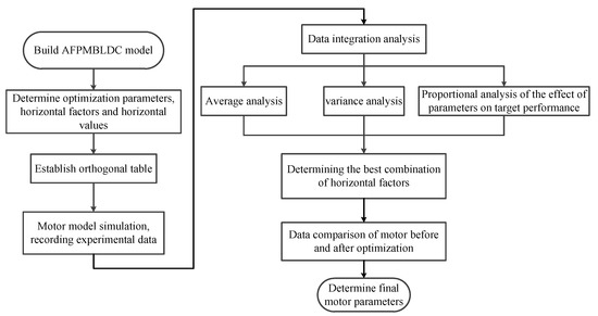
Figure 4.
Flow chart of the Taguchi method.
3.2. Multi-Objective Optimization Design
3.2.1. Orthogonal Experimental Design
The multi-objective optimization was carried out for the AFPMBLDC with arc-shaped magnets and the following three objectives were selected as indicators: flux density, no-load back EMF, and output torque. The optimized flux density is expected to be stronger and the total harmonic distortion rate of no-load back EMF is expected to be smaller. The optimized parameters are selected as “A”, representing the pole arc coefficient; “B” representing permanent magnet thickness; “C” representing permanent magnet arc radius; and “D” representing air-gap length.
The level value of the optimized parameters is selected according to the experience parameters of the motor design and the actual processing technology. The parameter ranges of the pole arc coefficient, magnet thickness, magnet arc radius, and air-gap length are shown in Table 2, and the four values of horizontal values are shown in Table 3.

Table 2.
Parameters of the model.

Table 3.
Parameters of the model.
Based on the four variable optimization parameters selected above, a range of four level factors were determined for each parameter, an orthogonal table was established. If the traditional single-variable optimization method was used; 44 = 256 experiments are required, while only 4 × 4 = 16 experiments are required to achieve the multivariable and multi-objective optimization design of the motor using Taguchi’s method. The orthogonal table for establishing experiment L16(4 × 4) is shown in Table 4. Among them, 1, 2, 3 and 4 respectively correspond to horizontal influence factor 1, horizontal influence factor 2, horizontal influence factor 3 and horizontal influence factor 4 in Table 3.

Table 4.
Orthogonal table.
Using the time-step finite element method, the three-dimensional simulation model of the AFPMBLDC with arc-shaped magnets is constructed, and the three optimization objectives of each group of experiments are analyzed and calculated by using the transient field solver after the winding is intense and the mesh is dissected. The Mag-B represents the flux density, “E” represents the no-load back EMF, and “T” represents the output torque.
Based on the data in the orthogonal table, the motor model is simulated. The specific values of flux density, no-load back EMF, and output torque are shown in Table 5. For example, the data result of No. 1 in Table 5 is the result of motor parameter simulation based on the data of No. 1 in Table 4; that is, under the condition of a motor pole arc coefficient of 0.6: a permanent magnet thickness of 2.0 mm, a permanent magnet arc radius of 18 mm, and air-gap length of 0.5 mm, the flux density is 0.59 T; the no-load back EMF is 8.56 V, and output torque is 0.52 V.

Table 5.
Orthogonal experimental results.
3.2.2. Mean Value and Weight Ratio Analysis
The mean values of the experimental results were statistically analyzed the effects of parameter changes on each performance index. The formula for calculating the mean value of all the finite element results for each performance index is shown in Equation (9), and the results are shown in Table 6.
where n is the number of experiments, Sa is the value of a certain target performance index for the a-th experiment.

Table 6.
Results on the overall average.
The average value of each motor optimization parameter corresponding to a particular optimization target at each level value is calculated as
where x represents the motor optimization parameter, hxa denotes the average value of the target performance index under the a-th influence factor of parameter x, hx denotes the target performance index under a certain experiment of parameter x, and g, p, k, and z denote the experiment serial numbers.
According to the formula, the average values of motor flux density, no-load back EMF, and output torque for each optimization variable taken at different levels are shown in Table 7, Table 8 and Table 9.

Table 7.
Mean value of magnetic flux density for each variable at the horizontal factor.

Table 8.
Average no-load back EMF for each variable at the horizontal factor.

Table 9.
Mean value of torque for each variable at the level factor.
The variance is used to assess the extent to which a number deviates from the mean. By analyzing the variance, the proportion of the effect of the parameter on the performance index can be calculated, and the formula for calculating the variance is (11).
The weight of the influence is shown in Table 10. It can be concluded that the pole arc coefficient has the widest influence on the optimization target, and has a great influence on the flux density, no load back EMF and output torque of the motor. The influence of the permanent magnet thickness on the no load back EMF and output torque is basically the same. The influence of the permanent magnet arc radius on the output torque is large, and the influence of the air-gap length on the output torque is large.

Table 10.
Proportion of influence of the parameters on target performance.
3.2.3. Analysis of Optimization Results
The mean main effects plot of Taguchi’s method is the average response for each combination of control factor levels. The optimization objective is to determine the level of factors that minimizes or maximizes the mean value, depending on the response. The experimental results of Taguchi’s algorithm in the previous section were statistically analyzed, and the mean main effect plots for each variable at varying levels are shown in Figure 5, with the vertical coordinates corresponding to the level values of the factors.
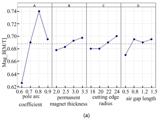
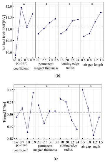
Figure 5.
Influence of the parameter influence factors on target performance. (a) The effect of the parameter level factor on air-gap magnetic density. (b) The effect of the parameter level factor on no-load back EMF. (c) Effect of the parameter level factor on the output torque.
From Figure 5a, it can be concluded that when the air-gap flux density is selected as small, the parameter combination is A1, B1, C1, and D1; that is, the pole arc coefficient, permanent magnet thickness, cutting edge radius, and air-gap length are 0.6, 2.0 mm, 18 mm and 0.5 mm, respectively; From Figure 5b, when the no-load back EMF is selected as large, the parameter combination is A2, B4, C4, and D4; that is, the pole arc coefficient, permanent magnet thickness, cutting edge radius, and air-gap length are 0.7, 3.5 mm, 24 mm, and 1.5 mm, respectively. It can be concluded from Figure 5c that when the output torque is selected as small, the parameter combination is A3, B2, C4, and D3; that is, the pole arc coefficient, permanent magnet thickness, permanent magnet arc radius, and air-gap length are 0.8, 2.5 mm, 24 mm, and 1.2 mm, respectively.
There are contradictions in the selection of the various parameters, and different parameters have different effects on the optimization objectives. The output torque and air-gap magnetic density are not the smaller the better. The no-load back EMF can meet the design requirements. Therefore, according to the proportion analysis of the influence of the four parameters on the performance of the optimization target, the final motor optimization parameters are A2, B2, C4, and D2; that is, the pole arc coefficient, thickness of the permanent magnet, permanent magnet arc radius, and air-gap length are 0.7, 2.5 mm, 24 mm, and 0.8 mm, respectively.
4. Optimization Results
The transient time-stepping finite element method was used to calculate the optimized electromagnetic performances. Simulation analysis was done for the combined parameters to compare the motor flux density, no-load back EMF, and output torque before and after optimization.
Figure 6 gives the air-gap flux density of the AFPMBLDC. It can be seen that the air-gap flux density of the motor before optimization is 1.1 T, and the air-gap magnetic density is too large, which means that the air-gap of the motor is too small and the assembly requirements of the motor are high. After optimization, the air-gap flux density of the motor is 0.75 T, which is 31.8% lower, and the air-gap flux density waveform is closer to sinusoidal, which is conducive to reducing the torque ripple and loss and increasing the output torque.
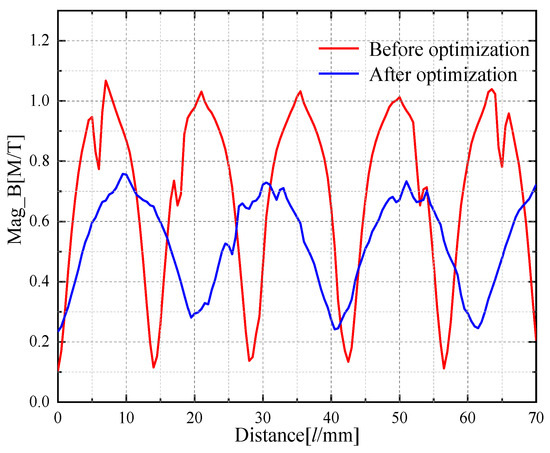
Figure 6.
Air-gap flux density.
Figure 7 shows the comparison of the no-load back EMF before and after optimization of the AFPMBLDC. The total harmonic distortion rate of the optimized no-load back EMF waveform is reduced by 7.5% when AFPMBLDC are running at the rated speed. Compared with the no-load back EMF before optimization, the optimized no-load back EMF has an RMS value of 8.8 V, which is 8.6% higher.
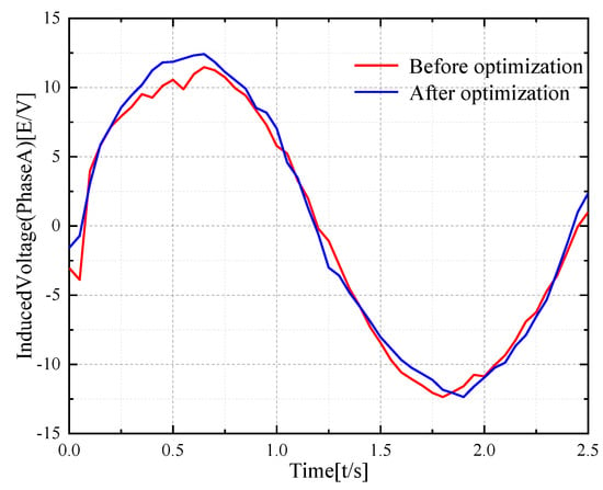
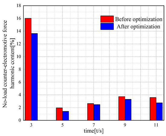
Figure 7.
Back EMF.
The output torque graph of the AFPMBLDC is shown in Figure 8. The motor’s average output torque before optimization was 0.504 Nm, while after optimization, the average output torque was 0.491 Nm, a 2.5 percent reduction. The motor torque ripple after optimization is 4.3 percent lower than before optimization, with a smoother waveform and improved motor stability.
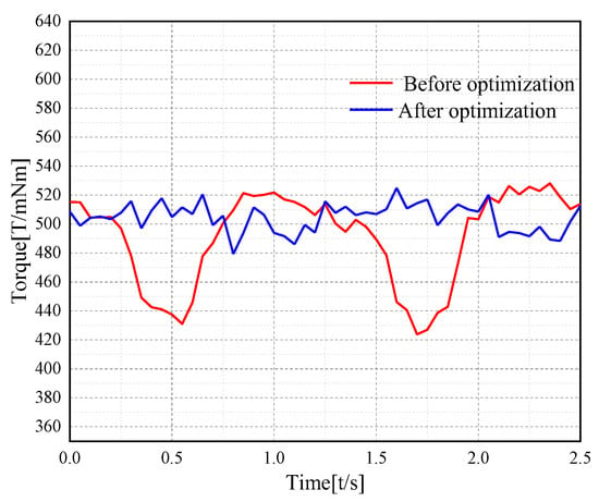
Figure 8.
Output torque.
5. Conclusions
The Taguchi optimization method uses four parameters, namely, pole arc coefficient, permanent magnet thickness, permanent magnet arc radius, and air-gap length, as the optimization variables to optimize the flux density, no-load back EMF, and output torque of the AFPMBLDC, with unequal thickness poles as the target. The Maxwell 3D finite element method is used to compare the 3D transient electromagnetic field simulation analysis of the generator before and after optimization, and the following conclusions are drawn:
- Using Taguchi’s optimization method to find the optimal four parameters, the optimized motor air-gap flux density was reduced by 31.8%, the total harmonic distortion rate was reduced by 7.5%, and the torque ripple was reduced by 4.3%.
- The feasibility of the proposed method for the optimization of the axial flux PMG is verified by Maxwell 3D finite element simulation.
In summary, Taguchi’s optimization method can be effectively applied to the parameter optimization of an AFPMBLDC with unequal thickness poles, and it can improve its performance. This scheme provides some reference for the optimization design of an AFPMBLDC.
Author Contributions
Conceptualization, S.W., Q.G.; writing—review and editing, H.X., T.Z. and B.W. All authors have read and agreed to the published version of the manuscript.
Funding
This research received no external funding.
Institutional Review Board Statement
Not applicable.
Informed Consent Statement
Not applicable.
Data Availability Statement
Data are contained within the article.
Conflicts of Interest
The authors declare no conflict of interest.
References
- Seo, J.M.; Rhyu, S.H.; Kim, J.H.; Choi, J.H.; Jung, I.S. Design of axial flux permanent magnet brushless DC motor for robot joint module. In Proceedings of the 2010 International Power Electronics Conference—ECCE ASIA, Sapporo, Japan, 21–24 June 2010. [Google Scholar]
- Yin, H.; Yu, Y.; Li, J. Optimization design of a motor embedded in a light weight robotic joint. In Proceedings of the 12th IEEE Conference on Industrial Electronics and Applications (ICIEA), Siem Reap, Cambodia, 18–20 June 2017. [Google Scholar]
- Saha, B.; Singh, B. An Improved Flux Observer Based Position Sensorless Single Stage BLDC Motor Drive with Regenerative Braking for Solar Powered LEV. In Proceedings of the 2022 IEEE Transportation Electrification Conference & Expo (ITEC), Anaheim, CA, USA, 15–17 June 2022; pp. 1248–1253. [Google Scholar]
- Lee, C.-Y.; Hung, C.-H.; Le, T.-A. Intelligent Fault Diagnosis for BLDC with Incorporating Accuracy and False Negative Rate in Feature Selection Optimization. IEEE Access 2022, 10, 69939–69949. [Google Scholar] [CrossRef]
- Cao, X.; Li, G.; Ye, Q.; Zhou, R.; Ma, G.; Zhou, F. Multi-objective optimization of permanent magnet synchronous motor based on elite retention hybrid simulated annealing algorithm. In Proceedings of the 12th IEEE Conference on Industrial Electronics and Applications (ICIEA), Siem Reap, Cambodia, 18–20 June 2017. [Google Scholar]
- Boukhalfa, G.; Belkacem, S.; Chikhi, A.; Benaggoune, S. Genetic algorithm and particle swarm optimization tuned fuzzy PID controller on direct torque control of dual star induction motor. J. Cent. South Univ. 2019, 20, 1886–1896. [Google Scholar] [CrossRef]
- Sun, X.; Wan, B.; Lei, G.; Tian, X.; Guo, Y.; Zhu, J. Multiobjective and multiphysics design optimization of a switched reluctance motor for electric vehicle applications. IEEE Trans. Energy Convers. 2021, 36, 3294–3304. [Google Scholar] [CrossRef]
- Mingchan, S.; Renyuan, T.; Civilization, H.X.T.; Jiaguo, J. Analysis and Calculation of Top Leakage of Surface-mounted Axial Flux Permanent Magnet Motor. IEEE Trans. Magn. 2017, 32, 119–126. [Google Scholar]
- Diao, K.; Bramerdorfer, G.; Sun, X.; Yang, Z.; Han, S. Multi-objective Design Optimization of a Novel Switched Reluctance Motor with Unequal Alternating Stator Yoke Segments. IEEE Trans. Transp. Electr. 2022. [Google Scholar] [CrossRef]
- Jin, Z.; Sun, X.; Cai, Y.; Zhu, J.; Lei, G.; Guo, Y. Comprehensive sensitivity and cross-factor variance analysis-based multi-objective design optimization of a 3-DOF hybrid magnetic bearing. IEEE Trans. Magn. 2021, 57, 8000204. [Google Scholar] [CrossRef]
- Sun, X.; Shi, Z.; Lei, G.; Guo, Y.; Zhu, J. Multi-Objective Design Optimization of an IPMSM Based on Multilevel Strategy. IEEE Trans. Ind. Electron. 2021, 68, 139–148. [Google Scholar] [CrossRef]
- Jin, Z.; Sun, X.; Chen, L.; Yang, Z. Robust Multi-Objective Optimization of a 3-Pole Active Magnetic Bearing Based on Combined Curves with Climbing Algorithm. IEEE Trans. Ind. Electron. 2022, 69, 5491–5501. [Google Scholar] [CrossRef]
- Yizhou, H.; Yichen, L.; Wei, P.; Xiaoyan, D.; Xinqiu, Z. Multi-objective Optimal Design of Bearingless Permanent Magnet Synchronous Motor Based on Improved Particle Swarm Optimization. IEEE Trans. Appl. Supercond. 2017, 21, 5201205. [Google Scholar]
- Sun, X.; Xu, N.; Yao, M. Sequential subspace optimization design of a dual three-phase permanent magnet synchronous hub motor based on NSGA III. IEEE Trans. Transp. Electrific. 2022. [Google Scholar] [CrossRef]
- Qi, C.; Song, Z. Particle swarm optimization based fuzzy controller for permanent magnet synchronous motor control. Control. IEEE Trans. Magn. 2006, 17, 158–162. [Google Scholar]
- Shi, Z.; Sun, X.; Lei, G.; Tian, X.; Guo, Y.; Zhu, J. Multiobjective optimization of a five-phase bearingless permanent magnet motor considering winding area. IEEE/ASME Trans. Mechatron. 2021, 27, 2657–2666. [Google Scholar] [CrossRef]
- Srivastava, A.; Das, D.K.; Rai, A.; Raj, R. Parameter estimation of a permanent magnet synchronous motor using whale optimization algorithm. Adv. Eng. Technol. Computat. Sci. (RAETCS) 2018, 1–6. [Google Scholar]
- Diao, K.; Sun, X.; Yao, M. Robust-oriented optimization of switched reluctance motors considering manufacturing fluctuation. IEEE Trans. Transport. Electrif. 2022, 8, 2853–2861. [Google Scholar] [CrossRef]
- Li, Z.; Zheng, L.; Yang, W. Research on torque ripple and structural optimization of switched reluctance motors. Electr. Mach. Control. 2018, 22, 11–21. [Google Scholar]
- Li, Y.; Zhu, C.; Wu, L.; Zheng, Y. Multi-objective optimal design of high-speed surface-mounted permanent magnet synchronous motor for magnetically levitated flywheel energy storage system. IEEE Trans. Magn. 2019, 7, 8202708. [Google Scholar] [CrossRef]
- Xu, W.; Ismaiel, M.; Liu, Y.; Islam, M. Parameter optimization of adaptive flux-weakening strategy for permanent-magnet synchronous motor drives based on particle swarm algorithm. IEEE Trans. Power Electron. 2019, 12, 12128–12140. [Google Scholar] [CrossRef]
- Guo, L.; Lu, Q.; Ye, Y. Optimization of linear vibration generator design based on particle swarm algorithm. IEEE Trans. Magn. 2008, 41, 442–446. [Google Scholar]
- Rezaeealam, B.; Rezaee-Alam, F. A new optimal design of surface mounted permanent magnet synchronous motors with integral slot per pole. IEEE Trans. Magn. 2018, 41, 136–152. [Google Scholar] [CrossRef]
- Wen, Z.; Xiong, B.; Gu, G. Optimization design of low speed axial flux Halbach permanent-magnet generator with PCB winding. In Proceedings of the 22nd International Conference on Electrical Machines and Systems (ICEMS), Harbin, China, 11–14 August 2019. [Google Scholar]
- Yang, L.; Ho, S.L.; Fu, W. Design optimization of a permanent magnet motor with a modified Halbach magnetization. In Proceedings of the IEEE International Magnetics Conference (INTERMAG), Beijing, China, 11–15 May 2015. [Google Scholar]
- Shuang, Z.S.; Wei, Z.; Rui, W. Optimization of halbach permanent magnet motor based on multi-objective sensitivity. CES Trans. Electr. Mach. Syst. 2020, 4, 20–26. [Google Scholar]
- Diao, K.; Sun, X.; Lei, G.; Guo, Y.; Zhu, J. Multi-objective system level optimization method for switched reluctance motor drive systems using finite-element model. IEEE Trans. Ind. Electron. 2020, 67, 10055–10064. [Google Scholar] [CrossRef]
- Wang, X.; Lou, F.; Li, C. Optimization of spiral windings for PCB disk-type permanent magnet synchronous motors. IEEE Trans. Magn. 2017, 37, 6092–6100. [Google Scholar]
- Yu, S.; Jiang, S.; Xia, P. Analytical calculation of air-gap leakage and no-load air-gap magnetic density of disk motors. IEEE Trans. Magn. 2021, 61, 61–67. [Google Scholar]
- Bolognani, S.; Calligaro, S.; Petrella, R. Adaptive flux-weakening controller for interior permanent magnet synchronous motor drives. IEEE J. Emerg. Sel. Top. Power Electron. 2014, 2, 236–248. [Google Scholar] [CrossRef]
- Hwang, C.C.; Chang, C.M.; Liu, C.T. A fuzzy-based taguchi method for multiobjective design of PM motors. IEEE Trans. Magn. 2013, 5, 2153–2156. [Google Scholar] [CrossRef]
- Diao, K.; Sun, X.; Lei, G.; Bramerdorfer, G.; Guo, Y.; Zhu, J. Robust design optimization of switched reluctance motor drive systems based on system-level sequential Taguchi method. IEEE Trans. Energy Convers. 2021, 36, 3199–3207. [Google Scholar] [CrossRef]
- Sun, X.; Shi, Z.; Zhu, J. Multiobjective Design optimization of an IPMSM for EVs based on fuzzy method and sequential Taguchi method. IEEE Trans. Ind. Electron. 2021, 68, 10592–10600. [Google Scholar] [CrossRef]
- Shi, Z.; Sun, X.; Cai, Y.; Yang, Z. Robust Design optimization of a five-phase PM hub motor for fault-tolerant operation based on Taguchi method. IEEE Trans. Energy Convers. 2020, 35, 2036–2044. [Google Scholar] [CrossRef]
- Lu, Y.; Miao, H.; Zeng, I.C. Multi-objective optimal design of surface-built permanent magnet synchronous motor based on Taguchi method. IEEE Trans. Magn. 2019, 52, 260. [Google Scholar]
- Jia, J.; Yang, X.; Cao, J. Optimal design of embedded permanent magnet motor based on Taguchi method. IEEE Trans. Magn. 2013, 46, 1–4. [Google Scholar]
- Wen, J.; Yu, L. Application of Taguchi’s method to the optimization of permanent magnet synchronous motor structure. IEEE Trans. Magn. 2019, 24, 64–69. [Google Scholar]
- Zhu, H.; Cheng, Y. Optimal design of bearingless permanent magnet synchronous motor rotor based on combined poles. IEEE Trans. Magn. 2020, 24, 123–130. [Google Scholar]
- Xu, J.; Gao, L.; Zeng, L.; Pei, R. Optimum design of interior permanent magnet synchronous motor using taguchi method. In Proceedings of the IEEE Transportation Electrification Conference and Expo (ITEC), Detroit, MI, USA, 1–4 June 2019. [Google Scholar]
- Si, J.; Zhao, S.; Feng, H.; Cao, R.; Hu, Y. Multi-objective optimization of surface-mounted and interior permanent magnet synchronous motor based on Taguchi method and response surface method. Chin. J. Electr. Eng. 2018, 1, 67–73. [Google Scholar]
Publisher’s Note: MDPI stays neutral with regard to jurisdictional claims in published maps and institutional affiliations. |
© 2022 by the authors. Licensee MDPI, Basel, Switzerland. This article is an open access article distributed under the terms and conditions of the Creative Commons Attribution (CC BY) license (https://creativecommons.org/licenses/by/4.0/).